- Preface
- Cisco HCS for Contact Center
- Prerequisites
- Design Consideration
- Shared Management and Aggregation
- Golden Template Process
- Create Golden Template
- Configure Customer Instance for Network Infrastructure
- Clone and OS Customization
- Configure Customer Instance
- Integration of Customer Instance with Shared Management
- Administration
- Configure Core Component Integrated Options
- Install and Configure Optional Cisco Components
- Remote Deployment Options
- Solution Serviceability
- Appendix
- Index
- Install and Configure Unified CCDM
- Deploy Unified CCDM Database Server
- Configure Windows
- Associate Unified CCDM Component servers with Service Provider AD Domain
- Configure Post-Install SQL
- Install Unified CCDM Database Server on Side A and Side B
- Install the Diagnostic Framework for System CLI
- Install Unified CCDM Portal Database on Side A and Side B
- Add SQL Login for Unified CCDM Web Server
- Deploy Unified CCDM Web Server
- Deploy Unified CCDM Database Server
- Unified CCDM Configuration
- Launch the Integrated Configuration Environment
- Set Up Unified CCDM Servers
- Configure Replication
- Login to Unified CCDM
- Configure Single Sign-On
- Setup Administrator Account
- Configure SSO Authentication for Unified CCDM
- Manage Users with Single Sign-On
Shared Management and Aggregation
Install and Configure Unified CCDM
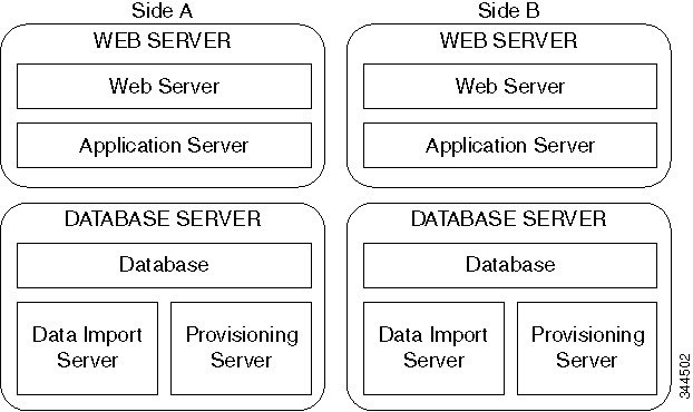
For Cisco HCS for Contact Center, implement a dual-tier (distributed) system as shown in the following figure. This involves separating the web and application components (App/Web Server) of the Unified CCDM from the database server components.
Deploy Unified CCDM Database Server
 Note | Before you install CCDM Database server, ensure that you have a naming convention ready for the CCDM Web server, as the host name of CCDM Web server is required during the installation and configuration of CCDM Database server. Do not use hyphens in the server name. Hyphens are not supported. |
Follow this sequence of tasks to install Unified CCDM database server on Side A and Side B.
After each task, return to this page to mark the task "done" and continue the sequence.
|
Sequence |
Done? |
Tasks |
Notes |
||
|---|---|---|---|---|---|
|
1 |
|
Download HCS-CC_11.0(1)_CCDM-CCE-CVP_vmv9_v1.0.ova |
|||
|
2 |
|
Create the virtual machine for the Unified CCDM Database Server |
|||
|
3 |
|
Install Microsoft Windows Server |
|||
|
4 |
|
Configure Windows |
|||
|
5 |
Associate Unified CCDM Component servers with Service Provider AD Domain |
Associate Unified CCDM Component servers with Service Provider AD Domain |
|||
|
6 |
|
Configure Secondary Drive |
|||
|
7 |
|
Install Microsoft SQL Server |
|||
|
8 |
|
Configure Post-Install |
|||
|
9 |
|
Install Service Pack 1 for the SQL server |
Run Service Pack 1 for SQL server |
||
|
10 |
|
Install Unified CCDM Database Server |
Install Unified CCDM Database Server on Side A and Side B
|
||
|
11 |
Install the Diagnostic Framework for System CLI |
Install the Diagnostic Framework for System CLI | |||
|
12 |
Install Unified CCDM portal Database |
Install Unified CCDM Portal Database on Side A and Side B | |||
|
13 |
Add SQL Login for Unified CCDM web server |
Add SQL Login for Unified CCDM Web Server | |||
|
14 |
Configuring SNMP Traps |
Configure SNMP Traps |
- Configure Windows
- Associate Unified CCDM Component servers with Service Provider AD Domain
- Configure Post-Install SQL
- Install Unified CCDM Database Server on Side A and Side B
- Install the Diagnostic Framework for System CLI
- Install Unified CCDM Portal Database on Side A and Side B
- Add SQL Login for Unified CCDM Web Server
Configure Windows
Configure Windows Feature Requirements
Turn Off FIPS Compliance
Complete the following procedure to turn off the FIPS compliance checking:
Disable UAC
User Account Control (UAC) protects the operating system from malicious programs. When enabled, UAC may cause issues with the software used to install the Unified CCDM. Disable UAC on all servers before you install the Unified CCDM. Complete the following procedure to disable UAC.
Associate Unified CCDM Component servers with Service Provider AD Domain
Complete the following procedure to associate the Unified CCDM Component servers with Service Provider AD Domain.
Configure Post-Install SQL
Complete the following procedures for post-install for SQL configuration:
Configure DTC
Complete the following procedure to configure Distributed Transaction Coordinator (DTC):
Configure Windows Server 2012 R2 Firewall for SQL Server
Complete the following procedure to configure Windows server 2012 R2 firewall for SQL server
SQL Server Backup Guidelines
Install Unified CCDM Database Server on Side A and Side B
For dual-tier systems, perform a complete installation on the Side A servers, and then perform a complete installation on the Side B servers.Make sure that the prerequisites are met before you perform these installations. For more information on the prerequisites, see Configure Windows Feature Requirements.
Complete the following procedure to install the Unified CCDM Database server:
Note | It is required to complete CCDM Web server Side A installation before installing the CCDM Database server on Side B. |
| Step 1 | Mount the correct version of the Unified CCDM ISO image to the virtual machine’s CD/DVD drive. For more information, see Mount and Unmount ISO Files. | ||
| Step 2 | Double-click the mounted ISO image. | ||
| Step 3 | In Cisco Unified CCDM Installation window, choose the component Database server under Server Installation and wait till it completes prerequisite checks, click Install. | ||
| Step 4 | In Domain Manager: Database Components - InstallShield wizard window, click Next. | ||
| Step 5 | Select I accept the terms in the license agreement in License Agreement window. Click Next. | ||
| Step 6 | Enter and
confirm the passphrase using 6 to 35 characters in the
Cryptography Configuration window, click
Next.
This passphrase is used for encrypting and decrypting system passwords and must be the same for all the servers in the cluster. The contents in the Confirm Passphrase must be identical to the passphrase entered above. | ||
| Step 7 | Configure the following in the Configure Database window and click Next: | ||
| Step 8 | In the Destination Folder window, accept the default location for the Database Server installation. Click Next. | ||
| Step 9 | In Ready to Install Program window, click Install. | ||
| Step 10 | After the installation, ensure Launch Database Management Utility check-box is unchecked. You can later set up the database manually. | ||
| Step 11 | Click
Finish.
|
Install the Diagnostic Framework for System CLI
Install Unified CCDM Portal Database on Side A and Side B
Complete the following procedure to setup the database server:
Add SQL Login for Unified CCDM Web Server
You must create SQL logins so that the Unified CCDM web server can connect to the database server in distributed deployment.
Complete the following procedure to configure Unified CCDM database for Side A and B:
Deploy Unified CCDM Web Server
Note | Do not use hyphens in the server name. Hyphens are not supported. |
Follow this sequence of tasks to install Unified CCDM Web server on Side A and Side B.
After each task, return to this page to mark the task "done" and continue the sequence.
|
Sequence |
Done? |
Tasks |
Notes |
||
|---|---|---|---|---|---|
|
1 |
Download HCS-CC_11.0(1)_CCDM-CCE-CVP_vmv9_v1.0.ova |
||||
|
2 |
Create the virtual machine for the Unified CCDM Web Server |
||||
|
3 |
Install Microsoft Windows Server |
||||
|
4 |
Configure Windows |
||||
|
5 |
Associate Unified CCDM Component servers with Service Provider AD Domain |
Associate Unified CCDM Component servers with Service Provider AD Domain |
|||
|
6 |
Configure Secondary Drive |
||||
|
7 |
Install Unified CCDM Web Server |
Install Unified CCDM Web Server on Side A and Side B
|
|||
|
8 |
Install the Diagnostic Framework for System CLI |
Install the Diagnostic Framework for System CLI | |||
|
9 |
Configuring SNMP Traps |
Configure SNMP Traps |
Install Unified CCDM Web Server on Side A and Side B
Note | It is required to complete CCDM Data server Side B installation before installing CCDM Web server on Side B. |
Complete the following procedure to install the App/Web server component:
| Step 1 | Mount the correct version of the Unified CCDM ISO image to the virtual machine’s CD/DVD drive. For more information, see Mount and Unmount ISO Files. | ||
| Step 2 | Double-click the mounted ISO image. | ||
| Step 3 | In Cisco Unified CCDM Installation window, choose App/Web Server and wait till it completes all prerequisite checks, click Install. | ||
| Step 4 | In Domain Manager: Application Server Components - IntsallShield Wizard window, click Next. | ||
| Step 5 | Select I accept the terms in the license agreement in License agreement window, and click Next. | ||
| Step 6 | Enter and
confirm the passphrase using 6 to 35 characters in
Cryptography Configuration window, and click
Next.
This passphrase is used for encrypting and decrypting system passwords and must be the same for all the servers in the cluster. The contents in the Confirm Passphrase must be identical to the passphrase entered above. | ||
| Step 7 | In Destination Folder window, accept the default location for the App/Web Server installation. Click Next. | ||
| Step 8 | Configure the
following in the
Configure Database window and click
Next:
| ||
| Step 9 | In Ready to Install the Program window click Install. When the installation completes, click Finish. | ||
| Step 10 | Click Yes to restart your system for the changes to take affect. |
Note | In a dual-sided Unified CCDM deployment setup, for replicating systems, repeat this installation for side B. It is required that you complete the side A installation of all components before installing side B. |
Configure SNMP Traps
Simple Network Management Protocol (SNMP) traps may be raised from Unified CCDM by configuring Windows to send selected events to an SNMP monitor. This is achieved using a Windows utility called evntwin.exe. This utility converts events written to the Windows Event log into SNMP traps that are raised and forwarded by the Windows SNMP service to an SNMP management tool.
To configure SNMP traps for use with Unified CCDM follow these steps:
Enable Windows SNMP Feature
To configure Windows event forwarding to SNMP, the SNMP feature in Windows must be enabled. To do this, on the Unified CCDM server containing the component for which traps are required:
Configure SNMP Service for Trap Forwarding
The SNMP Service must be configured to forward traps to the management tool that is being used for reporting and alerting.
Configure Windows Events to Forward to SNMP
Finally, use the evntwin.exe tool to configure the Windows events to be forwarded as SNMP traps. Any event that is raised in the Windows Event Log may be configured to generate an SNMP trap.
Unified CCDM Configuration
For the Unified CCDM to operate correctly, establish communications channels between the different Unified CCDM components so that each individual Unified CCDM component connects to the appropriate channels in the event of a failure.
Complete the procedures in the following order for Unified CCDM cluster configuration:
| Sequence | Done ? | Task | Notes |
|---|---|---|---|
|
1 |
|||
|
2 |
|||
|
3 |
|||
|
4 |
|||
|
5 |
- Launch the Integrated Configuration Environment
- Set Up Unified CCDM Servers
- Configure Replication
- Login to Unified CCDM
- Configure Single Sign-On
Launch the Integrated Configuration Environment
Complete the following procedure to launch the Integrated Configuration Environment (ICE) in Unified CCDM Dataserver.
| Step 1 | Open Integrated Configuration Environment application. |
| Step 2 | Enter the following details in the Database Connection page: |
| Step 3 | Click Test to test the connection to the Database Server for the first time. If the test fails, check the Database Connection settings. |
| Step 4 | Click
OK to open the ICE.
When ICE starts, the Cluster Configuration tool is loaded as the default tool. You can use the Tool drop-down in the toolbar to switch to other ICE tools. |
Set Up Unified CCDM Servers
Complete the following procedure to set up Unified CCDM servers.
| Step 1 | Launch Integrated Configuration Environment on Unified CCDM Database Server Side A, see Launch the Integrated Configuration Environment. |
| Step 2 | In Select Deployment Type, select the Two Tier option and click Next. |
| Step 3 | In Configure Redundancy select a Dual-Sided system and click Next. |
| Step 4 | For the two-tier deployment, enter the number of web servers for each side. For dual-sided configurations, you must configure an equal number of app/web servers on each side of the system and click Next. |
| Step 5 | In the Configure Servers page, configure the following: |
| Step 6 | Click Next. |
| Step 7 | In the Configure Application Servers (1) page, configure the following: |
| Step 8 | In the
Configure Database Connection page, enter the
following details:
|
| Step 9 | Click Next. |
| Step 10 | If you want to print the deployment summary, click Print below the summary list |
| Step 11 | Verify the
deployment details, and click
Next.
A confirmation message appears to indicate that the wizard has completed successfully. |
| Step 12 | Click Exit to close the wizard. |
| Step 13 | Click Save on ICE window. |
Configure Replication
In a dual-sided Unified CCDM deployment setup, use the SQL Server Replication to replicate Unified CCDM databases. Replication between these databases is set up and monitored using the Replication Manager application which is available in the Unified CCDM Integrated Configuration Environment (ICE).
Complete the procedures to configure replication in a dual-sided Unified CCDM deployment setup.
| Step 1 | Launch the Integrated Configuration Environment on Unified CCDM Database Server Side A. For more information, see Launch the Integrated Configuration Environment. |
| Step 2 | In the left pane, select Tool and select Replication Manager from the drop-down list. |
| Step 3 | Configure setup to enable SQL Server Replication for the Unified CCDM databases in a dual-sided environment. For more information, see Setup. |
| Step 4 | Configure monitor to check the general health of SQL Server Replication between Unified CCDM databases. For more information, see Monitor. |
Setup
The Setup option configures or disables SQL Server Replication for the Unified CCDM databases in a dual-sided environment.
| Step 1 | Select Setup tab to see the replication setup details and to configure or disable replication. | ||
| Step 2 | In the CCDM Database Server Properties, the Server Name and Catalog Name for each are defaulted to the values used when the Unified CCDM servers were configured with the ICE Cluster Configuration tool. | ||
| Step 3 | In Distributor Properties, by default, the Distributor is created on the Unified CCDM Database Subscriber Server. | ||
| Step 4 | Click
Configure to start the replication
configuration process.
|
Monitor
The Monitor option monitors the general health of SQL Server Replication between Unified CCDM databases. The Monitor can also start or stop various replication agents. The Monitor option shows the details only if SQL Server Replication is currently configured.
| Step 1 | Select Monitor tab. | ||
| Step 2 | After Unified CCDM is replicated, top-left pane shows the list of Publishers and Publications of each Publisher. | ||
| Step 3 | Select publications to see either Subscriptions or Agents details. Agents tab lists Snapshot Agent, Log Reader Agent and Queue Reader Agent, if available for the selected publication. | ||
| Step 4 | Select
subscriptions or agents to see their session details in the bottom left pane.
This pane lists all the agent sessions in the last 24 hours. Click each session to see the performed actions during the session. It also provides information about agents failure.
|
Login to Unified CCDM
| Step 1 | In the App/Web server, open Domain Manager application or enter https://<webserver FQDN>/Portal in browser. Displays Unified CCDM web page. |
| Step 2 | For login to a new system, use the username 'Administrator' and a blank password. You are prompted to change the administrator password. If you logged into an upgraded system, enter the password that you created when you first logged in. Re-enter the password to confirm. |
Configure Single Sign-On
By default, users must log in to Unified CCDM every time they connect. You can optionally configure Unified CCDM to use Single Sign-On (SSO), which allows users to connect to Unified CCDM without logging in by linking their Unified CCDM user accounts with their Active Directory user accounts.
Note | Users cannot use SSO over a proxy connection. Setting up SSO disables any existing Unified CCDM users that are not in domain login format. You must set up new Unified CCDM user accounts for all existing users. |
Setup Administrator Account
It is important to set up the new SSO administrator account correctly, because the Unified CCDM administrator account is disabled when SSO is configured. Complete the following procedure to administrator account setup.
Create users in active directory, see Create Users in Active Directory.
| Step 1 | In the CCDM Web Server, open the Domain Manager. Log in to Unified CCDM as Administrator. | ||
| Step 2 | In
Security >
Users, create a user account to be the new
administrator account.
| ||
| Step 3 | Enter the password, re-enter and confirm the password. | ||
| Step 4 | Check the Advanced mode check box. | ||
| Step 5 | Click Save. | ||
| Step 6 | Click on the newly created user and choose Groups tab. | ||
| Step 7 | Click Add to Group. | ||
| Step 8 | Check the Administrators group check box and click Ok. | ||
| Step 9 | Click Save. |
Configure SSO Authentication for Unified CCDM
Complete the following procedure to configure SSO authentication for Unified CCDM.
| Step 1 | Launch Integrated Configuration Environment on CCDM Database Server Side A, see Launch the Integrated Configuration Environment. | ||
| Step 2 | Select System Properties in the Tools drop-down list in the Integrated Configuration Environment. | ||
| Step 3 | In the Global properties tab, navigate to . | ||
| Step 4 | Using the drop-down against the property value, change the value from Portal to Active Directory. | ||
| Step 5 | Save the configuration changes, and click Exit. | ||
| Step 6 | On the Application and Web server, navigate to the location where Unified CCDM is installed (usually C:\Program Files\Domain manager ). Right-click the Web folder and click Properties. | ||
| Step 7 | Select the Security tab and ensure that all the domain users have both Read, Read and Execute permissions on this folder. | ||
| Step 8 | Click Advanced settings. Ensure that Replace all child object-permission entries with inheritable permission entries from this object is selected. If not, click Change Permissions, select the option and click OK. | ||
| Step 9 | Click OK to close the properties dialog. | ||
| Step 10 | Run
iisreset command, from a command window for all CCDM
servers.
|
Manage Users with Single Sign-On
After you set up, assign all the Unified CCDM users with a Unified CCDM login in the format <DOMAIN>\<Windows domain login>. This implies that you must re-create the previously existing Unified CCDM user accounts in the new format before any users can log in.
Each time you give a new user a Unified CCDM account, you must give Read/Read & Execute properties on the Web directory, or you must add that user to a user group that has those permissions.
The first time a user access Unified CCDM using SSO, a dialog box may appear requesting for Windows username and password. To sign in automatically, the user will have to add the Unified CCDM website to the list of local intranet sites in their browser.
Administrator can create Users for the tenant that is created. See, Configure User.
Obtaining Digital Certificate
Perform the following procedures to obtain the digital certificate.
- Install Active Directory Certificate on Domain Controller Box
- Install Active Directory Certificate on CCDM Web Server and Data Server
- Install Active Directory Certificate on CCDM Web Server.
Install Active Directory Certificate on Domain Controller Box
Select Start > Administrative Tools > Server Manager > Roles and expand, if the Active Directory Certificate services are present, see Installing the Security Certificate in the User Certificate Store
If the Active Directory Certificate is not present then perform the following steps to install the Active Directory Certificate Services.
| Step 1 | Select Server Manager > Roles > Summary and click Add Roles and click Next. | ||
| Step 2 | Check Active Directory Certificate Services check-box on Select Service Roles page and click Next. | ||
| Step 3 | Check Certification Authority check-box and click Next. | ||
| Step 4 | Select Enterprise Type in Specify Set Up type page and click Next. | ||
| Step 5 | Select
Create New
Private Key in Set Up Private Key page and click
Next until
the installation begins
| ||
| Step 6 | Click Close. | ||
| Step 7 | In the command prompt, type mmc in the command box to open Microsoft Management Console (MMC). | ||
| Step 8 | Click File > Add/Remove Snap-in > Certificates > Add . | ||
| Step 9 | In the Certificates Snap-in dialogue box, select Computer Account and click Next. | ||
| Step 10 | In the Select Computer dialogue box, select Local Computer option and click Finish and click OK. | ||
| Step 11 | Expand the Certificates node and Trusted Root Certificate node, click Certificates to see the available certificates. Right-click on the certificate that you created through Creating the Active Directory Certificate Services. | ||
| Step 12 | Right-Click on selected Certificate and click All Tasks and click Export . | ||
| Step 13 | Accept the default format and click Next. | ||
| Step 14 | Specify a file name and click Next and click Finish. | ||
| Step 15 | Copy the Certificate that you have exported into CCDM web Servers and Data Servers box. |
Install Active Directory Certificate on CCDM Web Server and Data Server
| Step 1 | In command prompt type mmc and open the MMC. |
| Step 2 | Click File > Add/Remove Snap-in > Certificates > Add. |
| Step 3 | Select Computer Account and click Next. |
| Step 4 | Select Local computer and click Finish and click OK. Certificates snap-in will be added to MMC |
| Step 5 | Expand the Certificates (Local Computer) node Trusted Root Certificate Authorities node, right-click Certificates and select All Tasks > Import. |
| Step 6 | In the Certificate Import Wizard, click Next. |
| Step 7 | Browse to the certificate file you copied from Domain Controller and click Open and then click Next . |
| Step 8 | Select Place all certificates in the following store and then browse and locate the Trusted, click Next and click Finish |
| Step 9 | Reboot the server. |
Install Active Directory Certificate on CCDM Web Server.
| Step 1 | Open Internet Information Services (IIS) Manager and select the web server in the folder hierarchy. |
| Step 2 | Select the Features View tab, click Server Certificates. |
| Step 3 | Create a
digital certificate in one of the following ways:
|
What to Do Next
Configure SSL for Unified CCDM
After you have a suitable digital certificate, configure SSL for Unified CCDM. On the App/Web Server
| Step 1 | Open Internet Information Services (IIS) Manager , expand the folder tree below the web server and select the web site that the Unified CCDM web application resides on. |
| Step 2 | In the Actions pane, select to display the Site Bindings dialog box. |
| Step 3 | If there is no existing binding for https, click Add to display the Add Site Binding dialog box. |
| Step 4 | If there is an existing binding for https, select it and click Edit to display the Edit Site Binding dialog box, edit the settings to the values in step 3. above and click OK . |
| Step 5 | In the folder tree, select the Portal Application. |
| Step 6 | Select the Features View tab, and click on SSL Settings in the IIS group. |
| Step 7 | Select the Require SSL, and retain the default Ignore for Client Settings |
| Step 8 | In the Actions pane, click Apply to apply these settings. |
| Step 9 | Close IIS Manager. |
Grant Network Service Rights to the Certificate
Grant Network Service Rights to the Certificate to grant network service rights to the certificate, on the App/Web Server:
| Step 1 | In the Start menu, type mmc in the command box to open Microsoft Management Console (MMC). |
| Step 2 | Click , then Add . |
| Step 3 | In the Certificates Snap-in dialog box, select Computer Account and click Next . |
| Step 4 | In the Select Computer dialog box, select Local Computer and click Finish to add the Certificates snap-in to MMC. Click OK . |
| Step 5 | In MMC, expand the Certificates node and the Personal node, then click Certificates to see the available certificates. |
| Step 6 | Right-click on the certificate you want to use, select . |
| Step 7 | In the Permissions for Private Keys dialog box, click Add. |
| Step 8 | In the Select Users, Computers, Service or Groups dialog box, type NETWORK SERVICE , then click Check Names. The name will be underlined if it has been entered correctly. Click OK . |
| Step 9 | In the Permissions for Private Keys dialog box, select the NETWORK SERVICE user, then in the Full Control row, select the check box in the Allow column. Click OK . |
Obtain the Certificate Thumbprint
To obtain the certificate thumbprint, on the App/Web Server:
| Step 1 | In MMC, expand the Certificates node and the Personal node to see the available certificates and select the certificate you want to use. |
| Step 2 | Double-click on the Certificate. |
| Step 3 | In the Certificate dialog box, select the Details tab, and click
Thumbprint.
The thumbprint for this certificate is displayed on the lower part of the screen as a text string. |
| Step 4 | Select the thumbprint text string, copy it and paste it into a
text editor. Edit the string to remove all the spaces. For example, if the
thumbprint text string you copied was: c3 34 9a 43 28 d3 a7 75 a9 93 eb 31 5c
bf e0 62 51 6d b8 18 you need to edit it to become:
c3349a4328d3a775a993eb315cbfe062516db818
Save this thumbprint value as you will need it several times in the next step. |
Configure Web Services to Use the Certificate
To configure Web Services to use the certificate, on the App/Web Server:
| Step 1 | Use Windows Services or the Service Manager in the ICE tool (see the Administration Guide for Cisco Unified Contact Center Domain Manager ) to stop all Unified CCDM services. | ||
| Step 2 | Enter the following commands to remove the existing localhost certificates for each Web Services: | ||
| Step 3 | Enter the
following commands to add the new certificates for each Web Services:
Example:Consider thumbprint value from the section 6.2.5 and obtain the certificate thumbprint to update subscription manager certificate, enter the following command: netsh http add sslcert ipport=0.0.0.0:8083 certhash=c3349a4328d3a775a993eb315cbfe062516db818 appid={ 16dde36c-787e-4dc7-bdc0-fd4ae0eb189a}
|
Test the Certificate Installation
To test the certificate installation, in Internet Explorer, navigate to each of the locations below, where <Server> is the name of the App/Web Server.
https://<Server>:8083/SubscriptionManager?wsdl
https://<Server>:8085/ResourceManagement?wsdl
https://<Server>:8086/HierarchyManagement?wsdl
https://<Server>:8087/AnalyticData?wsdl
| Step 1 | Enter mmc in the command box to open MMC. |
| Step 2 | Click . |
| Step 3 | In the Certificates Snap-in dialogue box, select Computer account and click Next. |
| Step 4 | In the Select Computer dialogue box, select Local computer and click Finish to add the Certificates snap-in to MMC. Click OK. |
| Step 5 | In MMC, expand the Certificates (Local Computer) node Trusted Root Certificate Authorities node, then right-click Certificates and select . |
| Step 6 | In the Certificate Import Wizard, click Next. |
| Step 7 | In the File to Import dialogue box, browse to the certificate file you copied from DC and click Open and then click Next. |
| Step 8 | In the Certificate Store dialogue box, select the option, Place all certificates in the following store, then Browse and locate the Trusted Root Certificate Authorities store and click OK. |
| Step 9 | In the Certificate Store dialogue box, click Next. Review the settings and click Finish. Repeat the steps given in section Test the Certificate Installation. |
Installing the Security Certificate in the User Certificate Store
To install the Unified CCE ConfigWebService security certificate in the user certificate store, you need to locate the certificate and import it into your certificate store on each Unified CCDM database server.
| Step 1 | Choose to start ICE. |
| Step 2 | Enter the credentials for your database. Click OK if there is any warning or error message displayed. |
| Step 3 | In the ICE Cluster Configuration tool, select the Resources tab and navigate to the Unified CCE instance. Select the Components tab. From this you can determine the URL of the Unified CCE ConfigWebService. |
| Step 4 | In Internet Explorer, navigate to the URL you found above. If the certificate has not been installed on this server, you will see a certificate error. |
| Step 5 | Click Certificate Error in the top right hand corner of the window. |
| Step 6 | In the Untrusted Certificate dialog box, select View Certificates. |
| Step 7 | In the Certificate dialog, note the "Issued to:" name (you will need this name to locate the certificate again below) and click Install Certificate. |
| Step 8 | In the Certificate Import Wizard, click Next. |
| Step 9 | In the Certificate Store dialog box, select Place all certificates in the following store, and click Browse. Choose Trusted Root Certificate Authorities and click OK to return to the Certificate Store dialog box. |
| Step 10 | In the Certificate Store dialog box, click Next. Review the settings and click Finish. |
| Step 11 | Click OK if there is any warning or error message displayed. When the import completes, click OK. |
Installing the Security Certificate in the Computer Certificate Store
- To Export the Certificate, on each CCDM database server
- To Import the Certificate, on each CCDM database server
To Export the Certificate, on each CCDM database server
| Step 1 | Enter mmc in the command box to open Microsoft Management Console (MMC). |
| Step 2 | Click File > Add/Remove Snap-in>Certificates> Add. |
| Step 3 | In the Certificates Snap-in dialog box, select My user account and click Finish and Click OK. |
| Step 4 | In MMC, expand the Certificates - Current User node, Trusted Root Certificate Authorities node, then click Certificates to see the available certificates. |
| Step 5 | Locate the certificate you imported in the section above, right-click on it, and select All Tasks > Export . |
| Step 6 | In the Certificate Export Wizard, select Next. |
| Step 7 | In the Export File Format dialog box, accept the default format and click Next. |
| Step 8 | In the File to Export dialog box, specify a file name and click Next. Review the settings and click Finish. |
To Import the Certificate, on each CCDM database server
| Step 1 | Enter mmc in the command box to open MMC. |
| Step 2 | Click File > Add/Remove Snap-in > Certificates>Add. |
| Step 3 | In the Certificates Snap-in dialog box, select Computer account and click Next. |
| Step 4 | In the Select Computer dialog box, select Local computer and click Finish to add the Certificates snap-in to MMC. Click OK. |
| Step 5 | In MMC, expand the Certificates (Local Computer) node Trusted Root Certificate Authorities node, then right-click Certificates and select All Tasks > Import. |
| Step 6 | In the Certificate Import Wizard, click Next. |
| Step 7 | In the File to Import dialog box, browse to the certificate file you exported and click Open and then click Next. |
| Step 8 | In the Certificate Store dialog box, select the option, Place all certificates in the following store, then Browse and locate the Trusted Root Certificate Authorities store and click OK. |
| Step 9 | In the Certificate Store dialog box, click Next. Review the settings and click Finish. |
Install and Configure Unified Communication Domain Manager
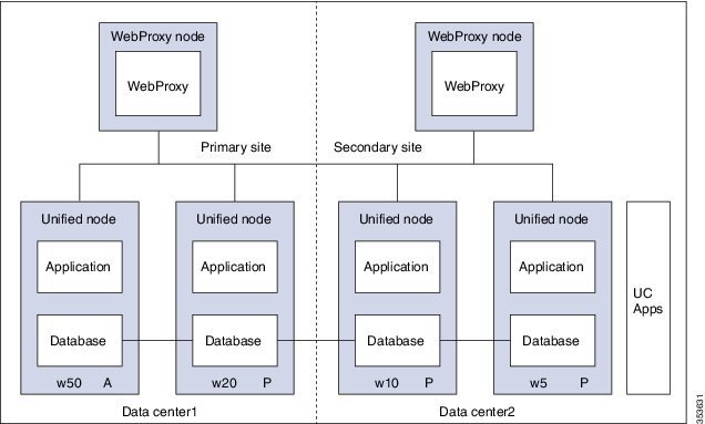
- A WebProxy role installs only the front-end web sever together with ability to distribute load among multiple middleware nodes
- A Unified node comprises Application and Database roles on a single node
- WebProxy and Unified nodes can be contained in separate firewalled networks
- Database synchronization takes places between all Database roles, thereby offering Disaster Recovery and High Availability
- All nodes in the cluster are active
- Install Unified Communication Domain Manager
- Post Installation
- Install Hosted Collaboration Mediation-Fulfilment
- Prerequisites to Configure Unified Communication Domain Manager
Install Unified Communication Domain Manager
| Step 1 | After obtaining the OVA file from Cisco.com, deploy the OVF template from the vSphere Client. The setup file contains the OVA file along with software and platform upgrade files. |
| Step 2 | Power on the virtual machine (VM). The Setup wizard starts to configure the system. |
| Step 3 | Choose each options and provide the necessary details: |
| Step 4 | Choose install. |
Post Installation
| Step 1 | Login to each
node and update security.
Example: platform@cucdm-tb3-un-01:~$ security check There are 181 security updates available Please install them with: security update platform@cucdm-tb3-un-01:~$ security update
| ||||||
| Step 2 | To open ports
for Cluster Communication:
| ||||||
| Step 3 | Add nodes to Cluster. Perform the following on one of the node: | ||||||
| Step 4 | Add Network
Domain:
| ||||||
| Step 5 | Provision
cluster:
| ||||||
| Step 6 | Enter voss cleardown command to initialize and clear the cache. | ||||||
| Step 7 | Import
template:
|
Install Hosted Collaboration Mediation-Fulfilment
The Fulfillment service responds to data changes in the Shared Data Repository related to the Cisco Unified Communication Manager.
The Cisco HCM-F administrative interface is the user interface to the Cisco HCM-F services. It allows you to perform management and configuration tasks on the Cisco HCM-F services.
| Step 1 | After obtaining the OVA file from Cisco.com, deploy the OVF template from the vSphere Client. The setup file contains the OVA file along with software and platform upgrade files. | ||
| Step 2 | Choose HCM-F APP from Configuration drop-down list. | ||
| Step 3 | Power on the virtual machine (VM) and open the console. The Setup wizard starts to configure the system. | ||
| Step 4 | On Media Check screen, click OK to perform a check of the media, or click Skip to proceed to the installation. | ||
| Step 5 | On Product Deployment Selection screen, choose HCS Application Suite and then click OK. | ||
| Step 6 | On Proceed with Install screen, verify that you are installing the version you want, and click Yes to overwrite the hard drive. | ||
| Step 7 | On Platform Installation Wizard screen, choose Proceed. | ||
| Step 8 | On Basic Install screen, click Continue. | ||
| Step 9 | On Timezone Configuration screen, choose your time zone from the list, and then click OK. | ||
| Step 10 | On Auto Negotiation Configuration screen, click Continue. | ||
| Step 11 | On MTU Configuration screen, click No to leave the MTU size at the OS default, or click Yes and enter new values. | ||
| Step 12 | On
DHCP
Configuration screen, click
No to use a static IP address. On
Static
Network Configuration page, enter
Host
Name,
IP
Address,
IP
Mask,
GW
Address and click
Ok.
| ||
| Step 13 | On
DNS
Client Configuration screen:
| ||
| Step 14 | On Administrator Login Configuration screen, set up Administrator ID and Password for the AppNode. Then click OK. | ||
| Step 15 | On Certificate Information screen, enter values for Organization, Unit, Location, and State. Choose Country from the menu. Then click OK. | ||
| Step 16 | On Network Time Protocol Client Configuration screen, enter hostname or IP address for one to five NTP Servers. Then click OK. | ||
| Step 17 | On Security Configuration screen set the system security password for the App Node. Then click OK. | ||
| Step 18 | On Platform Configuration Confirmation screen, click OK. After installation, it displays login console. |
Prerequisites to Configure Unified Communication Domain Manager
Add HCM-F Device
Add Provider
Add Reseller
| Step 1 | Login to the Cisco Unified Communications Domain Manager as the Provider admin. Enter provider admin’s email address as username, it is case sensitive. Example:<provider_name>Admin@<domain_name>. |
| Step 2 | Navigate to from the menu. |
| Step 3 | Click Add. |
| Step 4 | Provide necessary details in the following: |
| Step 5 | Click Save. |
What to Do Next
To integrate Unified Communication Domain Manager with the customer instance, see Cisco UCDM Integration.
Install and Configure ASA Firewall and NAT
Cisco Adaptive Security Appliance (ASA) Firewall partitions a single ASA into multiple virtual devices that keeps customer traffic separate and secure, and also makes configuration easier. All customer traffic is first sent to the firewall before forwarding to the computer resources.
Setup ASA
Complete the following procedure to initiate the basic setup in Cisco ASA.
Access Command-line Interface
Configure Hostname and Password
| Step 1 | Enter the
following commands to access privileged EXEC mode:
hostname>enable
Password:
hostname#
| ||
| Step 2 | Enter the
following commands to access the global configuration mode:
hostname#configure terminal hostname(config)# | ||
| Step 3 | Enter
hostname command to configure the hostname:
Example: hostname(config)#hostname CISCOASA CISCOASA(config)# | ||
| Step 4 | Enter
enable
passsword command to configure the password:
CISCOASA(config)#enable password <enter the password> Example: CISCOASA(config)#enable password Password1234 CISCOASA(config)#exit | ||
| Step 5 | Enter the
following commands to save configuration:
hostname# copy running-config startup-config |
Configure Multiple Context Modes
Complete the following procedures to configure multiple context modes on ASA Firewall:
Enable Multiple Context Modes
hostname#changeto system
hostname#configure terminal
hostname(config)#mode multiple
|
Enable Interfaces in the System Execution Space
Complete the following procedure to configure interfaces in the system execution space:
| Step 1 | Navigate to
interface management 0/0 and enter the following commands:
hostname(config)#interface management 0/0 hostname(config-if)#no shut |
| Step 2 | Navigate to interface gigabitethernet 0/0 and enter the following
commands:
hostname(config)#interface gigabitethernet 0/0 hostname(config-if)#no shut |
Configure Security Contexts in System Execution Space
Complete the following procedure to configure security contexts:
Assign MAC Addresses to Context Interfaces Automatically (Optional)
Complete the following procedure to automatically assign MAC addresses to context interfaces:
hostname(config)#mac-address auto |
Configure Interfaces in the Context
Complete the following procedure to configure interfaces in the admin context:
| Step 1 | Navigate to
admin context in configure mode:
hostname#changeto context admin |
| Step 2 | Navigate to
the interface management:
hostname/admin#configure terminal hostname/admin(config)#interface management 0/0 |
| Step 3 | Enter a name
for management interface of the admin context:
hostname/admin(config-if)#nameif managementEnter the IP address of the management interface: hostname/admin(config-if)#ip address ip_address subnet_mask hostname/admin(config-if)#exit Example: hostname/admin(config-if)#ip address 209.165.200.225 255.255.255.224 |
| Step 4 | Configure the
following in global configuration mode to allow SSH to the admin context:
|
What to Do Next
To integrate Cisco ASA with the customer instance, see ASA Integration.
Install and Configure Perimeta SBC
This section describes the steps to deploy Perimeta SBC for HCS deployment model. For HCS, it is validated on C-Series platform.
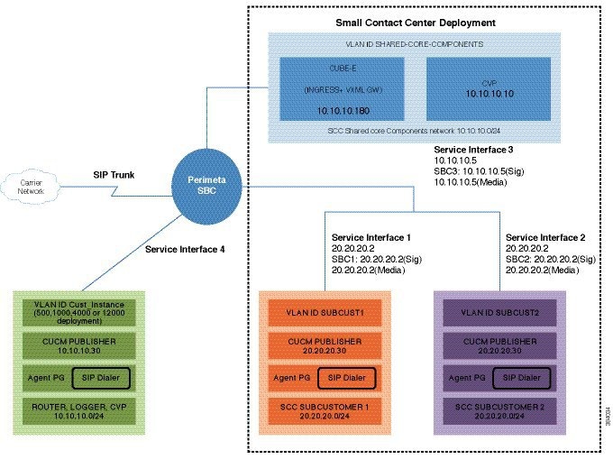
Perimeta SBC performs address translation and the media anchor role for inter-enterprise and off net Calls. Each sub customer CUCMs forward inter-enterprise and off-net calls to Perimeta SBC over SIP trunks, which in turn forward the calls to Carrier-Network. Perimeta SBC also receives calls from Carrier-Network and forwards the calls to each sub customer CUCM's. Routing decisions inside Perimeta SBC are based on source adjacency (to the SIP trunk from which the call was received), so Perimeta SBC maintains adjacency relationships to all sub customer components (CUCM, MediaSense), shared core components (CUBE (E), CVP Server's) and Carrier-Network. Perimeta SBC is manually provisioned using IOS CLI.
- Hardware Specification
- CIMC Setup
- Advanced BIOS Configuration
- Install Perimeta SBC
- Configure Perimeta SBC
Hardware Specification
This section provides an information on how to get the Cisco C240 M3 platform ready to install with Perimeta. It covers the Perimeta-specific cabling and the BIOS settings required by Perimeta.
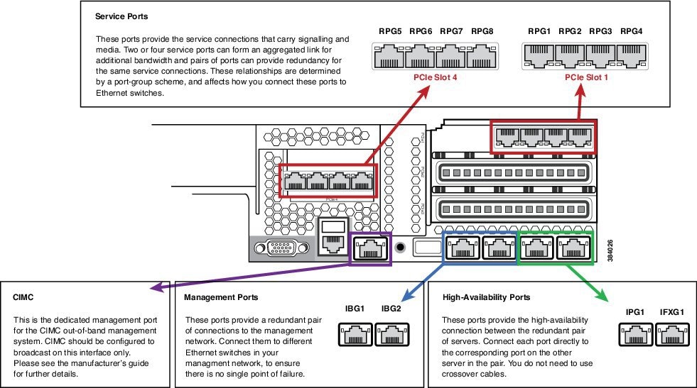
Cisco C240 M3 Network interfaces should have a total of 13 NICs. This includes:
-
Four embedded 1Gb Ethernet ports
-
CIMC out-of-band hardware management port
-
Eight 1 Gb Ethernet ports, made available from two PCIe cards
The below figure shows the locations of the network interfaces on a Cisco C240 M3 blade, and how Perimeta labels and uses them.
CIMC Setup
Use a VGA monitor and a USB keyboard to get direct console access, and use this to configure CIMC. On system boot select CIMC configuration (press F8 at the relevantprompt).
Configure CIMC with a dedicated IP address and subnet configuration, and with a user/password. It also should be configured to be accessible through only the dedicated management port. For more information, see the Cisco CIMC documentation.
Advanced BIOS Configuration
Set the advanced BIOS configuration to match that specified in table below. This is required to ensure that the Perimeta system performs at full capacity at all times.
Advanced BIOS configuration can be set in the CIMC over HTTPS.
|
Field |
Value |
|---|---|
| ASPM Support | Disabled |
| Intel(R) VT-d ATS Support | Enabled |
| Adjacent Cache Line Prefetcher | Enabled |
| NUMA | Enabled |
| Power Technology | Energy Efficient |
| Channel Interleaving | Auto |
| Intel(R) VT-d Coherency Support | Disabled |
| Number of Enabled Cores | All |
| Energy Performance | Performance |
| Frequency Floor Override | Enabled |
| CPU Performance | HPC |
| DRAM Clock Throttling | Performance |
| DCU IP Prefetch | Enabled |
| DCU Streamer Prefetch | Enabled |
| Demand Scrub | Enabled |
| Direct Cache Access Support | Enabled |
| Onboard SCU Storage Support | Disabled |
| DRAM Refresh Rate | 2x |
| Enhanced Intel Speedstep(R) Tec | Enabled |
Install Perimeta SBC
This section provides a brief overview and describes the minimal steps to deploy Perimeta SBC for HCS deployment models.
| Sequence | Task | Done |
|---|---|---|
| 1 | Mount Perimeta ISO | |
| 2 | Configure the Management Network | |
| 3 | Configure DNS Servers | |
| 4 | Unpack the Software | |
| 5 | Configure System, Node, and Remote Node Names | |
| 6 | Managing Local Timezone, Time and Date, and NTP Server | |
| 7 | Commissioning and Partnering the System | |
| 8 | Apply Licenses |
Mount Perimeta ISO
| Step 1 | Log in to Cisco Integrated Management Controller. |
| Step 2 | Click Power on to turn on the server. |
| Step 3 | Select . |
| Step 4 | Select Accept this Session option and click Apply. |
| Step 5 | Select . |
| Step 6 | Click Browse and select the ISO location. |
| Step 7 | Click Map Device. |
| Step 8 | Press Enter to boot from the mapped ISO. Installation begins. |
| Step 9 | After the installation, restart the server. |
Configure the Management Network
| Step 1 | Login to Craft Console using the default username and password.
The default username is defcraft and password is !defcraft. |
| Step 2 | Choose . |
| Step 3 | Enter the Management IP address and Subnet mask, Press Enter. |
| Step 4 | Enter the Processor A management IP address, Processor A probing IP address for management port 1, Processor A probing IP address for management port 2. |
| Step 5 | If your Session Controller has two processors, enter the Processor B management IP address, Processor B probing IP address for management port 1, Processor B probing IP address for management port 2. |
| Step 6 | Enter the management network default gateway IP address, then press Enter. |
| Step 7 | The following are optional configurations, if you have chosen not to configure a value for this address then press Enter. |
| Step 8 | The Craft terminal shows a summary of your selections, choose OK. |
Configure DNS Servers
Unpack the Software
Install Software
Configure System, Node, and Remote Node Names
Managing Local Timezone, Time and Date, and NTP Server
Commissioning and Partnering the System
Apply Licenses
Both physical USB token and license key are required for license activation.
Configure Perimeta SBC
Following figure shows Perimeta SBC topology for HCS deployment models.
Configuration of C-Series Perimeta SBC for all HCS Deployment models
This section includes all the configurations for all HCS deployment models in Perimeta SBC.
- Configure Service Interface for Carrier Network
- Configure Codec List
- Configure Media Address
- Create Account
Configure Service Interface for Carrier Network
To create the service interface for carrier network perform the following instructions. This is used for vPGW and for other applications which are in HCS aggregation layer.
config
	system
		service-interface serv5
			description CarrierNetwork
			service-network 5
				port-group-name CoreNetwork
			ipv4
					subnet-prefix-length 24
					gateway-ip-address 192.168.10.1
					local-ip-address 192.168.10.2
						service-address Extra
					probes-source-style specific-source
					activate
				vlan-id 5
				network-security trusted
Configure Codec List
To configure codec list, perform the following instructions.
sbc
    codec list codec-list-1
      description codeclist
      codec-entry G729 3
      codec-entry PCMA 2
      codec-entry PCMU 1
      codec-entry telephone-event 9
Configure Media Address
For each network, mention the IP address to be used for media. Media IP addresses is required for Carrier Network - 5:
Note | Same IP address is used for both signaling and media, as HCS deployment model use Integrated Session Controller (ISC). |
Enter the following commands to add media address:
sbc
    media
      media-address ipv4 192.168.10.2 service-network 5
        port-range 16384 65535
To define media address for newly added sub-customers see, Configure Media Address for Sub-customer
Create Account
Enter the following commands to create an account:
config
	sbc
		signaling
      account carrier 5
To integrate Perimeta SBC with customer instance see, Perimeta SBC Integration.
Install and Configure Prime Collaboration Assurance
Software Download Link:
Prime Collaboration Assurance Software download
- For small, medium, and large deployment models requires only one virtual machine to install and configure Prime Collaboration Assurance. To learn about configuring these deployment models, see Simple Deployment section in the prime document
- For very large deployment models: You must configure Prime Collaboration Assurance OVA for database and application on separate virtual machines. To learn about configuring these deployment models, see Advance Deployment section in the prime document
During the installation of Prime Collaboration Assurance, if there are multiple networks in UCS, ensure that the virtual machine network you select belongs to Prime Collaboration is reachable.
For information on Requirements for Prime Collaboration Assurance (includes Analytics) refer the link Prime Collaboration Assurance
- Deploying Prime Collaboration Assurance
- Configuring the Prime Collaboration Assurance Virtual Appliance
- SSL Certificate Installation
Deploying Prime Collaboration Assurance
Based on the OVA you downloaded, you can deploy Prime Collaboration Assurance as follows:
Ensure that the requirements listed in Installation Requirements and System Requirements have been met as per the Prime document.
Simple Prime Collaboration Assurance Deployment
You can deploy Prime Collaboration Assurance OVA for small, medium, and large deployment models:
| Step 1 | Launch your VMWare vSphere client and choose File > Deploy OVF Template. |
| Step 2 | Click Browse and navigate to the location where you saved the Prime Collaboration Assurance OVA file. Click Next. |
| Step 3 | In the OVF Template Details window, verify the details about the OVA file, including the product name, version, and size, then click Next. |
| Step 4 | Click Accept to accept the end-user license agreement. Click Next. |
| Step 5 | In the Name window, specify a name for the template that you are deploying. The name must be unique within the inventory folder and can contain up to 80 characters. In the Inventory Location window, select the folder where you want to deploy the file, and click Next. |
| Step 6 | In the Disk Format window, select Thick provisioned format to store on the virtual disks, then click Next. |
| Step 7 | Verify the options in the Ready to Complete window, then click Finish to start the deployment. The deployment takes about 30 minutes to complete. Check the progress bar in the Deploying Virtual Appliance window to monitor the task status. |
| Step 8 | After the deployment task is complete, click Close in the confirmation message box. The virtual appliance that you deployed appears in the left pane of the vSphere client, under the host. As a part of the next process, follow Configuring the Prime Collaboration Assurance Virtual Appliance. |
Advanced Prime Collaboration Assurance Deployment
Following is the procedure to deploy Prime Collaboration Assurance very large OVA deployment model.
| Step 1 | Launch your VMWare vSphere client and choose File > Deploy OVF Template. |
| Step 2 | Click Browse and navigate to the location where you saved the Prime Collaboration Assurance OVA file. Click Next |
| Step 3 | In the OVF Template Details window, verify the details about the OVA file, including the product name, version, and size, and then click Next. |
| Step 4 | Click Accept to accept the end-user license agreement. Click Next. |
| Step 5 | In the Name window, specify a name for the template. The name must be unique within the inventory folder and can contain up to 80 characters. In the Inventory Location window, select the folder where you want to deploy the file and click Next. |
| Step 6 | If you choose
to enable
Prime
Collaboration Analytics in very large OVA deployment of
Prime
Collaboration Assurance, you require two virtual machines -
database
and
application. Recommended, install the
database
server first so that you can have the database server IP address, this is
required while installing application server. Configure the database server
before to application server. To configure the database server.
|
Configuring the Prime Collaboration Assurance Virtual Appliance
After you deploy the Prime Collaboration Assurance OVA, you must configure the virtual appliance.
Based on the OVA you have downloaded, you can configure the Prime Collaboration Assurance virtual appliance as follows:
- Simple Prime Collaboration Assurance Configuration
- Advanced Prime Collaboration Assurance Configuration
Simple Prime Collaboration Assurance Configuration
You can configure Prime Collaboration Assurance OVA for small, medium, and large deployment models:
| Step 1 | Right-click the virtual appliance and choose Power > Power ON to start the virtual machine. | ||
| Step 2 | In the virtual appliance console, enter setup at the localhost login prompt. | ||
| Step 3 | Enter the
required parameters at the console prompts. Press Enter to bring up the next
parameter. For the Installation Mode prompt, enter
1 to
select
Standard Prime
Collaboration Assurance, or
2 to
select
Advanced Prime
Collaboration Assurance Evaluation. The Default value is
1.
The virtual machine will reboot.
| ||
| Step 4 | If you have
selected the
Advanced Prime
Collaboration Assurance Evaluation option, select the
Managed
Service Provider (MSP) mode of deployment. Enter
M to
deploy Prime Collaboration Assurance in the MSP mode.
Each mode provides a different customer view option. For more information, see
Overview of Cisco Prime Collaboration - Assurance section in the
Cisco Prime Collaboration
Assurance Guide - Advanced, 10.5.
| ||
| Step 5 | After installation (when you see the login prompt in the console), wait for approximately 20 minutes for the Prime Collaboration Assurance processes to be listed on the console, and then log in to the Prime Collaboration Assurance UI. | ||
| Step 6 | Log in to the Prime Collaboration Assurance server to verify the installation. See the How to verify the Cisco Prime Collaboration Assurance Standard installation and How to verify the Cisco Prime Collaboration Assurance Advanced installation sections in Troubleshooting Cisco Prime Collaboration. |
Advanced Prime Collaboration Assurance Configuration
You can configure Prime Collaboration Assurance OVA for very large deployment model.
| Step 1 | Right-click virtual appliance and choose Power > Power ON to start the virtual machine. | ||
| Step 2 | In the virtual appliance console, enter setup at the localhost login prompt. | ||
| Step 3 | Enter the
required parameters at the console prompts.
| ||
| Step 4 | After
entering each parameter, press Enter to bring up the next parameter. For the
Installation Mode prompt, enter
1 to
select
Standard Prime
Collaboration Assurance, or
2 to
select
Advanced Prime
Collaboration Assurance Evaluation. The default value is
1.
| ||
| Step 5 | If you have
selected the
Advanced Prime
Collaboration Assurance Evaluation option, select the the
Managed
Service Provider (MSP) mode of deployment. Enter
M to
deploy Prime Collaboration Assurance in the MSP mode.
Each mode provides a different customer
view
option. For more information, see section "Overview of Cisco Prime
Collaboration - Assurance" in the
Cisco Prime Collaboration
Assurance Guide - Advanced, 10.5
.
| ||
| Step 6 | If you have
downloaded the very large OVA deployment model, you are prompted to enter the
type of server to be configured.
| ||
| Step 7 | After the installation (when you see the login prompt in the console), wait for approximately 20 minutes for the Prime Collaboration Assurance processes to be listed on the console, and then log in to the Prime Collaboration Assurance UI. | ||
| Step 8 | Log in to the Prime Collaboration Assurance server to verify the installation. See the "How to verify the Cisco Prime Collaboration Assurance Standard installation" and "How to verify the Cisco Prime Collaboration Assurance Advanced installation" sections in Troubleshooting Cisco Prime Collaboration. |
SSL Certificate Installation
- Windows Internet Explorer: You can permanently remove the SSL certificate warning by installing the Prime Collaboration self-signed certificate. See, Removing SSL Certificate Warning from Windows Internet Explorer
- Mozilla Firefox: You can remove the SSL certificate warning only by adding an exception. See, Removing SSL Certificate Warning from Mozilla Firefox
- Removing SSL Certificate Warning from Windows Internet Explorer
- Removing SSL Certificate Warning from Mozilla Firefox
Removing SSL Certificate Warning from Windows Internet Explorer
Perform the following procedure to remove the SSL Certificate warning from Windows Internet Explorer.
| Step 1 | Choose Continue to this website (not recommended). |
| Step 2 | Choose . |
| Step 3 | In Internet Options dialog box, click the Security tab, choose Trusted sites, and then click Sites. |
| Step 4 | Confirm that the URL that appears in the field and matches the application URL, and then click Add. |
| Step 5 | Close all dialog boxes and refresh the browser. |
| Step 6 | Choose Certificate Error to the right of the address bar, and then click View certificates. |
| Step 7 | In the Certificate dialog box, click Install Certificate. |
| Step 8 | In the Certificate Import Wizard dialog box, click Next. |
| Step 9 | Click the Place all certificates in the following store radio button, and then click Browse. |
| Step 10 | In the Select Certificate Store dialog box, choose Trusted Root Certification Authorities, and then click OK. |
| Step 11 | Click Next > Finish. |
| Step 12 | In the Security Warning message box, click Yes. |
| Step 13 | In the Certificate Import Wizard message box, click OK. |
| Step 14 | In the Certificate dialog box, click OK. |
| Step 15 | Repeat Step 2 and Step 3. |
| Step 16 | Select the URL in the Websites section, and then click Remove. |
| Step 17 | Close all dialog boxes, restart the browser, and invoke Prime Collaboration. See the "Getting Started" chapter of Prime Collaboration 9.0 Administration Guide for information about invoking Prime Collaboration. |
| Step 18 | If you have a safe URL implemented, do the following: |
Removing SSL Certificate Warning from Mozilla Firefox
Perform the following procedure to remove SSL Certificate Warning from Mozilla Firefox.
 Feedback