- Preface
- Cisco HCS for Contact Center
- Prerequisites
- Design Consideration
- Shared Management and Aggregation
- Golden Template Process
- Create Golden Template
- Configure Customer Instance for Network Infrastructure
- Clone and OS Customization
- Configure Customer Instance
- Integration of Customer Instance with Shared Management
- Administration
- Configure Core Component Integrated Options
- Install and Configure Optional Cisco Components
- Remote Deployment Options
- Solution Serviceability
- Appendix
- Index
- Create Golden Template for Cisco MediaSense
- Configure Cisco MediaSense
- Cisco MediaSense Primary
- Cisco MediaSense Secondary
- Configure MediaSense Forking
- Provisioning Cisco Unified CM for Cisco MediaSense BIB Forking
- Provisioning Cisco Unified Border Element for Cisco MediaSense CUBE Forking
- Provisioning TDM Gateway for Media Forking
Install and Configure Optional Cisco Components
SPAN-Based Monitoring
Install SPAN based Silent Monitoring
SPAN-Based Silent Monitoring Configuration
Configurations for SPAN from Gateway
This section describes the additional configuration required for Mobile Agent deployment:
-
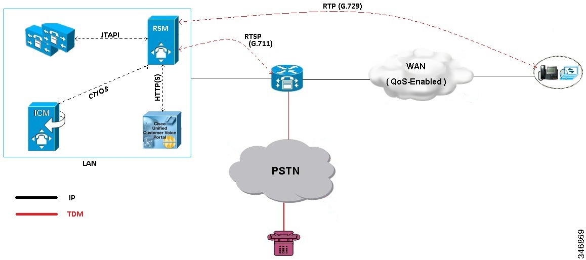
For Mobile Agents, the voice path crosses the Public Switched Telephone Network (PSTN) and two gateways.
One gateway control calls from customer phones. The other gateway controls calls from agents, known as agent gateway.In a Mobile Agent deployment, the Silent Monitor service uses a SPAN port to receive the voice traffic that passes through the agent gateway. This requires the computer running the Silent Monitor service to have two NIC cards; one to handle communications with clients and another to receive all traffic spanned from the switch.
For example, if the agent gateway is connected to port 1 and the NIC (on the Silent Monitor Server that receives SPAN traffic) is connected on port 10, use the following commands to configure the SPAN session:
monitor session 1 source interface fastEthernet0/1
monitor session 1 destination interface fastEthernet0/10
-
To deploy Silent Monitoring for the Mobile Agent, there must be two gateways; one gateway for agent traffic and another for caller traffic.
If you use one gateway for both agent and caller traffic, the voice traffic does not leave or cross the agent gateway and therefore cannot be silently monitored.For example, agent-to-agent and consultation calls between Mobile Agents share the same gateway and cannot be silently monitored. Most Mobile Agent deployments only allow silent monitoring for calls between agents and customers.
-
Install Silent Monitor service on the supervisors desktop, but you need not configure Silent Monitor service for the Mobile Agents. You must configure the agent to use one or more Silent Monitor Servers in the CTI OS Server setup program.
-
Agents who are both mobile and regular agents require at least two profiles.
The profiles for regular agents do not contain any Silent Monitor service information.
The profiles for Mobile Agents, contains information used to connect to a Silent Monitor Server.
Silent Monitor Service Clusters
If more than one agent gateway is present in the call center and an agent can use either gateway to log in, cluster the Silent Monitor services to support Silent Monitor as follows.
Deploy a separate silent monitor server for each gateway.
Configure a SPAN port for each silent monitor server as described in the previous section.
Run the Silent Monitor server installer to install and configure two Silent Monitor servers as peers.
Configure the following to set up a connection profile to instruct the agent desktops to connect to one of the peers:
Configurations for SPAN from Call Manager
Span from Call Manager is recommended for small agent contact center only as in this deployment model CUCM software resources are being used .
To Span from CUCM ensure that SM server should be on the same blade as CUCM. Ensure that CUCM uses its own mtp resources ,when the agent is logged into a phone across a gateway.
This requires the computer running the Silent Monitor service to have two NIC cards; one to handle communications with clients and another to receive all traffic spanned from the nexus.
Unified CCE AW-HDS-DDS
To install Unified CCE AW-HDS-DDS, see Create Golden Template for Unified CCE AW-HDS-DDS and to configure see Configure Unified CCE AW-HDS-DDS.
Cisco RSM
Create Golden Template for Cisco Remote Silent Monitoring
Follow this sequence of tasks to create the golden template for the Cisco RSM server.
After each task, return to this page to mark the task "done" and continue the sequence.
|
Sequence |
Done? |
Tasks |
Notes |
|---|---|---|---|
|
1 |
Download HCS-CC_11.0(1)_CCE-RSM_vmv9_v1.0.ova. |
See Open Virtualization Format Files. | |
|
2 |
Create the virtual machine for the Cisco RSM server. |
Follow the procedure Create Virtual Machines. |
|
|
3 |
Install Microsoft Windows Server |
Follow the procedure Install Microsoft Windows Server 2012 R2 Standard Edition. |
|
|
5 |
Install antivirus software. |
Follow the procedure Install Antivirus Software. |
|
|
6 |
Install the JTAPI Client. |
Follow the procedure Install the JTAPI Client. |
|
|
7 |
Configure SNMP Traps for Cisco RSM |
Follow the procedure Configuring SNMP Traps for Cisco RSM |
|
|
8 |
Install the Cisco RSM server. |
Follow the procedure Install the Cisco RSM Server. |
|
|
9 |
Convert the virtual machine to a template. |
Follow the procedure Convert the Virtual Machine to a Golden Template. |
After you create all golden templates, you can run the automation process (Automated Cloning and OS Customization). After you run the automation process, you can configure the Cisco RSM server on the destination system. See Configure Cisco RSM.
Install the JTAPI Client
Complete the following procedure to install JTAPI on the Cisco RSM server.
Install the Cisco RSM Server
Complete the following procedure to install the Cisco RSM Server.
| Step 1 | Mount the Cisco RSM ISO image to the virtual machine. For more information, see Mount and Unmount ISO Files. |
| Step 2 | Run the setup.exe file to install the RSM server. The RSM installer program starts and it displays the Cisco Remote Silent Monitoring(RSM) InstallShield window. |
| Step 3 | Click Next. It displays the Licence Agreement page. |
| Step 4 | In the Licence Agreement page, accept the License. Click Next. |
| Step 5 | In the service Login Information page, provide the administrator credentials of RSM Virtual machine. Click Next. |
| Step 6 | In the Launch Configuration Settings page, click Exit from the setup. Click Yes on the pop-up window. |
| Step 7 | Click Finish. |
What to Do Next
Configuring SNMP Traps for Cisco RSM
Simple Network Management Protocol (SNMP) traps may be raised from Cisco RSM by configuring Windows to send selected events to an SNMP monitor. This is achieved using a Windows utility called evntwin.exe. This utility converts events written to the Windows Event log into SNMP traps that are raised and forwarded by the Windows SNMP service to an SNMP management tool.
Complete the following procedures to configure SNMP traps for use with Cisco RSM:
Configure SNMP Agent in MIB
The following information is to connect the RSM SNMP Agent and to root the MIB Object.
Configure Cisco RSM
The following figure shows the configuration topology for Remote Silent Monitoring.
- Configure Cisco RSM for 500 and 1000 Agent Deployment
- Configure Cisco RSM for 4000 Agent Deployment
- Configure Cisco RSM for 12000 Agent Deployment
- Configure Cisco RSM for Small Contact Center Deployment
- Configure Cisco RSM for A-Law Codec
Configure Cisco RSM for 500 and 1000 Agent Deployment
Configure the Cisco RSM (Remote Silent Monitoring) Server for 500 and 1000 agent deployment in the distributed mode, in the following order:
| Required Software | Tasks |
|---|---|
| Configure RSM |
Set RSM Configuration Settings for 500 and 1000 Agent Deployment |
| Configure Gateway | |
| Configure Unified CVP | |
| Configure Unified CCE | |
| Configure Unified Call Manager | |
- Configure RSM
- Configure Gateway
- Configure Unified CVP
- Configure Unified CCE
- Configure Unified Communication Manager
Configure RSM
Set RSM Configuration Settings for 500 and 1000 Agent Deployment
| Step 1 | Complete the
Mail Server configuration settings:
|
| Step 2 | Complete the
Miscellaneous configuration settings:
|
| Step 3 | Define
Cluster configuration settings:
These settings are used to configure each Unified Communications Manager cluster with the agents to be monitored by RSM. |
| Step 4 | Define Unified Communications Manager configuration settings: |
| Step 5 | In UCCE
Integration page select UCCE integrate with CTIOS OR UCCE integrate with CTI
|
| Step 6 | Click Next and Check Start PhoneSim Service and Start VLEngine Service check boxes. |
| Step 7 | Click Finish. |
Configure JTAPI Client Preferences
Edit Registry Settings
RSM requires numeric supervisor accounts, so that users can log in through the telephone. However, Unified CCE supervisor agent accounts are also Active Directory user accounts and an Active Directory security policy can prevent numeric-only accounts. To resolve this issue, modify the "VLEngine_PassPrefix" parameter.
| Step 1 | Access the Registry Editor, Start > Run > regedit. | ||
| Step 2 | Navigate to HKEY_Local_Machine > Software > Wow6432Node > Cisco Systems, Inc. > Remote Silent Monitoring. | ||
| Step 3 | SetVLEngine_PassPrefix with a string that prepends the password
before it submits for CTI OS Validation.
For Example: If "VLEngine_PassPrefix" String is set to RSM1RSM and you want a supervisor to log in with PIN 1234, then set supervisor's password to RSM1RSM1234.
|
Configure Gateway
Set Up the VXML Gateway
RSM is supported on any VXML gateway models and versions of Cisco IOS supporting CVP. The Ingress/VXML gateway can be shared between RSM and other features.
To set up the VXML gateway for RSM, make sure that the IVR prompt memory is at least 8 Mb, by issuing the ivr prompt memory 8000 command.
 Note | If the gateway is shared with RSM along with other features, the gateway performance reduces by 20%. |
Configure Unified CVP
Upload RSM Prompts
| Step 1 | Navigate to your media server directory, at C:\inetpub\wwwroot\en-us\, and create a new directory labeled VL. |
| Step 2 | Navigate to your RSM server and copy prompts.zip from C:\ CiscoRSM\callflows and unzip the contents into the VL directory of the media server. |
| Step 3 | Right-click the VL directory, then click Properties. |
| Step 4 | Click the Security tab, click Advanced and click Change Permission. |
| Step 5 | Select Include inheritable permission from object's parent and Replace all child object permission with inheritable permissions from this object check-boxes. |
| Step 6 | Click OK and click Yes on the windows security pop up window. |
| Step 7 | Open your web browser and navigate to the VL directory of your media server, that is http://<SERVER IP>/en-us/VL. Ensure that the prompt files are listed and accessible. |
Integrate the CVP Call Flow
| Step 1 | Navigate to the C:\CiscoRSM\callflows\vxml-cvp folder on the RSM server. | ||||
| Step 2 | Copy all the contents from the folder to a directory that can be accessed by the desktop machine hosting Cisco Unified Call Studio software (for example, C:\RSM-Callflow). | ||||
| Step 3 | Launch the Call Studio. Navigate to File> Import> Call Studio>Existing Call Studio Project in the menu bar to import the RSM project into the workspace and click Next. | ||||
| Step 4 | Browse the vxml-cvp folder and click Finish. | ||||
| Step 5 | Navigate to the DoLogin page in the Callflow Editor Navigator pane for RSM Project. | ||||
| Step 6 | Select the SetBaseSessionVars element, and then click Data under Element Configuration. | ||||
| Step 7 | Modify the
VoiceXML
Variable settings for RSM Project as follows:
| ||||
| Step 8 | Click Save to save the RSM Project. | ||||
| Step 9 | Right-click RSM Project in the navigator pane then click Properties. | ||||
| Step 10 | Under Call Studio, click Audio Settings. | ||||
| Step 11 | Navigate to the Default Audio Path URI text field and enter the VL directory on your media server, for example, http://<cvp_media_server_IP_address>/en-us/VL . Click OK. | ||||
| Step 12 | Repeat the
above steps to create RSM project for each CVP Server in your deployment.
|
Call Flow Deployment
Once the call flow script is installed on the CVP server, it must be deployed for use by CVP VXML Server.
Perform the procedure to deploy the call flow script.
Note | Deploy the VXML script in all the CVP boxes with the appropriate CVP_VXMLSVR_HOSTNAME |
| Step 1 | Open Cisco Unified Call Studio. |
| Step 2 | Right-click RSM Project in the navigator pane, then click Deploy. |
| Step 3 | Select Archive File radio button. |
| Step 4 | Browse to the loction where you want to save the VXML Application file. |
| Step 5 | Click Finish. The call flow script will be saved at the specified location. |
| Step 6 | Open the CVP OAMP portal. |
| Step 7 | Navigate to Bulk Administration > File Transfer > VXML application. |
| Step 8 | Choose the desired CVP VXML servers from Available to Selected and browse the VXML application file that you saved in step 4. |
| Step 9 | Click Transfer and click File Transfer Status to check the status. |
| Step 10 | Go to the SCC-CVP-SVR-A server and navigate to the C:\Cisco\CVP\VXMLServer\applications\RSM\admin Directory in CVP call server, then double-click the deployApp.bat file. The batch file is executed in a separate DOS window. |
| Step 11 | Enter Y for yes when prompted to deploy the application. The call flow script is now accessible from the CVP VXML Server. |
| Step 12 | Configure the appropriate micro applications on your VXML gateway (VXML Gateway dial peers, Unified Communication Manager route patterns, and so on) so they can access the script. |
Configure Unified CCE
Set the Agent Target Rule
Note | Ignore this procedure, if Unified CCE Day 1 configuration includes the Extension range. |
| Step 1 | From the Administration Workstation (AW), click Start > All Programs > Configuration Manager. | ||
| Step 2 | Expand Tools, then expand List Tools. Double-click Agent Targeting Rule. | ||
| Step 3 | Click Retrieve to return a list of all existing agent targets in the environment. | ||
| Step 4 | Highlight the existing agent targeting rule. Under extension ranges click Add. A blank extension range section appears. | ||
| Step 5 | Add the range of extension, that is the DN and then click OK. | ||
| Step 6 | Click
Save.
|
Create the Supervisor Login Account
You must create a new account for each supervisor who will be using RSM, according to your current CTI OS supervisor/agent accounts. If CTI OS authentication is used, separate supervisor agent accounts must be created in the Unified CCE environment, to allow dialed-in supervisors to log in to the system.
To create a supervisor login account, follow this procedure Create an Agent
Note |
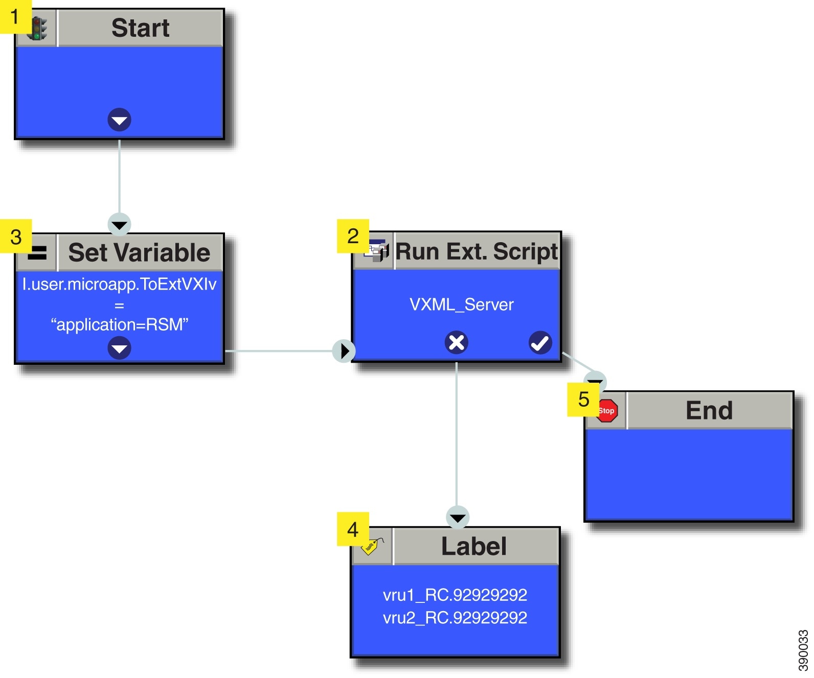
Create Routing Script for RSM
The following Routing Scripts are used for Cisco RSM.
Configure Unified Communication Manager
Configure Simulated Phone
You must determine the number of simulated phones ( also called as simphones) to assign to each Unified Communication Manager cluster. Each cluster must have a number of simphones greater than or equal to the maximum number of agents that will be simultaneously monitored through RSM for the cluster. This section provides the following information:
Perform the following steps to add new cluster in RSM:
Create Simphone Device Dependencies
Perform the below steps to create Simphone device dependencies:
Create Simphone Device
Perform the below steps to create Simphone devices:
-
Disable Built-in Bridge see, Enable or Disable the Built-in-Bridge
Set Up the Login Pool Simphone
The first five simphone devices that are created for each cluster are automatically assigned to the VLEngine login pool. The login pool performs a test login to CTI OS when a caller is authenticated by RSM, to support the VLEngine authentication mechanism. Because CTI OS logins are performed on these simphone devices, they must be associated with the pguser account on each Unified Communications Manager cluster. They must also have Cisco Unified Intelligent Contact Management Enterprise device targets created.
Associate first five phones
to application user. see,
Associate Phone to Application User
.
Configure Cisco RSM for 4000 Agent Deployment
Configure the Cisco RSM (Remote Silent Monitoring) Server for 4000 agent deployment in the distributed mode, in the following order:
| Required Software | Tasks |
|---|---|
| Configure RSM |
Set RSM Configuration Settings for 4000 and 12000 Agent Deployment |
| Configure Gateway | |
| Configure Unified CVP | |
| Configure Unified CCE | |
| Configure Unified Call Manager | |
Set RSM Configuration Settings for 4000 and 12000 Agent Deployment
| Step 1 | Complete the
Mail Server configuration settings:
| ||
| Step 2 | Complete the
Miscellaneous configuration settings:
| ||
| Step 3 | Define first
Cluster configuration settings:
These settings are used to configure the Unified Communications Manager cluster with the agents to be monitored by RSM. | ||
| Step 4 | Define Unified Communications Manager configuration settings for first cluster: | ||
| Step 5 | In UCCE Integration page select UCCE integrate with CTI | ||
| Step 6 | Define
second Cluster configuration settings:
These settings are used to configure the Unified Communications Manager cluster with the agents to be monitored by RSM. | ||
| Step 7 | In UCCE Integration page select UCCE integrate with CTI | ||
| Step 8 | Check Start PhoneSim Service and Start VLEngine Service check boxes. | ||
| Step 9 | Click
Finish.
|
Configure Cisco RSM for 12000 Agent Deployment
Configure the Cisco RSM (Remote Silent Monitoring) Server for 12000 agent deployment in the distributed mode, in the following order:
| Required Software | Tasks |
|---|---|
| Configure RSM |
Set RSM Configuration Settings for 4000 and 12000 Agent Deployment |
| Configure Gateway | |
| Configure Unified CVP | |
| Configure Unified CCE | |
| Configure Unified Call Manager | |
Configure Cisco RSM for Small Contact Center Deployment
Configure the Cisco RSM (Remote Silent Monitoring) Server for Small Contact Center deployment in the distributed mode, in the following order.
Note | Each Sub customer will have Individual RSM configured. |
| Required Software | Tasks |
|---|---|
| Configure RSM |
Set RSM Configuration Settings for Small Contact Center Deployment |
| Configure Gateway | |
| Configure Unified CVP | |
| Configure Unified CCE | |
| Configure Unified Call Manager | |
Set RSM Configuration Settings for Small Contact Center Deployment
| Step 1 | Complete the
Mail Server configuration settings:
|
| Step 2 | Complete the
Miscellaneous configuration settings:
|
| Step 3 | Define
Cluster configuration settings:
These settings are used to configure the Unified Communications Manager cluster with the agents to be monitored by RSM. |
| Step 4 | Define Unified Communications Manager configuration settings for the cluster: |
| Step 5 | Select UCCE Integration with CTI in UCCE Integration window and enter the following: |
| Step 6 | Check Start PhoneSim Service and Start VLEngine Service check boxes. |
| Step 7 | Click Finish. |
Configure Cisco RSM for A-Law Codec
Configure RSM
For more information about configuring Cisco RSM, see Configure RSM.
Note | Ensure that you select rtsp-alaw for Miscellaneous configuration settings (Step 2-k) in RSM configuration. |
Configure Gateway
For more information, see Configure Gateway.
Configure Unified CVP
For more information, see Configure Unified CVP.
Configure Unified Communications Manager
Configure Service Parameters
For more information, see Configure Unified Communication Manager.
Cisco MediaSense
Create Golden Template for Cisco MediaSense
| Sequence | Done? | Tasks | Notes |
| 1 |
Download cms_11.0_vmv8_v1.0.ova. |
||
| 2 |
Create the virtual machine from the OVA. |
Follow the procedure that is documented in, Create Virtual Machines. |
|
| 3 |
Install Cisco MediaSense. |
Follow the procedure for installing VOS applications for golden templates. See Install Unified Communications Voice OS based Applications. |
|
| 4 |
Convert the virtual machine to a Golden Template. |
Follow the procedure Convert the Virtual Machine to a Golden Template. |
After creating all the golden templates, you can run the automation process Automated Cloning and OS Customization. After you run the automation process, you can configure Cisco MediaSense on the destination system. See Configure Cisco MediaSense.
Configure Cisco MediaSense
Cisco MediaSense Primary
Configure Cisco MediaSense Primary
If there is a value in the optional DNS_IP_NIC1 cell of the automation spreadsheet, configure the DNS server by adding the machine in forward and reverse lookup. For more information, see Configure DNS Server.
| Step 1 | Ensure that Connect at Power On is checked for the network adapters and the floppy drive and click OK. | ||
| Step 2 | Power on the Primary. This begins the installation based on the information in the .flp file. The installation begins automatically and runs with no interaction from you. After an hour or more, a message appears indicating a successful installation. | ||
| Step 3 | Click the Console tab for the VM. Log in to the publisher machine, using the credentials for the Administration User. The machine opens to the CLI interface. | ||
| Step 4 | Edit settings
and uncheck
Connect at Power on for the floppy drive.
After rebooting, the VM installation is complete with all the parameters provided in the spreadsheet for the VM. |
Complete Setup for Primary Server
Follow this procedure to complete the setup for the primary server in any MediaSense deployment:
| Step 1 | After you complete the installation procedure, the system automatically restarts. Sign in to MediaSense Administration for the primary server. (https://<server>:8443/oraadmin) Welcome screen of the MediaSense First Server Setup wizard is displayed. |
| Step 2 | When you are ready to proceed, click Next. The Service Activation screen is displayed. |
| Step 3 | The system internally verifies the IP address of this server and automatically begins enabling the MediaSense feature services in this server. Wait until all the features services show as enabled in the Service Activation window. After all the services are successfully enabled, click Next. After you click Next, the AXL Service Provider screen appears. |
| Step 4 | Enter the AXL service provider (IP address) and the AXL administrator username and password in the respective fields for the Unified CM that should communicate with MediaSense and click Next, the Call Control Service Provider screen appears. The AXL authentication allows you to enter the Unified CM cluster and retrieve the list of Unified CM servers within that cluster. The AXL administrator username may not be same as the Unified CM Administrator username for that cluster. Make sure to add the username for the AXL Administrator to the Standard Unified CM Administrators group and “Standard AXL API Access” roles in Unified CM. |
| Step 5 | Select and move the Unified CM IP address for Call Control Service from Available Call Control Service Providers window to Selected Call Control Service Providers window and click Next. |
| Step 6 | The MediaSense
Setup Summary window appears with successfully configured services. Click Done
to complete the initial setup for the primary server.
When you finish the post-installation process for any MediaSense server, you must access the Unified CM server for your deployment and you will need to configure the SIP trunk, route pattern, route group, route list, recording profile and end user. You have now completed the initial setup of the primary server for MediaSense. Before you install MediaSense on a secondary server or an expansion server, you must configure details for these servers on the primary server. You configure details for these servers using the MediaSense Administration user interface. |
| Step 7 | Login to MediaSense Administration > API User Configuration |
| Step 8 | Select the
available Unified CM User and add it to MediaSense API Users list.
Using this user you can login to Search and Play. |
What to Do Next
Configure Incoming Call
Cisco MediaSense Secondary
If there is a value in the optional DNS_IP_NIC1 cell of the automation spreadsheet, configure the DNS server by adding the machine in forward and reverse lookup. See Configure DNS Server.
| Step 1 | Ensure that Connect at Power on is checked for the network adapters and the floppy drive and click OK. |
| Step 2 | Power on the Secondary. This begins the installation based on the information in the .flp file. The installation begins automatically and runs with no interaction from you. After an hour or more, a message appears indicating a successful installation. |
| Step 3 | Click the Console tab for the VM. Log in to the secondary machine, using the credentials for the Administration User. The machine opens to the CLI interface. |
| Step 4 | Right-click
the VM and choose
Edit
settings
and uncheck
Connect at Power on for the floppy drive.
During the customization of the secondary node, the username and the password are modified as follows. The customer should change the password.
After rebooting, the VM installation is complete with all the parameters provided in the spreadsheet for theVM. |
Add Secondary Node
| Step 1 | Login to the web portal of MediaSense | ||
| Step 2 | From the System menu on the left, select MediaSense Server Configuration. | ||
| Step 3 | In the MediaSense Server Configuration screen, click Add MediaSense Server. The Add MediaSense Server screen in the primary node opens. | ||
| Step 4 | If your installation uses DNS suffixes, enter the hostname of the server that you want to add. | ||
| Step 5 | If your installation does not use DNS suffixes, enter the IP address of the server that you want to add. | ||
| Step 6 | Enter the description of the server that you want to add (Optional). | ||
| Step 7 | Enter the MAC address of the server that you want to add (Optional). | ||
| Step 8 | Click Save. | ||
| Step 9 | Click
Back
to MediaSense Server List.
MediaSense displays a confirmation message. You see the configuration details of the server that you added in the MediaSense Server List.
|
Configure Cisco MediaSense Secondary
If there is a value in the optional DNS_IP_NIC1 cell of the automation spreadsheet, configure the DNS server by adding the machine in forward and reverse lookup. See Configure DNS Server.
| Step 1 | In the client computer where the automation tool was run, navigate to C:\GoldenTemplateTool_10\PlatformConfigRepository\MediaSense. | ||
| Step 2 | Copy the file named MEDIASENSE_SECONDARY_platformConfig.xml. | ||
| Step 3 | Paste it to another location and rename it to platformConfig.xml. | ||
| Step 4 | Launch WinImage and select and click OK. | ||
| Step 5 | Drag and
drop
platformConfig.xmlinto WinImage.
| ||
| Step 6 | Open vSphere infrastructure client and connect to the vCenter. Go to the customer ESXi host where the VMs are deployed. | ||
| Step 7 | Navigate to the Configuration tab and in the storage section right click on the Datastore and choose Browse Datastore. | ||
| Step 8 | Create the folder CMS_SEC and upload platformConfig.flp to it. | ||
| Step 9 | Edit the Virtual Machine settings for the Unified Communications Manager Subscriber VM. | ||
| Step 10 | On the Hardware tab, click the floppy drive, choose the radio button Use The Existing Floppy Image in Datastore and mount the platformConfig.flp from the CMS_SEC folder on the data store. | ||
| Step 11 | Ensure that Connect at Power On is checked for the network adapters and the floppy drive. Click OK and then power on the VM. This begins the installation and customizes the installation based on the information in the .flp file. | ||
| Step 12 | If there is
a value in the optional DNS_IP_NIC1 cell of the automation spreadsheet,
configure the DNS server by adding the machine in forward and reverse lookup.
| ||
| Step 13 | After you
complete the installation uncheck
Connect at Power on for the floppy drive.
After rebooting, the VM installation is complete with all the parameters provided in the spreadsheet for the VM. |
Complete Setup for Secondary Server
Follow this procedure to complete the setup for the secondary server in any MediaSense deployment:
| Step 1 | After you complete the installation procedure of the previous section, the system restarts automatically and you must sign in to MediaSense Administration for secondary servers. When you sign in, the Welcome screen of the MediaSense Secondary Server Setup wizard appears. |
| Step 2 | When you are
ready to proceed, click
Next.
You determine the type of server in this Welcome screen. Select the server type Secondary and click Next. The Service Activation screen is displayed. |
| Step 3 | After the
services are enabled, click
Finish to complete the initial setup for a
subsequent server.
The MediaSense Setup Summary window displays the result of the initial setup and MediaSense restarts. You have now completed the initial setup of a subsequent server. This subsequent server is ready to record. Repeat this setup procedure for each expansion server in the cluster. |
Configure MediaSense Forking
- Provisioning Cisco Unified CM for Cisco MediaSense BIB Forking
- Provisioning Cisco Unified Border Element for Cisco MediaSense CUBE Forking
- Provisioning TDM Gateway for Media Forking
Provisioning Cisco Unified CM for Cisco MediaSense BIB Forking
| Sequence | Task | Done? |
|---|---|---|
| 1 | Set Up SIP Options | |
| 2 | Add SIP Trunks | |
| 3 | Add Route Pattern | |
| 4 | Set up Recording Profile | |
| 5 | Configure Device | |
| 6 | Disable iLBC, iSAC and g.722 for Recording Device | |
| 7 | Configure End User |
Configure Device
| Step 1 | Login to Cisco Unified Communication Domain Manager as provider. | ||
| Step 2 | Ensure that hierarchy is set to appropriate customer level. | ||
| Step 3 | Navigate to . | ||
| Step 4 | Choose the phone from the list that you want to configure. | ||
| Step 5 | Choose ON from Built-in Bridge drop-down list to enable Built-in Bridge. | ||
| Step 6 | In Lines tab, choose Automatic Call Recording Enabled from Recording Flag drop-down list. | ||
| Step 7 | Enter
Recording Profile Name.
| ||
| Step 8 | Click Save. |
Configure End User
| Step 1 | Login to Cisco Unified Communication Domain Manager as provider, reseller or customer admin. |
| Step 2 | Ensure that hierarchy is set to appropriate customer/site. |
| Step 3 | Navigate to . |
| Step 4 | Click Add. |
| Step 5 | Enter unique Userid and Last Name, in User tab. |
| Step 6 | Enter Password and Repeat Password. |
| Step 7 | Click Save. |
Provisioning Cisco Unified Border Element for Cisco MediaSense CUBE Forking
- Provisioning Cisco Unified Border Element for Cisco MediaSense CUBE Forking for HCS Deployment Models
- Provisioning Cisco Unified Border Element for Cisco MediaSense CUBE Forking for SCC Deployment Models
Provisioning Cisco Unified Border Element for Cisco MediaSense CUBE Forking for HCS Deployment Models
| Sequence | Task | Done? |
|---|---|---|
| 1 | Setup Global Level | |
| 2 | Dial-Peer Level Setup | |
| 3 | Set Up CUBE Dial-Peers for MediaSense Deployments |
Setup Global Level
| Step 1 | Connect to your CUBE gateway using SSH or Telnet. | ||
| Step 2 | Enter the
global configuration mode.
cube# configure terminal Enter configuration commands, one per line. End with CNTL/Z. cube(config)# | ||
| Step 3 | Enter VoIP
voice-service configuration mode.
cube(config)# voice service voip cube(config-voi-serv)# | ||
| Step 4 | Calls may be
rejected with a 403 Forbidden response if Toll Fraud security is not configured
correctly. The solution is to add the IP address as a trusted endpoint, or else
disable the IP address trusted list authentication altogether using the
following configuration entry:
cube(config-voi-serv)# no ip address trusted authenticate | ||
| Step 5 | Enable CUBE
and CUBE Redundancy.
cube(config-voi-serv)# mode border-element
cube(config-voi-serv)# allow-connections sip to sip
cube(config-voi-serv)# sip
cube(config-voi-serv)# asymmetric payload full
cube(config-voi-serv)# video screening
In the example above, the final 3 lines are only required if video calls are to be passed through CUBE. | ||
| Step 6 | At this point,
you will need to save the CUBE configuration and reboot CUBE.
| ||
| Step 7 | After you
reboot CUBE, configure the media class to determine which calls should be
recorded.
cube(config-voi-serv)# media class 3 cube(config-voi-serv)# recorder parameter cube(config-voi-serv)# media-recording 3000 | ||
| Step 8 | Exit the VoIP
voice-service configuration mode.
cube(config-voi-serv)# exit | ||
| Step 9 | Create one
voice codec class to include five codecs (including one for video). These
codecs will be used by the inbound and outbound dial-peers to specify the voice
class.
cube(config)# voice class codec 3
cube(config)# codec preference 1 mp4a-latm
cube(config)# codec preference 2 g711ulaw
cube(config)# codec preference 3 g722-64
cube(config)# codec preference 4 g729br8
cube(config)# video codec h264
In the example above, the first codec preference and video codec definition are only required if AAC-LD/LATM media is part of the customer's call flow. | ||
| Step 10 | To simplify
debugging, you must synchronize the local time in CUBE with the local time in
Cisco MediaSense servers. For example, if you specify the NTP server as
10.10.10.5, then use the following command in CUBE:
cube(config)# ntp update-calendar cube(config)# sntp server 10.10.10.5 |
Dial-Peer Level Setup
Note | This information describes a sample configuration. CUBE may be deployed in multiple ways. |
Before you begin this procedure, obtain the details for these three dial-peers from your CUBE administrator.
Note | The order in which you configure these three dial-peers is not important. |
Set Up CUBE Dial-Peers for MediaSense Deployments
 Caution | This procedure is not a substitute for the actual CUBE documentation. It is a tutorial to provide detailed information about configuring CUBE for MediaSense. See your CUBE documentation at http://www.cisco.com/go/cube for the latest information. |
Provisioning Cisco Unified Border Element for Cisco MediaSense CUBE Forking for SCC Deployment Models
| Sequence | Task | Done? |
|---|---|---|
| 1 | Setup Global Level | |
| 2 | Dial-Peer Level Setup | |
| 3 | Set Up CUBE Dial-Peers for Small Contact Center Deployment |
Set Up CUBE Dial-Peers for Small Contact Center Deployment
The inbound dialpeer for MediaSense should be created for each sub customer . Follow the below steps to create the inbound dialpeer:
Provisioning TDM Gateway for Media Forking
The following section will provide detailed guidelines on how to configure media recording for calls on TDM trunks. CUBE (E), being an integrated platform can provide TDM trunk connectivity and act as a session border controller at the same time.
For this solution to work, calls from the PSTN are looped back to itself thus creating an inbound VoIP SIP leg to the CUBE. It then sends the call to the call agent in the enterprise network creating an outbound VoIP SIP leg. Thus, the gateway is used to terminate the TDM leg, and originate an IP leg towards the call agent.
Note | In this flow ,calls will effectively halve the stated capacity of the router, thus requiring twice as much router capacity for the same number of calls. If you intended to use the full capacity of the router for calls, you will need two routers. It is better to configure two routers for their individual purposes, rather than using both routers for both purposes. |
| Sequence | Task | Done? |
|---|---|---|
| 1 | Configure translation rule and profile | |
| 2 | Configure loopback interface | |
| 3 | Configure media class | |
| 4 | Configure dial-peers |
| Step 1 | Configure
translation rule and profile
|
| Step 2 | Configure
loopback interface
interface Loopback0 ip address 1.1.1.1 255.255.255.255 |
| Step 3 | Configure
media class
Configure
the media class to determine which calls should be recorded.
cube(config-voi-serv)# media class 3 cube(config-voi-serv)# recorder parameter cube(config-voi-serv)# media-recording 20 |
| Step 4 | Configure
dial-peers
|
Cisco Unified SIP Proxy
- Install Cisco Unified SIP Proxy
- Configure Cisco Unified SIP Proxy Server
- Configure Outbound with Cisco Unified SIP Proxy
Install Cisco Unified SIP Proxy
Installation of CUSP
| Step 1 | Download all Cisco Unified SIP Proxy 8.5.7 software files. |
| Step 2 | Copy the files to the FTP server. |
| Step 3 | Starting from
router EXEC mode, enter the following:
ping <ftp_server_ip_address> |
| Step 4 | Enter the
following and Install the software:
Service-Module 1/0 install url ftp://<ftp_server_ip_address>/cusp-k9.sme.8.5.7.pkg |
| Step 5 | Enter Y to confirm installation. |
| Step 6 | Enter Cisco Unified SIP Proxy Service Module to monitor and complete the installation. |
Example of Installation on a Service Module
CUSP#service-nodule SM4/0 inst
CUSP#$ule SM4/0 install url ftp://10.10.10.203/cusp-k9.snc.8.5.7.pkg
Delete the installed Cisco Unified SIP Proxy and proceed with new installation?
[no]:yes
Loading cusp-k9.snc.8.5.7.pkg.install.src !
[OK – 1850/4096 bytes]
cur_cpu: 1862
cur_disk: 953880
cur_nem: 4113488
cur_pkg_name: cusp-k9.sne.8.5.7.pkg
cur_ios_version: 15.2<4>M5,
cur_image_name:c3900e-universalk9-mz
cur_pid: SM-SRE-900-K9
bl_str:
inst_str:
app_str:
key_filename: cusp-k9.sne.8.5.7.key
helper_filename:cusp-helper.sme.8.5.7
Resource check passed…
Post Installation Configuration Tool
Run the command: CUSP#service-module SM 4/0 session to open the first session.
When you open the first session, the system launches the post installation configuration tool, and asks you if you want to start configuration immediately.
Enter the appropriate response, y or n. If you enter n, the system will halt. If you enter "y", the system will ask you to confirm, then begin the interactive post installation configuration process.
The following is an example:
IMPORTANT::
IMPORTANT:: Welcome to Cisco Systems Service Engine
IMPORTANT:: post installation configuration tool.
IMPORTANT::
IMPORTANT:: This is a one time process which will guide
IMPORTANT:: you through initial setup of your Service Engine.
IMPORTANT:: Once run, this process will have configured
IMPORTANT:: the system for your location.
IMPORTANT::
IMPORTANT:: If you do not wish to continue, the system will be halted
IMPORTANT:: so it can be safely removed from the router.
IMPORTANT::

Do you wish to start configuration now (y,n)? yes
Are you sure (y,n)? yes

IMPORTANT::
IMPORTANT:: A configuration has been found in flash. You can choose
IMPORTANT:: to restore this configuration into the current image.
IMPORTANT::
IMPORTANT:: A stored configuration contains some of the data from a
IMPORTANT:: previous installation, but not as much as a backup.
IMPORTANT::
IMPORTANT:: If you are recovering from a disaster and do not have a
IMPORTANT:: backup, you can restore the saved configuration.
IMPORTANT::
IMPORTANT:: If you choose not to restore the saved configuration, it
IMPORTANT:: will be erased from flash.
IMPORTANT::

Would you like to restore the saved configuration? (y,n) n

Erasing old configuration...done.

IMPORTANT::
IMPORTANT:: The old configuration has been erased.
IMPORTANT:: As soon as you finish configuring the system please use the
IMPORTANT:: "write memory" command to save the new configuration to flash.
IMPORTANT::

Enter Hostname
(my-hostname, or enter to use se-10-50-30-125):
Using se-10-50-30-125 as default

Enter Domain Name
(mydomain.com, or enter to use localdomain): cusp

IMPORTANT:: DNS Configuration:
IMPORTANT::
IMPORTANT:: This allows the entry of hostnames, for example foo.cisco.com, instead
IMPORTANT:: of IP addresses like 1.100.10.205 for application configuration. In order
IMPORTANT:: to set up DNS you must know the IP address of at least one of your
IMPORTANT:: DNS Servers.

Would you like to use DNS (y,n)?y

Enter IP Address of the Primary DNS Server
(IP address): 180.180.180.50
Found server 180.180.180.50

Enter IP Address of the Secondary DNS Server (other than Primary)
(IP address, or enter to bypass):

E

Enter Fully Qualified Domain Name(FQDN: e.g. myhost.mydomain.com)
or IP address of the Primary NTP server
(FQDN or IP address, or enter for 10.50.30.1): 10.50.10.1
Found server 10.50.10.1

Enter Fully Qualified Domain Name(FQDN: e.g. myhost.mydomain.com)
or IP address of the Secondary NTP Server
(FQDN or IP address, or enter to bypass):

Please identify a location so that time zone rules can be set correctly.
Please select a continent or ocean.
1) Africa 4) Arctic Ocean 7) Australia 10) Pacific Ocean
2) Americas 5) Asia 8) Europe
3) Antarctica 6) Atlantic Ocean 9) Indian Ocean
#? 2
Please select a country.
1) Anguilla 27) Honduras
2) Antigua & Barbuda 28) Jamaica
3) Argentina 29) Martinique
4) Aruba 30) Mexico
5) Bahamas 31) Montserrat
6) Barbados 32) Netherlands Antilles
7) Belize 33) Nicaragua
8) Bolivia 34) Panama
9) Brazil 35) Paraguay
10) Canada 36) Peru
11) Cayman Islands 37) Puerto Rico
12) Chile 38) St Barthelemy
13) Colombia 39) St Kitts & Nevis
14) Costa Rica 40) St Lucia
15) Cuba 41) St Martin (French part)
16) Dominica 42) St Pierre & Miquelon
17) Dominican Republic 43) St Vincent
18) Ecuador 44) Suriname
19) El Salvador 45) Trinidad & Tobago
20) French Guiana 46) Turks & Caicos Is
21) Greenland 47) United States
22) Grenada 48) Uruguay
23) Guadeloupe 49) Venezuela
24) Guatemala 50) Virgin Islands (UK)
25) Guyana 51) Virgin Islands (US)
26) Haiti
#? 47
Please select one of the following time zone regions.
1) Eastern Time
2) Eastern Time - Michigan - most locations
3) Eastern Time - Kentucky - Louisville area
4) Eastern Time - Kentucky - Wayne County
5) Eastern Time - Indiana - most locations
6) Eastern Time - Indiana - Daviess, Dubois, Knox & Martin Counties
7) Eastern Time - Indiana - Pulaski County
8) Eastern Time - Indiana - Crawford County
9) Eastern Time - Indiana - Pike County
10) Eastern Time - Indiana - Switzerland County
11) Central Time
12) Central Time - Indiana - Perry County
13) Central Time - Indiana - Starke County
14) Central Time - Michigan - Dickinson, Gogebic, Iron & Menominee Counties
15) Central Time - North Dakota - Oliver County
16) Central Time - North Dakota - Morton County (except Mandan area)
17) Mountain Time
18) Mountain Time - south Idaho & east Oregon
19) Mountain Time - Navajo
20) Mountain Standard Time - Arizona
21) Pacific Time
22) Alaska Time
23) Alaska Time - Alaska panhandle
24) Alaska Time - Alaska panhandle neck
25) Alaska Time - west Alaska
26) Aleutian Islands
27) Hawaii
#? 21

The following information has been given:
United States
Pacific Time

Therefore TZ='America/Los_Angeles' will be used.
Is the above information OK?
1) Yes
2) No
#? 1

Local time is now: Mon Apr 5 11:20:17 PDT 2010.
Universal Time is now: Mon Apr 5 18:20:17 UTC 2010.
executing app post_install
executing app post_install done
Configuring the system. Please wait...
Changing owners and file permissions.
Tightening file permissions ...
Change owners and permissions complete.
Creating Postgres database .... done.
INIT: Switching to runlevel: 4
INIT: Sending processes the TERM signal
==> Starting CDP
STARTED: cli_server.sh
STARTED: ntp_startup.sh
STARTED: LDAP_startup.sh
STARTED: SQL_startup.sh
STARTED: dwnldr_startup.sh
STARTED: HTTP_startup.sh
STARTED: probe
STARTED: fndn_udins_wrapper
STARTED: superthread_startup.sh
STARTED: /bin/products/umg/umg_startup.sh

Waiting 49 ...

IMPORTANT::
IMPORTANT:: Administrator Account Creation
IMPORTANT::
IMPORTANT:: Create an administrator account.
IMPORTANT:: With this account, you can log in to the
IMPORTANT:: Cisco Unified SIP Proxy
IMPORTANT:: GUI and run the initialization wizard.

IMPORTANT::

Enter administrator user ID:
(user ID): test
tesEnter password for test:
(password):
Confirm password for test by reentering it:
(password):

SYSTEM ONLINE
cusp-sre-49# show software version
Cisco Unified SIP Proxy version <8.5.7>
Technical Support: http://www.cisco.com/techsupport Copyright <c> 1986-2008 by Cisco Systems,Inc.
Cusp-src-49# show software packages

Installed Packages:
-	Installer <Installer application >  <8.5.7.0>
-	Infrastructure <Service Engine Infrastructure> <8.5.7>
-	Global <Global manifest > <8.5.7>
-	Bootloader <Secondary> <Service Engine Bootloader> <2.1.30>
-	Core <Service Engine OS Core > <8.5.7>
-	GPL Infrastrucutre <Service Engine GPL Infrastructure > <8.5.7>
Obtaining New or Additional Licenses
- Required Information
- Using the Licensing Portal to Obtain Licenses for Additional Features or Applications
- Using the CLI to Install the Cisco Unified SIP Proxy Release 8.5.7 Licenses
Required Information
-
The SKU for the features that you need. The SKU is used in the ordering process to specify the desired licenses for the Cisco Unified SIP Proxy features that you want.
-
The Product ID (PID) and the Serial Number (SN) from the device. Together, these form the unique device identifier (UDI). The UDI is printed on a label located on the back of most Cisco hardware devices or on a label tray visible on the front panel of field-replaceable motherboards. The UDI can also be viewed via software using the show license udi command in privileged EXEC mode.
Using the Licensing Portal to Obtain Licenses for Additional Features or Applications
Note | You must have a Cisco.com password to access some of the URLs in the following procedure. |
Follow these steps to obtain additional licenses for Cisco Unified SIP Proxy Release 8.5.7 features.
| Step 1 | Go to http://www.cisco.com/web/ordering/root/index.html and choose one of the ordering processes (through partner, Cisco direct, etc.) and order licenses. When you purchase a license, you will receive a product activation key (PAK), which is an alphanumeric string that represents the purchase. |
| Step 2 | To get your license file, return to the Cisco Product License Registration Portal at http://www.cisco.com/web/ordering/root/index.html. When prompted, and enter the PAK and the unique device identifier (UDI) of the device where the license will be installed. |
| Step 3 | Download the license file or receive the license file by email. |
| Step 4 | Copy the license file(s) to a FTP or TFTP server. |
Using the CLI to Install the Cisco Unified SIP Proxy Release 8.5.7 Licenses
Follow these steps to install the licenses for Cisco Unified SIP Proxy
| Step 1 | Login to the CLI. | ||
| Step 2 | Enter license install <URL>, where <URL> is the FTP URL that you copied the license in the previous procedure. | ||
| Step 3 | Verify the license by entering either show license or show software licenses. | ||
| Step 4 | Activate the new license by entering license activate. | ||
| Step 5 | Reload the
module by entering
reload and confirming that you really want to reload
the module.
|
Configure Cisco Unified SIP Proxy Server
Login to CUSP portal http://<cusp module IP>/admin/Common/HomePage.do and configure the Cisco Unified SIP Proxy server, in the following order:
| Required Software | Tasks |
|---|---|
| Configure CUSP | |
| Configure Gateway | |
| Configure Unified CVP | |
| Configure Unified Call Manager though UCDM |
- Configure Cisco Unified SIP Proxy
- Configure Gateway
- Configure Unified CVP
- Configure Cisco Unified Communications Manager
Configure Cisco Unified SIP Proxy
Perform the following procedures to configure Unified SIP Proxy
| Sequence | Done? | Tasks | Notes |
|---|---|---|---|
|
1 |
|||
|
2 |
|||
|
3 |
|||
|
4 |
|||
|
5 |
|||
|
6 |
For complete configuration details of Cisco Unified SIP Proxy, see Full Configuration for Cisco Unified SIP Proxy
| Server Name | IP Address | FQDN |
|---|---|---|
| CUSP | 10.10.10.49 | cusp.hcsdc1.icm |
| CVP | 10.10.10.10 | cvp.hcsdc1.icm |
| CUCM | 10.10.10.30 | ccm.hcsdc1.icm |
| Gateway | 10.10.10.180 | gw.hcsdc1.icm |
- Configure Networks
- Configure Triggers
- Configure Server Groups
- Configure Route Tables
- Configure Route Policies
- Configure Route Triggers
- Full Configuration for Cisco Unified SIP Proxy
Configure Networks
| Step 1 | Login to CUSP portal. |
| Step 2 | Navigate to and click Add. |
| Step 3 | Enter a unique
name for the Network.
Example:hcs |
| Step 4 | Choose Standard from the TYPE drop-down list. |
| Step 5 | Enable the Allow Outbound Connections. |
| Step 6 | Click Add on the SIP Listen Points tab. |
| Step 7 | Choose newly added Network and select SIP Listen Points tab. |
| Step 8 | Select the IP address of the CUSP, from the IP address drop-down list, See Table 1. |
| Step 9 | Keep the default port 5060. |
| Step 10 | Select the Transport Type as TCP and click Add. |
| Step 11 | Repeat the step 6 to step 8, select Transport Type as UDP and click Add. |
| Step 12 | Disable SIP Record-Route, select and disable all the networks for the CVP that includes callflows. |
Configure Triggers
Configure Server Groups
| Step 1 | Login to CUSP portal. |
| Step 2 | Navigate to . |
| Step 3 | Enter a name
(FQDN) for the
Server Group.
Example:ccm.hcsdc1.icm |
| Step 4 | Choose global (default) from Load Balancing Scheme drop-down list. |
| Step 5 | Choose hcs from Network drop-down list. |
| Step 6 | Check the Pinging Allowed check-box. |
| Step 7 | Click Add. |
| Step 8 | Select newly added Server Group to add the elements for a respective server group. |
| Step 9 | Select Elements tab and click Add. |
| Step 10 | In <IP Address> text-box, enter the IP address of the Server Group, see Table 1. |
| Step 11 | In Port text-box, enter the port value. |
| Step 12 | Choose tcp from Transport Type drop-down list. |
| Step 13 | In Q-Value text-box, enter the Q-Value as 1.0. |
| Step 14 | In Weight text-box, enter the weight 10. |
| Step 15 | Click Add. |
| Step 16 | Repeat the above steps to configure cvp, gateway, ccm server groups. |
Configure Route Tables
| Key | Description | Host / Server Group (FQDN) | Network | ||
|---|---|---|---|---|---|
| 4000 | Agent Extension | ccm.hcsdc1.icm
|
hcs | ||
| 7777 | Network VRU label for CVP client | gw.hcsdc1.icm | hcs | ||
| 8881 | Network VRU label for CUCM client | cvp.hcsdc1.icm | hcs | ||
| 811 | Dialed number | cvp.hcsdc1.icm | hcs | ||
| 912 | Post call survey dialed number | cvp.hcsdc1.icm | hcs | ||
| 9191 | Ringtone | gw.hcsdc1.icm | hcs | ||
| 9292 | Error Tone | gw.hcsdc1.icm | hcs | ||
|
6661111000 |
Network VRU label for MR client |
cvp.hcsdc1.icm |
hcs |
||
|
978 |
Customer Dialed Number |
out.hcsdc1.icm |
hcs |
| Step 1 | Login to CUSP portal. |
| Step 2 | Navigate to . |
| Step 3 | Click Add. |
| Step 4 | Enter a name
for a Route Table, click
Add.
Example:hcs |
| Step 5 | Select the Route Table to add the rules for a respective route table. |
| Step 6 | Click Add. |
| Step 7 | In the Key text-box, enter key, see Table 1. |
| Step 8 | Choose a Destination from Route Type drop-down list. |
| Step 9 | In Host / Server Group text-box, enter Hostname (FQDN) / IP address, see Table 1. |
| Step 10 | In Port text-box, enter the Port value. |
| Step 11 | Choose an appropriate Transport Type from the drop-down list |
| Step 12 | Choose an appropriate Network from the drop-down list. |
Configure Route Policies
Configure Route Triggers
| Step 1 | Login to CUSP portal. |
| Step 2 | Navigate to . |
| Step 3 | Click Add. |
| Step 4 | Choose a Routing Trigger from the drop-down list. |
| Step 5 | Choose a Trigger from the drop-down list. |
| Step 6 | Click Add. |
| Step 7 | Select newly added Trigger to add trigger condition. |
| Step 8 | Select the Trigger Condition from the drop-down lists. |
| Step 9 | Click Add. |
Full Configuration for Cisco Unified SIP Proxy
cusp(cusp)# show configuration active ver
cusp(cusp)# show configuration active verbose
Building CUSP configuration...
!
server-group sip global-load-balance call-id
server-group sip retry-after 0
server-group sip element-retries udp 2
server-group sip element-retries tls 1
server-group sip element-retries tcp 1
sip dns-srv
 enable
 no naptr
 end dns
!
no sip header-compaction
no sip logging
!
sip max-forwards 70
sip network hcs standard
 no non-invite-provisional
 allow-connections
 retransmit-count invite-client-transaction 3
 retransmit-count invite-server-transaction 5
 retransmit-count non-invite-client-transaction 3
 retransmit-timer T1 500
 retransmit-timer T2 4000
 retransmit-timer T4 5000
 retransmit-timer TU1 5000
 retransmit-timer TU2 32000
 retransmit-timer clientTn 64000
 retransmit-timer serverTn 64000
 tcp connection-setup-timeout 0
 udp max-datagram-size 1500
 end network
!
sip overload reject retry-after 0
!
no sip peg-counting
!
sip privacy service
sip queue message
 drop-policy head
 low-threshold 80
 size 2000
 thread-count 20
 end queue
!
sip queue radius
 drop-policy head
 low-threshold 80
 size 2000
 thread-count 20
 end queue
!
sip queue request
 drop-policy head
 low-threshold 80
 size 2000
 thread-count 20
 end queue
!
sip queue response
 drop-policy head
 low-threshold 80
 size 2000
 thread-count 20
 end queue
!
sip queue st-callback
 drop-policy head
 low-threshold 80
 size 2000
 thread-count 10
 end queue
!
sip queue timer
 drop-policy none
 low-threshold 80
 size 2500
 thread-count 8
 end queue
!
sip queue xcl
 drop-policy head
 low-threshold 80
 size 2000
 thread-count 2
 end queue
!
route recursion
!
sip tcp connection-timeout 30
sip tcp max-connections 256
!
no sip tls
!
sip tls connection-setup-timeout 1
!
trigger condition hcs_trigger_in
 sequence 1
  in-network ^\Qhcs\E$
  end sequence
 end trigger condition
!
trigger condition hcs_trigger_out
 sequence 1
  out-network ^\Qhcs\E$
  end sequence
 end trigger condition
!
trigger condition mid-dialog
 sequence 1
  mid-dialog
  end sequence
 end trigger condition
!
accounting
 no enable
 no client-side
 no server-side
 end accounting
!
server-group sip group ccm.hcsdc1.icm hcs
 element ip-address 10.10.10.31 5060 tcp q-value 1.0 weight 10
 element ip-address 10.10.10.131 5060 tcp q-value 1.0 weight 10
 failover-resp-codes 503
 lbtype global
 ping
 end server-group
!
server-group sip group cvp.hcsdc1.icm hcs
 element ip-address 10.10.10.10 5060 tcp q-value 1.0 weight 10
 failover-resp-codes 503
 lbtype global
 ping
 end server-group
!
server-group sip group gw.hcsdc1.icm hcs
 element ip-address 10.10.10.180 5060 tcp q-value 1.0 weight 10
 failover-resp-codes 503
 lbtype global
 ping
 end server-group
!
route table hcs
 key 4000 target-destination ccm.hcsdc1.icm hcs
 key 77777 target-destination gw.hcsdc1.icm hcs
 key 8881 target-destination cvp.hcsdc1.icm hcs
 key 91100 target-destination cvp.hcsdc1.icm hcs
 end route table
!
policy lookup hcs_policy
 sequence 100 hcs request-uri uri-component user
  rule prefix
  end sequence
 end policy
!
trigger routing sequence 1 by-pass condition mid-dialog
trigger routing sequence 3 policy hcs_policy condition hcs_trigger_out
trigger routing sequence 4 policy hcs_policy condition mid-dialog
trigger routing sequence 5 policy hcs_policy condition hcs_trigger_in
!
server-group sip ping-options hcs 10.10.10.49 4000
 method OPTIONS
 ping-type proactive 5000
 timeout 2000
 end ping
!
server-group sip global-ping
sip cac session-timeout 720
sip cac hcs 10.10.10.10 5060 tcp limit -1
sip cac hcs 10.10.10.131 5060 tcp limit -1
sip cac hcs 10.10.10.180 5060 tcp limit -1
sip cac hcs 10.10.10.31 5060 tcp limit -1
!
no sip cac
!
sip listen hcs tcp 10.10.10.49 5060
sip listen hcs udp 10.10.10.49 5060
!
call-rate-limit 200
!
end
cusp(cusp)#
Configure Gateway
Create a Sip-Server with the CUSP IP
sip-ua
 retry invite 2
 retry bye 1
 timers expires 60000
 timers connect 1000
 sip-server ipv4:10.10.10.49:5060
 reason-header override
Create a Dial-Peer
dial-peer voice 9110 voip
 description Used for CUSP
 preference 1
 destination-pattern 911T
 session protocol sipv2
 session target sip-server
 session transport tcp
 voice-class codec 1
 dtmf-relay rtp-nte
 no vad
Configure Unified CVP
Configure SIP Proxy
Configure SIP Server Groups
Configure Call Server
| Step 1 | Login to Unified Customer Voice Portal. | ||
| Step 2 | Navigate to . | ||
| Step 3 | Select . | ||
| Step 4 | Select Yes to enable Outbound Proxy Server. | ||
| Step 5 | Enter
Outbound SRV domain name / Server Group Name (FQDN),
click
Save
and Deploy.
|
Configure Cisco Unified Communications Manager
Add Trunk to CVP
| Step 1 | Login to Cisco Unified Communication Domain Manager as provider, reseller or customer admin. |
| Step 2 | Ensure that hierarchy is set to the node where Unified Communication Manager is configured. |
| Step 3 | Navigate to SIP Trunks: |
| Step 4 | Click Add to create SIP trunk. |
| Step 5 | Perform the following, In Device Information tab: |
| Step 6 | Goto
SIP
Info tab and perform the following:
Repeat this step to add another trunk. |
| Step 7 | Click Save. |
Add Trunk to CUSP
| Step 1 | Login to Cisco Unified Communication Domain Manager as provider, reseller or customer admin. |
| Step 2 | Ensure that hierarchy is set to the node where Unified Communication Manager is configured. |
| Step 3 | Navigate to SIP Trunks: |
| Step 4 | Click Add to create SIP trunk. |
| Step 5 | Perform the following, In Device Information tab: |
| Step 6 | Goto
SIP Info tab and perform the following:
Repeat this step to add another trunk. |
| Step 7 | Click Save. |
Configure Outbound with Cisco Unified SIP Proxy
Configure Unified CCE
| Step 1 | Select . |
| Step 2 | Click Add under Instance Component, then click Outbound Dialer to add the dialer. |
| Step 3 | On the Outbound Dialer properties page, ensure that the SIP radio button is selected and then click Next. |
| Step 4 | In the SIP Dialer Name text box, enter the SIP dialer name exactly as it is configured in the Dialer Tool under Configuration Manager. |
| Step 5 | In SIP Server Type, ensure that (CUSP)/(CUBE) is selected. |
| Step 6 | Enter CUSP IP in the SIP Server text box and click Next. |
| Step 7 | In the Campaign Manager Server text box, enter Unified CCE DataserverA /RoggerA side IP address. |
| Step 8 | In the CTI Server A text box, enter A side CTIOS server IP Address; in the CTI Server Port A text box, enter 42027 as the port number. |
| Step 9 | In the CTI Server B text box, enter B side CTIOS server IP address; in the CTI Server Port B text box, enter 43027 as the port number. |
| Step 10 | Keep all other fields as default and click Next. In the following window, click Next to complete the install. |
Configure Gateway
dial-peer voice 811 voip
 description ******To CUCM*****
 destination-pattern 811T
 session protocol sipv2
 session target sip-server
 voice-class codec 1
 voice-class sip rel1xx supported "100rel"
 dtmf-relay rtp-nte h245-signal h245-alphanumeric
 no vad
!
 sip-ua
retry invite  2
retry bye 1
timers expires 60000
timers connect 1000
sip-server dns:out.hcsdc1.icm
reason header override
permit hostname dns:out.hcsdc1.icm
Configure Cisco Unified SIP Proxy for IVR based Campaign
| Step 1 | Login to CUSP portal. | ||
| Step 2 | Navigate to . | ||
| Step 3 | Click the
existing route table.
Example:HCS. | ||
| Step 4 | Select the Route Table to add the rules for a respective route table. | ||
| Step 5 | Click Add. | ||
| Step 6 | In Key text-box, enter key, 8881. | ||
| Step 7 | Choose Destination from Route Type drop-down list. | ||
| Step 8 | In
Host /
Server Group text-box, enter Hostname (FQDN) / IP address of CVP.
Example:cvp.hcsdc1.icm | ||
| Step 9 | In Port text-box, enter the Port value. | ||
| Step 10 | Choose an appropriate Transport Type from the drop-down list. | ||
| Step 11 | Choose an
appropriate
Network from the drop-down list.
|
Avaya PG
Follow the below procedures for 4000 and 12000 agent deployment model:
- Create Golden Template for Avaya PG
- Configure Avaya PG
- Add Avaya PG
- Setup Avaya PG
- Translation Route for Avaya
Create Golden Template for Avaya PG
| Sequence | Done? | Tasks | Notes |
|---|---|---|---|
| 1 |
Download HCS-CC_11.0(1)_CCDM-CCE-CVP_vmv9_v1.0.ova. |
Follow the procedure Open Virtualization Format Files . |
|
| 2 |
Create the virtual machine for the Unified CCE Avaya PG |
Follow the procedure Create Virtual Machines. |
|
| 3 |
Install Microsoft Windows Server |
Follow the procedure Install Microsoft Windows Server 2012 R2 Standard Edition. |
|
| 4 |
Install Antivirus Software |
Follow the procedure Install Antivirus Software. |
|
| 5 |
Install the Unified Contact Center Enterprise |
Follow the procedure Install Unified Contact Center Enterprise. |
|
| 6 |
Convert the virtual machine to a template. |
Follow the procedure Convert the Virtual Machine to a Golden Template. |
After you create all golden templates, you can run the automation process (Automated Cloning and OS Customization). After you run the automation process, you can configure the Avaya PG server on the destination system. See Configure Avaya PG.
Configure Avaya PG
| Sequence | Done? | Tasks | Notes |
|---|---|---|---|
| 1 |
Configure Network Cards |
Follow the procedure Configure Network Cards. |
|
| 2 |
Verify the Machine in Domain |
Follow the procedure Verify the Machine in Domain. |
|
| 3 |
Configure Unified CCE Encryption Utility |
Follow the procedure Configure Unified CCE Encryption Utility. |
|
| 4 |
Add Avaya PG from Configuration Manager |
Follow the procedure Add Avaya PG. |
|
| 5 |
Setup Avaya PG |
Follow the procedure Setup Avaya PG. |
|
| 6 |
Configure CTI server |
Follow the procedure Configure CTI Server. |
|
| 7 |
Configure CTI OS server |
Follow the procedure Configure CTI OS Server. |
|
| 8 |
Configure Avaya ACD |
Follow the procedure in section 2 of ACD Configuration. |
|
| 9 |
Verify Cisco Diagnostic Framework Portico |
Follow the procedure Verify Cisco Diagnostic Framework Portico. |
|
| 10 |
Cisco SNMP Setup |
Follow the procedure Cisco SNMP Setup. |
Add Avaya PG
Complete the following procedure to add an Avaya PG using Unified CCE Configuration Manager.
| Step 1 | Login to Unified CCE Admin Workstation server and navigate to . |
| Step 2 | Choose and open PG Explorer in Configuration Manager window. |
| Step 3 | Click Add PG and enter the following values in Logical Controller pane. |
| Step 4 | Click Peripheral and enter the following values in Peripheral tab. |
| Step 5 | Click Routing Client tab and enter a name for Routing client. |
| Step 6 | Click Save and Close . |
Setup Avaya PG
Add PIM1 (Avaya PIM)
| Step 1 | Enter the logical controller ID in the Peripheral Gateway Configuration pane. | ||
| Step 2 | Select EAS-PHD Mode and check Using MAPD check-box in the Avaya (Definity)ECS Setting pane. | ||
| Step 3 | Click Add, in the Peripheral Interface Manager pane. | ||
| Step 4 | Select Avaya(Definity) and PIM1, click OK. | ||
| Step 5 | Check Enabled in Avaya(Definity) ECS PIM Configuration dialog box. | ||
| Step 6 | Enter the peripheral name in the Peripheral Name field. | ||
| Step 7 | Enter the peripheral id in the Peripheral ID field. | ||
| Step 8 | Check CMS Enabled and enter port number in Port number to listen on field, in Call Management System (CMS) Configuration pane | ||
| Step 9 | Check Host1 as Enabled in the CVLAN/MAPD Configuration pane. | ||
| Step 10 | Enter Hostname of ASAI link, check configured ASAI link number for Monitor ASAI links and Post-Route ASAI links | ||
| Step 11 | Click OK and click Next. | ||
| Step 12 | Select the preferred side in the Device Management Protocol Properties dialog-box. | ||
| Step 13 | Click Next. | ||
| Step 14 | Enter the PG Private Interfaces and the PG Public (Visible) Interfaces in the Peripheral Gateway Network Interfaces dialog box. | ||
| Step 15 | Click the QoS
button in the private interfaces section for Side A and check the
Enable
QoS check-box and click
OK.
This step applies only to Side A. | ||
| Step 16 | Click the QoS
button in the public interfaces section for Side A and check the
Enable
QoS check-box and click
OK.
This step applies only to Side A. | ||
| Step 17 | Click
Next and
Finish.
|
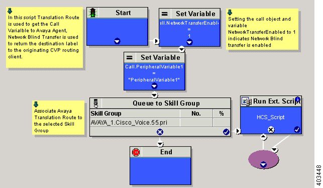
Translation Route for Avaya
A translation route is a temporary destination for a call that allows call information to be delivered with the call. Network Blind Transfer is used to return the destination label to the originating CVP routing client.
Configure Unified CCE
Enable Network Transfer Preferred
Perform the below steps for Avaya, CVP and CUCM PIMs:
Create Service
| Step 1 | Log in to Unified CCDM portal as a tenant or sub customer. |
| Step 2 | Select Resource Manager. |
| Step 3 | Select the folder from the left hand side panel that you want to create service. |
| Step 4 | Select Service from Resource drop-down list. |
| Step 5 | Enter Name. |
| Step 6 | Select appropriate Avaya peripheral from Peripheral drop-down list. |
| Step 7 | Select Advanced tab, choose Cisco_Voice from Media Routing Domain drop-down list. |
| Step 8 | Click Save. |
Configure Translation Route
| Step 1 | In Unified CCE Admin Workstation Server, navigate to Displays Configuration Manager window. |
| Step 2 | Expand . |
| Step 3 | In Translation Route tab: |
| Step 4 | Click Add Route. |
| Step 5 | In Route tab: |
| Step 6 | Click Add Peripheral Target |
| Step 7 | In
Peripheral Target tab:
|
| Step 8 | Click Add Label. |
| Step 9 | In
Label tab:
|
| Step 10 | Click Save. |
Configure Script
Following illustration explains to configure scripts.
Cisco Virtualized Voice Browser
- Create Golden Template for Cisco Virtualized Voice Browser
- Configure Unified CVP
- Configure Cisco Virtualized Voice Browser
Create Golden Template for Cisco Virtualized Voice Browser
Follow this sequence of tasks to create the golden template for Voice Browser. After each task, return to this page to mark the task "done" and continue the sequence:
| Sequence | Done? | Tasks | Notes |
| 1 |
Download VB_11.0_vmv8_v2.5.ova |
||
| 2 |
Create the virtual machine for Cisco Virtualized Voice Browser. |
Follow the procedure that is documented in, Create Virtual Machines. |
|
| 3 |
Install Cisco Virtualized Voice Browser. |
Follow the procedure for installing VOS applications for golden templates. See Install Unified Communications Voice OS based Applications. |
|
| 4 |
Convert the virtual machine to a Golden Template. |
Follow the procedure Convert the Virtual Machine to a Golden Template. |
After you create all golden templates, you can run the automation process (Automated Cloning and OS Customization). After you run the automation process, configure Cisco Virtualized Voice Browser. See Configure Cisco Virtualized Voice Browser.
Configure Unified CVP
Add Cisco Virtualized Voice Browser
| Step 1 | Login CVP operation console. |
| Step 2 | Navigate to . |
| Step 3 | Enter IP Address and Hostname of unified Voice Browser. |
| Step 4 | Keep the default trunk option in Group ID field. |
| Step 5 | Enter Username and Password. |
| Step 6 | Enter Enable Password. |
| Step 7 | Keep default option in Port field. |
| Step 8 | Click Sign in. |
| Step 9 | Click Save. |
Associate Dialed Number Pattern
Configure Cisco Virtualized Voice Browser
- Access Virtualized VB Administration Web Interface
- Access Virtualized VB Serviceability Web Page
- Add a SIP Trigger
- Configure Agent Greeting
- Configure Whisper Announcement
- Configure ASR and TTS
- Configure Courtesy Callback for Cisco VVB
Access Virtualized VB Administration Web Interface
The web pages of the Virtualized VB Administration web interface allow you to configure and manage the Virtualized VB system and its subsystems.
Use the following procedure to navigate to the server and log in to Vitualized VB Administration web interface.
| Step 1 | Open the Cisco
Virtualized Voice Browser Administration Authentication page from a web browser
and enter the following case-sensitive URL:https://<servername>/appadmin
In this example, replace <servername> with the hostname or IP address of the required Virtualized VB server. Displays Security Alert dialog box. | ||
| Step 2 | Login
Cisco
Virtualized VB Administration using your credentials.
| ||
| Step 3 | Import the license file and click Next to configure. DisplaysComponent Activation page. | ||
| Step 4 | After all the components status shows Activated, click Next. DisplaysSystem Parameters Configuration page. | ||
| Step 5 | Choose codec from the drop-down list and click Next. Displays Language Confirmation page. | ||
| Step 6 | Choose Language from the drop down list and appropriate options. | ||
| Step 7 | Click Next. |
Access Virtualized VB Serviceability Web Page
The Vitrualized VB Serviceability is used to view alarm and trace definitions for Virtualized VB services; start and stop the Virtualized VB Engine; monitor Virtualized VB Engine activity and to activate and deactivate services. After you log in to Cisco Virtualized VB Administration web page, you can access Virtualized VB Serviceability:
Add a SIP Trigger
Follow the below steps to add a SIP trigger:
| Step 1 | Log in to Cisco Virtualized Voice Browser Administration page. |
| Step 2 | Select . |
| Step 3 | Click Add New. |
| Step 4 | In Directory Information tab, enter Directory Number. |
| Step 5 | Select Language from the drop-down list. |
| Step 6 | Select Application Name from the drop-down list. |
| Step 7 | Optional, click Show More to associate the trigger for ASR. |
| Step 8 | In Override Media Termination field, select Yes option. |
| Step 9 | Move required dialog groups between Select Dialog Groups and Available Dialog Groups. |
| Step 10 | Click Add or Update to save the changes. |
Configure Agent Greeting
Configure Whisper Announcement
What to Do Next
Configure ASR and TTS
Configure ASR Subsystem
ASR subsystem allows user to choose options through IVR:
| Step 1 | Log in to Cisco Virtualized Voice Browser Administration page. |
| Step 2 | Select |
| Step 3 | Click Add New. |
| Step 4 | In Server Name field, enter hostname or IP address. |
| Step 5 | Enter Port Number. |
| Step 6 | Select Locales from the drop-down list and click Add Language. |
| Step 7 | Check Enabled Languages check-box. |
| Step 8 | Click Add. |
Configure TTS Subsystem
TTS subsystem converts plain-text (UNICODE) into IVR.
| Step 1 | Log in to Cisco Virtualized Voice Browser Administration page. | ||
| Step 2 | Select | ||
| Step 3 | Click Add New. | ||
| Step 4 | In Server Name field, enter hostname or IP address. | ||
| Step 5 | Enter Port Number. | ||
| Step 6 | Select Locales from the drop-down list and click Add Language. | ||
| Step 7 | Check Enabled Languages check-box. | ||
| Step 8 | Select
Gender from the below options:
| ||
| Step 9 | Click
Add.
|
Configure Courtesy Callback for Cisco VVB
What to Do Next
Configure courtesy callback for gateway, Unified CVP and Unified CCE, see Configure Courtesy Callback
 Feedback