- Preface
- Cisco HCS for Contact Center
- Prerequisites
- Design Consideration
- Shared Management and Aggregation
- Golden Template Process
- Create Golden Template
- Configure Customer Instance for Network Infrastructure
- Clone and OS Customization
- Configure Customer Instance
- Integration of Customer Instance with Shared Management
- Administration
- Configure Core Component Integrated Options
- Install and Configure Optional Cisco Components
- Remote Deployment Options
- Solution Serviceability
- Appendix
- Index
- Create a Customer Instance for the 500 Agents Deployment Model
- Upgrade VMware Tools
- Set Up Virtual Machine Startup and Shutdown
- Create a Domain Controller Server
- Configure Cisco Unified CCE Call Server
- Configure Unified CCE Data Server
- Enable Unified CVP Operations Console
- Configure Unified CVP Call Server Component
- Configure Unified CVP VXML Server Component
- Configure Unified CVP Reporting Server
- Configure Unified CVP Media Server
- Install Unified CVP licenses
- Configure Gateways
- Transfer Scripts and Media Files
- Configure SNMP
- Add Unified CCE Devices
- Add Unified Communications Manager Devices
- Add Unified Intelligence Center Devices
- Configure SIP Server Group
- Configure Dialed Number Patterns
- Configure Unified Intelligence Center Publisher
- Configure Unified Intelligence Center Subscriber
- Configure Unified Intelligence Center Reporting
- Configure Unified Intelligence Center Administration
- Unified Intelligence Center License and Sign-In
- Configure Live Data AW-Access
- Configure Live Data Machine Services
- Configure Live Data Unified Intelligence Data Sources
- Configure Live Data Reporting Interval
- Import Live Data Reports
- Add Certificate for HTTPS Gadget
- Configure Unified CCE Rogger for Small Contact Center Agent Deployment
- Configure Unified CCE Agent PG for Small Contact Center Agent Deployment
Configure Customer Instance
Create a Customer Instance for the 500 Agents Deployment Model
Follow this sequence of tasks to create a customer instance to deploy 500-agents for Cisco Hosted Collaboration Solution for Contact Center.
| Sequence | Task | Done? |
|---|---|---|
| 1 |
|
|
| 2 |
|
|
| 3 |
|
|
| 4 |
|
|
| 5 |
|
|
| 6 |
|
|
| 7 |
|
|
| 8 |
|
|
| 9 |
|
|
| 10 |
|
Upgrade VMware Tools
Set Up Virtual Machine Startup and Shutdown
Create a Domain Controller Server
- Create a Virtual Machine for the Domain Controller
- Install Microsoft Windows Server
- Install the Antivirus Software
- Configure a DNS Server
- Set Up the Domain Controller
- Create Two-Way Forest Trust
Create a Virtual Machine for the Domain Controller
| Step 1 | See, Set Up Virtual Machine Startup and Shutdown and create a new virtual machine from vCenter. |
| Step 2 | On the Name and Location page, provide a name for the Domain Controller. |
| Step 3 | In the Disk format field, choose the Thick Provisioned format. |
| Step 4 | Enter the virtual machine specifications as specified in Table 1. |
Install Microsoft Windows Server
To install Microsoft Windows Server 2012 R2 Standard Edition, see Install Microsoft Windows Server 2012 R2 Standard Edition.
Install the Antivirus Software
For third-party applications installation, see Install Antivirus Software.
Configure a DNS Server
To configuring a DNS server, see Configure DNS Server.
Set Up the Domain Controller
Complete the following procedure to set up the domain controller.
Create Two-Way Forest Trust
To create two-way forest trust between Unified CCE and CCDM, see Establish Two-Way Forest Trust.
Configure Cisco Unified CCE Call Server
This table lists the configuration procedures that you must perform for sides A and B of Unified CCE Call Server.
| Sequence | Task | Done? |
|---|---|---|
| 1 |
|
|
| 2 |
|
|
| 3 |
|
|
| 4 |
|
|
| 5 |
|
|
| 6 |
|
|
| 7 |
|
|
| 8 |
|
|
| 9 |
|
|
| 10 |
|
|
| 11 |
|
|
| 12 |
- Configure the Domain Manager
- Configure a Generic Peripheral Gateway
- Configure CTI Server
- Configure Media Routing Peripheral Gateway
- Configure CTI OS Server
- Install JTAPI
- Set Local Administrator Password
- Verify the Machine in Domain
- Cisco SNMP Setup
Configure the Domain Manager
Configure a Generic Peripheral Gateway
In CCE, the Generic Peripheral Gateway is called the Agent Peripheral Gateway.
Add a Generic PG
Add PIM1(Unified Communications Manager PIM)
To add Peripheral Interface Manager (PIM1) as the Unified Communication Manager PIM, do the following:
Add PIM2 (First VRU PIM)
To add the PIM2 as the first Voice Response Unit (VRU) PIM, do the following:
| Step 1 | In the Peripheral Interface Manager section of the Peripheral Gateway Component Properties dialog box, click Add. |
| Step 2 | Select the Client Type of VRU and PIM2, then click OK. |
| Step 3 | Check Enabled. |
| Step 4 | In the Peripheral Name field, enter CVP1. |
| Step 5 | In the Peripheral ID field, enter 5001. |
| Step 6 | In the VRU Hostname field, enter the hostname of CVP1 (Side A). |
| Step 7 | In the VRU Connect Port field, enter 5000. |
| Step 8 | In the Reconnect interval (sec) field, enter 10. |
| Step 9 | In the Heartbeat interval (sec) field, enter 5. |
| Step 10 | In the DSCP field and choose CS3(24). |
| Step 11 | Click OK. |
Add PIM3 (Second VRU PIM)
| Step 1 | In the Peripheral Interface Manager pane of the Peripheral Gateway Component Properties dialog box, click Add. |
| Step 2 | Select Client Type of VRU and PIM3. Then click OK. |
| Step 3 | Check Enabled. |
| Step 4 | In the Peripheral name field, enter CVP2. |
| Step 5 | In the Peripheral ID field, enter 5002. |
| Step 6 | In the VRU hostname field, enter the hostname of CVP1 (Side B). |
| Step 7 | In the VRU Connect port field, enter 5000. |
| Step 8 | In the Reconnect interval (sec) field, enter 10. |
| Step 9 | In the Heartbeat interval (sec) field, enter 5. |
| Step 10 | In the DSCP field, choose CS3(24). |
| Step 11 | Click OK . |
Add PIM4 (Third VRU PIM)
| Step 1 | In the Peripheral Interface Manager pane of the Peripheral Gateway Component Properties dialog box, click Add. |
| Step 2 | Select Client Type of VRU and PIM4 then click OK. |
| Step 3 | Check Enabled. |
| Step 4 | In the Peripheral name field, enter CVP3. |
| Step 5 | In the Peripheral ID field, enter 5003. |
| Step 6 | In the VRU hostname field, enter the hostname of CVP2 (Side A). |
| Step 7 | In the VRU Connect port field, enter 5000. |
| Step 8 | In the Reconnect interval (sec) field, enter 10. |
| Step 9 | In the Heartbeat interval (sec) field, enter 5. |
| Step 10 | In the DSCP field, choose CS3(24). |
| Step 11 | Click OK . |
Add PIM5 (Fourth VRU PIM)
| Step 1 | In the Peripheral Interface Manager pane of the Peripheral Gateway Component Properties dialog box, click Add. |
| Step 2 | Select Client Type of VRU and PIM4 then click OK. |
| Step 3 | Check Enabled. |
| Step 4 | In the Peripheral name field, enter CVP4. |
| Step 5 | In the Peripheral ID field, enter 5004. |
| Step 6 | In the VRU hostname field, enter the hostname of CVP2 (Side B). |
| Step 7 | In the VRU Connect port field, enter 5000. |
| Step 8 | In the Reconnect interval (sec) field, enter 10. |
| Step 9 | In the Heartbeat interval (sec) field, enter 5. |
| Step 10 | In the DSCP field, choose CS3(24). |
| Step 11 | Click OK . |
After Creating PIMs
Perform this task at the Peripheral Gateway Component Properties page.
| Step 1 | Enter 5000 in the Logical Controller ID field. | ||
| Step 2 | Enter 0 in the CTI Call Wrapup Data delay field. | ||
| Step 3 | In the VRU Reporting pane, click Service Control and check Queue Reporting. Click Next to open the Device Management Protocol Properties dialog box. | ||
| Step 4 | In the
Device Management Protocols Properties dialog box, complete all interface
fields:
| ||
| Step 5 | In the
Peripheral Gateway Network Interfaces dialog box, complete all interface
fields:
| ||
| Step 6 | In the Check Setup Information dialog box, click Next. | ||
| Step 7 | In the Setup Complete dialog box, click Finish. | ||
| Step 8 | Click
Exit
Wizard.
|
Configure CTI Server
| Step 1 | In the Instance Components pane of the Components Setup dialog box, click Add. | ||
| Step 2 | In the Component Selection dialog box, click CTI Server. | ||
| Step 3 | In the Server Component Properties dialog box, configure as follows: | ||
| Step 4 | Click Next. | ||
| Step 5 | In the Network Interface Properties dialog box, fill in all interface fields Then click Next . | ||
| Step 6 | Enter the PG public interfaces, CG private interface, and CG visible interfaces details and click Next. | ||
| Step 7 | Under the Check Setup Information page, click Next. | ||
| Step 8 | In the Setup Completed dialog box, click Finish. | ||
| Step 9 | Click
Exit
Setup.
|
Configure Media Routing Peripheral Gateway
Complete the following procedure to set up the Unified CCE Media Routing Peripheral Gateway. The MR PG is required; you must configure it.
The Media Routing Peripheral Gateway can optionally have two PIMs—the MultiChannel PIM (PIM1) and the Outbound PIM (PIM2). The Multichannel PIM can be configured for Unified WIM and Unified EIM. You can configure these PIMs if you use those features.
Add Media Routing PG
Complete the following procedure to add the MR PG and the Multichannel PIM (PIM1) and the Outbound PIM (PIM2). You can have one of each PIM. The Multichannel PIM can be used for either Unified WIM and Unified EIM
| Step 1 | Choose . | ||
| Step 2 | Click Add in the Instance Components pane, and from the Component Selection dialog box choose Peripheral Gateway. | ||
| Step 3 | In the Peripheral Gateway Properties dialog box: | ||
| Step 4 | In the
Peripheral Interface Manager
pane of the Peripheral Gateway Component Properties dialog box, click
Add
and configure PIM1 (the Multichannel PIM) with the
Client Type of Media Routing.
| ||
| Step 5 | Click
Add and
configure PIM2 (the Outbound PIM) with the client type of Media Routing as
follows:
| ||
| Step 6 | Enter 5001 in the Logical Controller ID field. | ||
| Step 7 | Enter 0 in the CTI Call Wrapup Data delay field. Click Next. | ||
| Step 8 | In the
Device Management Protocol Properties dialog box, configure as follows:
| ||
| Step 9 | In the
Peripheral Gateway Network Interfaces dialog box, enter the Private Interfaces
and the Visible Interfaces.
This step applies only to Side A.
| ||
| Step 10 | In the Check Setup Information dialog box, click Next. | ||
| Step 11 | In the Setup Complete dialog box, click Finish. | ||
| Step 12 | Click
Exit
Setup.
|
Configure CTI OS Server
| Step 1 | Mount the CTI OS ISO image or copy the CTI OS installer to the local drive of the Unified CCE machine with an Agent PG.. | ||
| Step 2 | If a maintenance release for CTI OS is available, copy the maintenance release to the local drive . | ||
| Step 3 | Navigate to %Home\CTIOS\Installs\CTIOS Server and run setup.exe. Click Yes to the warning that the SNMP service will be stopped and then restarted after the installation completes. | ||
| Step 4 | Accept the Software License Agreement. | ||
| Step 5 | Browse to the location for the latest Maintenance Release, if any. Click Next. | ||
| Step 6 | In CTI OS
Instance dialog box, click in the CTI OS Instance List pane. In the Add CTI OS
Server Instance window, enter your instance name and click
OK.
| ||
| Step 7 | Click Add in the CTI OS Server List pane and click OK. | ||
| Step 8 | In the Enter Desktop Drive dialog box, choose drive C and click OK. | ||
| Step 9 | In the CTI Server Information dialog box, enter the IP address of the Unified CCE machines where CTI Server is installed, and enter the ports for Side A (42027) and Side B (43027). Click Next. | ||
| Step 10 | In the Peripheral Identifier dialog box, enter the following values and Click Next . | ||
| Step 11 | In the Connect Information dialog box, enter Listen Port 42028 and accept all defaults and then click Next. | ||
| Step 12 | In the Statistics Information dialog box, check Polling for Agent Statistics at End Call and then click Next. | ||
| Step 13 | In the IPCC Silent Monitor Type dialog box, set Silent Monitor Type to CCM Based and click Next. | ||
| Step 14 | In the Peer CTI OS Server dialog box, configure as follows: | ||
| Step 15 | Click Finish. | ||
| Step 16 | In the Cisco CTI OS Server Security dialog box, uncheck Enable Security. Click OK. | ||
| Step 17 | In the CTI OS Security dialog box, click Finish. | ||
| Step 18 | When prompted to restart the computer, click Yes. If there is a Maintenance Release, its installation begins automatically. | ||
| Step 19 | Follow all prompts to install the Maintenance Release, if there is one. | ||
| Step 20 | When the Maintenance Release install completes, click Finish and follow the prompts to restart. | ||
| Step 21 | Access Registry Editor (Run > regedit). | ||
| Step 22 | Navigate to HKEY_LOCAL_MACHINE\SOFTWARE\Cisco Systems,Inc.\Ctios\CTIOS_<instance name>\CTIOS1\Server\Agent. | ||
| Step 23 | Set forceLogoutOnSessionClose to 1. |
Install JTAPI
 Note | This procedure is required for the Unified Contact Center Enterprise Machine having a PG with Unified Communications Manager PIM. However, you must postpone this task until after you Configure Unified Communications Manager. |
Complete the following procedure to install JTAPI on the Unified Contact Center Enterprise Machine having a PG with Unified Communications Manager PIM for Side A and Side B.
| Step 1 | Launch the Unified Communications Manager in a browser (https://{callmanager-hostname}) and log in. |
| Step 2 | Navigate to . Click Find. |
| Step 3 | Download the Cisco JTAPI 32-bit Client for Windows. |
| Step 4 | Install the downloaded file, accepting all of the default settings. |
| Step 5 | At the prompt, enter the IP address for the Unified Communications Manager TFTP Server, and click Next. |
| Step 6 | Click Finish. |
Set Local Administrator Password
Verify the Machine in Domain
For Unified CCE golden template, the Automation Tool script clones and deploys the virtual machines automatically to the destination domain. Complete the following procedure to verify if the Virtual Machine is placed in destination domain.
For small contact center deployment model Agent PG can be in customer domain instead of service provider domain.
| Step 1 | Log in to the Unified CCE machine. |
| Step 2 | Navigate to Start > All Programs > Administrative Tools > Server Manager to verify if the Virtual Machine is mapped to correct domain. If the machine is not in Domain, follow the below steps. |
| Step 3 | Click Change System Properties on Right side panel to open System Properties. |
| Step 4 | In Computer name tab, Click Change. |
| Step 5 | Choose Domain radio button to change the member from Workgroup to Domain. |
| Step 6 | Enter fully qualified Domain name and Click OK. |
| Step 7 | In Windows security pop-up, Validate the domain credentials and click OK. |
| Step 8 | On successful authentication, Click OK. |
| Step 9 | Reboot the server and login with domain credentials. |
Cisco SNMP Setup
Complete the following procedures to configure Cisco SNMP:
- Add Cisco SNMP Agent Management Snap-In
- Save Cisco SNMP Agent Management Snap-In View
- Set Up Community Names for SNMP V1 and V2c
- Set Up SNMP User Names for SNMP V3
- Set Up SNMP Trap Destinations
- Set Up SNMP Syslog Destinations
Add Cisco SNMP Agent Management Snap-In
You can configure Cisco SNMP Agent Management settings using a Windows Management Console snap-in.
Complete the following procedure to add the snap-in and change Cisco SNMP Management settings.
| Step 1 | From the Start menu, enter mmc.exe /32. |
| Step 2 | From the Console, choose. |
| Step 3 | In the Add or Remove Snap-ins dialog box, choose Cisco SNMP Agent Management from the list of available snap-ins. Click Add. |
| Step 4 | In the Selected snap-ins pane, double-click Cisco SNMP Agent Management. |
| Step 5 | In the Extentions for Cisco SNMP Agent Management dialog box, select Always enable all available extentions. Click OK. |
| Step 6 | In the Add/Remove Snap-in window, click OK. The Cisco SNMP Agent Management Snap-in is now loaded into the console. |
Save Cisco SNMP Agent Management Snap-In View
After you load the Cisco SNMP Agent Management MMC snap-in, you can save the console view to a file with a .MSC file extension. You can launch the file directly from Administrative Tools.
Complete the following procedure to save the Cisco SNMP Agent Management snap-in view.
Set Up Community Names for SNMP V1 and V2c
If you use SNMP v1 or v2c you must configure a community name so that Network Management Systems (NMSs) can access the data your server provides. Use SNMP community names to authenticate data exchange of SNMP information. An NMS can exchange SNMP information only with servers that use the same community name.
Complete the following procedure to configure the community name for SNMP v1 and v2c.
Ensure Cisco SNMP is added and saved using the procedures Add Cisco SNMP Agent Management Snap-In and Save Cisco SNMP Agent Management Snap-In View.
| Step 1 | Choose . |
| Step 2 | Right-click Cisco SNMP Agent Management and choose Run as administrator. |
| Step 3 | The Cisco SNMP Agent Management screen lists some of the configurations that require SNMP for traps and system logs. |
| Step 4 | Right-click Community Names (SNMP v1/v2c) and choose Properties. |
| Step 5 | In the Community Names (SNMP v1/v2c) Properties dialog box, click Add New Community. |
| Step 6 | In the Community Name field, enter a community name. |
| Step 7 | In the Host Address List, enter the host IP address. |
| Step 8 | Click Apply and click OK. |
Set Up SNMP User Names for SNMP V3
If you use SNMP v3 you must configure a user name so that NMSs can access the data your server provides.
Complete the following procedure to configure a user name for SNMP v3.
Ensure Cisco SNMP is added and saved using the procedures Add Cisco SNMP Agent Management Snap-In and Save Cisco SNMP Agent Management Snap-In View.
Set Up SNMP Trap Destinations
You can configure SNMP Trap Destinations for SNMP v1, SNMP v2c, and SNMP v3. A Trap is a notification that the SNMP agent uses to inform the NMS of a certain event.
Complete the following procedure to configure the trap destinations.
Ensure Cisco SNMP is added and saved using the procedures Add Cisco SNMP Agent Management Snap-In and Save Cisco SNMP Agent Management Snap-In View.
| Step 1 | From the Console Root, choose . |
| Step 2 | Click Add Trap Entity. |
| Step 3 | Click the SNMP version that your NMS uses. |
| Step 4 | In the Trap Entity Name field, enter a name for the trap entity. |
| Step 5 | Choose the User Name/Community Name that you want to associate with this trap. This list is auto-populated with existing configured users/community names. |
| Step 6 | Enter one or more IP addresses in the IP Address entry field. Click Insert to define the destinations for the traps. |
| Step 7 | Click Apply and click
Save to save the new trap destination.
The trap entity name appears in the Trap Entities section at the top of the dialog box. |
| Step 8 | Click OK. |
Set Up SNMP Syslog Destinations
You can configure Syslog destinations for SNMP from the Cisco SNMP Agent Management Snap-in.
Complete the following procedure to configure Syslog destinations.
Configure Unified CCE Data Server
This section explains the configuration procedures you must perform for the Unified CCE Data Servers.
| Sequence | Task | Done? |
|---|---|---|
| 1 | ||
| 2 | ||
| 3 | ||
| 4 | ||
| 5 | ||
| 6 | ||
| 7 |
Configure Administration Server and Real-Time Data Server Components |
|
| 8 | ||
| 9 | ||
| 10 | ||
| 11 |
- Configure Network Cards
- Configure Unified CCE Encryption Utility
- Configure SQL Server
- Configure Secondary Drive
- Configure the Unified CCE Logger
- Configure Administration Server and Real-Time Data Server Components
- Load Base Configuration
- Verify Cisco Diagnostic Framework Portico
- Final Tasks
Configure Network Cards
Note | Do this for all the Unified Contact Center Enterprise virtual machines that have two network adapters. |
| Step 1 | Navigate to Start > Control Panel > Network and Internet > Network and Sharing Center. |
| Step 2 | Click Change adapter settings to open the Network Connections page. |
| Step 3 | Rename the network adapter with Visible IP address configurations as Visible. |
| Step 4 | Rename the network adapter with Private IP address configurations as Private. |
| Step 5 | On the Network Connections page, press Alt N to display the Advanced menu. |
| Step 6 | From the Advanced menu, select Advanced Settings. |
| Step 7 | Under Adapters and Bindings, sort the connections so that visible is on top. |
| Step 8 | Click OK. |
Configure Private Ethernet Card
| Step 1 | Right-click private and select Properties. |
| Step 2 | Uncheck Client for Microsoft Networks. |
| Step 3 | Uncheck File and Printer Sharing for Microsoft Networks. |
| Step 4 | Uncheck Internet Protocol Version 6 (TCP/IPV6). |
| Step 5 | Check Internet Protocol Version 4 (TCP/IPV4) and click Properties. |
| Step 6 | Click the Advanced button. Open the DNS tab. Uncheck Register this connection's addresses in DNS. |
| Step 7 | Add an entry for the private IP address. Append a suffix such as p to the hostname for this IP, to identify it as private. |
| Step 8 | Optional: Add another entry for the public high IP address. Append a suffix such as ph to the hostname for this IP, to identify it as public high. |
| Step 9 | Click OK twice. Then, click Close. |
Configure Visible Ethernet Card
| Step 1 | Right-click Visible and select Properties. |
| Step 2 | Check Client for Microsoft Networks. |
| Step 3 | Check File and Printer Sharing for Microsoft Networks. |
| Step 4 | Uncheck Internet Protocol Version 6 (TCP/IPV6). |
| Step 5 | Check Internet Protocol Version 4 (TCP/IPV4) and click Properties. |
| Step 6 | Confirm the Public IP address, Subnet mask, Default gateway and Preferred DNs server, and click Advanced. |
| Step 7 | On the Advanced tab, enter the high public addresses. |
| Step 8 | On the DNS tab, in the DNS suffix for this connection field, enter the name of the local DNS zone for the server and check Register this connection's addresses in DNS. |
| Step 9 | Optional: Add another entry for the public high IP address. Assign an unique suffix, for example, ph to the hostname for this IP, to identify it as public high. |
| Step 10 | If the server requires access to resources in a different trusting or trusted domain or DNS zone, select Append these DNS suffixes (in order) and enter the local DNS zone for the server first, and then add the other secondary zones that represent the trusting or trusted domain. |
| Step 11 | Click OK twice. Then, click Close. |
Configure Unified CCE Encryption Utility
What to Do Next
Create and Bind System CLI Certificate
Complete the following procedure to create and bind the system CLI certificate:
Configure SQL Server
Configure Secondary Drive
DO THIS FOR Virtual Machines that require an additional hard drive to archive data.
| Step 1 | Open Computer Management. |
| Step 2 | Expand Storage in the left pane, click Disk Management. |
| Step 3 | Right-click Disk 1 and choose Online. |
| Step 4 | Right-click Disk 1 and choose Initialize Disk. |
| Step 5 | In Initialize Disk pop up window, under Select disks. Check Disk 1 and choose MBR (Master Boot Record) under Use the following partition style for the selected disks pane. Click OK. |
| Step 6 | Create a new disk partition as follows: right-click the disk you just initialized, choose New Simple Volume, and run the wizard. |
Configure the Unified CCE Logger
Complete the following procedure to configure the Unified CCE Logger.
Note | Ensure that your browser is enabled. |
| Step 1 | Launch the Unified CCE Web Setup. | ||
| Step 2 | Sign in using as domain user having local Administrator rights. | ||
| Step 3 | Click Instance Management, and then click Add. | ||
| Step 4 | In the Add Instance window, select Facility and Instance from the drop-down list. | ||
| Step 5 | In the Instance Number field, enter 0. Click Save. | ||
| Step 6 | Configure the
logger database as follows:
| ||
| Step 7 | In the Create Database window, configure the following to create the Log: | ||
| Step 8 | In the Add Device dialog box, configure as follows: | ||
| Step 9 | In the Create Database dialog box, click Add. | ||
| Step 10 | In the Add Device dialog box, configure as follows: | ||
| Step 11 | In the Create
Database dialog box, click
Create and
click
Start.
When you see the successful creation message, click OK and click Close. | ||
| Step 12 | Configure the
logger component as follows:
| ||
| Step 13 | On the Additional Options page, configure the following and click Next: | ||
| Step 14 | On the Data
Retention page, modify the Database Retention Configuration table:
| ||
| Step 15 | On the Data Purge page, configure purge for a time when there is low demand on the system. Click Next. | ||
| Step 16 | Review the
Summary page, and then click
Finish.
|
Database and Log File Size
Complete the following procedure to increase the database and log sizes.
Use DB Estimator Tool to calculate database and log file size.
Alternative option is to size the database and log using the values from Table 1. The values in the table for HCS 500 and 1000 agent deployments are sized without considering optional HDS.| Step 1 | Open SQL Server 2014 Management Studio. | ||||||||||||||||
| Step 2 | Click Connect. In the left pane, expand Databases. | ||||||||||||||||
| Step 3 | Right-click Logger database [<Instance>_<Side>] and select Properties.. | ||||||||||||||||
| Step 4 | In the left pane, select Files. Ensure that Auto Growth is disabled for data and log files. | ||||||||||||||||
| Step 5 | Set the
initial size of the data and log files according to
DB Estimator Tool or
from the following table:
|
Configure Administration Server and Real-Time Data Server Components
| Step 1 | Go to the Unified CCE Web Setup. | ||
| Step 2 | Choose . Click Add. | ||
| Step 3 | On the Add Administration & Data Servers page, configure as follows: | ||
| Step 4 | On the Role page, choose the option Administration Server and Real-time Data Server (AW). Click Next. | ||
| Step 5 | Configure
primary/secondary Administration and Data Servers connectivity, as follows:
Follow the below steps for primary:
Follow the below steps for secondary: | ||
| Step 6 | On the Database
and Options page, configure as follows:
| ||
| Step 7 | On the Central
Controller Connectivity page, configure as follows:
| ||
| Step 8 | Review the
Summary page, and then click
Finish.
|
Load Base Configuration
| Step 1 | Download the HCS-11.0.1-500-and-1000-Agent-Day1-Configuration.zip file . Save it locally and unzip it. |
| Step 2 | Download the Domain_Update_Tool.zip file. Save it locally and unzip it. |
| Step 3 | Copy the configuration folder to the local drive of CCE Data Server on Side A. |
| Step 4 | Open the ICMDBA Tool on the CCE Data Server on Side A. |
| Step 5 | Select the CCE Data Server and expand the tree to <instance name>_sideA. |
| Step 6 | Select Data on the menu bar and click Import. |
| Step 7 | Browse to locate the configuration folder and click Open. |
| Step 8 | Click OK and then click Import. |
| Step 9 | Click Start and then click OK on all messages. |
| Step 10 | Navigate to the folder Domain_Update_Tool and right-click UpdateDomain.PS1. and Run with PowerShell. Respond as follows: |
| Step 11 | Return to the ICMDBA tool. Open Data on the menu bar and click Synchronize. |
| Step 12 | Click Start and then click OK on all messages. |
Verify Cisco Diagnostic Framework Portico
Do this for the Unified CCE machines.
| Step 1 | Open the command prompt and enter cd C:\. |
| Step 2 | Enter cd icm\serviceability\diagnostics\bin and press Enter. |
| Step 3 | Enter DiagFwCertMgr /task:CreateAndBindCert /port:7890 and press Enter. |
| Step 4 | Go to Start -> Run and enter services.msc to open the Services tool. Make sure the Cisco Diagnostic Framework service is running. If it is not running start it. |
| Step 5 | Open Diagnostic Framework Portico: Start > Programs > Cisco Unified CCE Tools > Diagnostic Framework Portico. Then make sure you can log in to the Diagnostic Framework Portico using domain user credentials. |
Final Tasks
Set the HCS Deployment Type
Start Unified CCE Services
The Unified CCE components run as a Windows service on the host computer. You can start, stop, or cycle these services from the Unified CCE Service Control tool on the desktop.
Note | This procedure is required for activating Unified CCE services. However, you must postpone this task until you install Unified CCE components in all Virtual machines given in the deployment model. |
Configure Unified CVP
| Sequence | Task | Done? |
|---|---|---|
|
1 |
||
|
2 |
||
|
3 |
- Configure Unified CVP Server
- Configure Unified CVP Reporting Server
- Configure Cisco Unified CVP Operations Console
Configure Unified CVP Server
This section explains the procedures to configure Unified CVP Server.
| Sequence | Task | Done? |
|---|---|---|
|
1 |
||
|
2 |
||
|
3 |
Validate Network Card
| Step 1 | Select Start and right-click Network. |
| Step 2 | Select Properties. Then select Change Adapter Settings. |
| Step 3 | Right-click Local Area Connection and select Properties. |
| Step 4 | Uncheck Internet Protocol Version 6 (TCP/IPV6). |
| Step 5 | Check Internet Protocol Version 4 and select Properties. |
| Step 6 | Confirm the data for Visible IP addresses, Subnet mask, Default gateway and Preferred and alternate DNS servers. |
| Step 7 | Click OK. |
Setup Unified CVP Media Server IIS
| Step 1 | Navigate to . |
| Step 2 | Choose Server Manager option navigate to . |
| Step 3 | Goto Installation Type tab, choose Role based or featue based installation option and click Next. |
| Step 4 | On Server Selection window, select server from the list and click Next. |
| Step 5 | Check Web Sever(IIS) check box to enable IIS and click Next. |
| Step 6 | No additional features are necessary to install Web Adaptor, click Next. Displays Web Server Role(IIS) tab. |
| Step 7 | Click Next. Displays Select Role Services tab. |
| Step 8 | Ensure that the web server components listed below are enabled. |
| Step 9 | Click Next. |
| Step 10 | Ensure that your settings are correct and click Install. |
| Step 11 | After installation click Close. |
Setup FTP Server
Install FTP Server
| Step 1 | Goto . |
| Step 2 | Choose Server Manager and click Manage. |
| Step 3 | Choose Add Roles and Features and click Next. |
| Step 4 | Goto Installation Type tab, choose Role-based or feature-based Installation and click Next. |
| Step 5 | Choose required server from the list and click Next. |
| Step 6 | No additional features are necessary to install the web Adaptor and click Next. |
| Step 7 | In Web Server Role(IIS) window click Next. |
| Step 8 | Check FTP Server check box and click Next. |
| Step 9 | Click Install. |
Enable FTP Server
| Step 1 | Goto . |
| Step 2 | Choose Sever Manager and click IIS. |
| Step 3 | Right-click on the server that you want to enable FTP server and choose Internet Information Services (IIS) Manager option from submenu. |
| Step 4 | Goto Connections panel: |
| Step 5 | Enter FTP Site Name. |
| Step 6 | Browse C:\Inetpub\wwwroot in Physical Path field and click Next. |
| Step 7 | Choose IP Address of CVP from the drop-down list. |
| Step 8 | Enter Port number. |
| Step 9 | Check No SSL check box and click Next. |
| Step 10 | Check Anonymus and Basic check boxes in Authentication panel. |
| Step 11 | Choose All Users from Allow Access To drop-down list. |
| Step 12 | Check Read and Write check boxes and click Finish. |
Configure Basic Settings for FTP Server
Configure Unified CVP Reporting Server
Note |
| Sequence | Task | Done? |
|---|---|---|
| 1 | Validate Network Card | |
| 2 | ||
| 3 | Install Unified CVP Reporting Server | |
| 4 | Unified CVP Reporting Users | |
| 5 | Create Data Source and Import Report Templates |
Unified CVP Reporting Users
Create Reporting Users
Unified CVP reporting users can sign in to Unified Intelligence Center only if they exist in the Administration console as Superusers or if Active Directory (AD) is configured in the Unified Intelligence Center Administration console for their domain:
-
Superusers who are added are considered to be IP Multimedia Subsystem (IMS) users.
-
Users who are authenticated through Active Directory are considered to be Lightweight Directory Access Protocol (LDAP) users.
Both IMS users and LDAP users can log in to Unified Intelligence Center reporting and are restricted to the limited Login User role until the Unified Intelligence Center reporting security administrator gives them additional roles and flags them as active users.
Although you can create a user on the Unified Intelligence Center User List page, an entry on the User List is not sufficient for that user to sign in to the Unified Intelligence Center. One reason to create users on the User List page is to expedite the permissions for users before their Active Directory domain is configured.
Create Superusers
| Step 1 | Log in to the Cisco Unified Intelligence Center Administration Console (http://{hostname}/oamp). |
| Step 2 | Navigate to Admin User Management > Admin User Management to open the Users page. |
| Step 3 | Click Add New to add and configure a new user or click an existing username to edit the configuration for that user. This page has three tabs: General, Credentials, and Policy. For information about completing these tabs, see at http://www.cisco.com/en/US/products/ps9755/prod_maintenance_guides_list.html or the Administration console online help. |
| Step 4 | Click Save. |
Configure Active Directory Server
Fields on the Active Directory tab configure the Active Directory server to authenticate reporting users as they log in to the Unified Intelligence Center Web application.
You must configure Active Directory for the Unified ICM/CC supervisors so that they can sign in as Unified Intelligence Center Reporting users.
Note | Cisco Unified Intelligence Center uses LDAP V2 which does not support all Unicode characters that are used in the first name or surname of LDAP users. |
Active Directory is not used to authenticate Administration Super Users. These Super Users can only be authenticated through the local database. The first Super User is added during installation. All other Super Users are added through the Admin User Management interface, and their credentials are encrypted into the local database.
To navigate to this page, choose and select the Active Directory tab.
|
Field |
Description |
||
|---|---|---|---|
|
Host Address and Port for Primary Active Directory Server |
Provide the Host name or IP address and the port of the Primary Active Directory server. The port defaults to 389. |
||
|
Host Name and Port for Redundant Active Directory Server |
Provide the Host name or IP address and the port of the Redundant Active Directory server. The port defaults to 389. |
||
|
Use SSL |
Check these boxes if you want the connection from the Unified device to the Active Directory connection to be encrypted with SSL while doing authentication. |
||
|
Manager Distinguished Name |
|
||
|
Manager Password |
Enter the Active Directory manager password. |
||
|
Confirm Manager Password |
Confirm the Active Directory manager password. |
||
|
User Search Base |
Specify the user search base. For example, on a default installation of Microsoft AD, CN=users, DC=MYSERVER, DC=COM, replace MYSERVER and COM with your respective hostname.
|
||
|
Attribute for User ID |
Whenever a user logs in, Unified Intelligence Center searches for that user in the LDAP (Lightweight Directory Access Protocol) using the login attribute specified in the LDAP configuration. After the user is found, the full DNS of the user is extracted and used for authenticating the user. The login attribute specified in the LDAP configuration will be the property against which LDAP search is issued to find the matching username. If you do not know which attribute to use, use sAMAccountName, which is the default Microsoft username attribute. Different organizations settle on different LDAP attributes to identify the user name across the organization, depending on the tools used to administer LDAP within their organizations. This attribute allows you to customize the login depending on the attribute used. Even a custom attribute can be specified using this dialog. sAMAccountName indicates the user attribute to search the user for is the userPrincipalName. sAMAccountName contains just the short user name. For example, jDoe for the user John Doe. userPrincipalName indicates the user attribute to search the user for is the userPrincipalName. This attribute contains user name in the email format, in the form user@compay.com. Therefore this entire string becomes the user name and not just user. Therefore when this attribute is selected this entire form of username has to be typed in as the username in the login box.
Contact your Active Directory Administrator for the correct attribute to use. |
||
|
UserName Identifiers |
Users are stored in Unified Intelligence Center in the format <UserName Identifier>\<username> The UserName Identifiers are used to identify the different kinds of users within Unified Intelligence Center. For example, local, LDAP, user-synced user, users from different LDAP domains and so on. The username identifier has to be first declared for use in this page before it can be used. When LDAP is configured at least one identifier must be configured and set as default so that LDAP users can be identified in the system. When userPrincipalName are used as the LDAP attribute for searching users in the domain, valid formats for username has to be supplied in the form of @company.com. Unlike sAMAccountName any identifier cannot be configured. Only existing identifiers as configured in the LDAP Active Directory userPrincipalName attribute should be configured here. Users are created as company\user. UserSychronization brings in users in format <syncdomain>\username and collections will have users in the same format. It is therefore required that these users login to Unified Intelligence Center using the syncdomain\user syntax. To enable please add syncdomain or @syncdomain.com (if you are using userPrincipalName) to the list of valid identifiers. The maximum allowed length of a UserName identifier is 128 characters. |
||
|
set Default. (UserName Identifier) |
Default identifiers allows users to login without typing the full domain identifier (<domain>\user) or the userPrincipalName suffixes to usernames (user <@company.com>) on the Login page. It can be set by choosing one of the Identifiers from the list box and by clicking the Set Default button. Users who need to use any other identifier can still login by typing their full identifier in the login box. For example, domain2\user or netbiosname\user, provided those identifiers have already been configured. |
||
|
Test Connection button |
Click to test the connection to the primary and secondary LDAP servers and display the connection status. |
- Save saves the configuration information you entered for the active directory. Clicking Save does not validate the configuration.
-
Refresh rolls back all changes since the last save and reloads the values set during the last save.
The UserName Identifier list box is pre-populated with the UserName Identifiers after upgrade to 9.0 release from 8.x releases based on the list of user names stored in the Unified Intelligence Center database. The most frequently occurring identifier in the list of user name is auto-selected as the default.
Note | You cannot save LDAP configuration unless you choose a default Identifier from the UserName Identifiers list box and clicking the Set Default button. |
Sign In to Cisco Unified Intelligence Center Reporting Interface
Perform the following procedure to sign in to the Unified Intelligence Center reporting interface.
| Step 1 | Sign in to the Cisco Unified Intelligence Center Administration Console (http://{hostname}/oamp). |
| Step 2 | Navigate to Control Center > Device Control. |
| Step 3 | Click on the name of the Member node you want to access. This opens the Cisco Unified Intelligence Center login page for that member. |
| Step 4 | Enter your user ID and password. The Overview page appears. |
What to Do Next
Create Data Source and Import Report Templates
| Sequence | Task | Done? |
|---|---|---|
| 1 | Create Data Source for Cisco Unified CVP Report Data | |
| 2 | Obtain Cisco Unified CVP Report Templates | |
| 3 | Import Unified CVP Report Templates and Set Data Source |
- Create Data Source for Cisco Unified CVP Report Data
- Obtain Cisco Unified CVP Report Templates
- Import Unified CVP Report Templates and Set Data Source
Create Data Source for Cisco Unified CVP Report Data
Similar to creating an Open Database Connectivity (ODBC) connection, this task is necessary to access the Unified CVP reporting data.
In Unified Intelligence Center, the user must perform this task with the System Configuration Administrator User Role.
Perform the following procedure to create a data source.
| Step 1 | Log in to the Unified Intelligence Center at https://<hostname of CUIC Publisher>:8444/cuic. | ||||||||||||||||||||||||||||||
| Step 2 | Select the Data Sources drawer to open the Data Sources page. | ||||||||||||||||||||||||||||||
| Step 3 | Click Create to open an Add Data Source window. | ||||||||||||||||||||||||||||||
| Step 4 | Complete fields
on this page as follows:
| ||||||||||||||||||||||||||||||
| Step 5 | Click
Test
Connection.
If the status is not Online, review the error message to determine the cause and edit the data source accordingly. | ||||||||||||||||||||||||||||||
| Step 6 | Click
Save to close the Add Data Source window.
The new data source appears on the Data Sources list. |
Obtain Cisco Unified CVP Report Templates
Who can obtain import Unified CVP report templates: any user in your organization.
The Unified CVP reporting template XML files are installed with Unified CVP. Locate them and copy them to a Cisco Unified Intelligence Center client workstation.
Perform the following procedure to obtain import Unified CVP report templates.
| Step 1 | In the Unified CVP server, locate the Unified CVP template files. These are XML files that reside on the reporting server in %CVP_HOME%\CVP_Reporting_Templates. You can also find them in the Installation directory \Downloads and Samples\Reporting Templates. |
| Step 2 | Choose the files and copy them to the client computer from where you can launch the Unified Intelligence Center Reporting web application. |
Import Unified CVP Report Templates and Set Data Source
Before reporting users can run the Unified CVP report templates in the Unified Intelligence Center reporting application, a Unified IC reporting user with permission to do so must import them into Unified IC and associate them with the Unified CVP Data Source.
| Step 1 | Launch the Unified Intelligence Center web application using the URL http://<HOST ADDRESS>:8444/cuic |
| Step 2 | Enter your User
Name and Password.
This opens the Overview page. |
| Step 3 | ClickReports. |
| Step 4 | Right-click the top Reports folder and select Create Sub-Category. |
| Step 5 | Name the new sub-category as a container for Unified CVP reports. Click OK. |
| Step 6 | Click Import Reports. |
| Step 7 | Browse to the location where you copied the Unified CVP Reporting templates files. |
| Step 8 | Select a
report.
This populates the File Name with the full path for the report. |
| Step 9 | Click Import. |
| Step 10 | From the Data source for Report Definition and Data source for value List drop down lists, Choose the Data source you created to access the Unified CVP Reporting database. |
| Step 11 | Save to the Unified CVP sub-category folder you created in Step 5. |
| Step 12 | Click Import. |
| Step 13 | Repeat for the callback templates. |
Configure Cisco Unified CVP Operations Console
| Sequence | Task | Done? |
|---|---|---|
| 1 | Validate Network Card | |
| 2 | Enable Unified CVP Operations Console | |
| 3 | Configure Unified CVP Call Server Component | |
| 4 | Configure Unified CVP VXML Server Component | |
| 5 | Configure Unified CVP Reporting Server | |
| 6 | Configure Unified CVP Media Server | |
| 7 | Install Unified CVP licenses | |
| 8 | Configure Gateways | |
| 9 | Add Unified CCE Devices | |
| 10 | Add Unified Communications Manager Devices | |
| 11 | Add Unified Intelligence Center Devices | |
| 12 | Transfer Scripts and Media Files | |
| 13 | Configure SNMP | |
| 14 | Configure SIP Server Group | |
| 15 | Configure Dialed Number Patterns |
- Enable Unified CVP Operations Console
- Configure Unified CVP Call Server Component
- Configure Unified CVP VXML Server Component
- Configure Unified CVP Reporting Server
- Configure Unified CVP Media Server
- Install Unified CVP licenses
- Configure Gateways
- Transfer Scripts and Media Files
- Configure SNMP
- Add Unified CCE Devices
- Add Unified Communications Manager Devices
- Add Unified Intelligence Center Devices
- Configure SIP Server Group
- Configure Dialed Number Patterns
Enable Unified CVP Operations Console
| Step 1 | Go to Start > Run and type services.msc. |
| Step 2 | Check that Cisco CVP OPSConsoleServer service is running. If it is not, right-click that service and click Start. |
| Step 3 | Go to Start > All Programs > Cisco Unified Customer Voice Portal > Operation Console to open the Unified CVP OPSConsole page. If you are using Microsoft Internet Explorer, you will need to accept the self-signed certificate. |
Configure Unified CVP Call Server Component
| Step 1 | On the Unified CVP OAMP server, go to . |
| Step 2 | Click Operations Console and log in. |
| Step 3 | Navigate to Device Management > Unified CVP Call Server. |
| Step 4 | Click Add New. |
| Step 5 | On the General tab, enter the IP address and the hostname of the Cisco Unified CVP Server. Check ICM, IVR, and SIP. Click Next. |
| Step 6 | Click the ICM tab. For each of the Cisco Unified CVP Call Servers, retain the default port of 5000 for the VRU Connection Port. |
| Step 7 | Click the SIP tab: |
| Step 8 | Click the Device Pool tab. Make sure the default device pool is selected. |
| Step 9 | (Optional) Click
the
Infrastructure tab. In the Configuration Syslog
Settings pane, configure these fields as follows:
|
| Step 10 | Click Save & Deploy. |
| Step 11 | Repeat this procedure for the remaining Unified CVP Call Servers. |
Configure Unified CVP VXML Server Component
Note |
|
| Step 1 | In the Unified CVP Operations console, navigate to . |
| Step 2 | Click Add New. |
| Step 3 | On the General tab, enter the IP address and the hostname of the Cisco Unified CVP Server. |
| Step 4 | Configure the primary and backup CVP Call Servers. |
| Step 5 | Click the Configuration tab. In the Enable reporting for this CVP VXML Server field, click Yes to optionally enable reporting. If you do not want to enable reporting, click No. |
| Step 6 | Click the Device Pool tab. Make sure the default device pool is selected. If prompted to restart the primary and secondary call servers, click No. Do not restart at this time. |
| Step 7 | Click Save & Deploy. |
| Step 8 | Repeat this procedure for all CVP Servers. |
Configure Unified CVP Reporting Server
Note | To load balance to the CVP reporting server, there are 2 CVP reporting servers deployed, one on each side. When a customer has 2 reporting servers, he should configure CVP Reporting server Side A and associate all the side A CVP call servers, and for Side B reporting server, associate all the CVP call servers belongs to side B, this is because each CVP call server and each VXML server can be associated with only one reporting server. Be aware that the reports cannot span multiple Informix databases. Side A call servers reports only of side A reporting server and side B call servers reports only of side B reporting server. If the customer chooses to have a single CVP reporting server, he should associate all the call servers to the single reporting server. During temporary database outages, messages are buffered to file and are inserted into the database after the database comes back on line. The amount of time that messages can be buffered depends on the system. |
Configure Unified CVP Media Server
| Step 1 | In the CVP Operations Console, navigate to Device Management > Media Server. |
| Step 2 | Click Add New. |
| Step 3 | On the General tab, configure the following. |
| Step 4 | Click Save. |
| Step 5 | Repeat Step 1 through 4 for all Media Servers. |
| Step 6 | After you configure all Media Servers, click Deploy. |
| Step 7 | Click Deployment Status to make sure that you applied the configuration. |
| Step 8 | In the CVP Operations Console, navigate to Device Management > Media Server. |
| Step 9 | Change Default Media Server from None to any one of the Unified CVP servers. Then click Set. |
| Step 10 | Click Deploy. |
Install Unified CVP licenses
Configure Gateways
| Step 1 | In the Unified CVP Operations Console, navigate to . |
| Step 2 | Click Add New. |
| Step 3 | On the General tab, configure as follows: |
| Step 4 | Click Test Sign-in to verify that a connection with the gateway can be established and that the credentials are correct. |
| Step 5 | Click Save. |
| Step 6 | Repeat for every gateway. |
Transfer Scripts and Media Files
| Step 1 | In the Unified CVP Operations Console, navigate to . |
| Step 2 | In the Select device type field, select the Gateway. |
| Step 3 | Move all Gateways to Selected. |
| Step 4 | Click Default Gateway files. |
| Step 5 | Click Transfer and select OK at the popup window. |
| Step 6 | Click File Transfer Status to monitor transfer progress. |
Configure SNMP
Add Unified CCE Devices
| Step 1 | Log in to the Unified CVP Operations Console. | ||
| Step 2 | Choose . | ||
| Step 3 | Click Add New. | ||
| Step 4 | On the General
tab, configure as follows:
| ||
| Step 5 | Click Save. | ||
| Step 6 | Repeat Steps 1 to 5 for all Unified CCE machines. |
Add Unified Communications Manager Devices
| Step 1 | Log in to the CVP Operations Console. | ||
| Step 2 | Choose . | ||
| Step 3 | Click Add New. | ||
| Step 4 | On the General
tab, configure as follows:
| ||
| Step 5 | Click Save. | ||
| Step 6 | Repeat Steps 1 to 5 for all Unified Communications Manager Devices. |
Add Unified Intelligence Center Devices
Configure SIP Server Group
SIP Server Groups are required for Cisco Unified Communications Manager and Gateways.
Configure Dialed Number Patterns
| Step 1 | In the Unified CVP Operations Console, navigate to . | ||||||||||||||||||||
| Step 2 | For each dialed number pattern in the following table: | ||||||||||||||||||||
| Step 3 | After you configure all dialed number patterns, click Deploy. | ||||||||||||||||||||
| Step 4 | Click
Deployment Status to make sure that you applied the
configuration.
| ||||||||||||||||||||
| Step 5 | Restart the Unified CVP Call Server components. |
Configure Cisco IOS Enterprise Voice Gateway
Complete the following procedure to configure the Cisco IOS Voice Gateway. Instructions are applicable to both TDM and Cisco UBE Voice gateways, unless otherwise noted.
Note | Complete all configuration steps in mode. |
logging buffered 2000000 debugging
no logging console
service timestamps debug datetime msec localtime
ip routing
ip cef
ip source-route
interface GigabitEthernet0/0
     ip route-cache same-interface
     duplex auto
     speed auto
     no keepalive
     no cdp enable

voice service voip
     no ip address trusted authenticate
     ip address trusted list
          ipv4 0.0.0.0 0.0.0.0 # OR an explicit Source IP Address Trust List
     allow-connections sip to sip
    	signaling forward unconditional
Configure Ingress Gateway
| Step 1 | Configure
global settings.
voice service voip
 # If this gateway is being licensed as a Cisco UBE the following lines are also required
 mode border-element
sip
     rel1xx disable
     header-passing
     options-ping 60
     midcall-signaling passthru
|
| Step 2 | Configure
voice codec preference:
voice class codec 1
     codec preference 1 g729r8
     codec preference 2 g711ulaw
|
| Step 3 | Configure
default services:
#Default Services
application
     service survivability flash:survivability.tcl
|
| Step 4 | Configure
POTS dial-peers:
# Configure Unified CVP survivability
dial-peer voice 1 pots
     description CVP TDM dial-peer
     service survivability
     incoming called-number .T
     direct-inward-dial
|
| Step 5 | Configure the
switch leg:
#Configure the Switch leg where
# preference is used to distinguish between sides.
# max-conn is used prevent overloading of Unifed CVP
# options-keepalive is used to handle failover
# Note: the example below is for gateways located on the A-side of a geographically
#distributed deployment
# Note: Ensure that you configure switch dial-peers for each Unified CVP server.

dial-peer voice 70021 voip
     description Used for Switch leg SIP Direct
     preference 1
     max-conn 225
     destination-pattern xxxx...... #Customer specific destination pattern
     session protocol sipv2
     session target ipv4:###.###.###.###     #IP Address for Unified CVP1, SideA
     session transport tcp
     voice-class codec 1
     voice-class sip options-keepalive up-interval 12 down-interval 65 retry 2
     dtmf-relay rtp-nte
     no vad


dial-peer voice 70023 voip
     description Used for Switch leg SIP Direct
     preference 2
     max-conn 225
     destination-pattern xxxx...... #Customer specific destination pattern
     session protocol sipv2
     session target ipv4:###.###.###.###    #IP Address for Unified CVP1, SideB
     session transport tcp
     voice-class codec 1
     voice-class sip options-keepalive up-interval 12 down-interval 65 retry 2
     dtmf-relay rtp-nte
     no vad
|
| Step 6 | Configure the
hardware resources (transcoder, conference bridge, and MTP):
#This section is only for reference. #You must configure Hardware resources using Unified Communications Domain Manager. # Configure the voice-cards share the DSP resources located in Slot0 voice-card 0 dspfarm dsp services dspfarm voice-card 1 dspfarm dsp services dspfarm voice-card 2 dspfarm dsp services dspfarm voice-card 3 dspfarm dsp services dspfarm voice-card 4 dspfarm dsp services dspfarm # Point to the contact center call manager sccp local GigabitEthernet0/0 sccp ccm ###.###.###.### identifier 1 priority 1 version 7.0 # Cisco Unified CM sub 1 sccp ccm ###.###.###.### identifier 2 priority 1 version 7.0 # Cisco Unifed CM sub 2 # Add a SCCP group for each of the hardware resource types sccp ccm group 1 associate ccm 1 priority 1 associate profile 2 register <gw70mtp> associate profile 1 register <gw70conf> associate profile 3 register <gw70xcode> # Configure DSPFarms for Conference, MTP and Transcoder dspfarm profile 1 conference codec g711ulaw codec g711alaw codec g729r8 maximum sessions 24 associate application SCCP dspfarm profile 2 mtp codec g711ulaw codec g711alaw codec g729r8 maximum sessions software 500 associate application SCCP dspfarm profile 3 transcode universal codec g711ulaw codec g711alaw codec g729r8 maximum sessions 52 associate application SCCP # Note: Universal transcoder is only needed for cases where you engage the G.729 caller to G.729 only agent with IVR in middle and performs any supplementary services or use features like whisper announcement or agent greeting. |
| Step 7 | Optional,
configure the SIP Trunking:
# Configure the resources to be monitored
voice class resource-group 1
     resource cpu 1-min-avg threshold high 80 low 60
     resource ds0
     resource dsp
     resource mem total-mem
     periodic-report interval 30

# Configure one rai target for each CVP Server
sip-ua
     rai target ipv4:###.###.###.### resource-group1 # CVP1A
     rai target ipv4:###.###.###.### resource-group1 # CVP2A
     rai target ipv4:###.###.###.### resource-group1 # CVP1B
     rai target ipv4:###.###.###.### resource-group1 # CVP2B
     permit hostname dns:%Requires manual replacement - ServerGroup Name defined in CVP.System.SIP Server Groups%
|
| Step 8 | Configure
incoming PSTN SIP trunk dial peer:
dial-peer voice 70000 voip
     description Incoming Call From PSTN SIP Trunk
     service survivability
     incoming called-number xxxx……    # Customer specific incoming called-number pattern
     voice-class sip rel1xx disable
     dtmf-relay rtp-nte
     session protocol sipv2
     voice class codec 1
     no vad
|
| Step 9 | Configure
SNMP:
snmp-server community <string name> ro |
| Step 10 | Configure
back-office:
# Example here is for Internal number that is dialed is 82009999 and converting the Internal number
# to the PSTN number : 2142009999
# Note
# Example:
voice translation-rule 2
     rule 1 /^8200/ /214200
voice translation-profile Xform
     translate called 2

# Note Ensure that you configure dial-peers for each CVP server
dial-peer voice 2 voip
    description out dial-peer CC pilot dial-peer
     translation-profile outgoing Xform
     destination-pattern 8200T
     session protocol sipv2
     session target ipv4:<IP address of CVP Server>
     session transport tcp
     voice-class codec 1
     dtmf-relay rtp-nte
|
Configure VXML Gateway
| Step 1 | Configure
global settings:
voice service voip
sip
     rel1xx disable
     header-passing
     options-ping 60
     midcall-signaling passthru
| ||
| Step 2 | Configure
default Unified CVP services:
#Default CVP Services
application
     service new-call flash:bootstrap.vxml
     service CVPSelfService flash:CVPSelfServiceBootstrap.vxml
     service ringtone flash:ringtone.tcl
     service cvperror flash:cvperror.tcl
     service bootstrap flash:bootstrap.tcl
| ||
| Step 3 | Configure
dial-peers:
# Configure Unified CVP Ringtone
dial-peer voice 919191 voip
     description CVP SIP ringtone dial-peer
     service ringtone
     incoming called-number 9191T
     voice-class sip rel1xx disable
     dtmf-relay rtp-nte
     codec g711ulaw
     no vad

# Configure Unified CVP Error
dial-peer voice 929292 voip
     description CVP SIP error dial-peer
     service cvperror
     incoming called-number 9292T
     voice-class sip rel1xx disable
     dtmf-relay rtp-nte
     codec g711ulaw
     no vad
| ||
| Step 4 | Configure
default Unified CVP http, ivr, rtsp, mrcp and vxml settings:
http client cache memory pool 15000
http client cache memory file 1000
http client cache refresh 864000
no http client connection persistent
http client connection timeout 60
http client connection idle timeout 10
http client response timeout 30
ivr prompt memory 15000
ivr asr-server rtsp://asr-en-us/recognizer
ivr tts-server rtsp://tts-en-us/synthesizer
rtsp client timeout connect 10
rtsp client timeout message 10
mrcp client timeout connect 10
mrcp client timeout message 10
mrcp client rtpsetup enable
vxml tree memory 500
vxml audioerror
vxml version 2.0
| ||
| Step 5 | Configure
primary and secondary media servers:
#Configure the media servers where # the primary matches the default media server defined in OAMP. # the secondary is located on the opposite side of the primary. ip host mediaserver ###.###.###.### # IP Address for primary media server. ip host mediaserver-backup ###.###.###.### # IP Address for secondary media server. | ||
| Step 6 | Configure
VXML leg where the incoming called-number matches the Network VRU Label:
dial-peer voice 7777 voip
     description Used for VRU leg
     service bootstrap
     incoming called-number 777T
     dtmf-relay rtp-nte
     codec g711ulaw
     no vad
| ||
| Step 7 | Configure ASR
TTS:
#Configure primary server
ip host asr-en-us <ASR server ip>
ip host tts-en-us <TTS server hostname>
voice class uri TTS sip
pattern tts@<TTS server ip>
voice class uri ASR sip
pattern asr@<ASR server hostname>
ivr asr-server sip:asr@<ASR server hostname*>
ivr tts-server sip:tts@<TTS server hostname*>

dial-peer voice 5 voip
     description FOR ASR calls
     preference1
     session protocol sipv2
     voice-class sip options-keepalive up-interval 12 down-interval 65 retry 2
     session target ipv4:<ASR server IP>
     destination uri ASR
     dtmf-relay rtp-nte
     codec g711ulaw
     no vad

dial-peer voice 6 voip
     description FOR TTS calls
     preference1
     session protocol sipv2
     voice-class sip options-keepalive up-interval 12 down-interval 65 retry 2
     session target ipv4:<TTS server IP>
     destination uri TTS
     dtmf-relay rtp-nte
     codec g711ulaw
     no vad

#Configure backup server
dial-peer voice 7 voip
     destination uri ASR
     session target ipv4:<ASR backup server IP>
     session protocol sipv2
     voice-class sip options-keepalive up-interval 12 down-interval 65 retry
     2dtmf-relay rtp-nte
     codec g711ulaw
     preference 2
     no vad

dial-peer voice 8 voip
     destination uri TTS
     session target ipv4:<TTS backup server IP>
     session protocol sipv2
     voice-class sip options-keepalive up-interval 12 down-interval 65 retry
     2dtmf-relay rtp-nte
     codec g711ulaw
     preference 2
     no vad
|
Configure Unified Communications Manager
Follow this sequence of tasks to configure Unified Communications Manager:
| Sequence | Task | Done? |
|---|---|---|
| 1 | ||
| 2 | ||
| 3 | ||
| 4 | ||
| 5 | ||
| 6 | ||
| 7 | ||
| 8 |
- Configure Unified Communications Manager Publisher
- Configure Unified Communications Manager Subscriber
- Unified Communications Manager License
- Activate Services
- Validate Clusterwide Domain Configuration
- Install JTAPI on Unified CCE Servers
Configure Unified Communications Manager Publisher
You must customize the Unified Communications Manager publisher before you customize the subscribers.
Ensure that the Virtual Machine device status shows Connect at Power On checked for the Network adapter and Floppy drive.
| Step 1 | Power on the Publisher. This begins the installation based on the information in the .flp file.The installation begins automatically and runs with no interaction from you. After an hour or more, a message appears indicating a successful installation. |
| Step 2 | Click the Console tab for the VM. Log in to the Publisher machine, using the credentials for the Administration User. The machine opens to the CLI interface. |
| Step 3 | Right-click the VM and choose Edit settings and uncheck Connect at Power on for the floppy drive. |
Note | During the customization of the publisher/primary, the username and the password are modified as follows. The customer should change the password.
|
Configure Unified Communications Manager Subscriber
Launch Unified Communications Manager Publisher to Add the Subscriber
To add the subscriber, you must launch the publisher node.
| Step 1 | Launch the Unified Communications Manager Publisher in a browser (http://<IP Addr of CUCM Publisher>/ccmadmin). |
| Step 2 | Enter the username and password and login to the Unified Communications Manager. |
| Step 3 | Select . |
| Step 4 | On the Add a Server page, choose CUCM Voice/Video for the server type. Click Next. |
| Step 5 | On the Server Information page, enter the IP address of the first subscriber. |
| Step 6 | Click Save. |
| Step 7 | Repeat Steps 3 - 6 for the second subscriber. |
Configure Subscriber
Ensure that the Virtual Machine device status is Connect at Power On checked for the Network adapter and Floppy drive
| Step 1 | Power on the Subscriber. This begins the installation based on the information in the .flp file. The installation begins automatically and runs with no interaction from you. After an hour or more, a message appears indicating a successful installation. |
| Step 2 | Click the Console tab for the VM. Log in to the CUCM Secondary machine, using the credentials for the Administration User. The machine opens to the CLI interface. |
| Step 3 | Right-click the VM and choose Edit settings and uncheck Connect at Power on for the floppy drive. |
Note | During the customization of the subscriber node, the username and the password are modified as follows. The customer should change the password.
|
Unified Communications Manager License
To configure the Unified Communications Manager license, first add a product instance, then generate and register the license, and then install the license.
Upgrade Unified Communications Manager License
Generate the license using this procedure: Generate and Register License
| Step 1 | Unzip the license file from the email message. |
| Step 2 | Launch Unified Communications Manager in a browser (https://<IP Address of CUCM Publisher>). |
| Step 3 | Click Cisco Prime License Manager and navigate to . |
| Step 4 | Under Other Fulfillment Options, select Fulfill Licenses from File. |
| Step 5 | Click Browse and locate your license file. |
| Step 6 | Click Install and close the popup window. |
| Step 7 | Navigate to Product Instances. Delete any old instances. Then click Add. |
| Step 8 | Fill in the name, hostname/IP address, username, and password for your Cisco Unified Communications Manager Publisher. |
| Step 9 | Select Product type of Unified CM. |
| Step 10 | Click OK. |
| Step 11 | Click Synchronize Now. |
Generate and Register License
| Step 1 | Go to License Management > Licenses. Under Other Fulfillment options, click Generate License Request. |
| Step 2 | When the License Request and Next Steps window opens, copy the text as directed (PAK ID) and save it to a text editor. |
| Step 3 | Click the Cisco License Registration site and proceed with steps in the site. Keep the PAK handy; you will need it. |
| Step 4 | Enter the PAK
when prompted.
You will receive the license file in an email message. |
Install License
Complete the following procedure to install a license.
| Step 1 | Unzip the license file from the email message. |
| Step 2 | Navigate to License Management > Licenses. |
| Step 3 | Under Other Fulfillment Options, choose Fulfill Licenses from File. |
| Step 4 | Browse for the license file and click Install. |
| Step 5 | Navigate to the Monitoring > License Usage page to verify a successful installation. |
Activate Services
| Step 1 | Launch the Unified Communications Manager in a browser (http://<IP Address of CUCM Node>). | ||
| Step 2 | From the Cisco Unified Serviceability drop-down list, choose . | ||
| Step 3 | From the Server
drop-down list, choose the server on which you want to activate the services,
and then click
Go.
The window displays the service names and activation status of the services. | ||
| Step 4 | Check the
following services to activate:
| ||
| Step 5 | Click
Save.
|
Validate Clusterwide Domain Configuration
| Step 1 | In the Cisco Unified CM Administration, navigate to System > Enterprise Parameters. |
| Step 2 | Scroll down to Clusterwide Domain Configuration. Cluster Fully Qualified Domain Name should match the Server Group name in the Unified CVP SIP Server Groups Configure SIP Server Group. |
Install JTAPI on Unified CCE Servers
Now that you configured the Unified Communications Manager, you can Install JTAPI .
Configure Unified Intelligence Center with Live Data
| Sequence | Task | Done? |
|---|---|---|
| 1 | Configure Unified Intelligence Center Publisher | |
| 2 | Configure Unified Intelligence Center Subscriber | |
| 3 | ||
| 4 | ||
| 5 | ||
| 6 | ||
| 7 | Configure Live Data AW-Access | |
| 8 | Configure Live Data Machine Services | |
| 9 | Configure Live Data Unified Intelligence Data Sources | |
| 10 | Configure Live Data Reporting Interval | |
| 11 | Import Live Data Reports | |
| 12 | Add Certificate for HTTPS Gadget |
- Configure Unified Intelligence Center Publisher
- Configure Unified Intelligence Center Subscriber
- Configure Unified Intelligence Center Reporting
- Configure Unified Intelligence Center Administration
- Unified Intelligence Center License and Sign-In
- Configure Live Data AW-Access
- Configure Live Data Machine Services
- Configure Live Data Unified Intelligence Data Sources
- Configure Live Data Reporting Interval
- Import Live Data Reports
- Add Certificate for HTTPS Gadget
Configure Unified Intelligence Center Publisher
You must customize the Cisco Unified Intelligence Center publisher before you customize the subscriber.
Ensure that the Virtual Machine device status is Connect at Power On checked for the Network adapter and Floppy drive
| Step 1 | Power on the Publisher. This begins the installation based on the information in the .flp file. The installation begins automatically and runs with no interaction from you. After an hour or more, a message appears indicating a successful installation. |
| Step 2 | Click the Console tab for the VM. Log in to the CUIC Primary machine, using the credentials for the Administration User. The machine opens to the CLI interface. |
| Step 3 | Right-click the VM and choose Edit settings and uncheck Connect at Power on for the floppy drive. |
Note | During the customization of the publisher/primary, the username and the password are modified as follows. The customer should change the password. |
Configure Unified Intelligence Center Subscriber
Note | Ensure that the license is updated before adding the subscriber node. |
Launch Publisher to Add Subscriber
| Step 1 | Enter
http://<HOST ADDRESS>/oamp URL in the
browser, where
HOST ADDRESS is the IP Address or Hostname of your Cisco
Unified Intelligence Center publisher.
|
| Step 2 | Sign in using the system application user ID and password that you defined during installation. |
| Step 3 | From the left panel, choose . |
| Step 4 | Click Add Member. |
| Step 5 | Enter hostname or IP address in Name field. |
| Step 6 | Enter Description for the device. |
| Step 7 | Click Save. |
Configure Subscriber
Ensure that the Virtual Machine device status is Connect at Power On checked for the Network adapter and Floppy drive
| Step 1 | Power on the Subscriber. This begins the installation based on the information in the .flp file. The installation begins automatically and runs with no interaction from you. After an hour or more, a message appears indicating a successful installation. |
| Step 2 | Click the Console tab for the VM. Log in to the CUIC Secondary machine, using the credentials for the Administration User. The machine opens to the CLI interface. |
| Step 3 | Right-click the VM and choose Edit settings and uncheck Connect at Power on for the floppy drive. |
Note | During the customization of the subscriber node, the username and the password are modified as follows. The customer should change the password. |
Configure Unified Intelligence Center Reporting
Complete the following procedures to configure Unified Intelligence Center Reporting.
Configure the SQL User Account
Complete the following procedure on both sides of the Unified CCE Historical database servers and the Unified CCE Real-time database servers to allow SQL authentication and to enable TCP/IP protocol and remote network connections.
| Step 1 | Log in to the Unified CCE Historical and Real-time database servers in your deployment. |
| Step 2 | Open SQL Server 2014 Management Studio. |
| Step 3 | Login using default credentials. |
| Step 4 | Expand Security tab. Right-click Logins and choose New Login. |
| Step 5 | In
General page, enter the following values:
|
| Step 6 | In Server Roles page, check the following check boxes: |
| Step 7 | In
User
Mapping page, enter the following values:
|
| Step 8 | Click OK. |
Configure Unified Intelligence Center Data Sources
Complete the following procedure to allow Unified Intelligence Center to configure Unified CCE Historical Data source and Unified CCE Real-time Data source.
Note | You can distribute the reporting load to several Unified CCE AW_HDS databases using the command line interface and conventional name resolution. If there is a need to direct a specific member node to a database host other than the one in configured on the data sources interface, you can use the "set cuic-properties host-to-ip" command to resolve the data source name differently on each node. |
| Step 1 | Login to Unified Intelligence Center portal as administrator ( http://{hostname}) |
| Step 2 | Click Data Sources drawer in the left panel to open the Data Sources page. |
| Step 3 | Choose the
UCCE
Historical Data Source. Click
Edit to
open the
Data
Source >
Edit page.
In the Primary tab, enter the following values
|
| Step 4 | Click on the
Secondary
tab and enter the following values.
|
| Step 5 | Click Test Connection to ensure the data source is online and click Save . |
| Step 6 | Choose the
UCCE
Realtime Data Source. Click
Edit to
open the
Data
Source >
Edit page.
In the Primary tab, enter the following values.
|
| Step 7 | Click on
the
Secondary tab and enter the following values.
|
| Step 8 | Click Test Connection to ensure the data source is online and click Save. |
What to Do Next
After configuring Unified Intelligence Center, you can import stock templates using the Import functionality and customize the stock reports based on your requirements. The stock templates are designed to present Unified ICM/CC data. Navigate to User Guide for the Cisco Unified Intelligence Center Reporting Application. Under Chapter Reports see section Stock Report Templates to import Unified CCE Report templates.
Configure Unified Intelligence Center Administration
| Step 1 | Sign in to the Cisco Unified Intelligence Center Administration Console (https://<hostname>:8443/oamp). |
| Step 2 | Configure the
Active Directory tab under
Cluster
Configuration > Reporting Configuration.
|
| Step 3 | Configure syslog
for all devices.
|
| Step 4 | Configure SNMP
for all devices, if used.
|
Unified Intelligence Center License and Sign-In
Sign In to Administration Console
Who can sign in to the administration console: The System Application User who is the default Superuser.
To upload the license, you must sign in to the Unified Intelligence Center Administration Console. This is the OAMP interface for Unified Intelligence Center. The first person who signs in to the Administration application must do so using the user ID and password that were defined for the System Application User during the installation. This user is the initial Superuser for Unified Intelligence Center Administration.
What to Do Next
Upload License
Who can upload the license: The System Application User who is the default Superuser.
As soon as the System Application User signs in, the user must upload the license file. The file is uploaded to the Controller publisher node and, within a minute, is automatically replicated to all nodes in the cluster.
The partner must obtain a unique license and apply it to the imported Unified Intelligence Center servers at the customer site.
| Step 1 | In Cisco
Unified Intelligent Center Administration, choose
.
to open the License File Management page. 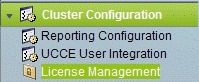 | ||
| Step 2 | Click Browse. | ||
| Step 3 | Navigate to the location where the *.lic file was saved. | ||
| Step 4 | Click
Apply
License to load the license.
A message appears indicating that the license file was uploaded successfully and will be distributed to other nodes (if any) in the cluster in approximately one minute.
|
What to Do Next
Configure Live Data AW-Access
Live Data AW DB access commands allow you to configure and view CCE AW DB (real-time distributor) access for Contact Center Enterprise Live Data Product Deployment Selection. You can also test the connection.
| Step 1 | Log in to
CUIC
Live Data Console and execute the following command:
set live-data aw-access primary addr port db user pwd [test] set live-data aw-access secondary addr port db user pwd [test]
| |||||||||||||||||||||
| Step 2 | Run the
following command to view the primary and secondary CCE AW DB access
information. Optional, test the connection from Live Data to each AW DB, check
if configured user (on each node) has appropriate AW DB access:
show live-data aw-access primary addr port db user pwd [test] show live-data aw-access secondary addr port db user pwd [test] |
Configure Live Data Machine Services
| Step 1 | Log in to CUIC Live Data Console. | |||||||||||
| Step 2 | Run the below
command to configure the latest information from Live Data with Machine Service
table.
| |||||||||||
| Step 3 | Run the below
command to view Live Data entries in the
Machine
Services table:
|
Configure Live Data Unified Intelligence Data Sources
| Step 1 | Run the
following command to configure the data source of Live Data in Cisco Unified
Intelligence Center:
| |||||||||||||||
| Step 2 | Run the
following command to display Data Source:
|
Configure Live Data Reporting Interval
| Step 1 | Log in to CUIC Live Data Console. | ||||||
| Step 2 | Run the
following command to set Live Data reporting interval in minutes format:
| ||||||
| Step 3 | After Live
Data reporting interval is set, run the below command to restart the publisher
and subscriber node (Restart the inactive node first and active node next):
| ||||||
| Step 4 | Run the below
command to view Live Data reporting interval:
|
Import Live Data Reports
Ensure that the data source is used to import report definition is configured in Unified Intelligence Center. Also, ensure that data source is used by any value list that is defined in Unified Intelligence Center, if the report definition has any value list defined.
Follow the below steps to import an existing Unified Intelligence Center stock reports and report definition.
| Step 1 | Click Reports in the left pane. |
| Step 2 | Click Import Report. |
| Step 3 | In File Name (XML File) field, click Browse to select the XML file. |
| Step 4 | Browse the report XML zip file and click Open. |
| Step 5 | In
Save
to filed, browse the folder where you want to place the imported
report definition.
Use arrow keys to expand the folders. |
| Step 6 | Click Import. |
| Step 7 | Choose Data Source for ReportDefinition from the drop-down list. |
| Step 8 | Choose Data Source for ValueList defined in report definition from the drop-down list. |
| Step 9 | Optional, in Save to filed, browse the folder where you want to place the imported report definition. |
| Step 10 | Click Import. |
Add Certificate for HTTPS Gadget
Add a certificate for a secure HTTP (HTTPS) gadget to allow the gadget to load into the Finesse desktop and successfully perform HTTPS requests to the Finesse server.
This process allows HTTPS communication between the Finesse gadget container and the third-party gadget site for loading the gadget and performing any API calls that the gadget makes to the third-party server.
Note | A gadget that loads using HTTPS may still use HTTP communication between that gadget and the application server where it resides. If all traffic must be secure, the gadget developer must ensure that HTTPS is used to make API calls to the application server. |
The certificate must be signed with a common name. The gadget URL in the desktop layout must use the same name (whether it uses an IP address or a fully qualified domain name) as the name with which the certificate is signed. If the certificate name and the name in the gadget URL do not match, the connection is not trusted and the gadget does not load.
Set up security certificates for finesse, Cisco Unified Intelligence Center and Live Data server to server communication. Import certificates into servers as shown in the table below:
|
Server |
Import Certificates |
|---|---|
|
Finesse |
Live Data and Cisco Unified Intelligence Center |
|
Cisco Unified Intelligence Center |
Live Data |
| Step 1 | Download the
tomcat-trust.pem certificate from the third-party gadget host.
|
| Step 2 | Upload the
certificate to the Finesse Publisher server.
|
| Step 3 | Restart Cisco Tomcat and Cisco Finesse Tomcat services on the Finesse Publisher server. |
| Step 4 | Ensure the certificates are synchronized in Finesse Subscriber server. |
| Step 5 | Restart Cisco Tomcat and Cisco Finesse Tomcat services on Finesse Subscriber server. |
Configure Cisco Finesse
This table lists the configuration procedures for Cisco Finesse:
| Sequence | Task | Done? |
|---|---|---|
| 1 | ||
| 2 |
Configure Settings for the CTI Server and Administration and Data Server |
|
| 3 | ||
| 4 | ||
| 5 | ||
| 6 |
- Configure the Cisco Finesse Primary Node
- Configure Settings for the CTI Server and Administration and Data Server
- Configure Cisco Finesse Secondary Node
- Configure Cisco Finesse Administration
- Configure SNMP
Configure the Cisco Finesse Primary Node
Note | You must configure the Cisco Finesse primary node before you customize the secondary node. |
Ensure that the Virtual Machine device status is Connect at Power On checked for the Network adapter and Floppy drive
| Step 1 | Power on the primary node. To begin the installation based on the information in the .flp file. The installation begins automatically and runs with no interaction from you. After an hour or more, a message appears indicating a successful installation. |
| Step 2 | Click the Console tab for the VM. Log in to the Finesse Primary machine, using the credentials for the Administration User. The machine opens to the CLI interface. |
| Step 3 | Right-click the VM and choose Edit settings and uncheck Connect at Power on for the floppy drive. |
Note | During the customization of the primary, the username and the password are modified as follows. The customer should change the password.
After rebooting, the VM installation is complete with all the parameters provided in the spreadsheet for the VM. |
Configure Settings for the CTI Server and Administration and Data Server
Configure CTI Server Settings in the Cisco Finesse Primary Node
| Step 1 | Launch the URL http://<HOST ADDRESS>/cfadmin, where Host Address is the hostname or IP address of your primary Cisco Finesse server. | ||||||||||||||||||||||||||||||
| Step 2 | Go to Home > Contact Center Enterprise CTI Server Settings. | ||||||||||||||||||||||||||||||
| Step 3 | Under Contact Center Enterprise CTI Server Settings, update the following: | ||||||||||||||||||||||||||||||
| Step 4 | Click
Save.
|
Configure Unified Contact Center Enterprise Administration and Data Server
| Step 1 | Select . (This menu structure assumes the default configuration.) |
| Step 2 |
Under Contact
Center Enterprise Administration & Data Server Settings, update
the following:
|
| Step 3 | Click Save. |
Restart the Cisco Tomcat Service
What to Do Next
For golden templates, configure the secondary node.
For direct installation, check the replication status.
Configure Cisco Finesse Secondary Node
Launch the Finesse Administration Console to Configure the Secondary Finesse
To add the secondary node, you must launch the primary node and add the secondary node to the cluster.
| Step 1 | Launch the Cisco Finesse primary node in a browser (http://Primary Node FQDN/cfadmin), where the primary node or IP address is that of your host. |
| Step 2 | Select Settings > Cluster Settings. (Cluster settings are based on the default configuration and assumes that you have not changed the page for the Cluster Settings tool.) |
| Step 3 | Add the IP address for the Cisco Finesse secondary node. |
| Step 4 | Click Save. |
| Step 5 | Restart Cisco Tomcat as follows: |
Install Cisco Finesse on the Secondary Node
Ensure that you select the Connect at Power on check box of the virtual machine for network adapter and floppy drive.
| Step 1 | Power on the secondary node to begin the installation based on the information in the .flp file. The installation begins automatically and runs with no interaction from you. After an hour or more, a message appears indicating a successful installation. |
| Step 2 | Click the Console tab for the virtual machine. Log into the Cisco Finesse secondary machine, using the credentials for the administration user. The machine opens to the CLI interface. |
| Step 3 | Right-click the virtual machine and choose Edit settings and uncheck Connect at Power on for the floppy drive. |
Note | During the customization of the secondary node, the username and the password is modified as follows. You can change the password:
|
Configure Cisco Finesse Administration
- Obtain and Upload a CA Certificate
- Trust Self-Signed Certificate for Cisco Finesse
- Browser Settings for Internet Explorer
Obtain and Upload a CA Certificate
Note | This procedure applies only if you are using HTTPS. This procedure is optional. If you are using HTTPS, you can choose to obtain and upload a CA certificate or you can choose to use the self-signed certificate provided with Cisco Finesse. |
To eliminate browser security warnings each time that you sign in, obtain an application and root certificate signed by a Certificate Authority (CA). Use the Certificate Management utility from Cisco Unified Operating System Administration.
To open Cisco Unified Operating System Administration, enter the following URL in your browser: https://FQDN of primary Finesse server:8443/cmplatform.
Sign in using the username and password for the application user account created during Cisco Finesse installation.
| Step 1 | Generate a CSR as follows. | ||
| Step 2 | Download the CSR. | ||
| Step 3 | Use the CSR to obtain the signed application certificate and the CA root certificate from the Certificate Authority. | ||
| Step 4 | When you receive the certificates, select Security > Certificate Management > Upload Certificate. | ||
| Step 5 | Upload the root certificate. | ||
| Step 6 | Upload the application certificate. | ||
| Step 7 | After the upload is complete, sign out from Cisco Finesse. | ||
| Step 8 | Access the CLI on the primary Cisco Finesse server. | ||
| Step 9 | Enter utils service restart Cisco Finesse Notification Service command to restart the Cisco Finesse Notification service. | ||
| Step 10 | Enter utils service restart Cisco Tomcat command to restart the Cisco Tomcat service. | ||
| Step 11 | Upload the
root certificate and application certificate to the secondary Cisco Finesse
server.
| ||
| Step 12 | Access the CLI on the secondary Cisco Finesse server and restart the Cisco Finesse Notification Service and the Cisco Tomcat Service. |
Trust Self-Signed Certificate for Cisco Finesse
After you define configuration settings, disable CSA, and restart services. Authorized agents can sign in to the Cisco Finesse Agent Desktop.
After you restart Cisco Finesse, it takes approximately 6 minutes for all server-related services to restart. Therefore, you should wait 6 minutes before you attempt to sign in to the Agent Desktop.
| Step 1 | Enter the following URL in browser: https://FQDN of Finesse server:8443/cmplatform. | ||||||||
| Step 2 | When you
access Agent Desktop for the first time using HTTPS, it prompts you to trust
the self-signed certificate provided with Cisco Finesse. Following table
describes the procedure for each supported browser.
|
Browser Settings for Internet Explorer
Configure the following privacy and advanced settings:
| Step 1 | From the browser menu bar, choose . |
| Step 2 | Click Privacy tab and click Sites. |
| Step 3 | In Address field, enter the domain name for side A of Cisco Finesse server. |
| Step 4 | Click Allow. |
| Step 5 | In Address field, enter the domain name for side B of Cisco Finesse server. |
| Step 6 | Click Allow and click OK. |
| Step 7 | Click Advanced tab on the Internet Options dialog box. |
| Step 8 | Uncheck Warn about certificate address mismatch check box, in Security pane. |
| Step 9 | Click Ok. |
What to Do Next
Configure SNMP
| Step 1 | Log in to the Cisco Unified Serviceability(https://hostname of primary server/ccmservice ) using administrator credentials. |
| Step 2 | Select . |
| Step 3 | From Server drop-down list, select the server for which you want to configure a community string and click Find. |
| Step 4 | Click
Add
New to add new community string.
|
| Step 5 | Select . |
| Step 6 | From Server drop-down list, select the server for which you want to configure a notification destination and click Find. |
| Step 7 | Click
Add
New button to add new notification destination.
|
Create a Customer Instance for the1000 Agent Deployment Model
Follow this sequence of tasks to create the customer instance to deploy 1000 agent for Cisco HCS for Contact Center.
| Sequence | Task | Done? |
|---|---|---|
| 1 |
|
|
| 2 | Set Up Virtual Machine Startup and Shutdown |
|
| 3 | Create a Domain Controller Server |
|
| 4 | Configure Cisco Unified CCE Call Server |
|
| 5 | Configure Unified CCE Data Server |
|
| 6 | Configure Unified CVP |
|
| 7 |
|
|
| 8 | Configure Unified Communications Manager |
|
| 9 |
|
|
| 10 | Configure Cisco Finesse |
|
Create a Customer Instance for the 4000 Agent Deployment Model
Follow this sequence of tasks to create the customer instance to deploy 4000 agent for Cisco HCS for Contact Center. After each task, return to this page to mark the task "done" and continue the sequence.
| Sequence | Task | Done? |
|---|---|---|
| 1 |
|
|
| 2 | Set Up Virtual Machine Startup and Shutdown |
|
| 3 | Create a Domain Controller Server |
|
| 4 | Configure Cisco Unified CCE Rogger |
|
| 5 | Configure Unified CCE AW-HDS-DDS |
|
| 6 | Configure Unified CCE Agent PG 1 |
|
| 7 | Configure Unified CCE Agent PG 2 |
|
| 8 | Configure Unified CCE VRU PG |
|
| 9 | Configure Unified CVP |
|
| 10 | Configure Cisco IOS Enterprise Voice Gateway |
|
| 11 | Configure Unified Communications Manager |
|
| 12 | Configure Unified Intelligence Center |
|
| 13 | Configure Live Data Reporting System |
|
| 14 | Configure Cisco Finesse |
|
Configure Cisco Unified CCE Rogger
This table lists the configuration procedures you must perform to configure Cisco Unified CCE Rogger.
| Sequence | Task | Done? |
|---|---|---|
| 1 | ||
| 2 | Verify the Machine in Domain | |
| 3 | Configure the Domain Manager | |
| 4 | ||
| 5 | ||
| 6 | ||
| 7 | ||
| 8 | ||
| 9 | ||
| 10 | ||
| 11 |
Configure the Unified CCE Router
| Step 1 | Launch the Unified CCE Web Setup. | ||
| Step 2 | Sign in as the domain user with local Administrator permission. | ||
| Step 3 | Click Instance Management, and then click Add. | ||
| Step 4 | In the Add Instance window, select Facility and Instance from the drop-down list. | ||
| Step 5 | In the Instance Number field, enter 0. Click Save . | ||
| Step 6 | Select . | ||
| Step 7 | Click Add to set up the Call Router. | ||
| Step 8 | In the Deployment window, select the appropriate Side. | ||
| Step 9 | Select Duplexed as Fault Tolerance Mode. Click Next. | ||
| Step 10 | In the Router Connectivity window, configure the Private Interface and Public (Visible) Interfaces. Click Next. | ||
| Step 11 | In the Enable Peripheral Gateways dialog box, enter the following in the Enable Peripheral Gateways field. Click Next. | ||
| Step 12 | In the Router Options window, configure as follows: | ||
| Step 13 | In Router Quality of Service window, click Next. (Applicable to Side A only.) | ||
| Step 14 | In the
Summary window, make sure that the router
summary is correct, then click
Finish.
|
What to Do Next
To enable the DNWildcard, select the Registry > HKEY_LOCAL_MACHINE > SOFTWARE > Cisco Systems > ICM > <instance> >RouterA > Router > CurrentVersion > Configurations > Global, and select the DNWildcardEnabled and set to 1.
Configure the Unified CCE Logger
Note | Ensure that your browser is enabled. |
| Step 1 | Launch the Unified CCE Web Setup. | ||
| Step 2 | Sign in using as domain user having local Administrator permissions. | ||
| Step 3 | Click Instance Management, and then click Add. | ||
| Step 4 | In the Add Instance window, select Facility and Instance from the drop-down list. | ||
| Step 5 | In the Instance Number field, enter 0 and click Save. | ||
| Step 6 | Configure
the logger database as follows:
| ||
| Step 7 | In Create Database window, configure the following to create the Log: | ||
| Step 8 | In Add Device dialog box, configure as follows: | ||
| Step 9 | In Create Database window, in Storage section, click Add. | ||
| Step 10 | In Add Device dialog box, configure as follows: | ||
| Step 11 | In
Create Database window, click
Create and click
Start.
When you see the successful creation message, click OK and click Close. | ||
| Step 12 | Configure
the logger component as follows:
| ||
| Step 13 | In Additional Options window, configure as follows: | ||
| Step 14 | In Data Retention window, in the data retention table, retain the default values and click Next. | ||
| Step 15 | In Data Purge window, configure purge for a time when there is low demand on the system. Click Next. | ||
| Step 16 | Review
Summary window, and then click
Finish.
|
What to Do Next
Set database and log file size, see Database and Log File Size.
Database and Log File Size
Complete the following procedure to increase the database and log sizes.
Use DB Estimator Tool to calculate database and log file size.
Alternative option is to size the database and log using the values from Table 1. The values in the table for HCS 500 and 1000 agent deployments are sized without considering optional HDS.| Step 1 | Open SQL Server 2014 Management Studio. | ||||||||||||||||
| Step 2 | Click Connect. In the left pane, expand Databases. | ||||||||||||||||
| Step 3 | Right-click Logger database [<Instance>_<Side>] and select Properties.. | ||||||||||||||||
| Step 4 | In the left pane, select Files. Ensure that Auto Growth is disabled for data and log files. | ||||||||||||||||
| Step 5 | Set the
initial size of the data and log files according to
DB Estimator Tool or
from the following table:
|
Load Base Configuration
Complete this procedure to upload the following base configuration parameters. For more information on base configuration parameter see Base Configuration Parameters for 4000 Agent Deployment.
| Step 1 | Download the HCS-10(1)-4000-Agent-Day1-Configuration.zip file. Save it locally and unzip it. |
| Step 2 | Download the Domain_Update_Tool.zip file. Save it locally and unzip it. |
| Step 3 | Copy the configuration folder to the local drive of CCE Rogger on Side A. |
| Step 4 | Open the ICMDBA Tool on the CCE Rogger on Side A. |
| Step 5 | Select the CCE Rogger and expand the tree to <instance name>_sideA. |
| Step 6 | Select Data on the menu bar and click Import. |
| Step 7 | Browse to locate the configuration folder and click Open. |
| Step 8 | Click OK and then click Import. |
| Step 9 | Click Start and then click OK on all messages. |
| Step 10 | Navigate to the folder Domain_Update_Tool and right-click UpdateDomain.PS1. and Run with PowerShell. Respond as follows: |
| Step 11 | Return to the ICMDBA tool. Select Logger <instance name> database for the side that you want to synchronize. |
| Step 12 | Click Data in menu bar and select Synchronize and perform the following: |
| Step 13 | Click Start. After synchronization click OK. |
Configure Unified CCE AW-HDS-DDS
This section explains the configuration procedures you must perform for the Unified CCE AW-HDS-DDS for Sides A and B.
| Sequence | Task | Done? |
|---|---|---|
| 1 | ||
| 2 | ||
| 3 | ||
| 4 | ||
| 5 | ||
| 6 | ||
| 7 | ||
| 8 | ||
| 9 |
AW-HDS-DDS
Create Instance
| Step 1 | Launch Unified Contact Center Enterprise Web Setup from the desktop and log in using the Domain Administrator credentials to complete the installation. |
| Step 2 | Click Instance Management, and then click Add. |
| Step 3 | In the Add Instance window, select Facility and Instance from the drop-down list. |
| Step 4 | In the Instance Number field, enter 0. Click Save. |
Create HDS Database
| Step 1 | Configure the HDS database as follows: |
| Step 2 | In the Select Component dialog box, choose Administration & Data Server from the drop-down list. Click OK. |
| Step 3 | At the prompt, SQL Server is not configured properly. Do you want to configure it now?" Click Yes. |
| Step 4 | On the Configure page, in the SQL Server Configurations pane check Memory (MB) and Recovery Interval. Click OK. |
| Step 5 | On the Stop Server page, click Yes to stop the services. |
| Step 6 | In the Select AW Type dialog box, choose Enterprise from drop-down list. Click OK. |
| Step 7 | In the Create Database dialog box, configure as follows: |
| Step 8 | In the Add Device dialog box, configure as follows: |
| Step 9 | In the Create Database dialog box, under Storage, click Add. |
| Step 10 | In the Add Device dialog box, configure as follows: |
| Step 11 | In the Create Database dialog box, configure as follows: |
Configure AW-HDS-DDS
Complete the following procedure to install the Cisco Unified CCE Administration Server & Real-time Data Server, Historical Data Server, and Detailed Data Server (AW-HDS-DDS).
| Step 1 | Choose Component Management > Administration & Data Servers. | ||
| Step 2 | Click Add. | ||
| Step 3 | On the Deployment window, choose the current instance. | ||
| Step 4 | On the Add Administration & Data Servers window, configure as follows: | ||
| Step 5 | On the Server Role in a Small to Medium Deployment window, configure as follows: | ||
| Step 6 | On the
Administration & Data Servers Connectivity window, configure as follows:
| ||
| Step 7 | On the Database and Options window, configure as follows: | ||
| Step 8 | On the Central
Controller Connectivity window, configure as follows:
| ||
| Step 9 | Review the
Summary window, and click
Finish.
|
Database and Log File Size
Complete the following procedure to increase the database and log sizes.
Use DB Estimator Tool to calculate database and log file size.
Alternative option is to size the database and log using the values from Table 1.| Step 1 | Open Microsoft SQL Server Management Studio. | ||||||
| Step 2 | Expand the Database in Object Explorer. | ||||||
| Step 3 | Choose HDS database. Right-click on the database and select Properties. | ||||||
| Step 4 | Click Files to increase the database and log sizes. | ||||||
| Step 5 | Ensure that Auto Growth is disabled for data and log files. | ||||||
| Step 6 | Set the initial size of the data and log files according to
DB
Estimator Tool or from the following table:
|
Configure Unified CCE Agent PG 1
This section explains the configuration procedures you must perform for the Unified CCE Agent PG on both the side A and B.
| Sequence | Task | Done? |
|---|---|---|
| 1 | ||
| 2 | ||
| 3 | ||
| 4 |
Configure CUCM Peripheral Gateway for 4000 Agent Deployment Model |
|
| 5 | ||
| 6 | ||
| 7 | ||
| 8 | ||
| 9 | ||
| 10 |
Configure CUCM Peripheral Gateway for 4000 Agent Deployment Model
Complete the following tasks to configure the Unified CCE peripheral gateways for the PG Server on Side A and then repeat the same procedure for Side B.
Prepare to Add PIMs
Complete the following procedure to prepare to add PIMs (Peripheral Interface Manager).
| Step 1 | Choose . |
| Step 2 | Click Add in the ICM Instances pane. |
| Step 3 | In the Add Instance window, select Facility and Instance from the drop-down list. |
| Step 4 | Enter 0 in the Instance Number field. Click Save. |
| Step 5 | Click Add in the Instance Components pane, and from the Component Selection dialog box choose Peripheral Gateway. |
| Step 6 | In the
Peripheral Gateway Properties dialog box:
|
Add PIM1(CUCM PIM)
| Step 1 | Check Enabled. |
| Step 2 | In the Peripheral name field, enter CUCM_PG_1 for Agent PG1 or enter CUCM_PG_2 for Agent PG2. |
| Step 3 | In the Peripheral ID field, enter 5000 for Agent PG1 or enter 5001 for Agent PG2. |
| Step 4 | In the Agent extension length field, enter extension length for this deployment. |
| Step 5 | In the CUCM Parameters pane, configure as follows: |
| Step 6 | Click OK. |
After Creating PIMs
| Step 1 | Enter 5000 for Agent PG1 or enter 5001 for Agent PG2 in the Logical Controller ID field. | ||
| Step 2 | Enter 0 in the CTI Call Wrapup Data delay field. | ||
| Step 3 | In the Device
Management Protocol Properties dialog box, configure as follows:
| ||
| Step 4 | In the Peripheral Gateway Network Interfaces dialog box, enter the PG Private Interfaces and the PG Public (Visible) Interfaces. | ||
| Step 5 | Click the
QoS button
in the private interfaces section for Side A. In the PG Private Link QoS
Settings, check the check box
Enable QoS
and click
OK.
This step applies only to Side A. | ||
| Step 6 | Click the
QoS button in the public interfaces section. In the
PG Visible Link QoS Settings, check
Enable
QoS and click
OK.
This step applies only to Side A. | ||
| Step 7 | In the Peripheral Gateway Network Interfaces dialog box, click Next. | ||
| Step 8 | In the Check Setup Information dialog box, click Next. | ||
| Step 9 | In the
Setup
Complete dialog box, click
Finish.
|
Configure Media Routing Peripheral Gateway
Complete the following procedures to configure the Unified CCE Media Routing Peripheral Gateway for the Agent PG on Side A and then repeat for Side B. The Media Routing Peripheral Gateway has two PIMs-the MultiChannel PIM and the Outbound PIM.
You must configure this PG, even if Multichannel and Outbound are not used. In that case, this PG remains idle or can be disabled.
Configure Multichannel and Outbound PIM's 4000 Agent Deployment
Complete the following procedure to configure multichannel and outbound PIM's.
| Step 1 | Choose . | ||
| Step 2 | Click Add in the Instance Components pane, and from the Component Selection dialog box choose Peripheral Gateway. | ||
| Step 3 | In the Peripheral Gateway Properties dialog box: | ||
| Step 4 | In the
Peripheral Interface Manager pane of the
Peripheral Gateway Component Properties dialog box,
click
Add
and configure PIM1 with the Client Type of Media Routing
as follows:
| ||
| Step 5 | Click
Add and configure
PIM2 with the client type of Media Routing as
follows:
| ||
| Step 6 | Enter 5003 in the Logical Controller ID field. | ||
| Step 7 | Enter 0 in the CTI Call Wrapup Data delay field. Click Next. | ||
| Step 8 | In the
Device Management Protocol Properties dialog box, configure as follows:
| ||
| Step 9 | In the
Peripheral Gateway Network Interfaces dialog box,
enter the PG Private Interfaces and the PG Public (Visible) Interfaces.
This step applies only to Side A. | ||
| Step 10 | In the Check Setup Information dialog box, click Next. | ||
| Step 11 | In the Setup Complete dialog box, click Finish. | ||
| Step 12 | Click
Exit
Setup.
|
Install JTAPI
Note | This procedure is required for the Unified Contact Center Enterprise Machine having a PG with Unified Communications Manager PIM. However, you must postpone this task until after you Configure Unified Communications Manager. |
Complete the following procedure to install JTAPI on the Unified Contact Center Enterprise Machine having a PG with Unified Communications Manager PIM for Side A and Side B.
| Step 1 | Launch the Unified Communications Manager in a browser (https://{callmanager-hostname}) and log in. |
| Step 2 | Navigate to . Click Find. |
| Step 3 | Download the Cisco JTAPI 32-bit Client for Windows. |
| Step 4 | Install the downloaded file, accepting all of the default settings. |
| Step 5 | At the prompt, enter the IP address for the Unified Communications Manager TFTP Server, and click Next. |
| Step 6 | Click Finish. |
Configure CTI Server
| Step 1 | Choose Start > All Programs > Cisco Unified CCE Tools > Peripheral Gateway Setup. | ||
| Step 2 | In the Instance Components pane of the Components Setup dialog box click Add. | ||
| Step 3 | In the
Component Selection dialog box, click
CTI
Server.
| ||
| Step 4 | In the Server Component Properties dialog box, configure as follows: | ||
| Step 5 | Click Next. | ||
| Step 6 | In the Network Interface Properties dialog box, enter the private interfaces. | ||
| Step 7 | Enter the public (visible) interfaces and the CG visible interfaces, and click Next. | ||
| Step 8 | Under the Check Setup Information page, verify all the settings, and click Next. | ||
| Step 9 | In the Setup Completed dialog box, click Finish. | ||
| Step 10 | Click
Exit
Setup.
|
Configure Unified CCE Agent PG 2
This section explains the configuration procedures you must perform for the Unified CCE Agent PG 2 Sides A and B.
| Sequence | Task | Done? |
|---|---|---|
| 1 | ||
| 2 | ||
| 3 | ||
| 4 |
Configure CUCM Peripheral Gateway for 4000 Agent Deployment Model |
|
| 5 | ||
| 6 | ||
| 7 | ||
| 8 | ||
| 9 | ||
| 10 |
Configure Outbound PIM for 4000 Agent Deployment
Complete the following procedure to configure the outbound PIM.
| Step 1 | Choose Start > All programs > Cisco Unified CCE Tools >Peripheral Gateway Setup. | ||
| Step 2 | Click Add in the Instance Components pane, and from the Component Selection dialog box and choose Peripheral Gateway. | ||
| Step 3 | In the Peripheral Gateway Properties dialog box: | ||
| Step 4 | In the
Peripheral Interface Manager pane of the Peripheral Gateway Component
Properties dialog box, click
Add and configure PIM1 with the Client Type of Media
Routing as follows:
| ||
| Step 5 | Enter 5004 for PG5 in the Logical Controller ID field. Leave all other fields with default values and click Next. | ||
| Step 6 | In the
Device Management Protocol Properties dialog box, configure as follows:
| ||
| Step 7 | In the Peripheral Gateway Network Interface dialog box, enter the PG Private interface and PG Public (visible) interfaces. Click Next. | ||
| Step 8 | Click the
QoS
button in the private interfaces section for Side A. In the PG Private Link QoS
Settings, check
Enable
QoS and click
OK.
This step applies only to Side A. | ||
| Step 9 | Click the
QoS
button in the visible interfaces section. In the PG Visible Link QoS Settings,
check
Enable
QoS, click
OK and
click
Next.
This step applies only to Side A. | ||
| Step 10 | Click Next on the Check Setup Information dialog box. | ||
| Step 11 | In the Setup Complete dialog box, click Finish. | ||
| Step 12 | Click
Exit
Wizard.
|
Configure Unified CCE VRU PG
This table lists the configuration procedures you must perform for the Unified CCE VRU PG for Sides A and Side B.
| Sequence | Task | Done? |
|---|---|---|
| 1 | ||
| 2 | ||
| 3 | ||
| 4 | ||
| 5 | ||
| 6 |
Configure VRU PG
Complete the following tasks to configure the Unified CCE peripheral gateways for the PG Server on Side A and then repeat the same procedure for Side B.
Prepare to Add PIMs
Complete the following procedure to prepare to add PIMs (Peripheral Interface Manager).
| Step 1 | Choose . |
| Step 2 | Click Add in the ICM Instances pane. |
| Step 3 | In the Add Instance window, select Facility and Instance from the drop-down list. |
| Step 4 | Enter 0 in the Instance Number field. Click Save. |
| Step 5 | Click Add in the Instance Components pane, and from the Component Selection dialog box choose Peripheral Gateway. |
| Step 6 | In the Peripheral Gateway Properties dialog box: |
Add VRU PIMs
| Step 1 | Check Enabled. | |||||||||||||||||||||||||||||||||||||||||||||||||||||||||||||||||||||||||||||||||||||
| Step 2 | In the
Peripheral Name,
Peripheral ID, and
VRU
host name fields, enter the following values respective to the CVP
servers:
| |||||||||||||||||||||||||||||||||||||||||||||||||||||||||||||||||||||||||||||||||||||
| Step 3 | In the VRU connect port field, enter 5000. | |||||||||||||||||||||||||||||||||||||||||||||||||||||||||||||||||||||||||||||||||||||
| Step 4 | In the Reconnect interval (sec) field, enter 10. | |||||||||||||||||||||||||||||||||||||||||||||||||||||||||||||||||||||||||||||||||||||
| Step 5 | In the Heartbeat interval (sec) field, enter 5. | |||||||||||||||||||||||||||||||||||||||||||||||||||||||||||||||||||||||||||||||||||||
| Step 6 | In the DSCP field, choose CS(324). | |||||||||||||||||||||||||||||||||||||||||||||||||||||||||||||||||||||||||||||||||||||
| Step 7 | Click OK. | |||||||||||||||||||||||||||||||||||||||||||||||||||||||||||||||||||||||||||||||||||||
| Step 8 | Repeat the above steps for the remaining PIMs. |
After Creating PIMs
| Step 1 | Enter the appropriate Peripheral ID in the Logical Controller ID field. | ||
| Step 2 | Enter 0 in the CTI Call Wrapup Data delay field. | ||
| Step 3 | In the VRU Reporting pane, select Service Control and check Queue Reporting. Click Next. | ||
| Step 4 | In the Device
Management Protocol Properties dialog box, configure as follows:
| ||
| Step 5 | In the Peripheral Gateway Network Interfaces dialog box, enter the PG Private Interfaces and the PG Public (Visible) Interfaces. | ||
| Step 6 | Click the
QoS button
in the private interfaces section for Side A. In the PG Private Link QoS
Settings, check the check box
Enable QoS
and click
OK.
This step applies only to Side A. | ||
| Step 7 | Click the QoS
button in the Public (Visible) Interfaces section. In the PG Visible Link QoS
Settings, check the check box
Enable
QoS, click
OK and
click
Next.
This step applies only to Side A. | ||
| Step 8 | In the Peripheral Gateway Network Interfaces dialog box, click Next. | ||
| Step 9 | In the Check Setup Information dialog box, click Next. | ||
| Step 10 | In the
Setup
Complete dialog box, click
Finish.
|
Configure Unified Intelligence Center
| Sequence | Task | Done? |
|---|---|---|
| 1 | Configure Unified Intelligence Center Publisher | |
| 2 | Configure Unified Intelligence Center Subscriber | |
| 3 | ||
| 4 | ||
| 5 | ||
| 6 |
Configure Live Data Reporting System
| Sequence | Task | Done? |
|---|---|---|
| 1 | Configure Live Data AW-Access | |
| 2 | Configure Live Data Machine Services | |
| 3 | Configure Live Data Unified Intelligence Data Sources | |
| 4 | Configure Live Data Reporting Interval | |
| 5 | Import Live Data Reports | |
| 6 | Add Certificate for HTTPS Gadget |
Create Customer Instance for Small Contact Center Agent Deployment Model
Follow these sequence of tasks to create the customer instance to deploy small agent for Cisco HCS for Contact Center. After each task, return to this page and mark the task “done” and continue the sequence.
| Sequence | Task | Done |
|---|---|---|
| 1 | Upgrade VMware Tools | |
| 2 | Set Up Virtual Machine Startup and Shutdown | |
| 3 | Create DNS Server for Finesse in Small Contact Center Deployment | |
| 4 | Configure Unified CCE Rogger for Small Contact Center Agent Deployment | |
| 5 | Configure Unified CCE AW-HDS-DDS | |
| 6 | Configure Unified CCE VRU PG | |
| 7 | Configure Unified CVP | |
| 8 | ||
| 9 | Configure Unified Intelligence Center |
| Sequence | Task | Done |
|---|---|---|
| 1 | Set Up Virtual Machine Startup and Shutdown | |
| 2 | Configure Unified CCE Agent PG for Small Contact Center Agent Deployment | |
| 3 | Configure Unified Communications Manager | |
| 4 | Increase the SW MTP and SW Conference Resources | |
| 5 | Configure Cisco Finesse |
| Sequence | Task | Done |
|---|---|---|
| 1 | Set Up Virtual Machine Startup and Shutdown | |
| 2 | Configure Unified CCE Agent PG for Small Contact Center Agent Deployment | |
| 3 | Configure Shared Unified Communications Manager | |
| 4 | Configure Cisco Finesse |
After creating customer instance for shared core components and sub customer components for small contact center agent deployment, configure unified CCDM to integrate with the Internet Script Editor. See Integration of Small Contact Center Agent Deployment for Partition Internet Script Editor with CCDM
- Configure Unified CCE Rogger for Small Contact Center Agent Deployment
- Configure Unified CCE Agent PG for Small Contact Center Agent Deployment
- Increase the SW MTP and SW Conference Resources
- Configure Shared Unified Communications Manager
- Create DNS Server for Finesse in Small Contact Center Deployment
Configure Unified CCE Rogger for Small Contact Center Agent Deployment
This section explains the configuration procedures you must perform for the Unified CCE Rogger.
| Sequence | Task | Done? |
|---|---|---|
| 1 | ||
| 2 | Verify the Machine in Domain | |
| 3 | Configure the Domain Manager | |
| 4 | ||
| 5 | ||
| 6 | ||
| 7 | ||
| 8 | ||
| 9 |
Load Base Configuration for Small Contact Center Agent Deployment |
|
| 10 | ||
| 11 |
- Load Base Configuration for Small Contact Center Agent Deployment
- Configure Unified CCE Router for Small Contact Center
Load Base Configuration for Small Contact Center Agent Deployment
Complete this procedure to upload the following base configuration parameters. For more information on base configuration parameter see Base Configuration Parameters for Small Contact Center Agent Deployment.
| Step 1 | Download the HCS-10(1)-100-Agent-Day1-Configuration.zip file. Save it locally and unzip it. |
| Step 2 | Download the Domain_Update_Tool.zip file. Save it locally and unzip it. |
| Step 3 | Copy the configuration folder to the local drive of CCE Rogger on Side A. |
| Step 4 | Open the ICMDBA Tool on the CCE Rogger on Side A. |
| Step 5 | Select the CCE Rogger and expand the tree to <instance name>_sideA. |
| Step 6 | Select Data on the menu bar and click Import. |
| Step 7 | Browse to locate the configuration folder and click Open. |
| Step 8 | Click OK and then click Import. |
| Step 9 | Click Start and then click OK on all messages. |
| Step 10 | Navigate to the folder Domain_Update_Tool and right-click UpdateDomain.PS1. and Run with PowerShell. Respond as follows: |
| Step 11 | Return to the ICMDBA tool. Open Data on the menu bar and click Synchronize. |
| Step 12 | Click Start and then click OK on all messages. |
Configure Unified CCE Router for Small Contact Center
Complete the following procedure to configure the Unified CCE Router.
| Step 1 | Launch the Unified CCE Web Setup. | ||
| Step 2 | Sign in as the domain user with local Administrator permission. | ||
| Step 3 | Navigate to Component Management > Routers. | ||
| Step 4 | Click Add to set up the Call Router. | ||
| Step 5 | In the Deployment window, select the appropriate Side . | ||
| Step 6 | Select Duplexed and click Next. | ||
| Step 7 | In the Router Connectivity window, configure the Private Interface and Public (Visible) Interfaces. Click Next. | ||
| Step 8 | In the Enable Peripheral Gateways dialog box, enter 1-80 in the Enable Peripheral Gateways field. Click Advanced below to expand. | ||
| Step 9 | Under Advanced, in the Enable Peripheral Gateway dialog box, enter 81-150. Click Next . | ||
| Step 10 | In the Router Options window, configure the following, and click Next . | ||
| Step 11 | In Router Quality of Service window, click Next . | ||
| Step 12 | In the
Summary
window, make sure that the Router summary is correct, then click
Finish .
|
Configure Unified CCE Agent PG for Small Contact Center Agent Deployment
This section explains the configuration procedures you must perform for the Unified CCE Agent PG for small contact center agent deployment Sides A and B.
| Sequence | Task | Done? |
|---|---|---|
| 1 |
|
|
| 2 |
|
|
| 3 |
|
|
| 4 |
|
|
| 5 |
Configure CUCM Peripheral Gateway for Small Contact Center Agent Deployment Model |
|
| 6 |
Configure Media Routing Peripheral Gateway for Small Contact Center Agent Deployment Model |
|
| 7 |
Configure CTI Server for Small Contact Center Agent Deployment Model |
|
| 8 |
|
|
| 9 |
|
|
| 10 |
|
|
| 11 |
- Configure CUCM Peripheral Gateway for Small Contact Center Agent Deployment Model
- Configure CTI Server for Small Contact Center Agent Deployment Model
- Configure Media Routing Peripheral Gateway for Small Contact Center Agent Deployment Model
Configure CUCM Peripheral Gateway for Small Contact Center Agent Deployment Model
Complete the following tasks to configure the Unified CCE peripheral gateways for the PG Server on Side A and then repeat the same procedure for Side B.
- Add Agent PG Using Unified CCE Configuration Manager
- Prepare to Add PIMs
- Add PIM1(CUCM PIM)
- After Creating PIMs
Add Agent PG Using Unified CCE Configuration Manager
Complete the following procedure to add an Agent PG using Unified CCE Configuration Manager.
| Step 1 | On the Unified CCE Admin Workstation Server, navigate to Start > Cisco Unified CCE Tools > Administration Tools > Configuration Manager. |
| Step 2 | In Configuration Manager Window, expand Tools > Explorer Tools and open PG Explorer. |
| Step 3 | Click Add PG and enter the following values in Logical Controller pane. |
| Step 4 | Click on the Peripheral under PG and enter the following values in Peripheral tab. |
| Step 5 | Click on the Routing client tab and enter a name for Routing client. |
| Step 6 | Click Save and Close. |
| Step 7 | In the Configuration Manager window, choose Tools > Explorer Tools > Network VRU Explorer . |
| Step 8 | Choose Retrieve > CVP_Network_VRU > Add Label, enter the routing client you have created in Step 5 and enter the label value as 7777777777 . |
| Step 9 | Click Save and Close. |
| Step 10 | In Configuration Manager window, choose List Tools > Agent Targeting. |
| Step 11 | Click Retrieve > Select Add > In the Attributes field Enter Name > Select the Peripheral as CUCM PG > Select the Rule Type as Agent Extension > Routing Client > Add and select the newly added Routing Client and all the CVP routing clients available > Extension Range > Add the supported extension range. |
| Step 12 | Click Save and Close. |
Prepare to Add PIMs
Complete the following procedure to prepare to add PIMs (Peripheral Interface Manager).
| Step 1 | Choose Start > All Programs > Cisco Unified CCE Tools > Peripheral Gateway Setup. |
| Step 2 | Click Add in the ICM Instances pane. |
| Step 3 | In the Add Instance window, select Facility and Instance from the drop-down list. |
| Step 4 | Enter 0 in the Instance Number field. Click Save. |
| Step 5 | Click Add in the Instance Components pane, and from the Component Selection dialog box choose Peripheral Gateway. |
| Step 6 | In the Peripheral Gateway Properties dialog box: |
Add PIM1(CUCM PIM)
In the Peripheral Interface Manager pane of the Peripheral Gateway Component Properties dialog box, click Add and configure PIM1 with the Client Type of Unified Communications Manager as follows:
| Step 1 | Check Enabled. |
| Step 2 | In the Peripheral name field, enter CUCM_PG_XX, where XX is the Agent PG number |
| Step 3 | In the Peripheral ID field, Refer to PG explorer and enter the value. |
| Step 4 | In the Agent extension length field, enter 8 as extension length for this deployment. |
| Step 5 | In the CUCM Parameters pane, configure as follows: |
| Step 6 | Click OK. |
After Creating PIMs
| Step 1 | Refer to PG Explorer and Enter the value in the Logical Controller ID field. | ||
| Step 2 | Enter 0 in the CTI Call Wrapup Data delay field and Click Next. | ||
| Step 3 | In the Device
Management Protocol Properties dialog box, configure as follows:
| ||
| Step 4 | In the Peripheral Gateway Network Interfaces dialog box, enter the Private Interfaces and the Public (Visible) Interfaces. | ||
| Step 5 | Click the QoS button in the private interfaces section for Side A. In the PG Private Link QoS Settings, check the check box Enable QoS and click OK. This step applies only to Side A. | ||
| Step 6 | Click the QoS button in the public (visible) interfaces section. In the PG Visible Link QoS Settings, check Enable QoS and click OK. This step applies only to Side A. | ||
| Step 7 | In the Peripheral Gateway Network Interfaces dialog box, click Next. | ||
| Step 8 | In the Check Setup Information dialog box, click Next. | ||
| Step 9 | In the
Setup Complete
dialog box, click
Finish.
|
Configure CTI Server for Small Contact Center Agent Deployment Model
Complete the following procedure to configure the CTI server for Side A and Side B.
| Step 1 | Choose Start > All Programs > Cisco Unified CCE Tools > Peripheral Gateway Setup. | ||
| Step 2 | In the Instance Components pane of the Components Setup dialog box click Add. | ||
| Step 3 | In the Component Selection dialog box, click CTI Server. | ||
| Step 4 | In the Server Component Properties dialog box, configure as follows: | ||
| Step 5 | Click Next. | ||
| Step 6 | In the CTI Server Network Interface Properties dialog box, enter the PG private interfaces, CG private interfaces, and CG visible interfaces details and click Next. | ||
| Step 7 | Under the Check Setup Information page, verify all the settings, and click Next. | ||
| Step 8 | In the Setup Completed dialog box, click Finish. | ||
| Step 9 | Click Exit Setup.
|
Configure Media Routing Peripheral Gateway for Small Contact Center Agent Deployment Model
Add Media Routing PG Using Unified CCE Configuration Manager
Complete the following procedure to add a Media Routing PG using Unified CCE Configuration Manager.
| Step 1 | On the Unified CCE Admin Workstation Server, navigate to Start > Cisco Unified CCE Tools > Administration Tools > Configuration Manager. |
| Step 2 | In Configuration Manager Window, expand Tools > Explorer Tools and open PG Explorer. |
| Step 3 | Click Add PG and enter the following values in Logical Controller pane. |
| Step 4 | Click on the Peripheral under PG and enter the following values. |
| Step 5 | Click (2) Add Peripheral button and enter the following values. |
| Step 6 | Click Save and Close. |
| Step 7 | In Configuration Manager, Click List Tools, Select Agent Targeting Rule. |
| Step 8 | Click Retrieve, Select Add, In the Attributes Tab Enter Name, In the Peripheral list, Select CUCM PG, Select Rule Type as Agent Extension, In the Routing Client section, Select Add and select the newly added Outbound Routing Client, Click OK. In the Extension Ranges section, Click Add and Provide the supported extension range, Click OK. |
| Step 9 | Click Save and Close. |
Configure Media Routing Peripheral Gateway for Small Contact Center Agent Deployment Model
Complete the following procedure to configure Media Routing Peripheral gateway on Side A and then repeat the same procedure for Side B.
| Step 1 | Choose Start > Programs > Cisco Unified CCE Tools > Peripheral Gateway Setup. | ||
| Step 2 | Click Add in the Instance Components pane, and from the Component Selection dialog box choose Peripheral Gateway. | ||
| Step 3 | In the Peripheral Gateway Properties dialog box: | ||
| Step 4 | In the
Peripheral Interface Manager pane of the Peripheral Gateway Component
Properties dialog box, click Add and configure PIM1 with the Client Type of
Media Routing as follows:
| ||
| Step 5 | Click Add
and configure PIM2 with the client type of Media Routing as follows:
| ||
| Step 6 | Enter the Logical Controller ID field.Get the ID from PG explorer. | ||
| Step 7 | Enter 0 in the CTI Call Wrapup Data delay field. Click Next. | ||
| Step 8 | In the
Device Management Protocol Properties dialog box, configure as follows:
| ||
| Step 9 | In the Peripheral Gateway Network Interfaces dialog box, enter the Private Interfaces and the Visible Interfaces details. This step applies only to Side A. | ||
| Step 10 | In the Check Setup Information dialog box, click Next. | ||
| Step 11 | In the Setup Complete dialog box, click Finish. | ||
| Step 12 | Click Exit
Setup.
|
Increase the SW MTP and SW Conference Resources
| Step 1 | Login to the CUCM Administration web page. |
| Step 2 | Under the System tab, select the Service Parameter. |
| Step 3 | Select the CUCM server from the drop-down list. |
| Step 4 | Select the Cisco IP Voice Media Streaming App service. |
| Step 5 | Modify the
Conference Bridge (CFB) parameters and the Media Termination Point (MTP)
parameters field as following:
|
Configure Shared Unified Communications Manager
Follow this sequence of tasks to configure shared Unified Communications Manager:
| Sequence | Task | Done? |
|---|---|---|
| 1 | ||
| 2 | ||
| 3 | ||
| 4 | ||
| 5 | ||
| 6 | ||
| 7 | ||
| 8 | ||
| 9 | ||
| 10 | ||
| 11 | ||
| 12 |
Create DNS Server for Finesse in Small Contact Center Deployment
Few VOS machines (like Finesse) require a DNS server resolution to be locally available in the same network for successful VOS installation. It is recommended to install DNS in the Sub customer network for Small Contact Center deployment.
Complete the following procedures to create DNS server:
Enable DNS server
| Step 1 | Login in the Server machine in Sub customer network |
| Step 2 | Navigate to Administrative Tools > Server Manager |
| Step 3 | On Left side pane, Click Roles. |
| Step 4 | In the Roles window, Click Add Roles. |
| Step 5 | Click Next in the Add Roles Wizard. |
| Step 6 | In Select Server Roles window, Check DNS Server. Click Next. |
| Step 7 | In DNS server Window, Click Next. |
| Step 8 | In Confirm Installation Selections, Click Install and Close Wizard after installation. |
Configure DNS Server
| Step 1 | Navigate to . | ||
| Step 2 | Expand the Server on Left side pane. | ||
| Step 3 | Right-click on Forward Lookup Zones and Click New Zone. | ||
| Step 4 | In the New Zone Wizard, Click Next. | ||
| Step 5 | In the Zone type window, choose Primary zone. Click Next. | ||
| Step 6 | In the Zone Name window, Enter the Fully qualified DNS name. Click Next. | ||
| Step 7 | In Zone File window, Choose Create a new file with this file name. Click Next. | ||
| Step 8 | In the Dynamic Update window, Choose Do not allow dynamic updates. Click Next | ||
| Step 9 | Click Finish. | ||
| Step 10 | Right-click on Reverse Lookup Zones and Click New zone. | ||
| Step 11 | In the New Zone Wizard, Click Next | ||
| Step 12 | In the Zone type window, choose Primary zone. Click Next. | ||
| Step 13 | In the Reverse Lookup Zone Name, choose IPv4 Reverse Lookup Zone. Click Next. | ||
| Step 14 | Enter the
first three
octets of IP address in
Network field. Click
Next.
Example: Create Reverse Lookup zone for 10.10.10.X (Shared IP) and 20.20.20.X (Internal IP). | ||
| Step 15 | In Zone File window, Choose Create a new file with this file name. Click Next. | ||
| Step 16 | In the Dynamic Update window, Choose Do not allow dynamic updates. Click Next. | ||
| Step 17 | Click Finish. |
Configure Host in DNS Server
| Step 1 | Navigate to DNS Manager. | ||
| Step 2 | Right click on the Forward domain zone. Select New Host (A or AAAA). | ||
| Step 3 | Enter Host Name. | ||
| Step 4 | Enter IP address of the host. | ||
| Step 5 | Check the Create associated pointer (PTR) Record check box. Click Add host. | ||
| Step 6 | Click
Ok. Click
Done
|
Create Customer Instance for 12000 Agent Deployment Model
Follow this sequence of tasks to create the customer instance to deploy 12000 agent for Cisco HCS for Contact Center. After each task, return to this page to mark the task "done" and continue the sequence.
| Sequence | Task | Done? |
|---|---|---|
| 1 | Upgrade VMware Tools |
|
| 2 | Set Up Virtual Machine Startup and Shutdown |
|
| 3 | Create a Domain Controller Server |
|
| 4 | Configure Unified CCE Logger |
|
| 5 | Configure Unified CCE Router |
|
| 6 | Configure Unified CCE AW-HDS |
|
| 7 | Configure Unified CCE HDS-DDS |
|
| 8 | Configure Unified CCE Agent PG’s for 12000 Agent Deployment | |
| 9 | Configure Unified CCE VRU PG’s for 12000 Agent Deployment |
|
| 10 | Configure Unified CVP |
|
| 11 | Configure Cisco IOS Enterprise Voice Gateway |
|
| 12 | Configure Unified Communications Manager |
|
| 13 | Configure Unified Intelligence Center |
|
| 14 | Configure Live Data Reporting System | |
| 15 | Configure Cisco Finesse |
|
- Configure Unified CCE Logger
- Configure Unified CCE Router
- Configure Unified CCE AW-HDS
- Configure Unified CCE HDS-DDS
- Configure Unified CCE Agent PG’s for 12000 Agent Deployment
- Configure Unified CCE VRU PG’s for 12000 Agent Deployment
- Configure Unified Intelligence Center
- Configure Live Data Reporting System
Configure Unified CCE Logger
| Sequence | Task | Done? |
|---|---|---|
| 1 | ||
| 2 | ||
| 3 | ||
| 4 | ||
| 5 | ||
| 6 | ||
| 7 | ||
| 8 | ||
| 9 | ||
| 10 |
Load Base Configuration
Complete this procedure to upload the following base configuration parameters. For more information on base configuration parameter see Base Configuration Parameters for 12000 Agent Deployment.
| Step 1 | Download the HCS-10(1)-12000-Agent-Day1-Configuration.zip file. Save it locally and unzip it. |
| Step 2 | Download the Domain_Update_Tool.zip file. Save it locally and unzip it. |
| Step 3 | Copy the configuration folder to the local drive of CCE Logger on Side A. |
| Step 4 | Open the ICMDBA Tool on the CCE Logger on Side A. |
| Step 5 | Select the CCE Logger and expand the tree to <instance name>_sideA. |
| Step 6 | Select Data on the menu bar and click Import. |
| Step 7 | Browse to locate the configuration folder and click Open. |
| Step 8 | Click OK and then click Import. |
| Step 9 | Click Start and then click OK on all messages. |
| Step 10 | Navigate to the folder Domain_Update_Tool and right-click UpdateDomain.PS1. and Run with PowerShell. Respond as follows: |
| Step 11 | Return to the ICMDBA tool. Open Data on the menu bar and click Synchronize. |
| Step 12 | Click Start and then click OK on all messages. |
Configure Unified CCE Router
This section explains the configuration procedures you must perform for the Unified CCE Router.
| Sequence | Task | Done? |
|---|---|---|
| 1 | ||
| 2 | ||
| 3 | ||
| 4 | ||
| 5 | ||
| 6 |
Configure Unified CCE AW-HDS
This section explains the configuration procedures you must perform for the Unified CCE AW-HDS for Sides A and B.
| Sequence | Task | Done? |
|---|---|---|
| 1 | ||
| 2 | ||
| 3 | ||
| 4 | ||
| 5 | ||
| 6 | ||
| 7 | ||
| 8 | ||
| 9 |
AW-HDS
Configure AW-HDS
Complete the following procedure to install the Cisco Unified CCE Administration Server & Real-time, Historical Data Server (AW-HDS).
| Step 1 | Choose Component Management>Administration & Data Servers. | ||
| Step 2 | Click Add. | ||
| Step 3 | On the Deployment window, choose the current instance. | ||
| Step 4 | On the Add Administration & Data Servers window, configure as follows: | ||
| Step 5 | On the Server Role in Large Deployment window, configure as follows: | ||
| Step 6 | On the
Administration
& Data Servers Connectivity window, configure as follows:
| ||
| Step 7 | On the Database and Options window, configure as follows: | ||
| Step 8 | On the
Central
Controller Connectivity window, configure as follows:
| ||
| Step 9 | Review the
Summary
window, and click
Finish.
|
Configure Unified CCE HDS-DDS
This section explains the configuration procedures you must perform for the Unified CCE HDS-DDS for Sides A and B.
| Sequence | Task | Done? |
|---|---|---|
| 1 | ||
| 2 | ||
| 3 | ||
| 4 | ||
| 5 | ||
| 6 | ||
| 7 | ||
| 8 |
HDS-DDS
Configure HDS-DDS
Complete the following procedure to install the Cisco Unified CCE Administration Server & Real-time, Historical Data Server (AW-HDS).
| Step 1 | Choose Component Management>Administration & Data Servers. | ||
| Step 2 | Click Add. | ||
| Step 3 | On the Deployment window, choose the current instance. | ||
| Step 4 | On the Add Administration & Data Servers window, configure as follows: | ||
| Step 5 | On the Server Role in Large Deployment window, configure as follows: | ||
| Step 6 | On the
Administration
& Data Servers Connectivity window, configure as follows:
| ||
| Step 7 | On the Database and Options window, configure Create Database(s) on Drive field, select the secondary drive (typically D or E). | ||
| Step 8 | On the
Central
Controller Connectivity window, configure as follows:
| ||
| Step 9 | Review the
Summary
window, and click
Finish.
|
Configure Unified CCE Agent PG’s for 12000 Agent Deployment
This section explains the configuration procedures you must perform for the Unified CCE PG side A and B. HCS for CC 12000 Agent Deployment model requires 6 Agent PG servers. Please repeat the configuration procedures for each Agent PG Server.
| Sequence | Task | Done? |
|---|---|---|
| 1 |
|
|
| 2 |
|
|
| 3 |
|
|
| 4 |
|
|
| 5 |
Configure CUCM Peripheral Gateway for 12000 Agent Deployment |
|
| 6 |
Configure Media Routing Peripheral Gateway for 12000 Agent Deployment |
|
| 7 |
|
|
| 8 |
|
|
| 9 |
|
|
| 10 |
|
|
| 11 |
- Configure CUCM Peripheral Gateway for 12000 Agent Deployment
- Configure Media Routing Peripheral Gateway for 12000 Agent Deployment
Configure CUCM Peripheral Gateway for 12000 Agent Deployment
| Agent PG Server | PG Node | CG Node | Peripheral ID | Service | User ID | Logical Controller ID |
|---|---|---|---|---|---|---|
| Agent PG 1 | PG1 | CG1 | 5000 | IP Address of CUCM 1 SUB 1 | pguser | 5000 |
| Agent PG 2 | PG2 | CG2 | 5001 | IP Address of CUCM 1 SUB 2 | pguser2 | 5001 |
| Agent PG 3 | PG3 | CG3 | 5002 | IP Address of CUCM 2 SUB 1 | pguser | 5002 |
| Agent PG 4 | PG4 | CG4 | 5003 | IP Address of CUCM 2 SUB 2 | pguser2 | 5003 |
| Agent PG 5 | PG5 | CG5 | 5004 | IP Address of CUCM 3 SUB 1 | pguser | 5004 |
| Agent PG 6 | PG6 | CG6 | 5005 | IP Address of CUCM 3 SUB 2 | pguser2 | 5005 |
| Step 1 | Choose Start >All Programs > Cisco Unified CCE Tools > Peripheral Gateway Setup. | ||
| Step 2 | Click Add in the ICM Instances pane. | ||
| Step 3 | Click Add in the Instance Components pane, and from the Component Selection dialog box choose Peripheral Gateway. | ||
| Step 4 | In the
Peripheral
Gateway Properties dialog box:
| ||
| Step 5 | In the
Peripheral Interface Manager pane of the Peripheral Gateway Component
Properties dialog box, click Add and configure PIM1 with the Client Type of
CUCM as follows:
| ||
| Step 6 | Refer to Table 1 and Enter the appropriate value in the Logical Controller ID field. | ||
| Step 7 | Enter 0 in the CTI Call Wrapup Data delay field. Click Next. | ||
| Step 8 | In the
Device
Management Protocol Properties dialog box, configure as follows:
| ||
| Step 9 | In the
Peripheral
Gateway Network Interfaces dialog box, enter the PG Private Interfaces and
the
PG Public
(Visible) Interfaces.
| ||
| Step 10 | In the Check Setup Information dialog box, click Next. | ||
| Step 11 | In the Setup
Complete dialog box, click
Finish.
|
Configure Media Routing Peripheral Gateway for 12000 Agent Deployment
Add Media Routing PG Using Unified CCE Configuration Manager
Configure Unified CCE VRU PG’s for 12000 Agent Deployment
This section explains the configuration procedures you must perform for the Unified CCE PG side A and B. HCS for CC 12000 Agent Deployment model requires three VRU PG servers. Please repeat the configuration procedures for each Agent PG Server.
| Sequence | Task | Done? |
|---|---|---|
| 1 | ||
| 2 | ||
| 3 | ||
| 4 | ||
| 5 | ||
| 6 |
Configure VRU Peripheral Gateway for 12000 Agent Deployment
Complete the following tasks to configure the Unified CCE peripheral gateways for the PG Server on SideA and then repeat the same procedure for Side B. HCS for CC 12000 Agent Deployment model requires three VRU PG servers. Repeat the configuration procedures for each Agent PG Server that are mentioned below:
| VRU PG Server | PG Node | Logical Controller ID | PIM | Peripheral ID | VRU Hostname | PIM | Peripheral ID | VRU Hostname |
|---|---|---|---|---|---|---|---|---|
| VRU PG 1 | PG7 | 5006 | PIM1 | 5006 | CVP server 1A | PIM2 | 5007 | CVP server 1B |
| PIM3 | 5008 | CVP server 2A | PIM4 | 5009 | CVP server 2B | |||
| PIM5 | 5010 | CVP server 3A | PIM6 | 5011 | CVP server 3B | |||
| PIM7 | 5012 | CVP server 4A | PIM8 | 5013 | CVP server 4B | |||
| PIM9 | 5014 | CVP server 5A | PIM10 | 5015 | CVP server 5B | |||
| PIM11 | 5016 | CVP server 6A | PIM12 | 5017 | CVP server 6B | |||
| PIM13 | 5018 | CVP server 7A | PIM14 | 5019 | CVP server 7B | |||
| PIM15 | 5020 | CVP server 8A | PIM16 | 5021 | CVP server 8B | |||
| VRU PG 2 | PG8 | 5007 | PIM1 | 5022 | CVP server 9A | PIM2 | 5023 | CVP server 9B |
| PIM3 | 5024 | CVP server 10A | PIM4 | 5025 | CVP server 10B | |||
| PIM5 | 5026 | CVP server 11A | PIM6 | 5027 | CVP server 11B | |||
| PIM7 | 5028 | CVP server 12A | PIM8 | 5029 | CVP server 12B | |||
| PIM9 | 5030 | CVP server 13A | PIM10 | 5031 | CVP server 13B | |||
| PIM11 | 5032 | CVP server 14A | PIM12 | 5033 | CVP server 14B | |||
| PIM13 | 5034 | CVP server 15A | PIM14 | 5035 | CVP server 15B | |||
| PIM15 | 5036 | CVP server 16A | PIM16 | 5037 | CVP server 16B | |||
| VRU PG 3 | PG9 | 5008 | PIM1 | 5038 | CVP server 17A | PIM2 | 5039 | CVP server 17B |
| PIM3 | 5040 | CVP server 18A | PIM4 | 5041 | CVP server 18B | |||
| PIM5 | 5042 | CVP server 19A | PIM6 | 5043 | CVP server 19B | |||
| PIM7 | 5044 | CVP server 20A | PIM8 | 5045 | CVP server 20B | |||
| PIM9 | 5046 | CVP server 21A | PIM10 | 5047 | CVP server 21B | |||
| PIM11 | 5048 | CVP server 22A | PIM12 | 5049 | CVP server 22B | |||
| PIM13 | 5050 | CVP server 23A | PIM14 | 5051 | CVP server 23B | |||
| PIM15 | 5052 | CVP server 24A | PIM16 | 5053 | CVP server 24B |
| Step 1 | Choose Start > All programs > Cisco Unified CCE Tools > Peripheral Gateway Setup. | ||
| Step 2 | Click Add in the ICM Instances pane. | ||
| Step 3 | Click Add in the Instance Components pane, and from the Component Selection dialog box choose Peripheral Gateway. | ||
| Step 4 | In the
Peripheral Gateway Properties dialog box:
| ||
| Step 5 | In the
Peripheral Interface Manager pane of the Peripheral Gateway Component
Properties dialog box, click
Add and
configure PIMs (Total Sixteen PIMs) with the Client Type of VRU as follows:
| ||
| Step 6 | Refer to Table 1 and Enter the appropriate value in the Logical Controller ID field. | ||
| Step 7 | Enter 0 in the CTI Call Wrapup Data delay field. | ||
| Step 8 | In the VRU Reporting pane, select Service Control and check Queue Reporting. Click Next. | ||
| Step 9 | In the
Device Management Protocol Properties dialog box, configure as follows:
| ||
| Step 10 | In the
Peripheral Gateway Network Interfaces dialog box, enter the PG Private
Interfaces and the PG Public (Visible) Interfaces.
| ||
| Step 11 | In the Check Setup Information dialog box, click Next. | ||
| Step 12 | In the Setup
Complete dialog box, click
Finish.
|
Configure Unified Intelligence Center
| Sequence | Task | Done? |
|---|---|---|
| 1 | Configure Unified Intelligence Center Publisher | |
| 2 | Configure Unified Intelligence Center Subscriber | |
| 3 | ||
| 4 | ||
| 5 | ||
| 6 |
Configure Live Data Reporting System
| Sequence | Task | Done? |
|---|---|---|
| 1 | Configure Live Data AW-Access | |
| 2 | Configure Live Data Machine Services | |
| 3 | Configure Live Data Unified Intelligence Data Sources | |
| 4 | Configure Live Data Reporting Interval | |
| 5 | Import Live Data Reports | |
| 6 | Add Certificate for HTTPS Gadget |
 Feedback