- Cisco IP Phone Key Expansion Module Setup Overview
- Key Expansion Module Power Information
- Connect a Key Expansion Module to a Cisco IP Phone
- Connect Two or Three Key Expansion Modules to a Cisco IP Phone
- Auto Detection of Key Expansion Modules
- Configure the Key Expansion Module from the Phone Web Page
- Access Key Expansion Module Setup
- Reset the Single LCD Screen Key Expansion Module
- Troubleshoot the Key Expansion Module
Cisco IP Phone Key Expansion Module
Cisco IP Phone Key Expansion Module Setup Overview
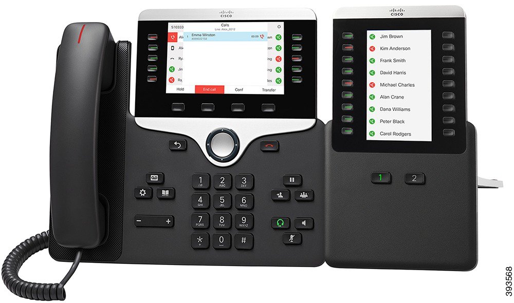
The Cisco IP Phone 8800 Key Expansion Module adds extra programmable buttons to the phone. The programmable buttons can be set up as phone line buttons, speed-dial buttons, or phone feature buttons
The following table lists the phones and the number of key expansion modules that each model supports.
|
Cisco IP Phone Model |
Supported Key Expansion Modules |
|---|---|
|
Cisco IP Phone 8851 |
2; providing 72 lines or buttons |
|
Cisco IP Phone 8861 |
3; providing 108 lines or buttons |
Key Expansion Module Power Information
If you use a key expansion module with your phone then Power over Ethernet (PoE) is enough to power your expansion modules. But a power cube is needed for smartphone or tablet charging when your expansion module is attached.
A key expansion module uses 48V DC, 5W per module. If you are charging a smartphone or a tablet, note the following:
|
Configuration |
802.3af Power over Ethernet (PoE) |
802.3at PoE |
Cisco IP Phone Power Cube 4 |
|---|---|---|---|
|
8851 with 1 expansion module |
Yes |
Yes |
Yes |
|
8851with 2 expansion modules |
No |
No See the third note above |
Yes |
|
8861 with 1 expansion module |
No |
Yes |
Yes |
|
8861 with 2 expansion modules |
No |
Yes See the first note above |
Yes |
|
8861 with 3 expansion modules |
No |
Yes See the first note above |
Yes |

Connect a Key Expansion Module to a Cisco IP Phone
Connect Two or Three Key Expansion Modules to a Cisco IP Phone
| Step 1 | Unplug the Ethernet cable from the phone. | ||
| Step 2 | If installed, remove the footstand from the phone. | ||
| Step 3 | Locate the accessory connector covers on the side of the phone. This diagram shows the location.  | ||
| Step 4 | Remove the two accessory connector covers, as shown in the diagram. 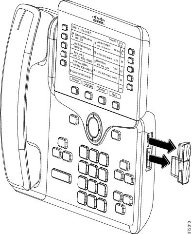
| ||
| Step 5 | Position the phone so that the front of the phone faces up. | ||
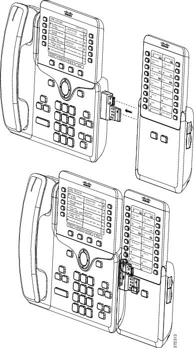
| Step 6 | Connect one end of the key expansion module spine connector to the accessory connector on the Cisco IP Phone. This diagram shows the spine connector. 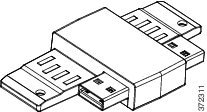 This diagram shows the installation of the spine connector. 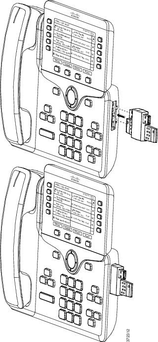 | ||
| Step 7 | Connect the other end of the spine connector to the key expansion module as shown in this diagram.
The first key expansion module is now connected to the Cisco IP Phone. | ||
| Step 8 | Use a second key expansion module spine connector to connect the second key expansion module to the first key expansion module. | ||
| Step 9 | Use a third key expansion module spine connector to connect the third key expansion module to the second (middle) key expansion module. This figure shows a Cisco IP Phone with three key expansion modules attached. 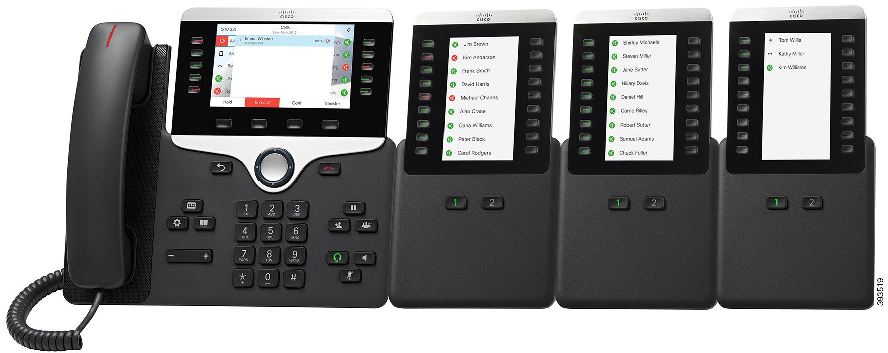 | ||
| Step 10 | Use a screwdriver to fasten the screws into the phone and into each key expansion module. This step ensures that the phone and key expansion modules remain connected at all times. This diagram shows the location of the screw holes. 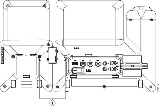
| ||
| Step 11 | (Optional) Install the footstands on the phone and on the key expansion modules, and adjust all footstands to rest evenly on the work surface. | ||
| Step 12 | Plug the Ethernet cable into the phone. |
Auto Detection of Key Expansion Modules
You can configure a new phone to auto-detect the maximum number of key expansion modules that it supports. For these phones, the Number of Units field shows the maximum number of key expansion modules that the phone supports as the default value. When a user adds key expansion modules to these phones, the module lights up and is enabled automatically. Default value of this field is 2 for Cisco IP Phone 8851 and 3 for Cisco IP Phone 8861. Navigate to to check the value of the Number of Units field.
If your user has an older release phone and it is upgraded to the current release, you can change the cofiguration of the phone so that when the user adds a key expansion module to the phone, it lights up and is enabled automatically.
Configure the Key Expansion Module from the Phone Web Page
You can set up your Key Expansion Module from the phone web page.
Access Key Expansion Module Setup
After you install one or more key expansion modules on the phone and configure them in the Configuration Utility page, the phone automatically recognizes the key expansion modules.
When multiple key expansion modules are attached, they are numbered according to the order in which they connect to the phone:
Key expansion module 1 is the expansion module closest to the phone.
Key expansion module 2 is the expansion module in the middle.
Key expansion module 3 is the expansion module farthest to the right.
When the phone automatically recognizes the key expansion modules, you can then choose the Show Details softkey for additional information about the selected key expansion module.
Reset the Single LCD Screen Key Expansion Module
If you are having technical difficulties with your Cisco IP Phone 8800 Key Expansion Module, you can reset the module to the factory default settings.
| Step 1 | Restart the expansion module by disconnecting the power source, waiting a few seconds, and then reconnecting it. |
| Step 2 | As the expansion module powers up, press and hold Page 1. As the LCD screen turns white, continue pressing Page 1 for at least one second. |
| Step 3 | Release Page 1. The LEDs turn red. |
| Step 4 | Immediately press Page 2 and continue pressing Page 2 for at least one second. |
| Step 5 | Release Page 2. The LEDs turn amber. |
| Step 6 | Press Lines 5, 14, 1, 18, 10, and 9 in sequence.
The LCD screen turns blue. A spinning icon is displayed in the center of the screen. The key expansion module resets. |
 Feedback