Wall Mounts
Wall Mount Options
-
Cisco IP Phone 8800 Series Wall Mount Kit: A nonlockable wall mount kit available for the Cisco IP Phone 8800 Series. This wall kit applies to Cisco IP Phone 8811, 8841, 8851, and 8861. The PID is CP-8800-WMK=.
-
Cisco IP Phone 8800 Series Wall Mount Kit with Single KEM: The kit is installed on the Cisco IP Phone 8851, and 8861 with one attached Cisco IP Phone 8800 Key Expansion Module. The PID is CP-8800-BEKEM-WMK=
Non-Lockable Wall Mount Components
This section describes how to install the Cisco IP Phone 8800 Series Wall Mount Kit.
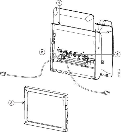
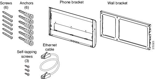
The following figure shows the components of the Cisco IP Phone 8800 Series Wall Mount Kit.
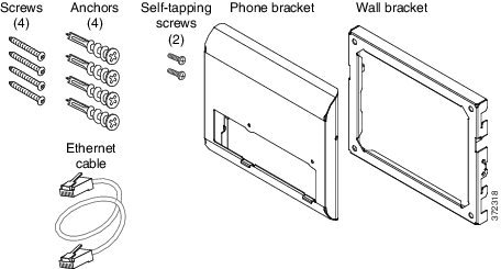
The package contains the following items:
One phone bracket
One wall bracket
Four #8-18 x 1.25-inch Phillips-head screws with four anchors
Two K30x8mm self-tapping screws
One 6-inch Ethernet cable
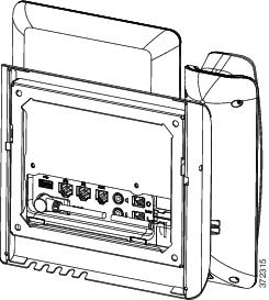
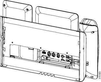
The following figure shows the wall mount kit installed on the phone.
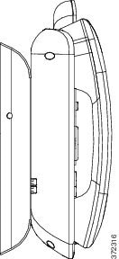
The following figure shows the phone with the wall mount kit from the side.
Install the Non-Lockable Wall Mount Kit for Phone
The wall mount kit can be mounted on most surfaces, including concrete, brick, and similar hard surfaces. To mount the kit on concrete, brick, or similar hard surfaces, you must provide the appropriate screws and anchors for your wall surface.
You need these tools to install the bracket:
You must also install an Ethernet jack for the telephone in the desired location if an Ethernet jack does not currently exist. This jack must be wired appropriately for an Ethernet connection. You cannot use a regular telephone jack.
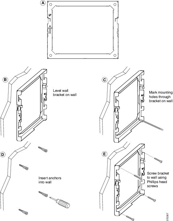
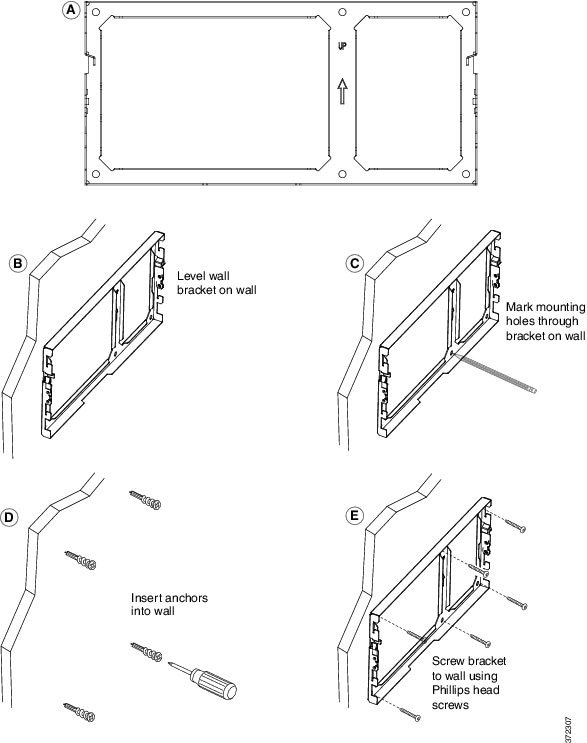
| Step 1 | Mount the wall
bracket in the desired location. You can install the bracket over an Ethernet
jack, or you can run the Ethernet network cable to a nearby jack.
 | ||
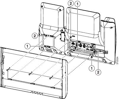
| Step 2 | Attach the phone bracket to the IP Phone. | ||
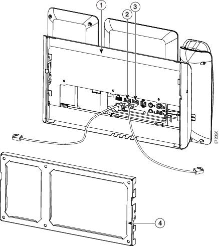
| Step 3 | Attach the
cables to the phone:
 | ||
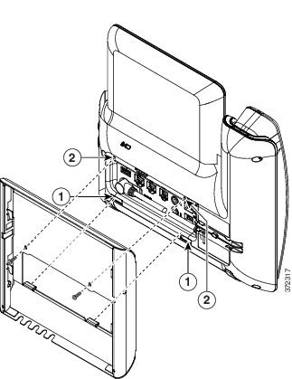
| Step 4 | Attach the
phone to the wall bracket by inserting the tabs on the top of the wall bracket
into the slots on the phone bracket.
For cables that terminate outside of the brackets, use the cable-access openings in the bottom of the bracket to position the power cord and any other cable that does not terminate in the wall behind the bracket. The phone and wall bracket openings together form circular openings with room for one cable per opening. 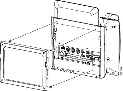 | ||
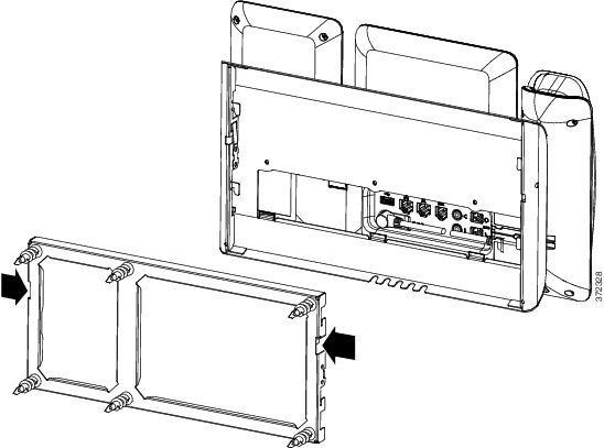
| Step 5 | Press the phone firmly into the wall bracket and slide the phone down. The tabs in the bracket click into position. | ||
| Step 6 | Proceed to Adjust the Handset Rest. |
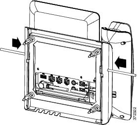
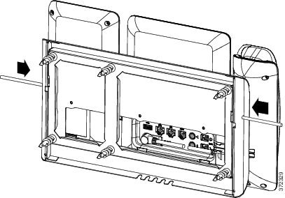
Remove the Phone from the Non-Lockable Wall Mount
The wall bracket has two tabs that lock the kit together. Use the following illustration to locate the tabs.
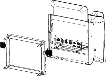
Obtain two Phillips head screwdrivers or other similar devices that have a diameter of 5 millimeters or 3/16ths of an inch.
Non-Lockable Wall Mount Components for Phone with Key Expansion Module
This section describes how to install the Cisco IP Phone 8800 Series Wall Mount Kit with Single KEM on a phone when the phone is connected to a Key Expansion Module.
The following figure shows the wall mount kit installed on the phone.
The following figure shows the phone with the wall mount kit from the side.
The following figure shows the components of the Cisco IP Phone 8800 Series Wall Mount Kit with Single KEM.
The package contains the following items:
- Install Non-Lockable Wall Mount Kit for Phone with Key Expansion Module
- Remove the Phone and Key Expansion Module from the Non-Lockable Wall Mount
Install Non-Lockable Wall Mount Kit for Phone with Key Expansion Module
The wall mount kit can be mounted on most surfaces, including concrete, brick, and similar hard surfaces. To mount the kit on concrete, brick, or similar hard surfaces, you must provide the appropriate screws and anchors for your wall surface.
You need these tools to install the bracket:
You must also install an Ethernet jack for the telephone in the desired location if an Ethernet jack does not currently exist. This jack must be wired appropriately for an Ethernet connection. You cannot use a regular telephone jack.
| Step 1 | Mount the wall bracket in the desired location. You can install the bracket over an Ethernet jack, or you can run the Ethernet network cable to a nearby jack.
 | ||
| Step 2 | Attach the phone bracket to the IP phone and key expansion assembly.
 | ||
| Step 3 | Attach the cords.
 | ||
| Step 4 | Attach the phone to the wall bracket by inserting the tabs on the top of the phone bracket into the slots on the wall bracket. For cables that terminate outside of the bracket, use the cable-access openings in the bottom of the bracket to position the power cord and any other cable that does not terminate in the wall behind the bracket. The phone and wall bracket openings together form circular openings with room for one cable per opening. 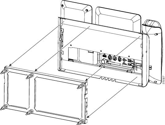 | ||
| Step 5 | Proceed to Adjust the Handset Rest. |
Remove the Phone and Key Expansion Module from the Non-Lockable Wall Mount
The wall bracket has two tabs that lock the kit together. Use the following illustration to locate the tabs.
Obtain two Phillips head screwdrivers or other similar devices that have a diameter of 5 millimeters or 3/16ths of an inch.
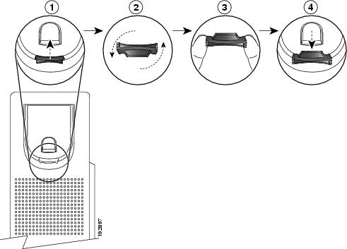
Adjust the Handset Rest
If your phone is wall-mounted or if the handset slips out of the cradle too easily, you may need to adjust the handset rest to ensure that the receiver does not slip out of the cradle.
 Feedback