DMP Specifications
- Environmental Conditions
- Site-Specific Conditions
- DMP Physical Specifications and Interfaces (I/O Ports)
- Internal LEDs
|
|
|
|
|---|---|---|
Environmental Conditions
Table 2-1 describes the temperature, humidity, and altitude ranges that a DMP can tolerate.
Site-Specific Conditions
Assess each location where you might want to use this equipment.
|
|
Install and use this equipment indoors — or outdoors in a covered area. |
|
|
There are — at most — only two supported methods to power this equipment.
|
|
|
Each new DMP (and each DMP on which you restore factory-default settings) uses DHCP to obtain its first IP address. Therefore, a DHCP server must be reachable from the site where you set up a DMP. Later, after your DMP is fully configured, it can use either static or dynamic IP addressing. |
|
|
When physical cables are too long, the signals that they carry can degrade. Signal loss can also affect wireless connections — including the infrared connection between a DMP and its remote control. When signal integrity suffers, equipment performance suffers. |
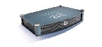
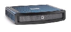
DMP Physical Specifications and Interfaces (I/O Ports)
Table 2 describes the connectors, sensors, and buttons on each DMP model.


|
|
|
|
|
|
||
|---|---|---|---|---|---|---|
|
Electrical Power |
||||||
PoE1 |
||||||
|
Network Connectivity |
||||||
| Wired2 |
||||||
Gigabit Ethernet3 |
||||||
Wireless4 |
||||||
|
Debugging (for Cisco use only) |
||||||
|
Media Signal |
||||||
| Wired5 |
||||||
HDMI 1.36 |
||||||
| Component7 |
||||||
Composite8 |
09 |
|||||
3.5mm jack10 |
||||||
|
Infrared |
||||||
Sensor for remote control11 |
||||||
|
Serial (Comm Ports) |
||||||
USB 2.012 |
||||||
|
Human |
||||||
|
1.IEEE 802.3af interface with integrated switching regulator. 5.For maximum supported media signal cable lengths, see the “Choose Suitable Media Signal Cables” section. Each video and audio signal cable that we ship with DMPs is 6 ft (approximately 1.83 m) long. 7.Use an S-Video signal cable with a YPbPr-to-S-Video adapter to transmit and receive YPbPr data signals. 8.When image signals are transmitted through a composite cable, image quality suffers. When you use a composite cable and your DMP shows any web-based media, small text might be difficult to read in TVzilla. To work around this limitation, you can lower the browser resolution setting in DMPDM.. 9.Although there is no Composite CVBS connector on a DMP 4310G, its YPbPr/S-Video connector supports Composite CVBS when you use an S-Video-to-Composite adapter. 10.Stereo audio output, irrespective of the cable type for video output. 11.Maximum distance from remote control to DMP is 15 ft (5 m). |
Power Cord Options


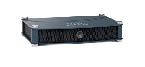
Internal LEDs
The DMP chassis contains a green LED and a red LED. After your DMP is attached to its AC power source, you should see light from both LEDs through the DMP front grille. The LEDs tell you when your DMP has power and when it has an IP address. To work as designed, it must have both.

 Feedback