- Preface
- Overview of Cisco Unified Computing System
- Overview of Cisco UCS Manager
- Overview of Cisco UCS Manager CLI
- Configuring the Fabric Interconnects
- Configuring Ports and Port Channels
- Configuring Communication Services
- Configuring Authentication
- Configuring Organizations
- Configuring Role-Based Access Control
- Configuring DNS Servers
- Configuring System-Related Policies
- Managing Licenses
- Managing Virtual Interfaces
- Registering Cisco UCS Domains with Cisco UCS Central
- VLANs
- Configuring LAN Pin Groups
- Configuring MAC Pools
- Configuring Quality of Service
- Configuring Network-Related Policies
- Configuring Upstream Disjoint Layer-2 Networks
- Configuring Named VSANs
- Configuring SAN Pin Groups
- Configuring WWN Pools
- Configuring Storage-Related Policies
- Configuring Fibre Channel Zoning
- Configuring Server-Related Pools
- Setting the Management IP Address
- Configuring Server-Related Policies
- Configuring Server Boot
- Deferring Deployment of Service Profile Updates
- Service Profiles
- Configuring Storage Profiles
- Managing Power in Cisco UCS
- Managing Time Zones
- Managing the Chassis
- Managing Blade Servers
- Managing Rack-Mount Servers
- CIMC Session Management
- Managing the I/O Modules
- Backing Up and Restoring the Configuration
- Recovering a Lost Password
- Server and Uplink Ports on the 6100 Series Fabric Interconnect
- Unified Ports on the Fabric Interconnect
- Port Modes
- Port Types
- Beacon LEDs for Unified Ports
- Guidelines for Configuring Unified Ports
- Cautions and Guidelines for Configuring Unified Uplink Ports and Unified Storage Ports
- Effect of Port Mode Changes on Data Traffic
- FC Links Rebalancing
- Configuring the Port Mode
- Configuring the Beacon LEDs for Unified Ports
- Physical and Backplane Ports
- Server Ports
- Uplink Ethernet Ports
- Appliance Ports
- FCoE Uplink Ports
- Unified Storage Ports
- Unified Uplink Ports
- FCoE and Fibre Channel Storage Ports
- Uplink Ethernet Port Channels
- Appliance Port Channels
- Fibre Channel Port Channels
- Configuring a Fibre Channel Port Channel
- Unconfiguring a Fibre Channel Port Channel
- Adding Channel Mode Active To The Upstream NPIV Fibre Channel Port Channel
- Enabling or Disabling a Fibre Channel Port Channel
- Adding a Member Port to a Fibre Channel Port Channel
- Deleting a Member Port from a Fibre Channel Port Channel
- FCoE Port Channels
- Unified Uplink Port Channel
- Event Detection and Action
- Adapter Port Channels
- Fabric Port Channels
Configuring Ports and Port Channels
This chapter includes the following sections:
- Server and Uplink Ports on the 6100 Series Fabric Interconnect
- Unified Ports on the Fabric Interconnect
- Physical and Backplane Ports
- Server Ports
- Uplink Ethernet Ports
- Appliance Ports
- FCoE Uplink Ports
- Unified Storage Ports
- Unified Uplink Ports
- FCoE and Fibre Channel Storage Ports
- Uplink Ethernet Port Channels
- Appliance Port Channels
- Fibre Channel Port Channels
- FCoE Port Channels
- Unified Uplink Port Channel
- Event Detection and Action
- Adapter Port Channels
- Fabric Port Channels
Server and Uplink Ports on the 6100 Series Fabric Interconnect
Each Cisco UCS 6100 Series Fabric Interconnect has a set of ports in a fixed port module that you can configure as either server ports or uplink Ethernet ports. These ports are not reserved. They cannot be used by a Cisco UCS domain until you configure them. You can add expansion modules to increase the number of uplink ports on the fabric interconnect or to add uplink Fibre Channel ports to the fabric interconnect.
 Note | When you configure a port on a fabric interconnect, the administrative state is automatically set to enabled. If the port is connected to another device, this may cause traffic disruption. You can disable the port after configuring it. |
You need to create LAN pin groups and SAN pin groups to pin traffic from servers to an uplink port.
Note | Ports on the Cisco UCS 6100 Series Fabric Interconnect are not unified. For more information on Unified Ports, see Unified Ports. |
Each fabric interconnect can include the following port types:
- Server Ports
-
Server ports handle data traffic between the fabric interconnect and the adapter cards on the servers.
You can only configure server ports on the fixed port module. Expansion modules do not include server ports.
- Uplink Ethernet Ports
-
Uplink Ethernet ports handle Ethernet traffic between the fabric interconnect and the next layer of the network. All network-bound Ethernet traffic is pinned to one of these ports.
By default, Ethernet ports are unconfigured. However, you can configure them to function in the following ways: You can configure uplink Ethernet ports on either the fixed module or an expansion module.
- Uplink Fibre Channel Ports
-
Uplink Fibre Channel ports handle FCoE traffic between the fabric interconnect and the next layer of the storage area network. All network-bound FCoE traffic is pinned to one of these ports.
By default, Fibre Channel ports are uplink. However, you can configure them to function as Fibre Channel storage ports. This is useful in cases where Cisco UCS requires a connection to a Direct-Attached Storage (DAS) device.
You can only configure uplink Fibre Channel ports on an expansion module. The fixed module does not include uplink Fibre Channel ports.
Unified Ports on the Fabric Interconnect
Unified ports are ports on the fabric interconnect that can be configured to carry either Ethernet or Fibre Channel traffic. These ports are not reserved. A Cisco UCS domain cannot use these ports until you configure them.
Note | When you configure a port on a fabric interconnect, the administrative state is automatically set to enabled. If the port is connected to another device, this may cause traffic disruption. You can disable the port after configuring it. |
Configurable beacon LEDs indicate which unified ports are configured for the selected port mode.
- Port Modes
- Port Types
- Beacon LEDs for Unified Ports
- Guidelines for Configuring Unified Ports
- Cautions and Guidelines for Configuring Unified Uplink Ports and Unified Storage Ports
- Effect of Port Mode Changes on Data Traffic
- FC Links Rebalancing
- Configuring the Port Mode
- Configuring the Beacon LEDs for Unified Ports
Port Modes
The port mode determines whether a unified port on the fabric interconnect is configured to carry Ethernet or Fibre Channel traffic. You configure the port mode in Cisco UCS Manager. However, the fabric interconnect does not automatically discover the port mode.
Changing the port mode deletes the existing port configuration and replaces it with a new logical port. Any objects associated with that port configuration, such as VLANs and VSANS, are also removed. There is no restriction on the number of times you can change the port mode for a unified port.
Port Types
The port type defines the type of traffic carried over a unified port connection.
By default, unified ports changed to Ethernet port mode are set to the Ethernet uplink port type. Unified ports changed to Fibre Channel port mode are set to the Fibre Channel uplink port type. You cannot unconfigure Fibre Channel ports.
Changing the port type does not require a reboot.
Ethernet Port Mode
When you set the port mode to Ethernet, you can configure the following port types:
-
Server ports
-
Ethernet uplink ports
-
Ethernet port channel members
-
FCoE ports
-
Appliance ports
-
Appliance port channel members
-
SPAN destination ports
-
SPAN source ports
Note
For SPAN source ports, configure one of the port types and then configure the port as SPAN source.
Fibre Channel Port Mode
When you set the port mode to Fibre Channel, you can configure the following port types:
Beacon LEDs for Unified Ports
Each port on the 6200 series fabric interconnect has a corresponding beacon LED. When the Beacon LED property is configured, the beacon LEDs illuminate, showing you which ports are configured in a given port mode.
You can configure the Beacon LED property to show you which ports are grouped in one port mode: either Ethernet or Fibre Channel. By default, the Beacon LED property is set to Off.
Note | For unified ports on the expansion module, you can reset the Beacon LED property to the default value of Off during expansion module reboot. |
Guidelines for Configuring Unified Ports
Consider the following guidelines and restrictions when configuring unified ports:
Hardware and Software Requirements
Unified ports are supported on the 6200 series fabric interconnect with Cisco UCS Manager, version 2.0.
Unified ports are not supported on 6100 series fabric interconnects, even if they are running Cisco UCS Manager, version 2.0.
Port Mode Placement
Because the Cisco UCS Manager GUI interface uses a slider to configure the port mode for unified ports on a fixed or expansion module, it automatically enforces the following restrictions which limits how port modes can be assigned to unified ports. When using the Cisco UCS Manager CLI interface, these restrictions are enforced when you commit the transaction to the system configuration. If the port mode configuration violates any of the following restrictions, the Cisco UCS Manager CLI displays an error:
-
Ethernet ports must be grouped together in a block. For each module (fixed or expansion), the Ethernet port block must start with the first port and end with an even numbered port.
-
Fibre Channel ports must be grouped together in a block. For each module (fixed or expansion), the first port in the Fibre Channel port block must follow the last Ethernet port and extend to include the rest of the ports in the module. For configurations that include only Fibre Channel ports, the Fibre Channel block must start with the first port on the fixed or expansion module.
-
Alternating Ethernet and Fibre Channel ports is not supported on a single module.
Example of a valid configuration— Might include unified ports 1–16 on the fixed module configured in Ethernet port mode and ports 17–32 in Fibre Channel port mode. On the expansion module you could configure ports 1–4 in Ethernet port mode and then configure ports 5–16 in Fibre Channel mode. The rule about alternating Ethernet and Fibre Channel port types is not violated because this port arrangement complies with the rules on each individual module.
Example of an invalid configuration— Might include a block of Fibre Channel ports starting with port 16. Because each block of ports has to start with an odd-numbered port, you would have to start the block with port 17.
Note | The total number of uplink Ethernet ports and uplink Ethernet port channel members that can be configured on each fabric interconnect is limited to 31. This limitation includes uplink Ethernet ports and uplink Ethernet port channel members configured on the expansion module. |
Special Considerations for UCS Manager CLI Users
Because the Cisco UCS Manager CLI does not validate port mode changes until you commit the buffer to the system configuration, it is easy to violate the grouping restrictions if you attempt to commit the buffer before creating at least two new interfaces. To prevent errors, we recommend that you wait to commit your changes to the system configuration until you have created new interfaces for all of the unified ports changing from one port mode to another.
Commiting the buffer before configuring multiple interfaces will result in an error, but you do not need to start over. You can continue to configure unified ports until the configuration satisfies the aforementioned requirements.
Cautions and Guidelines for Configuring Unified Uplink Ports and Unified Storage Ports
The following are cautions and guidelines to follow while working with unified uplink ports and unified storage ports:
-
In an unified uplink port, if you enable one component as a SPAN source, the other component will automatically become a SPAN source.
Note
If you create or delete a SPAN source under the Ethernet uplink port, Cisco UCS Manager automatically creates or deletes a SPAN source under the FCoE uplink port. The same happens when you create a SPAN source on the FCOE uplink port.
-
You must configure a non default native VLAN on FCoE and unified uplink ports. This VLAN is not used for any traffic. Cisco UCS Manager will reuse an existing fcoe-storage-native-vlan for this purpose. This fcoe-storage-native-vlan will be used as a native VLAN on FCoE and unified uplinks.
-
In an unified uplink port, if you do not specify a non default VLAN for the Ethernet uplink port the fcoe-storage-native-vlan will be assigned as the native VLAN on the unified uplink port. If the Ethernet port has a non default native VLAN specified as native VLAN, this will be assigned as the native VLAN for unified uplink port.
-
When you create or delete a member port under an Ethernet port channel, Cisco UCS Manager automatically creates or deletes the member port under FCoE port channel. The same happens when you create or delete a member port in FCoE port channel.
-
When you configure an Ethernet port as a standalone port, such as server port, Ethernet uplink, FCoE uplink or FCoE storage and make it as a member port for an Ethernet or FCOE port channel, Cisco UCS Manager automatically makes this port as a member of both Ethernet and FCoE port channels.
-
When you remove the membership for a member port from being a member of server uplink, Ethernet uplink, FCoE uplink or FCoE storage, Cisco UCS Manager deletes the corresponding members ports from Ethernet port channel and FCoE port channel and creates a new standalone port.
-
If you downgrade Cisco UCS Manager from release 2.1 to any of the prior releases, all unified uplink ports and port channels will be converted to Ethernet ports and Ethernet port channels when the downgrade is complete. Similarly, all the unified storage ports will be converted to appliance ports.
-
For unified uplink ports and unified storage ports, when you create two interfaces, only one license is checked out. As long as either interface is enabled, the license remains checked out. The license will be released only if both the interfaces are disabled for a unified uplink port or a unified storage port.
-
Cisco UCS 6100 series fabric interconnect switch can only support 1VF or 1VF-PO facing same downstream NPV switch.
Effect of Port Mode Changes on Data Traffic
Port mode changes can cause an interruption to the data traffic for the Cisco UCS domain. The length of the interruption and the traffic that is affected depend upon the configuration of the Cisco UCS domain and the module on which you made the port mode changes.
 Tip | To minimize the traffic disruption during system changes, form a Fibre Channel uplink port-channel across the fixed and expansion modules. |
Impact of Port Mode Changes on an Expansion Module
After you make port mode changes on an expansion module, the module reboots. All traffic through ports on the expansion module is interrupted for approximately one minute while the module reboots.
Impact of Port Mode Changes on the Fixed Module in a Cluster Configuration
A cluster configuration has two fabric interconnects. After you make port changes to the fixed module, the fabric interconnect reboots. The impact on the data traffic depends upon whether or not you have configured the server vNICs to failover to the other fabric interconnect when one fails.
If you change the port modes on the expansion module of one fabric interconnect and then wait for that to reboot before changing the port modes on the second fabric interconnect, the following occurs:
-
With server vNIC failover, traffic fails over to the other fabric interconnect and no interruption occurs.
-
Without server vNIC failover, all data traffic through the fabric interconnect on which you changed the port modes is interrupted for approximately eight minutes while the fabric interconnect reboots.
If you change the port modes on the fixed modules of both fabric interconnects simultaneously, all data traffic through the fabric interconnects are interrupted for approximately eight minutes while the fabric interconnects reboot.
Impact of Port Mode Changes on the Fixed Module in a Standalone Configuration
A standalone configuration has only one fabric interconnect. After you make port changes to the fixed module, the fabric interconnect reboots. All data traffic through the fabric interconnect is interrupted for approximately eight minutes while the fabric interconnect reboots.
FC Links Rebalancing
The FC uplinks balance automatically when FC Port Channels are utilized. To create FC Port Channels, refer to Configuring a Fibre Channel Port Channel.
For the FC uplinks that are not members of the Port Channels (Individual ISLs), load balancing is done according to the FC uplinks balancing algorithm. For a vHBA of a host or service profile to choose an available FC uplink, when FC uplink trunking is disabled, the uplink and vHBA must belong to the same VSAN
This process continues for all the other vHBAs. The algorithm also considers other parameters such as pre-fip/fip adapters and number of flogis. You may not see the least-used component when there are less than six flogis.
After a port configuration or any other uplink state changes, if the traffic passing through the FC uplinks is no longer balanced, you can re-balance the traffic by resetting the vHBA(s) on each adapter and allow the load balancing algorithm to evaluate for the current state of the FC uplinks.
Configuring the Port Mode
 Caution | Changing the port mode on either module can cause an interruption in data traffic because changes to the fixed module require a reboot of the fabric interconnect and changes on an expansion module require a reboot of that module . If the Cisco UCS domain has a cluster configuration that is set up for high availability and servers with service profiles that are configured for failover, traffic fails over to the other fabric interconnect and data traffic is not interrupted when the port mode is changed on the fixed module. |
In the Cisco UCS Manager CLI, there are no new commands to support Unified Ports. Instead, you change the port mode by scoping to the mode for the desired port type and then creating a new interface. When you create a new interface for an already configured slot ID and port ID, UCS Manager deletes the previously configured interface and creates a new one. If a port mode change is required because you configure a port that previously operated in Ethernet port mode to a port type in Fibre Channel port mode, UCS Manager notes the change.
| Command or Action | Purpose | |
|---|---|---|
| Step 1 |
UCS-A#
scope
port-type-mode
|
Enters the specified port type mode for one of the following port types:
|
| Step 2 | UCS-A /port-type-mode # scope fabric {a | b} |
Enters the specified port type mode for the specified fabric. |
| Step 3 | UCS-A /port-type-mode/fabric # create interface slot-id port-id |
Creates an interface for the specified port type. If you are changing the port type from Ethernet port mode to Fibre Channel port mode, or vice-versa, the following warning appears: Warning: This operation will change the port mode (from Ethernet to FC or vice-versa). When committed, this change will require the module to restart. |
| Step 4 | Create new interfaces for other ports belonging to the Ethernet or Fibre Channel port block. |
There are several restrictions that govern how Ethernet and Fibre Channel ports can be arranged on a fixed or expansion module. Among other restrictions, it is required that you change ports in groups of two. Violating any of the restrictions outlined in the Guidelines and Recommendations for Configuring Unified Ports section will result in an error. |
| Step 5 | UCS-A /port-type-mode/fabric/interface # commit-buffer |
Commits the transaction to the system configuration. |
Based on the module for which you configured the port modes, data traffic for the Cisco UCS domain is interrupted as follows:
-
Fixed module—The fabric interconnect reboots. All data traffic through that fabric interconnect is interrupted. In a cluster configuration that provides high availability and includes servers with vNICs that are configured for failover, traffic fails over to the other fabric interconnect and no interruption occurs. Changing the port mode for both sides at once results in both fabric interconnects rebooting simultaneously and a complete loss of traffic until both fabric interconnects are brought back up.
It takes about 8 minutes for the fixed module to reboot.
-
Expansion module—The module reboots. All data traffic through ports in that module is interrupted.
It takes about 1 minute for the expansion module to reboot.
The following example changes ports 3 and 4 on slot 1 from Ethernet uplink ports in Ethernet port mode to uplink Fibre Channel ports in Fibre Channel port mode:
UCS-A# scope fc-uplink
UCS-A /fc-uplink # scope fabric a
UCS-A /fc-uplink/fabric # create interface 1 3
Warning: This operation will change the port mode (from Ethernet to FC or vice-versa).
When committed, this change will require the fixed module to restart.
UCS-A /fc-uplink/fabric/interface* # up
UCS-A /fc-uplink/fabric* #create interface 1 4
Warning: This operation will change the port mode (from Ethernet to FC or vice-versa).
When committed, this change will require the fixed module to restart.
UCS-A /fc-uplink/fabric/interface* #commit-buffer
Configuring the Beacon LEDs for Unified Ports
Complete the following task for each module for which you want to configure beacon LEDs.
The following example illuminates all of the beacon lights for Unified Ports in Ethernet port mode and commits the transaction:
UCS-A# scope fabric-interconnect a
UCS-A /fabric # scope card 1
UCS-A /fabric/card # scope beacon-led
UCS-A /fabric/card/beacon-led # set admin-state eth
UCS-A /fabric/card/beacon-led* # commit-buffer
UCS-A /fabric/card/beacon-led #
Physical and Backplane Ports
Displaying Physical Port Statistics Obtained From the ASIC
| Command or Action | Purpose |
|---|
The following example shows how to display physical port statistics that are obtained from the ASIC:
UCS-A /fabric-interconnect # connect nxos a
UCS-A(nxos)# show interface ethernet 1/11

Ethernet1/11 is up
 Dedicated Interface
  Hardware: 40000 Ethernet, address: a46c.2ae3.0e1a (bia a46c.2ae3.0e1a)
  Description: S: Server
  MTU 1500 bytes, BW 40000000 Kbit, DLY 10 usec
  reliability 255/255, txload 1/255, rxload 1/255
  Encapsulation ARPA
  Port mode is fex-fabric
  full-duplex, 40 Gb/s, media type is 40G
  Beacon is turned off
  Input flow-control is off, output flow-control is off
  Rate mode is dedicated
  Switchport monitor is off
  EtherType is 0x8100
  Last link flapped 01:25:42
  Last clearing of "show interface" counters never
  2 interface resets
  30 seconds input rate 22664 bits/sec, 2833 bytes/sec, 3 packets/sec
  30 seconds output rate 9512 bits/sec, 1189 bytes/sec, 1189 bytes/sec, 4 packets/sec
  Load-Interval #2: 5 minute (300 seconds)
    input rate 33.80 Kbps, 5 pps; output rate 1.23 Mbps, 71 pps
  RX
    126057 unicast packets  1744 multicast packets  12877 broadcast packets
    140693 input packets  28702696 bytes
    3351 jumbo packets  0 storm suppression bytes
    0 runts  0 giants  0 CRC  0 no buffer
    0 input error  0 short frame  0 overrun   0 underrun  0 ignored
    0 watchdog  0 bad etype drop  0 bad proto drop  0 if down drop
    0 input with dribble  184 input discard
    0 Rx pause
  TX
    919778 unicast packets  6991 multicast packets  29 broadcast packets
    926798 output packets  1237109219 bytes
    794275 jumbo packets
    0 output errors  0 collision  0 deferred  0 late collision
    0 lost carrier  0 no carrier  0 babble 0 output discard
    0 Tx pause

  Errors on Peer port (NIF):
  RX
    8300 toolong frames  8400 undersize frames  8500 fragment frames
    8600 crcErr_not_stomped frames  8700 crcErr_stomped frames  8800 inRangeErr frames
  TX
    8200 frames_with_error
Displaying Physical Ports on the Fabric Interconnect That Correspond to Physical Ports on BCM
| Command or Action | Purpose |
|---|
The following example shows how to display physical ports on a fabric interconnect that correspond to physical ports on BCM:
UCS-A /fabric-interconnect # connect nxos a
UCS-A(nxos)# show hardware internal bcm-usd info port-info | grep Eth 1/11

Eth1/11      0x1a00a000  41 xe-40   57   CR4 sw 4044 0 uta  2240     0 fd dis blk dis dis ena 40G 40G up
Verifying Status of Backplane Ports
| Command or Action | Purpose |
|---|
The following example shows how to verify the status of backplane ports for fabric interconnect A:
UCS-A /fabric-interconnect # connect nxos a
UCS-A(nxos)# show interface br


--------------------------------------------------------------------------------
Ethernet      VLAN   Type Mode   Status  Reason                   Speed     Port
Interface                                                                   Ch #
--------------------------------------------------------------------------------
Eth1/1        1       eth  access down    SFP not inserted            40G(D) --
Eth1/2        1       eth  access down    SFP not inserted            40G(D) --
Br-Eth1/3/1   1       eth  access down    Administratively down       10G(D) --
Br-Eth1/3/2   1       eth  access down    Administratively down       10G(D) --
Br-Eth1/3/3   1       eth  access down    Administratively down       10G(D) --
Br-Eth1/3/4   1       eth  access down    Administratively down       10G(D) --
Eth1/4        1       eth  access down    SFP not inserted            40G(D) --
Br-Eth1/5/1   4044    eth  trunk  down    Link not connected          10G(D) --
Br-Eth1/5/2   4044    eth  trunk  down    Link not connected          10G(D) --
Br-Eth1/5/3   4044    eth  trunk  down    Link not connected          10G(D) --
Br-Eth1/5/4   4044    eth  trunk  down    Link not connected          10G(D) --
Eth1/6        1       eth  access down    SFP not inserted            40G(D) --
Eth1/7        1       eth  access down    SFP not inserted            40G(D) --
Eth1/8        1       eth  access down    SFP not inserted            40G(D) --
Eth1/9        1       eth  access down    SFP not inserted            40G(D) --
Eth1/10       1       eth  access down    SFP not inserted            40G(D) --
Eth1/11       1       eth  fabric up      none                        40G(D) --
Eth1/12       1       eth  access down    SFP not inserted            40G(D) --
Eth1/13       1       eth  access down    SFP not inserted            40G(D) --
Eth1/14       1       eth  access down    SFP not inserted            40G(D) --
Eth1/15       1       eth  access down    SFP not inserted            40G(D) --
Eth1/16       1       eth  access down    SFP not inserted            40G(D) --
Eth1/17       1       eth  access down    SFP not inserted            40G(D) --
Eth1/18       1       eth  access down    SFP not inserted            40G(D) --
Eth1/19       1       eth  access down    SFP not inserted            40G(D) --
Eth1/20       1       eth  access down    SFP not inserted            40G(D) --
Br-Eth1/21/1  1       eth  trunk  up      none                        10G(D) --
Br-Eth1/21/2  1       eth  trunk  up      none                        10G(D) --
Br-Eth1/21/3  1       eth  trunk  down    Link not connected          10G(D) --
Br-Eth1/21/4  1       eth  trunk  up      none                        10G(D) --
Eth1/22       1       eth  access down    SFP not inserted            40G(D) --
Eth1/23       1       eth  access down    SFP not inserted            40G(D) --
Eth1/24       1       eth  access down    SFP not inserted            40G(D) --
Eth1/25       1       eth  access down    SFP not inserted            40G(D) --
Eth1/26       1       eth  access down    SFP not inserted            40G(D) --
Eth1/27       1       eth  access down    SFP not inserted            40G(D) --
Eth1/28       1       eth  access down    SFP not inserted            40G(D) --
Eth1/29       1       eth  access down    SFP not inserted            40G(D) --
Eth1/30       1       eth  access down    SFP not inserted            40G(D) --
Eth1/31       1       eth  access down    SFP not inserted            40G(D) --
Eth1/32       1       eth  access down    SFP not inserted            40G(D) --

--------------------------------------------------------------------------------
Port-channel VLAN    Type Mode   Status  Reason                    Speed   Protocol
Interface
--------------------------------------------------------------------------------
Po1285       1       eth  vntag  up      none                       a-10G(D)  none
Po1286       1       eth  vntag  up      none                       a-10G(D)  none
Po1287       1       eth  vntag  up      none                       a-10G(D)  none
Po1288       1       eth  vntag  up      none                       a-10G(D)  none
Po1289       1       eth  vntag  up      none                       a-10G(D)  none

--------------------------------------------------------------------------------
Port   VRF          Status IP Address                              Speed    MTU
--------------------------------------------------------------------------------
mgmt0  --           down   10.197.157.252                          --       1500

--------------------------------------------------------------------------------
Vethernet     VLAN   Type Mode   Status  Reason                    Speed
--------------------------------------------------------------------------------
Veth691       4047   virt trunk  down    nonParticipating         auto
Veth692       4047   virt trunk  up      none                     auto
Veth693       1      virt trunk  down    nonParticipating         auto
Veth695       1      virt trunk  up      none                     auto
Veth699       1      virt trunk  up      none                     auto

-------------------------------------------------------------------------------
Interface Secondary VLAN(Type)                    Status Reason
-------------------------------------------------------------------------------
Vlan1     --                                      down   Administratively down

--------------------------------------------------------------------------------
Ethernet       VLAN   Type Mode   Status  Reason                  Speed     Port
Interface                                                                   Ch #
--------------------------------------------------------------------------------
Eth1/1/1       1       eth  vntag  up      none                       10G(D) 1286
Eth1/1/2       1       eth  access down    Administratively down      10G(D) --
Eth1/1/3       1       eth  vntag  up      none                       10G(D) 1286
Eth1/1/4       1       eth  access down    Administratively down      10G(D) --
Eth1/1/5       1       eth  vntag  up      none                       10G(D) 1287
Eth1/1/6       1       eth  access down    Administratively down      10G(D) --
Eth1/1/7       1       eth  vntag  up      none                       10G(D) 1287
Eth1/1/8       1       eth  access down    Administratively down      10G(D) --
Eth1/1/9       1       eth  vntag  up      none                       10G(D) 1289
Eth1/1/10      1       eth  access down    Administratively down      10G(D) --
Eth1/1/11      1       eth  vntag  up      none                       10G(D) 1289
Eth1/1/12      1       eth  access down    Administratively down      10G(D) --
Eth1/1/13      1       eth  vntag  up      none                       10G(D) 1285
Eth1/1/14      1       eth  access down    Administratively down      10G(D) --
Eth1/1/15      1       eth  vntag  up      none                       10G(D) 1285
Eth1/1/16      1       eth  access down    Administratively down      10G(D) --
Eth1/1/17      1       eth  access down    Administratively down      10G(D) --
Eth1/1/18      1       eth  vntag  up      none                       10G(D) 1288
Eth1/1/19      1       eth  access down    Administratively down      10G(D) --
Eth1/1/20      1       eth  vntag  up      none                       10G(D) 1288
Eth1/1/21      1       eth  access down    Administratively down      10G(D) --
Eth1/1/22      1       eth  access down    Administratively down      10G(D) --
Eth1/1/23      1       eth  access down    Administratively down      10G(D) --
Eth1/1/24      1       eth  access down    Administratively down      10G(D) --
Eth1/1/25      1       eth  access down    Administratively down      10G(D) --
Eth1/1/26      1       eth  access down    Administratively down      10G(D) --
Eth1/1/27      1       eth  access down    Administratively down      10G(D) --
Eth1/1/28      1       eth  access down    Administratively down      10G(D) --
Eth1/1/29      1       eth  access down    Administratively down      10G(D) --
Eth1/1/30      1       eth  access down    Administratively down      10G(D) --
Eth1/1/31      1       eth  access down    Administratively down      10G(D) --
Eth1/1/32      1       eth  access down    Administratively down      10G(D) --
Eth1/1/33      4044    eth  trunk  up      none                      1000(D) --
Server Ports
Configuring a Server Port
All of the port types listed are configurable on both the fixed and expansion module, including server ports, which are not configurable on the 6100 series fabric interconnect expansion module, but are configurable on the 6200 series fabric interconnect expansion module.
The following example shows how to create an interface for Ethernet server port 4 on slot 1 of fabric B and commit the transaction:
UCS-A# scope eth-server
UCS-A /eth-server # scope fabric b
UCS-A /eth-server/fabric # create interface 1 4
UCS-A /eth-server/fabric* # commit-buffer
UCS-A /eth-server/fabric #
Unconfiguring a Server Port
The following example unconfigures Ethernet server port 12 on slot 1 of fabric B and commits the transaction:
UCS-A# scope eth-server
UCS-A /eth-server # scope fabric b
UCS-A /eth-server/fabric # delete interface 1 12
UCS-A /eth-server/fabric* # commit-buffer
UCS-A /eth-server/fabric #
Uplink Ethernet Ports
Configuring an Uplink Ethernet Port
You can configure uplink Ethernet ports on either the fixed module or an expansion module.
The following example shows how to create an interface for Ethernet uplink port 3 on slot 2 of fabric B, set the speed to 10 gbps, and commit the transaction:
UCS-A# scope eth-uplink
UCS-A /eth-uplink # scope fabric b
UCS-A /eth-uplink/fabric # create interface 2 3
UCS-A /eth-uplink/fabric # set speed 10gbps
UCS-A /eth-uplink/fabric* # commit-buffer
UCS-A /eth-uplink/fabric #
Unconfiguring an Uplink Ethernet Port
| Command or Action | Purpose | |
|---|---|---|
| Step 1 | UCS-A# scope eth-uplink |
Enters Ethernet uplink mode. |
| Step 2 | UCS-A /eth-uplink # scope fabric {a | b} |
Enters Ethernet uplink fabric mode for the specified fabric. |
| Step 3 | UCS-A /eth-uplink/fabric # delete interface slot-num port-num |
Deletes the interface for the specified Ethernet uplink port. |
| Step 4 | UCS-A /eth-uplink/fabric # commit-buffer |
Commits the transaction to the system configuration. |
The following example unconfigures Ethernet uplink port 3 on slot 2 of fabric B and commits the transaction:
UCS-A# scope eth-uplink
UCS-A /eth-uplink # scope fabric b
UCS-A /eth-uplink/fabric # delete interface 2 3
UCS-A /eth-uplink/fabric* # commit-buffer
UCS-A /eth-uplink/fabric #
Appliance Ports
Note | When you create a new appliance VLAN, its IEEE VLAN ID is not added to the LAN Cloud. Therefore, appliance ports that are configured with the new VLAN remain down, by default, due to a pinning failure. To bring up these appliance ports, you have to configure a VLAN in the LAN Cloud with the same IEEE VLAN ID. |
Cisco UCS Manager supports up to four appliance ports per fabric interconnect.
- Configuring an Appliance Port
- Assigning a Target MAC Address to an Appliance Port or Appliance Port Channel
- Creating an Appliance Port
- Mapping an Appliance Port to a Community VLAN
- Unconfiguring an Appliance Port
Configuring an Appliance Port
You can configure Appliance ports on either the fixed module or an expansion module.
| Command or Action | Purpose | |||
|---|---|---|---|---|
| Step 1 | UCS-A# scope eth-storage |
Enters Ethernet storage mode. | ||
| Step 2 | UCS-A /eth-storage # scope fabric{a | b} |
Enters Ethernet storage mode for the specified fabric. | ||
| Step 3 | UCS-A /eth-storage/fabric # create interface slot-num port-num |
Creates an interface for the specified appliance port. | ||
| Step 4 | UCS-A /eth-storage/fabric/interface # set portmode {access | trunk} | (Optional)
Specifies whether the port mode is access or trunk. By default, the mode is set to trunk.
| ||
| Step 5 | UCS-A /eth-storage/fabric/interface # set pingroupname pin-group name | (Optional)
Specifies the appliance pin target to the specified fabric and port, or fabric and port channel. | ||
| Step 6 | UCS-A /eth-storage/fabric/interface # set prio sys-class-name | (Optional)
Specifies the QoS class for the appliance port. By default, the priority is set to best-effort. The sys-class-name argument can be one of the following class keywords:
| ||
| Step 7 | UCS-A /eth-storage/fabric/interface # set adminspeed {10gbps | 1 gbps} | (Optional)
Specifies the admin speed for the interface. By default, the admin speed is set to 10gbps. | ||
| Step 8 | UCS-A /eth-storage/fabric/interface # commit buffer |
Commits the transaction to the system configuration. |
The following example creates an interface for an appliance port 2 on slot 3 of fabric B, sets the port mode to access, pins the appliance port to a pin group called pingroup1, sets the QoS class to fc, sets the admin speed to 10 gbps, and commits the transaction:
UCS-A# scope eth-storage
UCS-A /eth-storage # scope fabric b
UCS-A /eth-storage/fabric # create interface 3 2
UCS-A /eth-storage/fabric* # set portmode access
UCS-A /eth-storage/fabric* # set pingroupname pingroup1
UCS-A /eth-storage/fabric* # set prio fc
UCS-A /eth-storage/fabric* # set adminspeed 10gbps
UCS-A /eth-storage/fabric* # commit-buffer
UCS-A /eth-storage/fabric #
Assign a VLAN or target MAC address for the appliance port.
Assigning a Target MAC Address to an Appliance Port or Appliance Port Channel
The following procedure assigns a target MAC address to an appliance port. To assign a target MAC address to an appliance port channel, scope to the port channel instead of the interface.
| Command or Action | Purpose | |||
|---|---|---|---|---|
| Step 1 | UCS-A# scope eth-storage |
Enters Ethernet storage mode. | ||
| Step 2 | UCS-A /eth-storage # scope fabric{a | b} |
Enters Ethernet storage mode for the specified fabric. | ||
| Step 3 | UCS-A /eth-storage/fabric # scope interface slot-id port-id |
| ||
| Step 4 | UCS-A /eth-storage/fabric/interface # create eth-target eth-target name |
Specifies the name for the specified MAC address target. | ||
| Step 5 | UCS-A /eth-storage/fabric/interface/eth-target # set mac-address mac-address |
Specifies the MAC address in nn:nn:nn:nn:nn:nn format. |
The following example assigns a target MAC address for an appliance device on port 3, slot 2 of fabric B and commits the transaction:
UCS-A# scope eth-storage
UCS-A /eth-storage* # scope fabric b
UCS-A /eth-storage/fabric* # scope interface 2 3
UCS-A /eth-storage/fabric/interface* # create eth-target macname
UCS-A /eth-storage/fabric/interface* # set mac-address 01:23:45:67:89:ab
UCS-A /eth-storage/fabric/interface* # commit-buffer
UCS-A /eth-storage/fabric #
The following example assigns a target MAC address for appliance devices on port channel 13 of fabric B and commits the transaction:
UCS-A# scope eth-storage
UCS-A /eth-storage* # scope fabric b
UCS-A /eth-storage/fabric* # scope port-channel 13
UCS-A /eth-storage/fabric/port-channel* # create eth-target macname
UCS-A /eth-storage/fabric/port-channel* # set mac-address 01:23:45:67:89:ab
UCS-A /eth-storage/fabric/port-channel* # commit-buffer
UCS-A /eth-storage/fabric #
Creating an Appliance Port
| Command or Action | Purpose | |
|---|---|---|
| Step 1 | UCS-A# scope eth-storage |
Enters Ethernet storage mode. |
| Step 2 | UCS-A/eth-storage# create vlan vlan-name vlan-id |
Creates a named VLAN, specifies the VLAN name and VLAN ID, and enters Ethernet storage VLAN mode |
| Step 3 | UCS-A/eth-storage/vlan# set sharing primary |
Saves the changes. |
| Step 4 | UCS-A/eth-storage/vlan# commit buffer |
Commits the transaction to the system configuration. |
| Step 5 | UCS-A/eth-storage# create vlan vlan-name vlan-id |
Creates a named VLAN, specifies the VLAN name and VLAN ID, and enters Ethernet storage VLAN mode . |
| Step 6 | UCS-A/eth-storage/vlan# set sharing community |
Associates the primary VLAN to the secondary VLAN that you are creating. |
| Step 7 | UCS-A/eth-storage/vlan# set pubnwname primary vlan-name |
Specifies the primary VLAN to be associated with this secondary VLAN. |
| Step 8 | UCS-A/eth-storage/vlan# commit buffer |
Commits the transaction to the system configuration. |
The following example creates an appliance port:
UCS-A# scope eth-storage
UCS-A/eth-storage# create vlan PRI600 600
UCS-A/eth-storage/vlan* # set sharing primary
UCS-A/eth-storage/vlan* # commit-buffer
UCS-A/eth-storage # create vlan COM602 602
UCS-A/eth-storage/vlan* # set sharing isolated
UCS-A/eth-storage/vlan* # set pubnwname PRI600
UCS-A/eth-storage/vlan* # commit-buffer
Mapping an Appliance Port to a Community VLAN
| Command or Action | Purpose | |||
|---|---|---|---|---|
| Step 1 | UCS-A# scope eth-storage |
Enters Ethernet storage mode. | ||
| Step 2 | UCS-A/eth-storage# scope fabric {a|b} |
Enters Ethernet storage fabric interconnect mode for the specified fabric interconnect. | ||
| Step 3 | UCS-A/eth-storage/fabric# create interface slot-num port-num |
Creates an interface for the specified Ethernet server port. | ||
| Step 4 | UCS-A/eth-storage/fabric/interface# exit |
Exits from the interface.
| ||
| Step 5 | UCS-A/eth-storage/fabric# exit |
Exits from the fabric. | ||
| Step 6 | UCS-A/eth-storage# scope vlan vlan-name |
Enters the specified VLAN.
| ||
| Step 7 | UCS-A/eth-storage/vlan# create member-port fabric slot-num port-num |
Creates the member port for the specified fabric, assigns the slot number, and port number and enters member port configuration. | ||
| Step 8 | UCS-A/eth-storage/vlan/member-port# commit |
Commits the transaction to the system configuration. |
The following example maps an appliance port to an community VLAN:
UCS-A# scope eth-storage
UCS-A/eth-storage# scope fabric a
UCS-A/eth-storage/fabric# create interface 1 22
UCS-A/eth-storage/fabric/interface*# exit
UCS-A/eth-storage/fabric*# exit
UCS-A/eth-storage*# scope vlan COM602
UCS-A/eth-storage/vlan*# create member-port a 1 22
UCS-A/eth-storage/vlan/member-port* commit
Unconfiguring an Appliance Port
| Command or Action | Purpose | |
|---|---|---|
| Step 1 | UCS-A # scope eth-storage |
Enters Ethernet storage mode. |
| Step 2 | UCS-A /eth-storage # scope fabric {a | b} |
Enters Ethernet storage mode for the specified fabric. |
| Step 3 | UCS-A /eth-storage/fabric # delete eth-interface slot-num port-num |
Deletes the interface for the specified appliance port. |
| Step 4 | UCS-A /eth-storage/fabric # commit-buffer |
Commits the transaction to the system configuration. |
The following example unconfigures appliance port 3 on slot 2 of fabric B and commits the transaction:
UCS-A# scope eth-storage
UCS-A /eth-storage # scope fabric b
UCS-A /eth-storage/fabric # delete eth-interface 2 3
UCS-A /eth-storage/fabric* # commit-buffer
UCS-A /eth-storage/fabric #
FCoE Uplink Ports
FCoE uplink ports are physical Ethernet interfaces between the fabric interconnects and the upstream Ethernet switch, used for carrying FCoE traffic. With this support the same physical Ethernet port can carry both Ethernet traffic and Fibre Channel traffic.
FCoE uplink ports connect to upstream Ethernet switches using the FCoE protocol for Fibre Channel traffic. This allows both the Fibre Channel traffic and Ethernet traffic to flow on the same physical Ethernet link.
Note | FCoE uplinks and unified uplinks enable the multi-hop FCoE feature, by extending the unified fabric up to the distribution layer switch. |
You can configure the same Ethernet port as any of the following:
Configuring a FCoE Uplink Port
All of the port types listed are configurable on both the fixed and expansion module, including server ports, which are not configurable on the 6100 series fabric interconnect expansion module, but are configurable on the 6200 series fabric interconnect expansion module.
| Command or Action | Purpose | |
|---|---|---|
| Step 1 | UCS-A# scope fc-uplink |
Enters FC Uplink mode. |
| Step 2 | UCS-A /fc-uplink # scope fabric{a | b} |
Enters FC - Uplink mode for the specific fabric. |
| Step 3 | UCS-A /fc-uplink/fabric # create fcoeinterface slot-numberport-number |
Creates interface for the specified FCoE uplink port. |
| Step 4 | UCS-A /fc-uplink/fabric/fabricinterface # commit-buffer |
Commits the transaction to the system configuration. |
The following example creates an interface for FCoE uplink port 1 on slot 8 of fabric A and commits the transaction:
UCS-A# scope fc-uplink
UCS-A /fc-uplink # scope fabric a
UCS-A /fc-uplink/fabric # create fcoeinterface 1 8
UCS-A /fc-uplink/fabric/fcoeinterface* # commit-buffer
UCS-A /fc-uplink/fabric/fcoeinterface #
Unconfiguring a FCoE Uplink Port
| Command or Action | Purpose | |
|---|---|---|
| Step 1 | UCS-A# scope fc-uplink |
Enters FC Uplink mode. |
| Step 2 | UCS-A /fc-uplink # scope fabric{a | b} | Enters FC - Uplink mode for the specific fabric. |
| Step 3 | UCS-A /fc-uplink/fabric # delete fcoeinterface slot-numberport-number | Deletes the specified interface. |
| Step 4 | UCS-A /fc-uplink/fabric/fabricinterface # commit-buffer | Commits the transaction to the system configuration. |
The following example deletes the FCoE uplink interface on port 1 on slot 8 of fabric A and commits the transaction:
UCS-A# scope fc-uplink
UCS-A /fc-uplink # scope fabric a
UCS-A /fc-uplink/fabric # delete fcoeinterface 1 8
UCS-A /fc-uplink/fabric/fcoeinterface* # commit-buffer
UCS-A /fc-uplink/fabric/fcoeinterface #
Viewing FCoE Uplink Ports
| Command or Action | Purpose |
|---|
The following example displays the available FCoE uplink interfaces on fabric A:
UCS-A# scope fc-uplink
UCS-A /fc-uplink # scope fabric a
UCS-A /fc-uplink/fabric # show fcoeinterface
FCoE Interface:

Slot Id    Port Id    Admin State Operational State Operational State Reason  Li
c State            Grace Prd
---------- ---------- ----------- ----------------- ------------------------- --
------------------ ---------
         1         26 Enabled     Indeterminate                               Li
cense Ok                    0

Fcoe Member Port:

Port-channel Slot  Port  Oper State      State Reason
------------ ----- ----- --------------- ------------
1                1    10 Sfp Not Present Unknown
1                1     3 Sfp Not Present Unknown
1                1     4 Sfp Not Present Unknown
1                1     6 Sfp Not Present Unknown
1                1     8 Sfp Not Present Unknown
2                1     7 Sfp Not Present Unknown
UCS-A /fc-uplink/fabric #
Unified Storage Ports
Unified storage involves configuring the same physical port as both an Ethernet storage interface and an FCoE storage interface. You can configure any appliance port or FCoE storage port as a unified storage port, on either a fixed module or an expansion module. To configure a unified storage port, you must have the fabric interconnect in Fibre Channel switching mode.
In a unified storage port, you can enable or disable individual FCoE storage or appliance interfaces.
-
In an unified storage port, if you do not specify a non-default VLAN for the appliance port, the FCoE-storage-native-vlan will be assigned as the native VLAN on the unified storage port. If the appliance port has a non-default native VLAN specified as native VLAN, this will be assigned as the native VLAN for the unified storage port.
-
When you enable or disable the appliance interface, the corresponding physical port is enabled or disabled. So when you disable the appliance interface in unified storage, even if the FCoE storage is enabled, it goes down with the physical port.
-
When you enable or disable the FCoE storage interface, the corresponding VFC is enabled or disabled. So when the FCoE storage interface is disabled in a unified storage port, the appliance interface will continue to function normally.
Configuring a Unified Storage Port
| Command or Action | Purpose | |
|---|---|---|
| Step 1 | UCS-A# scope eth-storage |
Enters Ethernet storage mode. |
| Step 2 | UCS-A /eth-storage # scope fabric{a | b} |
Enters Ethernet storage mode for the specified fabric. |
| Step 3 | UCS-A /eth-storage/fabric # create interface slot-num port-num |
Creates an interface for the specified appliance port. |
| Step 4 | UCS-A /eth-storage/fabric/interface* # commit buffer |
Commits the transaction to the system configuration. |
| Step 5 | UCS-A /eth-storage/fabric/interface* # scope fc-storage | Enters FC storage mode. |
| Step 6 | UCS-A /fc-storage* # scope fabric{a | b} | Enters Ethernet storage mode for the specific appliance port. |
| Step 7 | UCS-A /fc-storage/fabric # create interface fcoe slot-num port-num |
Adds FCoE storage port mode on the appliance port mode and creates a unified storage port.. |
The following example creates an interface for an appliance port 2 on slot 3 of fabric A, adds fc storage to the same port to convert it as an unified port , and commits the transaction:
UCS-A# scope eth-storage
UCS-A /eth-storage # scope fabric a
UCS-A /eth-storage/fabric # create interface 3 2
UCS-A /eth-storage/fabric* # commit-buffer
UCS-A /eth-storage/fabric* # scope fc-storage
UCS-A /fc-storage*# scope fabric a
UCS-A /fc-storage/fabric* # create interface fcoe 3 2
UCS-A /fc-storage/fabric* # commit-buffer
UCS-A /fc-storage/fabric*
Unified Uplink Ports
When you configure an Ethernet uplink and an FCoE uplink on the same physical Ethernet port, it is called a unified uplink port. You can individually enable or disable either the FCoE or Ethernet interfaces independently.
-
Enabling or disabling the FCoE uplink results in the corresponding VFC being enabled or disabled.
-
Enabling or disabling an Ethernet uplink results in the corresponding physical port being enabled or disabled.
If you disable an Ethernet uplink, it disables the underlying physical port in a unified uplink. Therefore, even when the FCoE uplink is enabled, the FCoE uplink also goes down. But if you disable an FCoE uplink, only the VFC goes down. If the Ethernet uplink is enabled, it can still function properly in the unified uplink port.
Configuring a Unified Uplink Port
To configure a unified uplink port, you will convert an existing FCoE uplink port as a unified port.
| Command or Action | Purpose | |
|---|---|---|
| Step 1 | UCS-A# scope eth-uplink |
Enters Ethernet uplink mode. |
| Step 2 | UCS-A /eth-uplink # scope fabric {a | b} |
Enters Ethernet uplink fabric mode for the specified fabric. |
| Step 3 | UCS-A /eth-uplink/fabric # create interface 15 |
Converts the FCoE uplink port as a unified port. |
| Step 4 | UCS-A /eth-uplink/fabric/port-channel # commit-buffer |
Commits the transaction to the system configuration. |
The following example creates a unified uplink port on an existing FCoE port:
UCS-A# scope eth-uplink
UCS-A /eth-uplink # scope fabric b
UCS-A /eth-uplink/fabric # create interface 1 5
UCS-A /eth-uplink/fabric/interface* # commit-buffer
UCS-A /eth-uplink/interface #
FCoE and Fibre Channel Storage Ports
Configuring a Fibre Channel Storage or FCoE Port
| Command or Action | Purpose | |
|---|---|---|
| Step 1 | UCS-A# scope fc-storage |
Enters Fibre Channel storage mode. |
| Step 2 | UCS-A /fc-storage # scope fabric {a | b} |
Enters Fibre Channel storage mode for the specified fabric. |
| Step 3 | UCS-A /fc-storage/fabric # create interface {fc | fcoe} slot-num port-num |
Creates an interface for the specified Fibre Channel storage port. |
| Step 4 | UCS-A /fc-storage/fabric # commit-buffer |
Commits the transaction. |
The following example creates an interface for Fibre Channel storage port 10 on slot 2 of fabric A and commits the transaction:
UCS-A# scope fc-storage
UCS-A /fc-storage # scope fabric a
UCS-A /fc-storage/fabric* # create interface fc 2 10
UCS-A /fc-storage/fabric # commit-buffer
Assign a VSAN.
Unconfiguring a Fibre Channel Storage or FCoE Port
| Command or Action | Purpose | |
|---|---|---|
| Step 1 | UCS-A# scope fc-storage |
Enters Fibre Channel storage mode. |
| Step 2 | UCS-A /fc-storage # scope fabric {a | b} |
Enters Fibre Channel storage mode for the specified fabric. |
| Step 3 | UCS-A /fc-storage/fabric # delete interface {fc | fcoe} slot-num port-num |
Deletes the interface for the specified Fibre Channel or FCoE storage port. |
| Step 4 | UCS-A /fc-storage/fabric # commit-buffer |
Commits the transaction. |
The following example unconfigures Fibre Channel storage port 10 on slot 2 of fabric A and commits the transaction:
UCS-A# scope fc-storage
UCS-A /fc-storage # scope fabric a
UCS-A /fc-storage/fabric* # delete interface fc 2 10
UCS-A /fc-storage/fabric # commit-buffer
Restoring a Fibre Channel Storage Port Back to an Uplink Fibre Channel Port
| Command or Action | Purpose | |
|---|---|---|
| Step 1 | UCS-A# scope fc-uplink |
Enters Fibre Channel uplink mode. |
| Step 2 | UCS-A /fc-uplink # scope fabric {a | b} |
Enters Fibre Channel uplink mode for the specified fabric. |
| Step 3 | UCS-A /fc-uplink/fabric # create interface slot-num port-num |
Creates an interface for the specified Fibre Channel uplink port. |
| Step 4 | UCS-A /fc-uplink/fabric # commit-buffer |
Commits the transaction. |
The following example creates an interface for Fibre Channel uplink port 10 on slot 2 of fabric A and commits the transaction:
UCS-A# scope fc-uplink
UCS-A /fc-uplink # scope fabric a
UCS-A /fc-uplink/fabric* # create interface 2 10
UCS-A /fc-uplink/fabric # commit-buffer
Uplink Ethernet Port Channels
An uplink Ethernet port channel allows you to group several physical uplink Ethernet ports (link aggregation) to create one logical Ethernet link to provide fault-tolerance and high-speed connectivity. In Cisco UCS Manager, you create a port channel first and then add uplink Ethernet ports to the port channel. You can add up to 16 uplink Ethernet ports to a port channel.
Note | Cisco UCS uses Link Aggregation Control Protocol (LACP), not Port Aggregation Protocol (PAgP), to group the uplink Ethernet ports into a port channel. If the ports on the upstream switch are not configured for LACP, the fabric interconnects treat all ports in an uplink Ethernet port channel as individual ports, and therefore forward packets. |
- Configuring an Uplink Ethernet Port Channel
- Unconfiguring an Uplink Ethernet Port Channel
- Adding a Member Port to an Uplink Ethernet Port Channel
- Deleting a Member Port from an Uplink Ethernet Port Channel
Configuring an Uplink Ethernet Port Channel
| Command or Action | Purpose | |
|---|---|---|
| Step 1 | UCS-A# scope eth-uplink |
Enters Ethernet uplink mode. |
| Step 2 | UCS-A /eth-uplink # scope fabric {a | b } |
Enters Ethernet uplink fabric mode for the specified fabric. |
| Step 3 | UCS-A /eth-uplink/fabric # create port-channel port-num |
Creates a port channel on the specified Ethernet uplink port, and enters Ethernet uplink fabric port channel mode. |
| Step 4 | UCS-A /eth-uplink/fabric/port-channel # {enable | disable} | (Optional)
Enables or disables the administrative state of the port channel. The port channel is disabled by default. |
| Step 5 | UCS-A /eth-uplink/fabric/port-channel # set name port-chan-name | (Optional)
Specifies the name for the port channel. |
| Step 6 | UCS-A /eth-uplink/fabric/port-channel # set flow-control-policy policy-name | (Optional)
Assigns the specified flow control policy to the port channel. |
| Step 7 | UCS-A /eth-uplink/fabric/port-channel # commit-buffer |
Commits the transaction to the system configuration. |
The following example creates a port channel on port 13 of fabric A, sets the name to portchan13a, enables the administrative state, assigns the flow control policy named flow-con-pol432 to the port channel, and commits the transaction:
UCS-A# scope eth-uplink
UCS-A /eth-uplink # scope fabric a
UCS-A /eth-uplink/fabric # create port-channel 13
UCS-A /eth-uplink/fabric/port-channel* # enable
UCS-A /eth-uplink/fabric/port-channel* # set name portchan13a
UCS-A /eth-uplink/fabric/port-channel* # set flow-control-policy flow-con-pol432
UCS-A /eth-uplink/fabric/port-channel* # commit-buffer
UCS-A /eth-uplink/fabric/port-channel #
Unconfiguring an Uplink Ethernet Port Channel
| Command or Action | Purpose | |
|---|---|---|
| Step 1 | UCS-A# scope eth-uplink |
Enters Ethernet uplink mode. |
| Step 2 | UCS-A /eth-uplink # scope fabric {a | b } |
Enters Ethernet uplink fabric mode for the specified fabric. |
| Step 3 | UCS-A /eth-uplink/fabric # delete port-channel port-num |
Deletes the port channel on the specified Ethernet uplink port. |
| Step 4 | UCS-A /eth-uplink/fabric # commit-buffer |
Commits the transaction to the system configuration. |
The following example unconfigures the port channel on port 13 of fabric A and commits the transaction:
UCS-A# scope eth-uplink
UCS-A /eth-uplink # scope fabric a
UCS-A /eth-uplink/fabric # delete port-channel 13
UCS-A /eth-uplink/fabric* # commit-buffer
UCS-A /eth-uplink/fabric #
Adding a Member Port to an Uplink Ethernet Port Channel
| Command or Action | Purpose | |
|---|---|---|
| Step 1 | UCS-A# scope eth-uplink |
Enters Ethernet uplink mode. |
| Step 2 | UCS-A /eth-uplink # scope fabric {a | b } |
Enters Ethernet uplink fabric mode for the specified fabric. |
| Step 3 | UCS-A /eth-uplink/fabric # scope port-channel port-num |
Enters Ethernet uplink fabric port channel mode for the specified port channel. |
| Step 4 | UCS-A /eth-uplink/fabric/port-channel # create member-port slot-num port-num |
Creates the specified member port from the port channel and enters Ethernet uplink fabric port channel member port mode. |
| Step 5 | UCS-A /eth-uplink/fabric/port-channel # commit-buffer |
Commits the transaction to the system configuration. |
The following example adds the member port on slot 1, port 7 to the port channel on port 13 of fabric A and commits the transaction.
UCS-A# scope eth-uplink
UCS-A /eth-uplink # scope fabric a
UCS-A /eth-uplink/fabric # scope port-channel 13
UCS-A /eth-uplink/fabric/port-channel # create member-port 1 7
UCS-A /eth-uplink/fabric/port-channel* # commit-buffer
UCS-A /eth-uplink/fabric/port-channel #
Deleting a Member Port from an Uplink Ethernet Port Channel
| Command or Action | Purpose | |
|---|---|---|
| Step 1 | UCS-A# scope eth-uplink |
Enters Ethernet uplink mode. |
| Step 2 | UCS-A /eth-uplink # scope fabric {a | b } |
Enters Ethernet uplink fabric mode for the specified fabric. |
| Step 3 | UCS-A /eth-uplink/fabric # scope port-channel port-num |
Enters Ethernet uplink fabric port channel mode for the specified port channel. |
| Step 4 | UCS-A /eth-uplink/fabric/port-channel # delete member-port slot-num port-num |
Deletes the specified member port from the port channel. |
| Step 5 | UCS-A /eth-uplink/fabric/port-channel # commit-buffer |
Commits the transaction to the system configuration. |
The following example deletes a member port from the port channel on port 13 of fabric A and commits the transaction:
UCS-A# scope eth-uplink
UCS-A /eth-uplink # scope fabric a
UCS-A /eth-uplink/fabric # scope port-channel 13
UCS-A /eth-uplink/fabric/port-channel # delete member-port 1 7
UCS-A /eth-uplink/fabric/port-channel* # commit-buffer
UCS-A /eth-uplink/fabric/port-channel #
Appliance Port Channels
An appliance port channel allows you to group several physical appliance ports to create one logical Ethernet storage link for the purpose of providing fault-tolerance and high-speed connectivity. In Cisco UCS Manager, you create a port channel first and then add appliance ports to the port channel. You can add up to eight appliance ports to a port channel.
- Configuring an Appliance Port Channel
- Unconfiguring an Appliance Port Channel
- Enabling or Disabling an Appliance Port Channel
- Adding a Member Port to an Appliance Port Channel
- Deleting a Member Port from an Appliance Port Channel
Configuring an Appliance Port Channel
| Command or Action | Purpose | |
|---|---|---|
| Step 1 | UCS-A# scope eth-storage |
Enters Ethernet storage mode. |
| Step 2 | UCS-A /eth-storage # scope fabric {a | b } |
Enters Ethernet storage fabric mode for the specified fabric. |
| Step 3 | UCS-A /eth-storage/fabric # create port-channel port-num |
Creates a port channel on the specified Ethernet storage port, and enters Ethernet storage fabric port channel mode. |
| Step 4 | UCS-A /eth-storage/fabric/port-channel # {enable | disable} | (Optional)
Enables or disables the administrative state of the port channel. The port channel is disabled by default. |
| Step 5 | UCS-A /eth-storage/fabric/port-channel # set name port-chan-name | (Optional)
Specifies the name for the port channel. |
| Step 6 | UCS-A /eth-storage/fabric/port-channel # set pingroupname pin-group name | (Optional)
Specifies the appliance pin target to the specified fabric and port, or fabric and port channel. |
| Step 7 | UCS-A /eth-storage/fabric/port-channel # set portmode {access | trunk} | (Optional)
Specifies whether the port mode is access or trunk. By default, the mode is set to trunk. |
| Step 8 | UCS-A /eth-storage/fabric/port-channel # set prio sys-class-name | (Optional)
Specifies the QoS class for the appliance port. By default, the priority is set to best-effort. The sys-class-name argument can be one of the following class keywords:
|
| Step 9 | UCS-A /eth-storage/fabric/port-channel # set speed {1gbps | 2gbps | 4gbps | 8gbps | auto} | (Optional)
Specifies the speed for the port channel. |
| Step 10 | UCS-A /eth-storage/fabric/port-channel # commit-buffer |
Commits the transaction to the system configuration. |
The following example creates a port channel on port 13 of fabric A and commits the transaction:
UCS-A# scope eth-storage
UCS-A /eth-storage # scope fabric a
UCS-A /eth-storage/fabric # create port-channel 13
UCS-A /eth-storage/fabric/port-channel* # enable
UCS-A /eth-storage/fabric/port-channel* # set name portchan13a
UCS-A /eth-storage/fabric/port-channel* # set pingroupname pingroup1
UCS-A /eth-storage/fabric/port-channel* # set portmode access
UCS-A /eth-storage/fabric/port-channel* # set prio fc
UCS-A /eth-storage/fabric/port-channel* # set speed 2gbps
UCS-A /eth-storage/fabric/port-channel* # commit-buffer
UCS-A /eth-storage/fabric/port-channel #
Unconfiguring an Appliance Port Channel
| Command or Action | Purpose | |
|---|---|---|
| Step 1 | UCS-A# scope eth-storage |
Enters Ethernet storage mode. |
| Step 2 | UCS-A /eth-storage # scope fabric {a | b } |
Enters Ethernet storage fabric mode for the specified fabric. |
| Step 3 | UCS-A /eth-storage/fabric # delete port-channel port-num |
Deletes the port channel from the specified Ethernet storage port. |
| Step 4 | UCS-A /eth-storage/fabric # commit-buffer |
Commits the transaction to the system configuration. |
The following example unconfigures the port channel on port 13 of fabric A and commits the transaction:
UCS-A# scope eth-storage
UCS-A /eth-storage # scope fabric a
UCS-A /eth-storage/fabric # delete port-channel 13
UCS-A /eth-storage/fabric* # commit-buffer
UCS-A /eth-storage/fabric #
Enabling or Disabling an Appliance Port Channel
| Command or Action | Purpose | |
|---|---|---|
| Step 1 | UCS-A# scope eth-storage |
Enters Ethernet storage mode. |
| Step 2 | UCS-A /eth-storage # scope fabric {a | b } |
Enters Ethernet storage mode for the specified fabric. |
| Step 3 | UCS-A /eth-storage/fabric # scope port-channel port-chan-name |
Enters Ethernet storage port channel mode. |
| Step 4 | UCS-A /eth-storage/fabric/port-channel # {enable | disable } |
Enables or disables the administrative state of the port channel. The port channel is disabled by default. |
| Step 5 | UCS-A /eth-storage/fabric/port-channel # commit-buffer |
Commits the transaction to the system configuration. |
The following example enables port channel 13 on fabric A and commits the transaction:
UCS-A# scope eth-storage
UCS-A /eth-storage # scope fabric a
UCS-A /eth-storage/fabric # scope port-channel 13
UCS-A /eth-storage/fabric/port-channel* # enable
UCS-A /eth-storage/fabric/port-channel* # commit-buffer
UCS-A /eth-storage/fabric/port-channel #
Adding a Member Port to an Appliance Port Channel
| Command or Action | Purpose | |
|---|---|---|
| Step 1 | UCS-A# scope eth-storage |
Enters Ethernet storage mode. |
| Step 2 | UCS-A /eth-storage # scope fabric {a | b } |
Enters Ethernet storage fabric mode for the specified fabric. |
| Step 3 | UCS-A /eth-storage/fabric # scope port-channel port-num |
Enters Ethernet storage fabric port channel mode for the specified port channel. |
| Step 4 | UCS-A /eth-storage/fabric/port-channel # create member-port slot-num port-num |
Creates the specified member port from the port channel and enters Ethernet storage fabric port channel member port mode. |
| Step 5 | UCS-A /eth-storage/fabric/port-channel # commit-buffer |
Commits the transaction to the system configuration. |
The following example adds the member port on slot 1, port 7 to the port channel on port 13 of fabric A and commits the transaction.
UCS-A# scope eth-storage
UCS-A /eth-storage # scope fabric a
UCS-A /eth-storage/fabric # scope port-channel 13
UCS-A /eth-storage/fabric/port-channel # create member-port 1 7
UCS-A /eth-storage/fabric/port-channel* # commit-buffer
UCS-A /eth-storage/fabric/port-channel #
Deleting a Member Port from an Appliance Port Channel
| Command or Action | Purpose | |
|---|---|---|
| Step 1 | UCS-A# scope eth-storage |
Enters Ethernet storage mode. |
| Step 2 | UCS-A /eth-storage # scope fabric {a | b } |
Enters Ethernet storage fabric mode for the specified fabric. |
| Step 3 | UCS-A /eth-storage/fabric # scope port-channel port-num |
Enters Ethernet storage fabric port channel mode for the specified port channel. |
| Step 4 | UCS-A /eth-storage/fabric/port-channel # delete member-port slot-num port-num |
Deletes the specified member port from the port channel. |
| Step 5 | UCS-A /eth-storage/fabric/port-channel # commit-buffer |
Commits the transaction to the system configuration. |
The following example deletes a member port from the port channel on port 13 of fabric A and commits the transaction:
UCS-A# scope eth-storage
UCS-A /eth-storage # scope fabric a
UCS-A /eth-storage/fabric # scope port-channel 13
UCS-A /eth-storage/fabric/port-channel # delete member-port 1 7
UCS-A /eth-storage/fabric/port-channel* # commit-buffer
UCS-A /eth-storage/fabric/port-channel #
Fibre Channel Port Channels
A Fibre Channel port channel allows you to group several physical Fibre Channel ports (link aggregation) to create one logical Fibre Channel link to provide fault-tolerance and high-speed connectivity. In Cisco UCS Manager, you create a port channel first and then add Fibre Channel ports to the port channel.
Note | Fibre Channel port channels are not compatible with non-Cisco technology. |
You can create up to four Fibre Channel port channels in each Cisco UCS domain with Cisco UCS 6200 and 6300 Series fabric interconnects. Each Fibre Channel port channel can include a maximum of 16 uplink Fibre Channel ports.
You can create up to two Fibre Channel port channels in each Cisco UCS domain with Cisco UCS 6324 fabric interconnects. Each Fibre Channel port channel can include a maximum of four uplink Fibre Channel ports.
Ensure that the Fibre Channel port channel on the upstream NPIV switch is configured with its channel mode as active. If both the member port(s) and peer port(s) do not have the same channel mode configured, the port channel will not come up. When the channel mode is configured as active, the member ports initiate port channel protocol negotiation with the peer port(s) regardless of the channel group mode of the peer port. If the peer port, while configured in a channel group, does not support the port channel protocol, or responds with a nonnegotiable status, it defaults to the On mode behavior. The active port channel mode allows automatic recovery without explicitly enabling and disabling the port channel member ports at either end.
This example shows how to configure channel mode as active:
switch(config)# int po114
switch(config-if)# channel mode active
- Configuring a Fibre Channel Port Channel
- Unconfiguring a Fibre Channel Port Channel
- Adding Channel Mode Active To The Upstream NPIV Fibre Channel Port Channel
- Enabling or Disabling a Fibre Channel Port Channel
- Adding a Member Port to a Fibre Channel Port Channel
- Deleting a Member Port from a Fibre Channel Port Channel
Configuring a Fibre Channel Port Channel
Note | If you are connecting two Fibre Channel port channels, the admin speed for both port channels must match for the link to operate. If the admin speed for one or both of the Fibre Channel port channels is set to auto, Cisco UCS adjusts the admin speed automatically. |
| Command or Action | Purpose | |
|---|---|---|
| Step 1 | UCS-A# scope fc-uplink |
Enters Fibre Channel uplink mode. |
| Step 2 | UCS-A /fc-uplink # scope fabric {a | b } |
Enters Fibre Channel uplink fabric mode for the specified fabric. |
| Step 3 | UCS-A /fc-uplink/fabric # create port-channel port-num |
Creates a port channel on the specified Fibre Channel uplink port, and enters Fibre Channel uplink fabric port channel mode. |
| Step 4 | UCS-A /fc-uplink/fabric/port-channel # {enable | disable} | (Optional)
Enables or disables the administrative state of the port channel. The port channel is disabled by default. |
| Step 5 | UCS-A /fc-uplink/fabric/port-channel # set name port-chan-name | (Optional)
Specifies the name for the port channel. |
| Step 6 | UCS-A /fc-uplink/fabric/port-channel # set speed {1gbps | 2gbps | 4gbps | 8gbps | auto} | (Optional)
Specifies the speed for the port channel. |
| Step 7 | UCS-A /fc-uplink/fabric/port-channel # commit-buffer |
Commits the transaction to the system configuration. |
The following example creates port channel 13 on fabric A, sets the name to portchan13a, enables the administrative state, sets the speed to 2 Gbps, and commits the transaction:
UCS-A# scope fc-uplink
UCS-A /fc-uplink # scope fabric a
UCS-A /fc-uplink/fabric # create port-channel 13
UCS-A /fc-uplink/fabric/port-channel* # enable
UCS-A /fc-uplink/fabric/port-channel* # set name portchan13a
UCS-A /fc-uplink/fabric/port-channel* # set speed 2gbps
UCS-A /fc-uplink/fabric/port-channel* # commit-buffer
UCS-A /fc-uplink/fabric/port-channel #
Unconfiguring a Fibre Channel Port Channel
| Command or Action | Purpose | |
|---|---|---|
| Step 1 | UCS-A# scope fc-uplink |
Enters Fibre Channel uplink mode. |
| Step 2 | UCS-A /fc-uplink # scope fabric {a | b } |
Enters Fibre Channel uplink fabric mode for the specified fabric. |
| Step 3 | UCS-A /fc-uplink/fabric # delete port-channel port-num |
Deletes the port channel on the specified Fibre Channel uplink port. |
| Step 4 | UCS-A /fc-uplink/fabric # commit-buffer |
Commits the transaction to the system configuration. |
The following example unconfigures port channel 13 on fabric A and commits the transaction:
UCS-A# scope fc-uplink
UCS-A /fc-uplink # scope fabric a
UCS-A /fc-uplink/fabric # delete port-channel 13
UCS-A /fc-uplink/fabric* # commit-buffer
UCS-A /fc-uplink/fabric #
Adding Channel Mode Active To The Upstream NPIV Fibre Channel Port Channel
| Command or Action | Purpose | |
|---|---|---|
| Step 1 | UCS-A# scope fc-uplink |
Enters Fibre Channel uplink mode. |
| Step 2 | UCS-A /fc-uplink # scope fabric {a | b } |
Enters Fibre Channel uplink fabric mode for the specified fabric. |
| Step 3 | UCS-A /fc-uplink/fabric # create port-channel port-num |
Creates a port channel on the specified Fibre Channel uplink port, and enters Fibre Channel uplink fabric port channel mode. |
| Step 4 | UCS-A /fc-uplink/fabric/port-channel # {enable | disable} | (Optional)
Enables or disables the administrative state of the port channel. The port channel is disabled by default. |
| Step 5 | UCS-A /fc-uplink/fabric/port-channel # set name port-chan-name | (Optional)
Specifies the name for the port channel. |
| Step 6 | UCS-A /fc-uplink/fabric/port-channel # scope port-chan-name | (Optional)
Specifies the name for the port channel. |
| Step 7 | UCS-A /fc-uplink/fabric/port-channel # channel mode {active} | (Optional)
Configures the channel-mode active on the upstream NPIV switch. |
| Step 8 | UCS-A /fc-uplink/fabric/port-channel # commit-buffer |
Commits the transaction to the system configuration. |
The following example enables channel mode to active:
UCS-A# scope fc-uplink
UCS-A /fc-uplink # scope fabric a
UCS-A /fc-uplink/fabric # create port-channel 13
UCS-A /fc-uplink/fabric/port-channel* # enable
UCS-A /fc-uplink/fabric/port-channel* # set name portchan13a
UCS-A /fc-uplink/fabric/port-channel* # channel mode active
UCS-A /fc-uplink/fabric/port-channel* # commit-buffer
UCS-A /fc-uplink/fabric/port-channel # exit
UCS-A /fc-uplink/fabric/ # show port-channel database

portchan13a
    Administrative channel mode is active
    Operational channel mode is active

UCS-A /fc-uplink/fabric/ #
Enabling or Disabling a Fibre Channel Port Channel
| Command or Action | Purpose | |
|---|---|---|
| Step 1 | UCS-A# scope fc-uplink |
Enters Fibre Channel uplink mode. |
| Step 2 | UCS-A /fc-uplink # scope fabric {a | b } |
Enters Fibre Channel uplink mode for the specified fabric. |
| Step 3 | UCS-A /fc-uplink/fabric # scope port-channel port-chan-name |
Enters Fibre Channel uplink port channel mode. |
| Step 4 | UCS-A /fc-uplink/fabric/port-channel # {enable | disable } |
Enables or disables the administrative state of the port channel. The port channel is disabled by default. |
The following example enables port channel 13 on fabric A and commits the transaction:
UCS-A# scope fc-uplink
UCS-A /fc-uplink # scope fabric a
UCS-A /fc-uplink/fabric # scope port-channel 13
UCS-A /fc-uplink/fabric/port-channel* # enable
UCS-A /fc-uplink/fabric/port-channel* # commit-buffer
UCS-A /fc-uplink/fabric/port-channel #
Adding a Member Port to a Fibre Channel Port Channel
| Command or Action | Purpose | |
|---|---|---|
| Step 1 | UCS-A# scope fc-uplink |
Enters Fibre Channel uplink mode. |
| Step 2 | UCS-A /fc-uplink # scope fabric {a | b } |
Enters Fibre Channel uplink fabric mode for the specified fabric. |
| Step 3 | UCS-A /fc-uplink/fabric # scope port-channel port-num |
Enters Fibre Channel uplink fabric port channel mode for the specified port channel. |
| Step 4 | UCS-A /fc-uplink/fabric/port-channel # create member-port slot-num port-num |
Creates the specified member port from the port channel and enters Fibre Channel uplink fabric port channel member port mode. |
| Step 5 | UCS-A /fc-uplink/fabric/port-channel # commit-buffer |
Commits the transaction to the system configuration. |
The following example adds the member port on slot 1, port 7 to port channel 13 on fabric A and commits the transaction.
UCS-A# scope fc-uplink
UCS-A /fc-uplink # scope fabric a
UCS-A /fc-uplink/fabric # scope port-channel 13
UCS-A /fc-uplink/fabric # create member-port 1 7
UCS-A /fc-uplink/fabric/port-channel* # commit-buffer
UCS-A /fc-uplink/fabric/port-channel #
Deleting a Member Port from a Fibre Channel Port Channel
| Command or Action | Purpose | |
|---|---|---|
| Step 1 | UCS-A# scope fc-uplink |
Enters Fibre Channel uplink mode. |
| Step 2 | UCS-A /fc-uplink # scope fabric {a | b} |
Enters Fibre Channel uplink fabric mode for the specified fabric. |
| Step 3 | UCS-A /fc-uplink/fabric # scope port-channel port-num |
Enters Fibre Channel uplink fabric port channel mode for the specified port channel. |
| Step 4 | UCS-A /fc-uplink/fabric/port-channel # delete member-port slot-num port-num |
Deletes the specified member port from the port channel. |
| Step 5 | UCS-A /fc-uplink/fabric/port-channel # commit-buffer |
Commits the transaction to the system configuration. |
The following example deletes a member port from port channel 13 on fabric A and commits the transaction:
UCS-A# scope fc-uplink
UCS-A /fc-uplink # scope fabric a
UCS-A /fc-uplink/fabric # scope port-channel 13
UCS-A /fc-uplink/fabric # delete member-port 1 7
UCS-A /fc-uplink/fabric/port-channel* # commit-buffer
UCS-A /fc-uplink/fabric/port-channel #
FCoE Port Channels
An FCoE port channel allows you to group several physical FCoE ports to create one logical FCoE port channel. At a physical level, the FCoE port channel carries FCoE traffic over an Ethernet port channel. So an FCoE port channel with a set of members is essentially an ethernet port channel with the same members. This Ethernet port channel is used as a physical transport for FCoE traffic.
For each FCoE port channel, Cisco UCS Manager creates a VFC internally and binds it to an Ethernet port channel. FCoE traffic received from the hosts is sent over the VFC the same way as the FCoE traffic is sent over Fibre Channel uplinks.
Configuring a FCoE Port Channel
| Command or Action | Purpose | |
|---|---|---|
| Step 1 | UCS-A# scope fc-uplink |
Enters FC Uplink mode. |
| Step 2 | UCS-A /fc-uplink # scope fabric{a | b} |
Enters FC - Uplink mode for the specific fabric. |
| Step 3 | UCS-A /fc-uplink/fabric # create fcoe-port-channel number |
Creates port channel for the specified FCoE uplink port. |
| Step 4 | UCS-A /fc-uplink/fabric/fabricinterface # commit-buffer |
Commits the transaction to the system configuration. |
The following example creates an interface for FCoE uplink port 1 on slot 4 of fabric A and commits the transaction:
UCS-A# scope fc-uplink
UCS-A /fc-uplink # scope fabric a
UCS-A /fc-uplink/fabric # create fcoe-port-channel 4
UCS-A /fc-uplink/fabric/fcoe-port-channel* # commit-buffer
UCS-A /fc-uplink/fabric/fcoe-port-channel #
Adding a Member Port to a FCoE Uplink Port Channel
| Command or Action | Purpose | |||
|---|---|---|---|---|
| Step 1 | UCS-A# scope fc-uplink |
Enters Fibre Channel uplink mode. | ||
| Step 2 | UCS-A /fc-uplink # scope fabric {a | b } |
Enters Fibre Channel uplink fabric mode for the specified fabric. | ||
| Step 3 | UCS-A /fc-uplink/fabric # scope fcoe-port-channel ID |
Enters FCoE uplink port channel mode for the specified port channel. | ||
| Step 4 | UCS-A /fc-uplink/fabric/fcoe-port-channel # create member-port slot-num port-num |
Creates the specified member port from the port channel and enters FCoE uplink fabric port channel member port mode.
| ||
| Step 5 | UCS-A /fc-uplink/fabric/fcoe-port-channel # commit-buffer |
Commits the transaction to the system configuration. |
The following example adds the member port on slot 1, port 7 to FCoE port channel 13 on fabric A and commits the transaction.
UCS-A# scope fc-uplink
UCS-A /fc-uplink # scope fabric a
UCS-A /fc-uplink/fabric # scope fcoe-port-channel 13
UCS-A /fc-uplink/fabric # create member-port 1 7
UCS-A /fc-uplink/fabric/fcoe-port-channel* # commit-buffer
UCS-A /fc-uplink/fabric/fcoe-port-channel #
Unified Uplink Port Channel
When you create an Ethernet port channel and an FCoE port channel with the same ID, it is called a unified uplink port channel. When the unified port channel is created, a physical Ethernet port channel and a VFC are created on the fabric interconnect with the specified members. The physical Ethernet port channel is used to carry both Ethernet and FCoE traffic. The VFC binds FCoE traffic to the Ethernet port channel.
The following rules will apply to the member port sets of the unified uplink port channel:
-
The Ethernet port channel and FCoE port channel on the same ID, must have the same set of member ports.
-
When you add a member port channel to the Ethernet port channel, Cisco UCS Manager adds the same port channel to FCoE port channel as well. Similarly, adding a member to the FCoE port channel adds the member port to the Ethernet port channel.
-
When you delete a member port from one of the port channels, Cisco UCS Manager automatically deletes the member port from the other port channel.
If you disable an Ethernet uplink port channel, it disables the underlying physical port channel in a unified uplink port channel. Therefore, even when the FCoE uplink is enabled, the FCoE uplink port channel also goes down. If you disable an FCoE uplink port channel, only the VFC goes down. If the Ethernet uplink port channel is enabled, it can still function properly in the unified uplink port channel.
Configuring a Unified Uplink Port Channel
To configure a unified uplink port channel, you will convert an existing FCoE uplink port channel as a unified port channel.
| Command or Action | Purpose | |
|---|---|---|
| Step 1 | UCS-A# scope eth-uplink |
Enters Ethernet uplink mode. |
| Step 2 | UCS-A /eth-uplink # scope fabric {a | b} |
Enters Ethernet uplink fabric mode for the specified fabric. |
| Step 3 | UCS-A /eth-uplink/fabric # create port-channel ID |
Creates a port channel for the specified Ethernet uplink port. |
| Step 4 | UCS-A /eth-uplink/fabric/port-channel # commit-buffer |
Commits the transaction to the system configuration. |
The following example creates a unified uplink port channel on an existing FCoE port channel:
UCS-A# scope eth-uplink
UCS-A /eth-uplink # scope fabric b
UCS-A /eth-uplink/fabric # create port-channel 2
UCS-A /eth-uplink/fabric/port-channel* # commit-buffer
UCS-A /eth-uplink/fabric #
Event Detection and Action
Cisco UCS Manager uses the statistics collection policy to monitor and trigger an alarm when there are faults in the network interface ports connected from the I/O module (IOM) to the fabric interconnect.
The error statistics for the network interface ports is called NiErrStats and consists of the following errors:
| NiErrStats Error Name | Description |
|---|---|
|
frameTx |
Collects the TX_FRM_ERROR counter values. |
|
tooLong |
Collects the RX_TOOLONG counter values. |
|
tooShort |
Collects the sum of RX_UNDERSIZE and RX_FRAGMENT counter values. |
|
Crc |
Collects the sum of RX_CRERR_NOT_STOMPED and RX_CRCERR_STOMPED counter values. |
|
inRange |
Collects the RX_INRANGEERR counter values. |
Note | The network interface port statistics is collected only from active ports and the information is sent to Cisco UCS Manager. |
- Policy-Based Port Error Handling
- Creating Threshold Definition
- Configuring Error Disable on a Fabric Interconnect Port
- Configuring Auto Recovery on a Fabric Interconnect Port
- Viewing the Network Interface Port Error Counters
Policy-Based Port Error Handling
If Cisco UCS Manager detects any errors on active NI ports, and if the error-disable feature is enabled, Cisco UCS Manager automatically disables the respective FI port that is connected to the NI port that had errors. When a FI port is error disabled, it is effectively shut down and no traffic is sent or received on that port.
The error-disable function serves two purposes:
-
It lets you know which FI port is error-disabled and that the connected NI Port has errors.
-
It eliminates the possibility that this port can cause other ports, which are connected to the same Chassis/FEX, to fail. Such a failure can occur when the NI port has errors, which can ultimately cause serious network issues. The error-disable function helps prevent these situations.
Creating Threshold Definition
| Command or Action | Purpose | |
|---|---|---|
| Step 1 | UCS-A # scope eth-server |
Enters Ethernet storage mode. |
| Step 2 | UCS-A/eth-server # scope stats-threshold-policy default |
Enters statistics threshold policy mode. |
| Step 3 | UCSA/eth-server/stats-threshold-policy # create class class-name |
Creates the specified statistics threshold policy class and enters the organization statistics threshold policy class mode. To see a list of the available class name keywords, enter the create class ? command in organization threshold policy mode. |
| Step 4 | UCS-A/eth-server/stats-threshold-policy/class # create property property-name |
Creates the specified statistics threshold policy class property and enters the organization statistics threshold policy class property mode. To see a list of the available property name keywords, enter the create property ? command in organization threshold policy class mode. |
| Step 5 | UCS-A/eth-server/stats-threshold-policy/class/property # set normal-value value |
Specifies the normal value for the class property. The value format can vary depending on the class property being configured. To see the required format, enter the set normal-value ? command in organization statistics threshold policy class property mode. |
| Step 6 | UCS-A/eth-server/stats-threshold-policy/class/property # create threshold-value {above-normal | below-normal} {cleared | condition | critical | info | major | minor | warning} |
Creates the specified threshold value for the class property and enters the organization statistics threshold policy class property threshold value mode. |
| Step 7 | UCS-A/eth-server/stats-threshold-policy/class/property/threshold-value # set {deescalating | escalating} value |
Specifies the deescalating and escalating class property threshold value. The value format can vary depending on the class property threshold value being configured. To see the required format, enter the set deescalating ? or set escalating ? command in the organization statistics threshold policy class property threshold value mode. |
| Step 8 | UCS-A/eth-server/stats-threshold-policy/class/property/threshold-value # commit-buffer |
Commits the transaction to the system configuration. |
The following example shows how to create a threshold definition:
UCS-A # scope eth-server
UCS-A /eth-server # scope stats-threshold-policy default
UCS-A /eth-server/stats-threshold-policy # create class ni-ether-error-stats
UCS-A /eth-server/stats-threshold-policy/class* # create property crc-delta
UCS-A /eth-server/stats-threshold-policy/class/property* # set normal-value 0
UCS-A /eth-server/stats-threshold-policy/class/property* # create threshold-value above-normal major
UCS-A /eth-server/stats-threshold-policy/class/property/threshold-value* # set escalating 5
UCS-A /eth-server/stats-threshold-policy/class/property/threshold-value* # set deescalating 3
UCS-A /eth-server/stats-threshold-policy/class/property/threshold-value* # commit-buffer
Configuring Error Disable on a Fabric Interconnect Port
| Command or Action | Purpose | |
|---|---|---|
| Step 1 | UCS-A # scope eth-server |
Enters Ethernet storage mode. |
| Step 2 | UCS-A/eth-server # scope stats-threshold-policy default |
Enters statistics threshold policy mode. |
| Step 3 | UCSA/eth-server/stats-threshold-policy # scope class class-name |
Enters the organization statistics threshold policy class mode for the specified statistics threshold policy class. |
| Step 4 | UCS-A/eth-server/stats-threshold-policy/class # scope property property-name |
Enters the organization statistics threshold policy class property mode for the specified statistics threshold policy class property. |
| Step 5 | UCS-A/eth-server/stats-threshold-policy/class/property # set error-disable-fi-port {yes | no} |
Specifies the error disable state for the class property. Use the no option to disable error disable for the class property. |
| Step 6 | UCS-A/eth-server/stats-threshold-policy/class/property* # commit-buffer |
Commits the transaction to the system configuration. |
The following example shows how to enable error disable on an FI port:
UCS-A # scope eth-server
UCS-A /eth-server # scope stats-threshold-policy default
UCS-A /eth-server/stats-threshold-policy # scope class ni-ether-error-stats
UCS-A /eth-server/stats-threshold-policy/class # scope property crc-delta
UCS-A /eth-server/stats-threshold-policy/class/property # set error-disable-fi-port yes
UCS-A /eth-server/stats-threshold-policy/class/property* # commit-buffer
Configuring Auto Recovery on a Fabric Interconnect Port
| Command or Action | Purpose | |
|---|---|---|
| Step 1 | UCS-A # scope eth-server |
Enters Ethernet storage mode. |
| Step 2 | UCS-A/eth-server # scope stats-threshold-policy default |
Enters statistics threshold policy mode. |
| Step 3 | UCSA/eth-server/stats-threshold-policy # scope class class-name |
Enters the organization statistics threshold policy class mode for the specified statistics threshold policy class. |
| Step 4 | UCS-A/eth-server/stats-threshold-policy/class # scope property property-name |
Enters the organization statistics threshold policy class property mode for the specified statistics threshold policy class property. |
| Step 5 | UCS-A/eth-server/stats-threshold-policy/class/property # set auto-recovery {enabled | disabled} |
Specifies the auto recovery state for the class property. Use the disabled option to disable auto recovery for the class property. |
| Step 6 | UCS-A/eth-server/stats-threshold-policy/class/property* # set auto-recovery-time time |
Specifies the time in minutes after which the port is automatically re-enabled. The auto recovery time can range from 0 minutes to 4294967295 minutes. |
| Step 7 | UCS-A/eth-server/stats-threshold-policy/class/property* # commit-buffer |
Commits the transaction to the system configuration. |
The following example shows how to configure auto recovery on an FI port:
UCS-A # scope eth-server
UCS-A /eth-server # scope stats-threshold-policy default
UCS-A /eth-server/stats-threshold-policy # scope class ni-ether-error-stats
UCS-A /eth-server/stats-threshold-policy/class # scope property crc-delta
UCS-A /eth-server/stats-threshold-policy/class/property # set auto-recovery enabled
UCS-A /eth-server/stats-threshold-policy/class/property* # set auto-recovery-time 5
UCS-A /eth-server/stats-threshold-policy/class/property* # commit-buffer
Viewing the Network Interface Port Error Counters
| Command or Action | Purpose | |
|---|---|---|
| Step 1 | UCS-A # scope chassis chassis-num |
Enters chassis mode for the specified chassis. |
| Step 2 | UCS-A/chassis # scope iom {a | b} |
Enters chassis IOM mode for the specified IOM. |
| Step 3 | UCS-A/chassis/iom # scope port-group fabric |
Enters the network interface port. |
| Step 4 | UCS-A/chassis/iom/port-group # scope fabric-if fabric-if number |
Enters the specified network interface port number. |
| Step 5 | UCS-A/chassis/iom/port-group/fabric-if # show stats |
Displays the error counters for the network interface port. |
The following example shows how to display the statistics for the network interface ports:
UCS-A # scope chassis 1
UCS-A/chassis # scope iom a
UCS-A/chassis/iom # scope port-group fabric
UCS-A/chassis/iom/port-group # scope faric-if 1
UCS-A/chassis/iom/port-group/fabric-if # show stats
NI Ether Error Stats:
Time Collected: 2014-08-20T15:37:24:688
Monitored Object: sys/chassis-1/slot-1/fabric/port-1/ni-err-stats
Suspect: Yes
Crc (errors): 5000
Frame Tx (errors): 0
Too Long (errors): 0
Too Short (errors): 0
In Range (errors): 0
Thresholded: 0
Adapter Port Channels
An adapter port channel groups into one logical link all the physical links going from a Cisco UCS Virtual Interface Card (VIC) into an I/O.
Adapter port channels are created and managed internally by Cisco UCS Manager when it detects that the correct hardware is present. Adapter port channels cannot be configured manually. Adapter port channels are viewable using the Cisco UCS Manager GUI or the Cisco UCS Manager CLI.
Viewing Adapter Port Channels
| Command or Action | Purpose | |
|---|---|---|
| Step 1 | UCS-A# scope chassis chassis-num |
Enters chassis mode for the specified chassis. |
| Step 2 | UCS-A /chassis # scope iom {a b} |
Enters chassis IOM mode for the specified IOM. |
| Step 3 | UCS-A /chassis/iom # scope port group |
Enters port group mode for the specified port group. |
| Step 4 | UCS-A /chassis/iom/port group # show host-port-channel [detail | expand] |
Displays the adapter port channels on the specified chassis. |
This following example shows how to display information on host port channels within a port group mode:
UCS-A # scope chassis 1
UCS-A /chassis # scope iom a
UCS-A /chassis/iom # scope port group
UCS-A /chassis/iom/port group # show host-port-channel

Host Port channel:

  Port Channel Id Fabric ID Oper State       State Reason
    --------------- --------- ---------------- ------------
               1289 B         Up
               1290 B         Up
               1306 B         Up
               1307 B         Up
               1309 B         Up
               1315 B         Up

UCS-A /chassis/iom/port group #
Fabric Port Channels
Fabric port channels allow you to group several of the physical links from an IOM to a fabric interconnect into one logical link for redundancy and bandwidth sharing. As long as one link in the fabric port channel remains active, the fabric port channel continues to operate.
If the correct hardware is connected, fabric port channels are created by Cisco UCS Manager in the following ways:
During chassis discovery according to the settings configured in the chassis discovery policy.
After chassis discovery according to the settings configured in the chassis connectivity policy for a specific chassis.
For each IOM there is a single fabric port channel. Each uplink connecting an IOM to a fabric interconnect can be configured as a discrete link or included in the port channel, but an uplink cannot belong to more than one fabric port channel. For example, if a chassis with two IOMs is discovered and the chassis discovery policy is configured to create fabric port channels, Cisco UCS Manager creates two separate fabric port channels: one for the uplinks connecting IOM-1 and another for the uplinks connecting IOM-2. No other chassis can join these fabric port channels. Similarly, uplinks belonging to the fabric port channel for IOM-1 cannot join the fabric port channel for IOM-2.
- Load Balancing Over Ports
- Cabling Considerations for Fabric Port Channels
- Configuring a Fabric Port Channel
- Viewing Fabric Port Channels
- Enabling or Disabling a Fabric Port Channel Member Port
Load Balancing Over Ports
Load balancing traffic among ports between IOMs and fabric interconnects uses the following criteria for hashing.
-
For Ethernet traffic:
Layer 2 source and destination address
Layer 3 source and destination address
Layer 4 source and destination ports
-
For FCoE traffic:
Layer 2 source and destination address
Source and destination IDs (SID and DID) and Originator Exchange ID (OXID)
In this example, a 2200 Series IOM module is verified by connecting iom X (where X is the chassis number).
show platform software fwmctrl nifport
(....)
 Hash Parameters:
   l2_da: 1 l2_sa: 1 l2_vlan: 0
   l3_da: 1 l3_sa: 1
   l4_da: 1 l4_sa: 1
   FCoE l2_da: 1 l2_sa: 1 l2_vlan: 0
   FCoE l3_did: 1 l3_sid: 1 l3_oxid: 1
Cabling Considerations for Fabric Port Channels
When you configure the links between the Cisco UCS 2200 Series FEX and a Cisco UCS 6200 series fabric interconnect in fabric port channel mode, the available virtual interface namespace (VIF) on the adapter varies depending on where the FEX uplinks are connected to the fabric interconnect ports.
Inside the 6248 fabric interconnect there are six sets of eight contiguous ports, with each set of ports managed by a single chip. When all uplinks from an FEX are connected to a set of ports managed by a single chip, Cisco UCS Manager maximizes the number of VIFs used in service profiles deployed on the blades in the chassis. If uplink connections from an IOM are distributed across ports managed by separate chips, the VIF count is decreased.
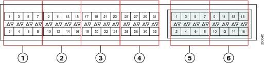
Caution | Adding a second link to a fabric-port-channel port group is disruptive and will automatically increase the available amount of VIF namespace from 63 to 118. Adding further links is not disruptive and the VIF namespace stays at 118. |
Caution | Linking a chassis to two fabric-port-channel port groups does not affect the VIF namespace unless it is manually acknowledged. The VIF namespace is then automatically set to the smaller size fabric port-channel port group usage (either 63 or 118 VIFs) of the two groups. |
For high availability cluster-mode applications, we strongly recommend symmetric cabling configurations. If the cabling is asymmetric, the maximum number of VIFs available is the smaller of the two cabling configurations.
For more information on the maximum number of VIFs for your Cisco UCS environment, see the Configuration Limits document for your hardware and software configuration.
Configuring a Fabric Port Channel
| Step 1 | To include all links from the IOM to the fabric interconnect in a fabric port channel during chassis discovery, set the link grouping preference in the chassis discovery policy to port channel. |
| Step 2 | To include links from individual chassis in a fabric port channel during chassis discovery, set the link grouping preference in the chassis connectivity policy to port channel. |
| Step 3 | After chassis discovery, enable or disable additional fabric port channel member ports. |
What to Do Next
To add or remove chassis links from a fabric port channel after making a change to the chassis discovery policy or the chassis connectivity policy, reacknowledge the chassis. Chassis reacknowledgement is not required to enable or disable chassis member ports from a fabric port channel
Viewing Fabric Port Channels
| Command or Action | Purpose | |
|---|---|---|
| Step 1 | UCS-A# scope eth-server |
Enters Ethernet server mode. |
| Step 2 | UCS-A /eth-server # scope fabric {a | b} |
Enters Ethernet server fabric mode for the specified fabric. |
| Step 3 | UCS-A /eth-server/fabric # show fabric-port-channel [detail | expand] |
Displays fabric port channels on the specified fabric interconnect. |
The following example displays information about configured fabric port channels on fabric interconnect A:
UCS-A# scope eth-server
UCS-A /eth-server # scope fabric a
UCS-A /eth-server/fabric # show fabric-port-channel
Fabric Port Channel:
    Port Channel Id Chassis Id Admin State Oper State       State Reason
    --------------- ---------- ----------- ---------------- ------------
               1025 1          Enabled     Failed           No operational members
               1026 2          Enabled     Up

UCS-A /eth-server/fabric #
Enabling or Disabling a Fabric Port Channel Member Port
| Command or Action | Purpose | |
|---|---|---|
| Step 1 | UCS-A# scope eth-server |
Enters Ethernet server mode. |
| Step 2 | UCS-A /eth-server # scope fabric {a | b} |
Enters Ethernet server fabric mode for the specified fabric. |
| Step 3 | UCS-A /eth-server/fabric # scope fabric-port-channel port-chan-id |
Enters Ethernet server fabric, fabric port channel mode for the specified fabric. |
| Step 4 | UCS-A /eth-server/fabric/fabric-port-channel # scope member-port slot-id port-id |
Enters Ethernet server fabric, fabric port channel mode for the specified member port. |
| Step 5 | UCS-A /eth-server/fabric/fabric-port-channel # {enable | disable} |
Enables or disables the specified member port. |
| Step 6 | UCS-A /eth-server/fabric/fabric-port-channel # commit-buffer |
Commits the transaction to the system configuration. |
The following example disables fabric channel member port 1 31 on fabric port channel 1025 and commits the transaction:
UCS-A# scope eth-server
UCS-A /eth-server # scope fabric a
UCS-A /eth-server/fabric # scope fabric-port-channel 1025
UCS-A /eth-server/fabric/fabric-port-channel # scope member-port 1 31
UCS-A /eth-server/fabric/fabric-port-channel/member-port # disable
UCS-A /eth-server/fabric/fabric-port-channel/member-port* # commit-buffer
UCS-A /eth-server/fabric/fabric-port-channel/member-port #
 Feedback