Cisco UCS C4200 Server Chassis Installation and Service Guide
Bias-Free Language
The documentation set for this product strives to use bias-free language. For the purposes of this documentation set, bias-free is defined as language that does not imply discrimination based on age, disability, gender, racial identity, ethnic identity, sexual orientation, socioeconomic status, and intersectionality. Exceptions may be present in the documentation due to language that is hardcoded in the user interfaces of the product software, language used based on RFP documentation, or language that is used by a referenced third-party product. Learn more about how Cisco is using Inclusive Language.
The Cisco UCS C4200 Server Chassis is a 2RU, rack-mount chassis that provides shared storage, cooling, and power for up to
four removeable compute nodes. Each of the four removable compute nodes can control 6 front-loading drives in the chassis,
for a total of up to 24 small form-factor (SFF), 2.5-inch, SAS/SATA HDDs or SSDs.
With Cisco IMC 4.0(2) and later, each of the four compute nodes can control two front-loading NVMe SSDs, for a total of up
to eight NVME SSDs in the chassis.
For information about compute nodes, see the service note for your compute node:
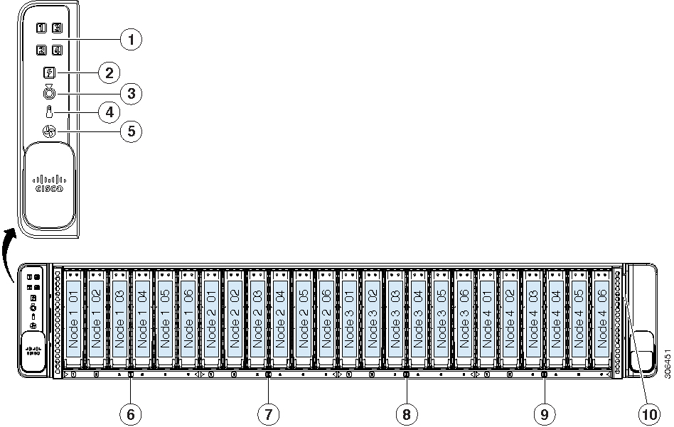
All six bays support SAS/SATA drives; bays 1 and 2 also support NVME drives.
2
Power supply status LED
7
Node 2-controlled drive bays 1—6
All six bays support SAS/SATA drives; bays 1 and 2 also support NVME drives.
3
Locator beacon LED
Activating the locator beacon of any installed compute node activates this chassis locator beacon.
8
Node 3-controlled drive bays 1—6
All six bays support SAS/SATA drives; bays 1 and 2 also support NVME drives.
4
Temperature status LED
9
Node 4-controlled drive bays 1—6
All six bays support SAS/SATA drives; bays 1 and 2 also support NVME drives.
5
Fan status LED
10
Pull-out asset tag
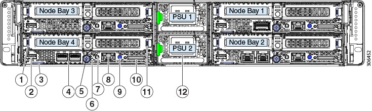
Cisco UCS C4200 Chassis Rear Panel Features
The exact features depend on how many compute nodes are installed in the node bays and which cards are installed in the nodes.
The sample figure below shows a chassis with four Cisco UCS C125 M5 compute nodes installed.
Although the power supplies are the only components native to the chassis in the view below, features of a removeable compute
node are defined to explain network connections for the system. For information about node components, see the Cisco UCS C125 Compute Node Service Note.
Note
All node bays must have either a compute node or a node blank installed to ensure adequate air flow.
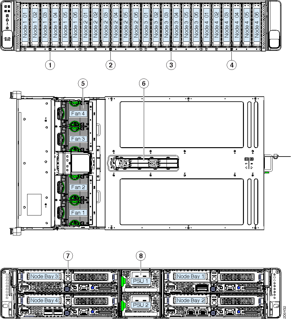
All six bays support SAS/SATA drives; bays 1 and 2 also support NVME drives.
5
Cooling fan modules (four)
Each fan module contains two fans for redundancy.
2
Front-loading drives
Node 2-controlled drive bays 1—6
All six bays support SAS/SATA drives; bays 1 and 2 also support NVME drives.
6
Supercap units (RAID backup)
Each supercap unit backs up one RAID controller in the corresponding node (numbered 1—4).
3
Front-loading drives
Node 3-controlled drive bays 1—6
All six bays support SAS/SATA drives; bays 1 and 2 also support NVME drives.
7
Compute node (up to four)
4
Front-loading drives
Node 4-controlled drive bays 1—6
All six bays support SAS/SATA drives; bays 1 and 2 also support NVME drives.
8
Power supplies (two, redundant 1+1)
Summary of Server Features
The following table lists a summary of server features.
Feature
Description
Chassis
Two rack-unit (2RU) chassis
Central Processor
The chassis supports one to four removable compute nodes, each with two CPUs.
With four nodes, the system can total up to eight CPUs from the AMD EPYC 7000 Series.
Memory
The chassis supports one to four removable compute nodes, each with two CPUs. Each CPU supports up to eight DIMMs.
With four nodes, the system can total up to 64 DIMMs.
Multi-bit error protection
Multi-bit error protection is supported
Baseboard management
Each compute node has a BMC, running Cisco Integrated Management Controller (Cisco IMC) firmware.
Depending on your settings, Cisco IMC can be accessed on each node through its 1-Gb dedicated management port or an adapter
card.
Network and management I/O
The network and management I/O ports for this chassis are on the removeable compute nodes. Each compute node has these connectors
accessible from the rear of the chassis:
One 10/100/1000 Ethernet dedicated management port (RJ-45 connector)
One keyboard/video/mouse (KVM) console connector that is used with a KVM cable, which provides two USB 2.0, one DB-15 VGA,
and one DB-9 serial connector.
One USB 3.0 port
Optional OCP adapter-card Ethernet LAN ports. Depending on which adapter is installed, these ports can be:
Dual 10 Gb BASE-T (RJ-45 connectors)
Dual 10/25 Gb (SFP 28 connectors)
Single 100 Gb (QSFP 28 connector)
Power
Two power supplies, redundant as 1+1:
AC power supplies 2400 W AC each
Do not mix power supply types or wattages in the server.
ACPI
The advanced configuration and power interface (ACPI) 4.0 standard is supported.
Cooling
Four hot-swappable fan modules for front-to-rear cooling.
Each fan module contains two fans for redundancy.
PCIe I/O
Each removeable compute node has two PCIe risers for horizontal installation of PCIe cards such as a RAID controller or Cisco
Virtual Interface Card (VIC).
Storage, front-panel
The chassis can hold up to 24 front-loading, 2.5-inch drives. Each of the four removeable compute nodes can control six of
the front drives.
All six bays controlled by a compute node support SAS/SATA drives. Bays 1 and 2 of the six controlled by a compute node also
support NVMe drives, for a total of up to eight NVMe drives supported in the chassis.
Storage, internal
Each of the four compute nodes have these internal storage options:
Mini-storage module socket, optionally with either:
SD card carrier. Supports up to two SD cards.
M.2 SSD carrier. Supports two SATA M.2 SSDs.
One micro-SD card socket.
Storage management
The system has these options via the installed compute nodes (each node can control six of the front-panel drives):
SAS RAID control via one RAID controller card in each compute node.
SATA pass-through JBOD control via the on-board controller in each compute node.
RAID supercap backup
Up to four supercap units are supported, one for the RAID controller card in each node.
The supercap units have numbered bays and numbered cable connectors in the top of the chassis, corresponding to each numbered
compute node.
Integrated video
Integrated VGA video in each compute node. The DB-15 VGA connector is on the KVM cable that can be used with the KVM connector
on each node.

 Feedback