Status LEDs and Buttons
This section contains information for interpreting LED states.
Front-Panel LEDs

|
LED Name |
States |
|||
|
1 |
Node health The numbers 1 - 4 correspond to the numbered node bays. |
|
||
|
2 |
Power supply status |
|
||
|
3 |
Locator beacon |
Activating the locator beacon on any installed compute node activates this chassis locator beacon.
|
||
|
4 |
Temperature status |
|
||
|
5 |
Fan status |
|
||
|
6 SAS |
SAS/SATA drive fault
|
|
||
|
7 SAS |
SAS/SATA drive activity
|
|
||
|
6 NVMe |
NVMe drive fault |
|
||
|
7 NVMe |
NVMe drive activity LED |
|
Rear-Panel LEDs
The power supply LEDs are the only rear-panel LEDs native to the chassis. Compute node LEDs that repeat on each compute node are also described below. The rear ports and LEDs vary, depending on which adapter card and PCIe cards are installed.

|
LED Name |
States |
|
|
1 |
Node Health Status |
|
|
2 |
Node Power button/Node Power status (One each node) |
|
|
3 |
Node 1-Gb Ethernet dedicated management link speed (One each node) |
|
|
4 |
Node 1-Gb Ethernet dedicated management link status (One each node) |
|
|
5 |
Node locator beacon (One each node) |
|
|
6 |
Power supply status (One bi-color LED each power supply unit) |
AC power supplies:
|
Internal Diagnostic LEDs in the Chassis
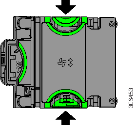
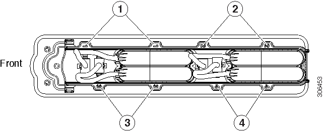
The fan tray in the chassis includes a fault LED for each of the fan modules. The four LEDs are numbered to correspond to the four numbered fan modules.
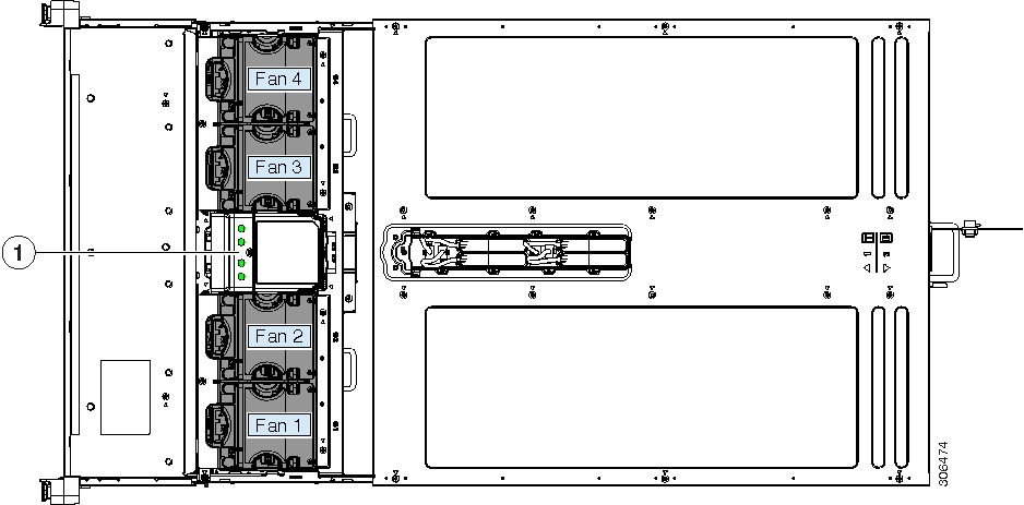
|
1 |
Fan module fault LEDs on fan tray (one LED for each fan module)
|
- |







 Feedback