Overview
The server is orderable in different versions, each with a different front panel/drive-backplane configuration.
-
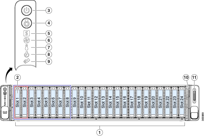
Cisco UCS C240 M5 (UCSC-C240-M5SX)—Small form-factor (SFF) drives, with 24-drive backplane.
-
Front-loading drive bays 1—24 support 2.5-inch SAS/SATA drives.
-
Optionally, front-loading drive bays 1 and 2 support 2.5-inch NVMe SSDs.
-
Optionally, the two rear-loading drive bays support up to two 2.5-inch SAS/SATA drives; or up to two 2.5-inch NVMe SSDs.
-
-
Cisco UCS C240 M5 (UCSC-C240-M5SN)—SFF drives, with 24-drive backplane, NVMe-optimized.
-
Front-loading drive bays 1—8 support 2.5-inch NVMe PCIe SSDs only.
-
Front-loading drive bays 9—24 support 2.5-inch SAS/SATA drives.
-
The two rear-loading drive bays support up to two 2.5-inch NVMe SSDs only.
-
-
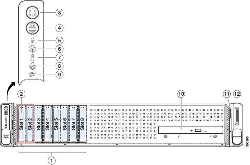
Cisco UCS C240 M5 (UCSC-C240-M5S)—SFF drives, with 8-drive backplane and DVD drive option.
-
Front-loading drive bays 1—8 support 2.5-inch SAS/SATA drives.
-
Optionally, front-loading drive bays 1 and 2 support 2.5-inch NVMe SSDs.
-
Optionally, the two rear-loading drive bays support up to two 2.5-inch SAS/SATA drives; or up to two 2.5-inch NVMe SSDs.
-
-
Cisco UCS C240 M5 (UCSC-C240-M5L)—Large form-factor (LFF) drives, with 12-drive backplane.
-
Front-loading drive bays 1—12 support 3.5-inch SAS/SATA drives.
-
Optionally, front-loading drive bays 1 and 2 support 3.5-inch NVMe SSDs.
-
Optionally, the two rear-loading drive bays support up to two 2.5-inch SAS/SATA drives; or up to two 2.5-inch NVMe SSDs.
-


 Feedback