VersaStack for Hybrid Cloud with Cisco CloudCenter and IBM Spectrum Copy Data Management
Available Languages

VersaStack for Hybrid Cloud with Cisco CloudCenter and IBM Spectrum Copy Data Management
Deployment Guide for VersaStack with Cisco ACI, IBM SVC, Cisco CloudCenter, and IBM Spectrum Copy Data Management Solution
Last Updated: July 26, 2017

About the Cisco Validated Design (CVD) Program
The CVD program consists of systems and solutions designed, tested, and documented to facilitate faster, more reliable, and more predictable customer deployments. For more information visit
http://www.cisco.com/go/designzone.
ALL DESIGNS, SPECIFICATIONS, STATEMENTS, INFORMATION, AND RECOMMENDATIONS (COLLECTIVELY, "DESIGNS") IN THIS MANUAL ARE PRESENTED "AS IS," WITH ALL FAULTS. CISCO AND ITS SUPPLIERS DISCLAIM ALL WARRANTIES, INCLUDING, WITHOUT LIMITATION, THE WARRANTY OF MERCHANTABILITY, FITNESS FOR A PARTICULAR PURPOSE AND NONINFRINGEMENT OR ARISING FROM A COURSE OF DEALING, USAGE, OR TRADE PRACTICE. IN NO EVENT SHALL CISCO OR ITS SUPPLIERS BE LIABLE FOR ANY INDIRECT, SPECIAL, CONSEQUENTIAL, OR INCIDENTAL DAMAGES, INCLUDING, WITHOUT LIMITATION, LOST PROFITS OR LOSS OR DAMAGE TO DATA ARISING OUT OF THE USE OR INABILITY TO USE THE DESIGNS, EVEN IF CISCO OR ITS SUPPLIERS HAVE BEEN ADVISED OF THE POSSIBILITY OF SUCH DAMAGES.
THE DESIGNS ARE SUBJECT TO CHANGE WITHOUT NOTICE. USERS ARE SOLELY RESPONSIBLE FOR THEIR APPLICATION OF THE DESIGNS. THE DESIGNS DO NOT CONSTITUTE THE TECHNICAL OR OTHER PROFESSIONAL ADVICE OF CISCO, ITS SUPPLIERS OR PARTNERS. USERS SHOULD CONSULT THEIR OWN TECHNICAL ADVISORS BEFORE IMPLEMENTING THE DESIGNS. RESULTS MAY VARY DEPENDING ON FACTORS NOT TESTED BY CISCO.
CCDE, CCENT, Cisco Eos, Cisco Lumin, Cisco Nexus, Cisco StadiumVision, Cisco TelePresence, Cisco WebEx, the Cisco logo, DCE, and Welcome to the Human Network are trademarks; Changing the Way We Work, Live, Play, and Learn and Cisco Store are service marks; and Access Registrar, Aironet, AsyncOS, Bringing the Meeting To You, Catalyst, CCDA, CCDP, CCIE, CCIP, CCNA, CCNP, CCSP, CCVP, Cisco, the Cisco Certified Internetwork Expert logo, Cisco IOS, Cisco Press, Cisco Systems, Cisco Systems Capital, the Cisco Systems logo, Cisco Unified Computing System (Cisco UCS), Cisco UCS B-Series Blade Servers, Cisco UCS C-Series Rack Servers, Cisco UCS S-Series Storage Servers, Cisco UCS Manager, Cisco UCS Management Software, Cisco Unified Fabric, Cisco Application Centric Infrastructure, Cisco Nexus 9000 Series, Cisco Nexus 7000 Series. Cisco Prime Data Center Network Manager, Cisco NX-OS Software, Cisco MDS Series, Cisco Unity, Collaboration Without Limitation, EtherFast, EtherSwitch, Event Center, Fast Step, Follow Me Browsing, FormShare, GigaDrive, HomeLink, Internet Quotient, IOS, iPhone, iQuick Study, LightStream, Linksys, MediaTone, MeetingPlace, MeetingPlace Chime Sound, MGX, Networkers, Networking Academy, Network Registrar, PCNow, PIX, PowerPanels, ProConnect, ScriptShare, SenderBase, SMARTnet, Spectrum Expert, StackWise, The Fastest Way to Increase Your Internet Quotient, TransPath, WebEx, and the WebEx logo are registered trademarks of Cisco Systems, Inc. and/or its affiliates in the United States and certain other countries.
All other trademarks mentioned in this document or website are the property of their respective owners. The use of the word partner does not imply a partnership relationship between Cisco and any other company. (0809R)
© 2017 Cisco Systems, Inc. All rights reserved.
Table of Contents
VersaStack data protection and DevOps with data availability
VersaStack Primary data center
VersaStack Secondary Data Center
VersaStack Hybrid Cloud Network Configuration
Cisco CloudCenter Configuration
VersaStack VMware CloudCenter Appliance Installation
IBM Bluemix CloudCenter Installation
RabbitMQ (AMQP) and CCO Configuration at IBM Bluemix
Configure and Setup CloudCenter Manager
VersaStack Private Cloud Configuration
VersaStack DR Cloud Configuration
IBM Bluemix Public Cloud Configuration
OpenCart Application Deployment using CloudCenter
Deploying Production Instance of OpenCart Application on VersaStack On-premises
Deploying Dev-Test Instance of OpenCart Application at IBM Bluemix Cloud
VersaStack Data Replication Configuration
Configure the Ethernet Ports on the Partner Systems
Configuring the Ethernet ports on SVC Cluster
Configuring the Ethernet Ports on IBM Storwize V7000
Create and Configure the IP Partnership on Each Partner System
Configuring the IP partnership on IBM SVC Cluster
Configure the IP Partnership on IBM V7000 Remote System
IBM Spectrum Copy Data Management Configuration
IBM Spectrum CDM Virtual Machine Installation
IBM Spectrum CDM Configuration
VersaStack Application Protection using IBM Copy Data Management
Create a Backup Job Definition - Oracle
Create a Backup Job Definition - SQL
Create a Restore Job Definition - Oracle
Create a Restore Job Definition - SQL
DevOps with Data Availability for VersaStack
Model MSSQL Application using CloudCenter
Deploy the MSSQL Application on VersaStack Primary Data Center
Deploy the MSSQL Application on VersaStack Secondary Data Center
Automated Database Restore to the Dev-Test Instance using CDM
Registering the Application Server through REST
Running MSSQL Restore Job through REST
Cisco CloudCenter integration with Cisco ACI
Integrating Cisco CloudCenter with Cisco Prime Service Catalog
Installation of Cisco Prime Services catalog
Configuring Permissions and Presentation for CloudCenter Services.
Cisco Validated Designs (CVDs) deliver systems and solutions that are designed, tested, and documented to facilitate and improve customer deployments. These designs incorporate a wide range of technologies and products into a portfolio of solutions that have been developed to address the business needs of the customers and to guide them from design to deployment.
Customers looking to deploy applications using shared data center infrastructure face a number of challenges. A recurrent infrastructure challenge is to achieve the levels of IT agility and efficiency that can effectively meet the business objectives. Addressing these challenges requires having an optimal solution with the following key characteristics:
· Availability: Helps ensure applications and services availability at all times with no single point of failure
· Flexibility: Ability to support new services without requiring underlying infrastructure modifications
· Efficiency: Facilitate efficient operation of the infrastructure through re-usable policies
· Manageability: Ease of deployment and ongoing management to minimize operating costs
· Scalability: Ability to expand and grow with significant investment protection
· Compatibility: Minimize risk by ensuring compatibility of integrated components
Cisco and IBM have partnered to deliver a series of VersaStack solutions that enable strategic data center platforms with the above characteristics. VersaStack solution delivers an integrated architecture that incorporates compute, storage and network design best practices thereby minimizing IT risks by validating the integrated architecture to ensure compatibility between various components. The solution also addresses IT pain points by providing documented design guidance, deployment guidance and support that can be used in various stages (planning, designing and implementation) of a deployment.
Combining Cisco CloudCenter and IBM Spectrum Copy Data Management technologies in VersaStack implementations creates VersaStack for Hybrid Cloud with a hybrid cloud management layer enabling orchestration, deployment, management and migration of applications across data center, Public Cloud and Private Cloud environments. The solution allows enterprises to:
· Improve business agility by deploying applications now and moving to an optimal environment later
· Migrate applications and data to the cloud
· Enable end-to-end data management through tracking and management of copies
VersaStack for Hybrid Cloud provides the flexibility to choose the best deployment option for a wide variety of enterprise IT workloads, while freeing up resources in the data center for new-generation applications and cognitive workloads.
Introduction
VersaStack solution is a pre-designed, integrated and validated architecture for data center that combines Cisco UCS servers, Cisco Nexus family of switches, Cisco MDS fabric switches and IBM Storwize and FlashSystem Storage Arrays into a single, flexible architecture. VersaStack is designed for high availability, with no single points of failure, while maintaining cost-effectiveness and flexibility in the design to support a wide variety of workloads.
VersaStack design can support different hypervisor options, bare metal servers and can also be sized and optimized based on customer workload requirements. VersaStack design discussed in this document has been validated for resiliency (under fair load) and fault tolerance during system upgrades, component failures, and partial as well as total power loss scenarios.
VersaStack for Hybrid Cloud provides a powerful Hybrid Cloud solution using VersaStack converged infrastructure extended to IBM Bluemix Public Cloud and inclusion of Cisco CloudCenter and IBM Spectrum Copy Data Management software components to deploy, provision, and manage applications and data in hybrid cloud environments
This solution supports both traditional and emerging cloud native applications; it delivers extensive IT automation and hybrid cloud versatility for applications and data.
In addition to providing a simplified, comprehensive, on-premises IT infrastructure with agile cloud connectivity and data management, VersaStack for Hybrid Cloud can be used by enterprises to gain a variety of benefits, such as:
· “Converged cloud” IT infrastructure that allows easy movement of applications and data across on-premises and cloud environments such as IBM Bluemix Infrastructure to optimize cost and performance
· End-to-end copy data management to lower storage capacity requirements and accelerate application development and testing
· IT as a service to balance user self-service on-demand deployment and management in environments with central governance and control
· Capacity utilization optimization with automated standup and teardown of applications and the ability to supplement data center storage with cloud capacity on demand
· Hybrid cloud application migration to enable migration of existing applications from one environment to another
· DevOps and CI/CD automation to facilitate automated continuous application deployment to existing continuous delivery, with acceleration of the software development lifecycle using an integrated tool chain
Figure 1 VersaStack for Hybrid Cloud Solution Overview
Audience
The intended audience of this document includes, but is not limited to, sales engineers, field consultants, professional services, IT managers, partner engineering, and customers who want to take advantage of an infrastructure built to deliver IT efficiency and enable IT innovation.
Purpose of this Document
This document provides step by step configuration and implementation guidelines for setting up VersaStack for Hybrid Cloud. The following design elements distinguish this version of VersaStack from previous models:
· Integration of Cisco CloudCenter with VersaStack with Cisco ACI and IBM SVC as Private Cloud
· Integration of Cisco CloudCenter with IBM Bluemix as Public Cloud
· Secure Connectivity between the VersaStack Private Cloud and the IBM Bluemix Public Cloud
· Cisco ONE Enterprise Cloud Suite, Cisco CloudCenter
· Cisco CloudCenter integration with Cisco ACI
· IBM Spectrum Copy Data Management
· IBM Storwize V7000 as secondary storage for data protection
· Optional: Support for Cisco Prime Services Catalog
For more information on previous VersaStack models, please refer the VersaStack guides at:
![]() The terms VersaStack Data Center and VersaStack Private Cloud have been used interchangeably within this document; both of these represent the VersaStack converged infrastructure on-premises within the solution.
The terms VersaStack Data Center and VersaStack Private Cloud have been used interchangeably within this document; both of these represent the VersaStack converged infrastructure on-premises within the solution.
![]() IBM Bluemix and IBM Softlayer Public Cloud have been used interchangeably throughout this document. IBM Softlayer Cloud has been leveraged as the Public Cloud option for this solution and is currently under the IBM Bluemix brand name.
IBM Bluemix and IBM Softlayer Public Cloud have been used interchangeably throughout this document. IBM Softlayer Cloud has been leveraged as the Public Cloud option for this solution and is currently under the IBM Bluemix brand name.
Architecture
VersaStack for Hybrid Cloud architecture aligns with the converged infrastructure configurations and best practices as identified in the previous VersaStack releases. The system includes hardware and software compatibility support between all components and aligns to the configuration best practices for each of these components. All the core hardware components and software releases are listed and supported on both:
Cisco compatibility list:
http://www.cisco.com/en/US/products/ps10477/prod_technical_reference_list.html
IBM Interoperability Matrix:
http://www-03.ibm.com/systems/support/storage/ssic/interoperability.wss
Physical Topology
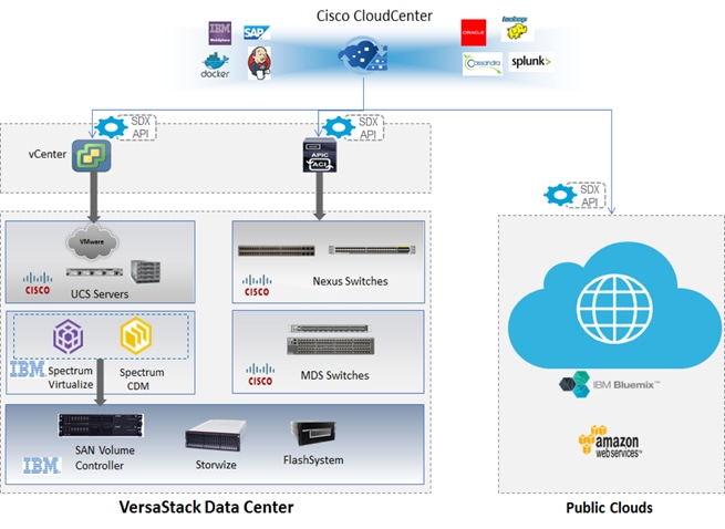
The VersaStack for Hybrid Cloud architecture is built as an extension of the VersaStack Private Data Center or VersaStack cloud to the IBM Bluemix Public Cloud. The VersaStack Private Cloud architecture is the main building block with in this solution and is based on the “VersaStack for Data Center with Cisco Application Centric Infrastructure and IBM SAN Volume Controller” Design Guides.
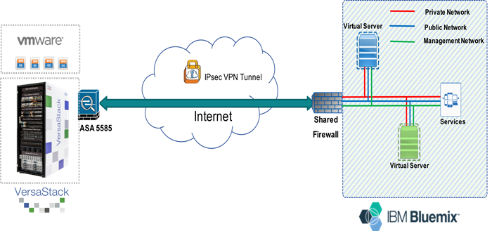
Figure 2 shows the physical topology of the VersaStack for Hybrid Cloud Solution, it consists of two environments: an on-premise VersaStack Data Center and off-premises Bluemix Public Cloud. Both environments are connected via IPSec VPN link across the Internet.
Figure 2 VersaStack for Hybrid Cloud Physical Topology
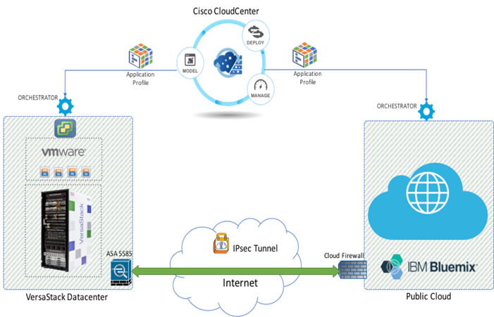
The VersaStack Data Center includes an ASA5585 firewall running site-to-site VPN tunnel to an edge gateway at the IBM Bluemix Cloud. This network layer is used to support communication between on-prem and off-prem environments. The Cisco CloudCenter shown at the top of the architecture in Figure 2 provides single pane of glass for the Multi-Cloud management. CloudCenter users can create and deploy an application profile to any target data center or cloud environments. The cloud-specific, multitenant orchestrator shown above runs at the target environment and natively deploys the application profile in a way that optimizes security, increases application performance, and maintains application portability. By using cloud-specific orchestrators, Cisco CloudCenter can abstract away the specifics of the configuration and as a result users get the ability to provide their requirements and select the application profiles and get fully configured and deployed applications within minutes in any environment on-prem or off-prem.
VersaStack data protection and DevOps with data availability
The solution consists of two VersaStack private data centers, primary data center used for production applications and the secondary data center used for disaster recovery as well as for deploying Dev-Test workloads.
Both these environments can be connected over the WAN via any connectivity the enterprises have, the example shown below is via VPN link across the Internet. IBM Spectrum CDM provides the capability of protecting applications locally on the production VersaStack environment and also providing site level protection by replicating and orchestrating application data across the VersaStack primary and secondary data centers.
IBM Spectrum Copy Data Management delivers the first “In Place” Copy Data Management platform, which works with IBM Spectrum Virtualize in VersaStack and drive operational efficiencies, cost savings and provides better leverage of your storage assets.
IBM Spectrum Copy Data Management delivers a robust in-place copy data management platform, giving IT a single enterprise-wide system that replaces the complicated set of products, tools and scripts that are collectively used today. IBM Spectrum Copy Data Management is a software-only solution that installs as a virtual machine on VersaStack infrastructure, requires no agents and deploys within 15 minutes. IBM Spectrum Copy Data Management automated workflows allow clients to streamline Copy Data management operations for VersaStack environments.
Figure 3 VersaStack Data Protection Architecture
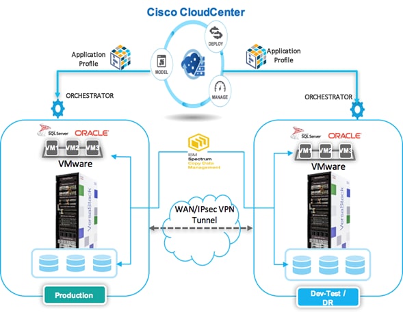
Cisco CloudCenter and IBM Spectrum Copy data management work closely to automate the deployment of test or development environments instantly on VersaStack. Cisco CloudCenter can provision application profiles and deploy virtual machines templates that include the applications instances at either of the VersaStack Data Centers. Through a simple script driven policy Cisco CloudCenter can leverage the near-production copies of the data cataloged in IBM Spectrum Copy Data Management to orchestrate the provisioning of data volumes to these virtual machines. The combination of Cisco CloudCenter and IBM Spectrum Copy Data Management provides a powerful Dev-Test automation that not only creates the appropriate application profiles instantly but also enables developers and QA engineers to perform their jobs more efficiently.
VersaStack Primary data center
The VersaStack Primary data center hosts production applications within the solution and is connected to the IBM Bluemix Public Cloud with in the Hybrid cloud deployment architecture. The existing deployment of the VersaStack Data Center architecture is assumed, and the setup of these resources will have dependencies covered in the VersaStack with Cisco ACI and IBM SVC Deployment Guide.
Figure 4 VersaStack Private Cloud Architecture
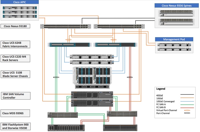
This VersaStack datacenter with Cisco ACI and IBM SVC solution utilizes Cisco UCS platform with Cisco UCS B200 M4 half-width blades and Cisco UCS C220 M4 rack mount servers connected and managed through Cisco UCS 6248 Fabric Interconnects and the integrated Cisco UCS manager. These high-performance servers are configured as stateless compute nodes where ESXi hypervisor is loaded using SAN (iSCSI and FC) boot. The boot disks to store ESXi hypervisor image and configuration along with the block and file based datastores to host application Virtual Machines (VMs) are provisioned on the IBM storage devices.
IBM SVC nodes, IBM FlashSystem 900 and IBM Storwize V5030 are all connected using a Cisco MDS 9396S based redundant FC fabric. To provide FC based storage access to the compute nodes, Cisco UCS Fabric Interconnects are connected to the same pair of Cisco MDS 9396S switches and zoned appropriately. To provide iSCSI based storage access, IBM SVC is connected directly to the Cisco Nexus 93180 leaf switches. A10GbE port from each IBM SVC node is connected to each of the two Cisco Nexus 93180 leaf switches providing an aggregate bandwidth of 40Gbps.
VersaStack Secondary Data Center
The VersaStack Secondary data center is a secondary site within the solution connected to VersaStack primary data center over the WAN, it hosts the dev-test application instances with in the solution and is also leveraged as a disaster recovery site for the primary data center. The data replication is setup between the primary and secondary storage arrays across the data centers and the data orchestration is handled by IBM Spectrum Copy Data Management. The production data copies of applications will be leveraged by application instances deployed for Dest-Test purposes.
The VersaStack secondary data center architecture is based on the VersaStack data center with IBM Storwize V7000 design with in this solution.
![]() The Secondary site can be based on any storage array part of IBM Storwize family which can be part of the replication relationship. The base infrastructure configuration of the secondary VersaStack Data Center is not discussed in this document and is assumed that there is already a VersaStack based secondary site deployed.
The Secondary site can be based on any storage array part of IBM Storwize family which can be part of the replication relationship. The base infrastructure configuration of the secondary VersaStack Data Center is not discussed in this document and is assumed that there is already a VersaStack based secondary site deployed.
For design information on VersaStack models that can be leveraged as secondary VersaStack data centers, please refer the VersaStack guides at:
Software Revisions
Table 1 below outlines the hardware and software versions used for the solution validation. It is important to note that Cisco, IBM, and VMware have interoperability matrices that should be referenced to determine support for any specific implementation of VersaStack. See the following links for more information:
· IBM System Storage Interoperation Center
· Cisco UCS Hardware and Software Interoperability Tool
Table 1 Hardware and Software Revisions
| Layer |
Device |
Image |
Comments |
| Compute |
Cisco UCS Fabric Interconnects 6200 Series, Cisco UCS B200 M4, Cisco UCS C220 M4 |
3.1(2b) |
Includes the Cisco UCS-IOM 2208XP, Cisco UCS Manager, and Cisco UCS VIC 1340 |
| Cisco ESXi eNIC Driver |
2.3.0.10 |
Ethernet driver for Cisco VIC |
|
| Cisco ESXi fnic Driver |
1.6.0.28 |
FCoE driver for Cisco VIC |
|
| Network |
Cisco Nexus Switches |
12.0(2h) |
iNXOS |
| Cisco APIC |
2.0(2h) |
ACI release |
|
| Cisco MDS 9396S |
7.3(0)D1(1) |
FC switch firmware version |
|
| Storage |
IBM SVC |
7.7.1.3 |
Software version |
| IBM Storwize V5030 |
7.7.1.3 |
Software version |
|
| IBM FlashSystem 900 |
1.4.5.0 |
Software version |
|
| Software |
VMware vSphere ESXi |
6.0 update 2 |
Software version |
| VMware vCenter |
6.0 update 2 |
Software version |
|
| Cisco Virtual Switch Update Manager |
2.1 |
Software version |
|
| Cisco AVS |
5.2(1)SV3(2.2) |
Software version |
|
|
|
CloudCenter |
4.7.3 |
Software version |
|
|
IBM Spectrum Copy Data Management |
2.2.6 |
Software version |
|
|
Cisco Prime Services Catalog |
12.0 |
Software version |
Considerations
Customer environments and the number of VersaStack Data Center components will vary from site to site; deployment of the VersaStack private datacenters is not covered in this document and is assumed that the customers already have VersaStack infrastructure implemented. The solution includes Cisco CloudCenter and IBM Spectrum Copy Data Management used for various use cases. Customers can leverage these components individually or combined together depending on their needs.
Softlayer offers multiple network connectivity options that can be leveraged to connected the On-premises VersaStack to the Softlayer Public Cloud, internet based IPSec VPN connectivity has been leveraged for this solution.
This document is intended to enable customers and partners to fully configure the customer environment and during this process, various steps may require the use of customer-specific naming conventions, IP addresses, and VLAN schemes, as well as application dependencies and details.
Finally, to indicate that you should include information pertinent to your environment in a given step, <text> appears in the configuration procedures in the document.
This section provides a detailed procedure of Network Configuration for connectivity between the VersaStack Primary Data Center and the IBM Bluemix Public Cloud.
Network connectivity between VersaStack Primary Data Center and IBM Bluemix Cloud is typically achieved in one of two ways: a direct link connection to the IBM Bluemix Cloud, or an Internet-based routing to an IBM Bluemix hosted environment.
The Network connectivity tested for this solution is Internet based and has a site-to-site IPSec VPN Tunnel established for communication across the locations. The main purpose of this site-to-site VPN Tunnel is to enable communication between the management components deployed across the locations.
For customers who need data transfer between the locations need to have an IBM Bluemix account with Custom Private Addressing (CPA) enabled. For the validation of this solution we have used the default IBM Bluemix account and we are limited to management communication traffic only across the Private and Public Clouds.
For details about the CPA account, see: http://www.softlayer.com/custom-private-addressing
To establish a VPN tunnel, complete the following steps:
1. Login to Softlayer portal using your account credentials.
2. Click Network and Select IPSec VPN.
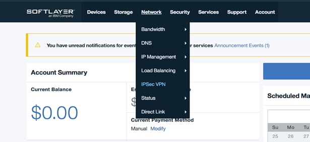
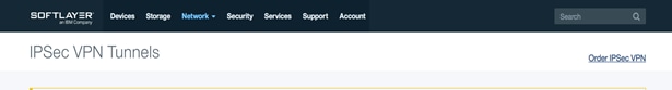
3. Click Order IPSec VPN.
4. Select DAL09 – Dallas as the location and click Continue.
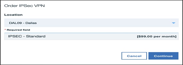
5. Click Place Order to order the IPSec VPN service.
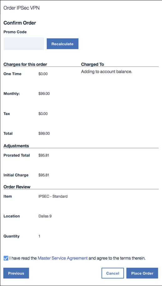
6. When the order is processed, you will have the VPN created that will be listed under IPSec VPN Tunnels.
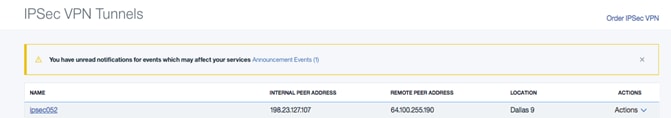
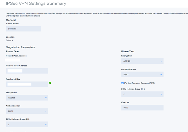
7. Click the VPN Tunnel Name and provide the following information:
![]() You will need to know the following information for the remote side of the IPSEC VPN. When you have this information available, you will be able to configure the basic negotiation parameters of the VPN connection.
You will need to know the following information for the remote side of the IPSEC VPN. When you have this information available, you will be able to configure the basic negotiation parameters of the VPN connection.
· Static IP Address for VPN Endpoint
· Preshared Key (Password)
· Encryption Algorithm (DES, 3DES, AES128, AES192, AES256)
· Authentication (MD5, SHA1, SHA256, for phases 1 and 2)
· Diffie-Hellman Group (for phases 1 and 2)
· Is perfect Forward Secrecy (PFS) used?
· Keylife Time (for phases 1 and 2)
![]() The system measures the Keylife Time value in seconds.
The system measures the Keylife Time value in seconds.
8. In the VPN connection properties, you will need to define the networks on the remote end of the tunnel as well as the local networks for the tunnel. In the “Protected Customer (Remote) Subnet”, enter the private IP address space in CIDR notation for the remote, non-Softlayer end of the IPSEC tunnel.
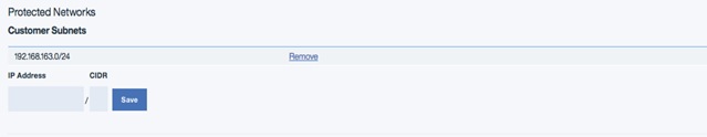
![]() For example, if your network on the remote end of the tunnel uses a single subnet 192.168.163.0 with a netmask of 255.255.255.0, you would enter IP Address 192.168.163.0 / CIDR 24 for the “Protected Customer (Remote) Subnet” section.
For example, if your network on the remote end of the tunnel uses a single subnet 192.168.163.0 with a netmask of 255.255.255.0, you would enter IP Address 192.168.163.0 / CIDR 24 for the “Protected Customer (Remote) Subnet” section.
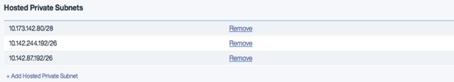
9. Click Add Hosted Private Subnet to add the private networks that will be used at softlayer for Virtual Server deployments.
ASA Configuration
As mentioned earlier, Cisco ASA has been used on the VersaStack Private Cloud to create the IPSec VPN Tunnel, any supported customer device capable of supporting site-to-site IPSec VPN can be used to create the VPN Tunnel.
To configure Cisco ASA to support the VPN Tunnel, complete the following steps:
1. If the ASA interfaces are not configured, ensure that you configure at least the IP addresses, interface names, and security-levels for Inside and Outside Interfaces:
interface GigabitEthernet0/0
nameif outside
security-level 0
ip address x.x.x.x x.x.x.x!
interface GigabitEthernet0/1.11
vlan 11
nameif versastack
security-level 90
ip address 192.168.163.1 255.255.252.0
!
![]() Make sure that there is connectivity to both the internal and external networks, and especially to the remote peer that will be used in order to establish a site-to-site VPN tunnel. You can use a ping in order to verify basic connectivity.
Make sure that there is connectivity to both the internal and external networks, and especially to the remote peer that will be used in order to establish a site-to-site VPN tunnel. You can use a ping in order to verify basic connectivity.
2. Create ISAKMP policy, ISAKMP is used to establish the initial asymmetrically encrypted channels between the two endpoints so that they can securely negotiate a pair of one-way IPsec security associations (SAs).
3. On the ASA, enter the configuration mode:
Config terminal
4. Use the following commands to create the policy:
isakmp policy 10
authentication pre-share
encryption aes
hash sha
group 2
lifetime 28800
exit
isakmp enable outside
5. Create an IPsec transform set that establishes the encryption and authentication (HMAC) methods to be employed by the IPsec Security Associations (SAs).
6. In the configuration mode, enter the following commands:
crypto ipsec transform-set ESP-AES-128-SHA esp-aes esp-sha-hmac
7. Create an access list to match plain (unencrypted) traffic which should be encrypted and routed through the IPsec tunnel between the two LANs. You need to match traffic going between the networks, sample networks are shown in the following commands:
access-list softlayer-acl extended permit ip 192.168.163.0 255.255.255.0 10.142.87.192 255.255.255.192
access-list softlayer-acl extended permit ip 192.168.163.0 255.255.255.0 10.142.244.192 255.255.255.192
access-list softlayer-acl extended permit ip 192.168.163.0 255.255.255.0 10.173.142.80 255.255.255.240
access-list softlayer-acl extended permit ip 192.168.163.0 255.255.255.0 10.48.122.64 255.255.255.192
8. Create a Tunnel group which holds tunnel configuration parameters, namely the connection type and authentication method. Since you are using pre-shred key authentication, you need to name our tunnel group as the IP address of the remote peer.
tunnel-group 198.23.127.107 type ipsec-l2l
tunnel-group 198.23.127.107 ipsec-attributes
pre-shared-key <MyKey>
9. Create and Apply a Crypto Map:
crypto map outside_map 3 match address softlayer-acl
crypto map outside_map 3 set pfs
crypto map outside_map 3 set peer <Peer IP Address>
crypto map outside_map 3 set transform-set ESP-AES-128-SHA
10. Apply the crypto map to the outside interface on firewall to complete the configuration:
crypto map outside_map interface outside
exit
Network Address Translation/Assigned Static NAT Subnets
With the IPSEC VPN, you are allowed to define Private IP addresses on SoftLayer’s network which will route traffic to remote subnets on the other end of the VPN connection. This allows you to have Private Internet traffic be forwarded to one of your internal IP addresses of a machine behind your VPN, without exposing the remote location to full Internet access.
To configure a remote VPN IP with a static NAT entry, complete the following steps:
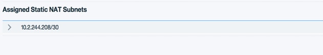
1. Select the arrow for the drop-down of the subnet list in the “Assigned Static NAT subnets” section. Each IP in the subnet will be displayed.
2. Enter the IP on the remote end of the VPN connection under the “Customer IP” column and enter a name for the mapping under the “Name” column.
3. Click Update Device to apply the configuration.
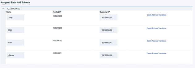
4. This will setup a static one to one network translation for the return traffic which would be used by your hosts behind the Softlayer VPN concentrator to communicate with the hosts behind the remote VPN peer. For example, all traffic for Softlayer IP 10.2.244.211 will get translated/ forwarded to the Customer vCenter IP 192.168.163.100. This will eliminate the need for additional route entries on the Softlayer server.
VLAN Spanning
All servers automatically have access to the rich feature set available on the Softlayer private network, regardless of their location. However, servers on separate VLANs will not be able to communicate with each other over the private network. When enabled, the private network VLAN spanning service allows all private network VLANs to communicate with one another. Future servers will be added as they are provisioned.
1. While logged in to Softlayer Control panel, click Network.

2. Click IP Management and select VLANs.

3. Expand Span and check the VLAN Spanning radio button to enable communication across private networks.

This section provides detailed instructions for installing Cisco CloudCenter components across VersaStack Private Clouds and the IBM Bluemix Public Cloud environments. After the procedures are completed, CloudCenter environment will be installed and configured.
Figure 5 shows the various CloudCenter Components deployed across the two Cloud regions: VersaStack Private Cloud environments and the IBM Bluemix Cloud. Some of the components shown are optional and can be deployed based on the customer's requirements.
Figure 5 also shows the minimal port requirements for inter-component communication. Production environments typically are secured by only allowing communication through the specified ports for security reasons.
For detailed information about the CloudCenter components and deployment requirements along with installation procedures, please refer to the CloudCenter documentation: http://docs.cloudcenter.cisco.com/display/CCD46/d.+Version+4.6+and+4.7+Home
Figure 5 Cisco CloudCenter Components and Network Requirements

CloudCenter components are installed in the following two ways:
Appliances – Installation method for VersaStack Private Clouds. The Appliance Installation components are provided by Cisco and contains specific images that are tailored for some cloud providers.
Installers – Installation method for the IBM Bluemix Public Cloud. Cisco does not provide CloudCenter appliances for IBM Bluemix deployments. The Manual Installation option allows you to install the necessary CloudCenter components. All installer files are available in the ...-installer-artifacts.tar file (available from software.cisco.com to a folder of your choice).
VersaStack VMware CloudCenter Appliance Installation
To Setup CloudCenter using appliances for VersaStack VMware Private Cloud, complete the following:
VersaStack Private Cloud requires the installation of 3 VMs via OVA files:
· CloudCenter Manager (CCM)
· CloudCenter Orchestrator (CCO)
· RabbitMQ (AMQP)
VersaStack DR/Dev-Test Secondary cloud requires the installation of 2 VMs via OVA files:
· CloudCenter Orchestrator (CCO)
· RabbitMQ (AMQP)
To prepare infrastructure for the appliance approach, complete the following steps:
1. Download OVA files from software.cisco.com and store them locally, they can be deployed in vCenter using web client or thick client.
2. Open a web browser and navigate to your vCenter web client < https://<IP address or FQDN of vCenter> at VersaStack Primary Data Center.
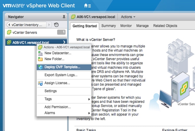
3. When logged in, click vCenter Inventory Lists > vCenter Servers.
4. Right-click the vCenter server and click Deploy OVF Template.
5. From the vSphere Web Client, Select Hosts and Clusters > Actions > Deploy OVF Template.
6. Specify the source location as Local File and browse to the OVA file location and select the CCO OVA file.
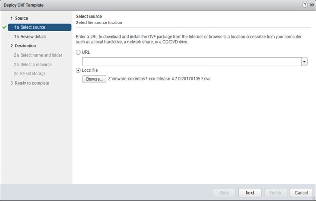
7. Click Next, then click Next again.
8. Review the license agreement. Accept and Click Next.
9. Click Next on the Select name and folder screen.
![]() The datastore, management cluster and the network can be different based on customer specific VersaStack environment.
The datastore, management cluster and the network can be different based on customer specific VersaStack environment.
10. Select <MGMT-Hosts cluster> on the Select a resource screen.
11. Select <infra_datastore_1> as the Datastore and click Next, leave the other options as default.
12. Make sure you have Management Mapped to <IB-Mgmt> in the Setup networks screen and click Next.
13. Review the summary screen, Select Power on after deployment and click Finish.

14. Repeat the above steps and deploy the CCM and RabbitMQ (AMQP) appliances using the OVA files downloaded earlier.
15. When the installation of the OVAs is complete, power on the CCO and RabbitMQ VMs (NOT the CCM).
CCO Configuration
To configure the CCO server at the VersaStack primary data center, complete the following steps:
1. When the CCO is powered on, access the VM using vSphere console. Login with the default credentials (root / welcome2cliqr).
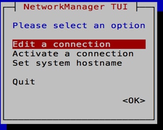
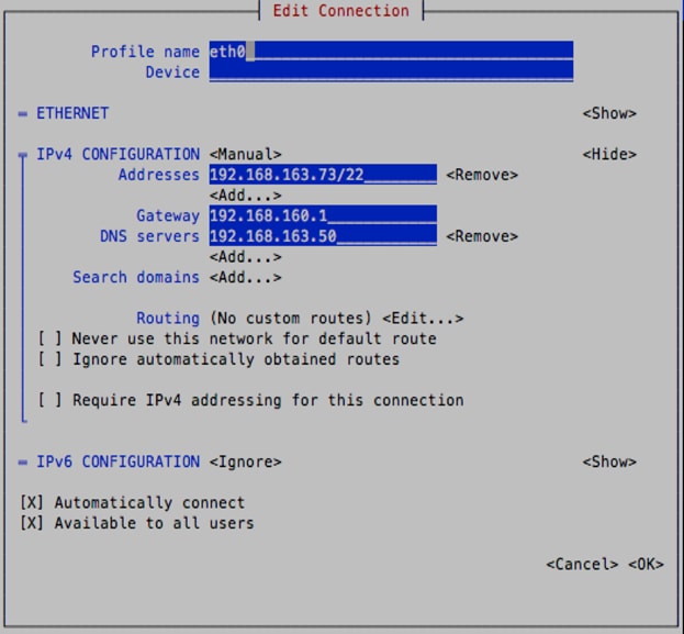
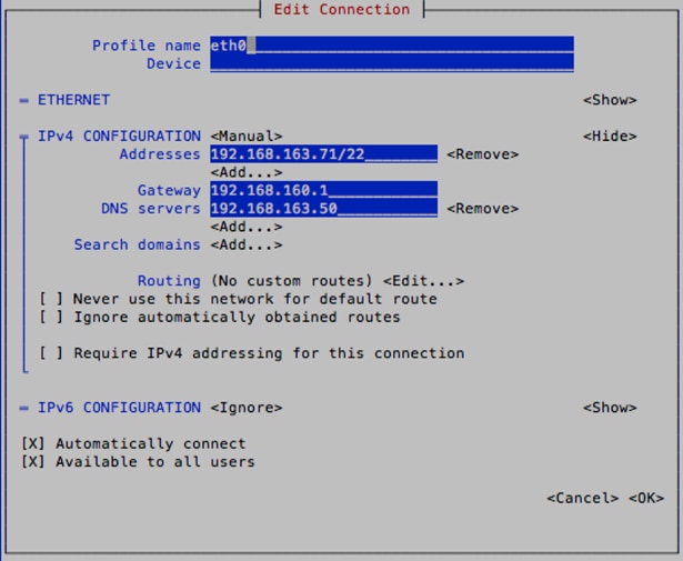
2. Type nmtui to bring up the Network Manager. Press Enter once to select Edit a connection and then press Enter again to select eth0.

3. Use the arrow keys and select IPv4 CONFIGURATION. Change the value to <Manual> and then select <Show>.
4. Select <Add> and input the management address for the CCO. Indicate the subnet using CIDR notation. Follow the same steps above to configure the Gateway and the DNS servers.
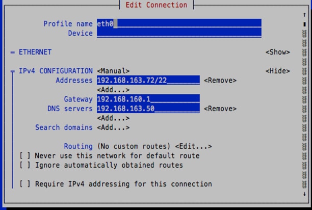
5. When complete, select OK and then Quit to close the wizard. Verify the changes with ifconfig.

6. Type vi /etc/hostname and change the hostname. Typically, this should match the VM name, but that is not required. Save the file and exit.
![]()
![]()
7. Type vi /etc/hosts and append the above hostname to the hosts file. Save the file and exit.
![]()
![]()
8. Type cd /usr/local/osmosix/bin at the shell prompt.
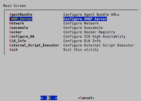
9. Type ./cco_config_wizard.sh to start the Server Config Utility. Select <OK>.

10. Use the arrow keys to select AMQP_Server. Enter the IP address of the RabbitMQ VM, which will be configured in the next section. Keep the default port of 5671.
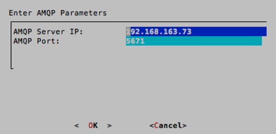
11. Press Enter and when prompted to make the changes, select <Yes> and then <OK>.
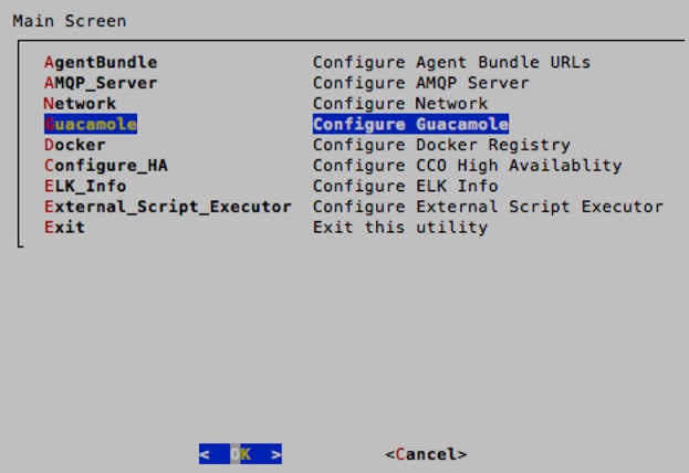
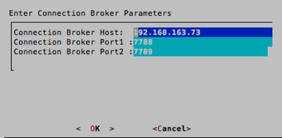
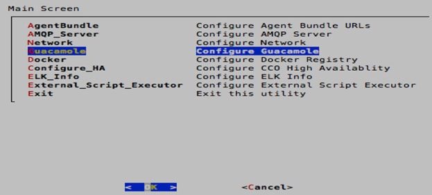
12. When back on the main selection screen of the wizard, select Guacamole. Enter the IP address of the RabbitMQ (AMQP) VM. Keep the default ports of 7788 and 7789. Press Enter and when prompted to make the changes, select <Yes> and then <OK>.
13. Use the arrow keys to select Exit. When prompted to restart the server, select <Yes>.
14. This will only restart the tomcat service, however, a full reboot of the VM is recommended. Type reboot into the Linux command prompt.
RabbitMQ (AMQP) Configuration
To configure the RabbitMQ (AMQP) server at VersaStack primary data center, complete the following steps:
1. The configuration for RabbitMQ is mostly similar to the CCO configuration done above. Type nmtui to open the NetworkManager. Configure the IPv4 CONFIGURATION.
2. When the IP address, gateway and DNS have been set, exit the utility and modify the hostname and hosts files with the new hostname.
3. Type rm -f /usr/local/osmosix/etc/.RABBITINSTALLED. This file needs to be deleted.
4. Type reboot in the Linux prompt to reload the VM.
![]() The RabbitMQ service is tied to the hostname. When /usr/local/osmosix/etc/.RABBITINSTALLED is removed and the server is rebooted, the file will be regenerated automatically and will be associated to the new hostname. Should you ever rename the host you will have to repeat this workflow.
The RabbitMQ service is tied to the hostname. When /usr/local/osmosix/etc/.RABBITINSTALLED is removed and the server is rebooted, the file will be regenerated automatically and will be associated to the new hostname. Should you ever rename the host you will have to repeat this workflow.
5. When the VM is rebooted, login to the VM and type cd /usr/local/osmosix/bin and then ./gua_config_wizard.sh
6. Press <OK> to enter the Server Config Utility.

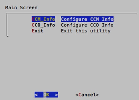
7. On the main selection screen of the wizard, select CCM_Info to configure the CCM IP address. Type in the IP address of the CCM and then press Enter when prompted to make the changes, select <Yes>.


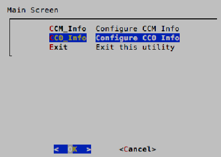
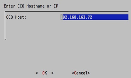
8. When back on the main selection screen of the wizard, select CCO_Info to configure the CCO IP address. Type in the IP address of the CCO and then press Enter when prompted to make the changes, select <Yes>.
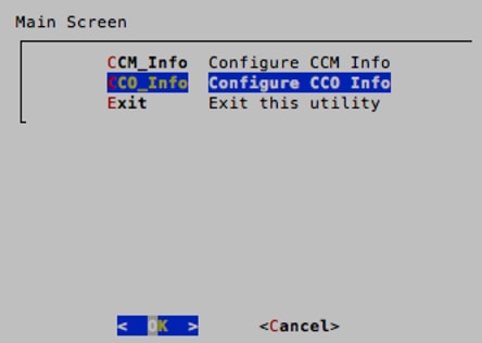

9. Select Exit to exit the utility. When prompted to restart the server, select <Yes>. This will restart Guacamole.
10. When completed with the above steps, type reboot to reload the entire VM.
Configuration Verification
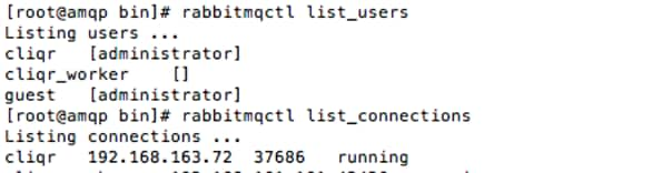
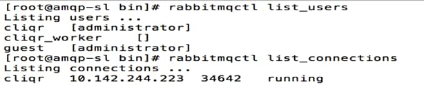
When CCO and RabbitMQ have rebooted, the following commands can be issued on RabbitMQ to verify the setup is correct.
· rabbitmqctl list_users - This will list the users associated to the CliQr domain. For now, the only user listed should be [administrator].
· rabbitmqctl list_connections - This will list the connections currently communicating with RabbitMQ. For now, the only connection listed should be cliqr with the CCO IP address.
![]() If there are any issues with the above commands, reboot the RabbitMQ VM and then the CCO When the RabbitMQ VM has completely reloaded. This will force the CCO and RabbitMQ VM to reconnect with each other.
If there are any issues with the above commands, reboot the RabbitMQ VM and then the CCO When the RabbitMQ VM has completely reloaded. This will force the CCO and RabbitMQ VM to reconnect with each other.
Repeat the above procedure to install and configure RabbitMQ and CCO for managing the VersaStack Secondary data center used for DR and Dev-Test using CloudCenter.
Steps include:
- Deployment of CCO and RabbitMQ (AMQP) OVAs
- Configuration of both CCO and RabbitMQ (AMQP) VMs
CCM Configuration
To configure the CCM server, complete the following steps:
1. Power on the CCM VM. When the VM is powered on, open a vSphere Console to access the VM. Login in with the same credentials provided for CCO and RabbitMQ.
2. As before with CCO and RabbitMQ, configure the network settings.
3. Type nmtui to open the Network Manager. Configure the IPv4 CONFIGURATION. When the IP address, gateway and DNS have been set, exit the utility and modify the hostname and hosts files with the new hostname.
4. Type cd /usr/local/osmosix/bin and then ./ccm_config_wizard.sh. This will open the Server Config Utility.
5. Press Enter to select <OK> and start the utility.
6. Use the arrow keys to select Server_Info. Input the correct DNS hostname for Public DNS and the same value for the External URL.
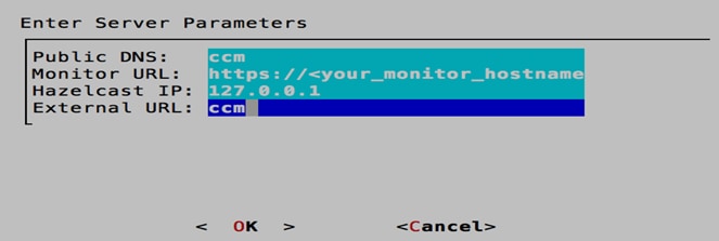
7. Use the arrow keys to select <OK> and select Yes to confirm changes.
8. Select Exit to exit the utility. When prompted to restart the server, select YES, this will restart the service.
9. When completed with the above steps, type reboot to reload the entire VM.
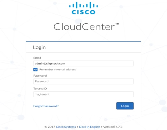
10. The CCM GUI can now be reached via the management IP address. The default username and password is admin@cliqrtech.com /cliqr.
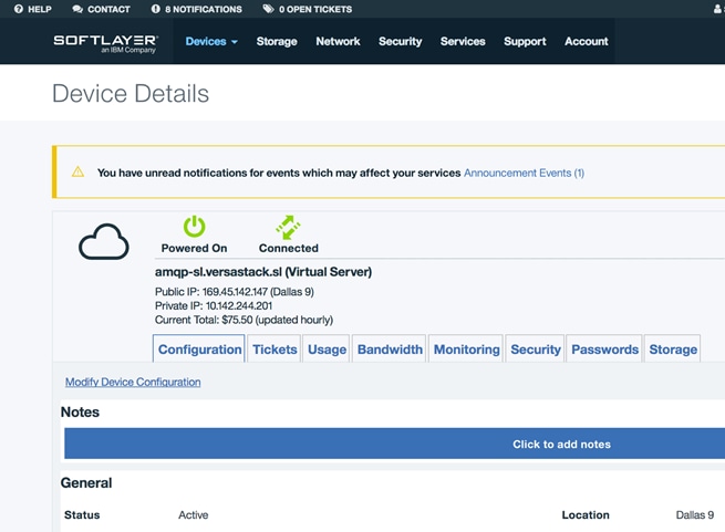
IBM Bluemix CloudCenter Installation
Cisco does not offer CloudCenter appliances for the IBM Bluemix cloud. Manual installation process needs to be followed to install the components. Two Virtual servers needs to be launched for installation of RabbitMQ (AMQP) and the CCO servers. Instances used to launch CloudCenter component VMs should minimally be 2 CPU, 4GB RAM, 50GB storage depending on the number of VMs to be managed.
To launch VMs for RabbitMQ (AMQP) and CCO installation, complete the following steps:
1. Login to http://control.softlayer.com.
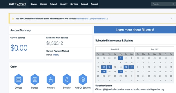
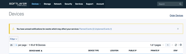
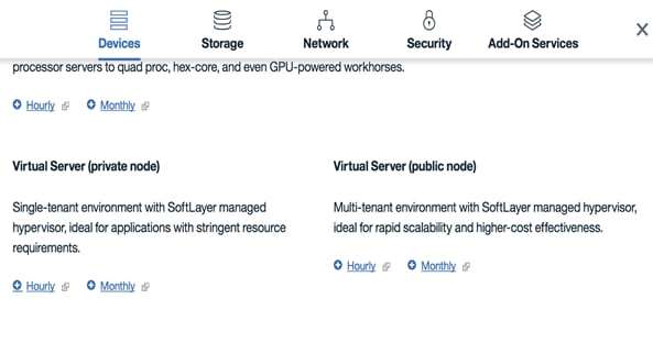
2. From the control panel, Expand Devices, select Devices list and click Order Devices.
3. Select Hourly or Monthly under Virtual Server (private node).
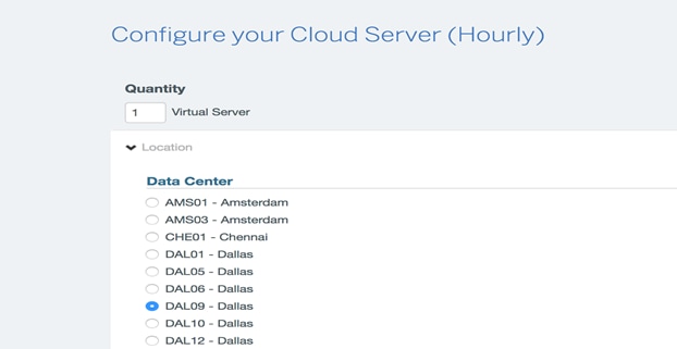
4. Select the Data Center region in Softlayer Cloud that you want to use for application deployments.
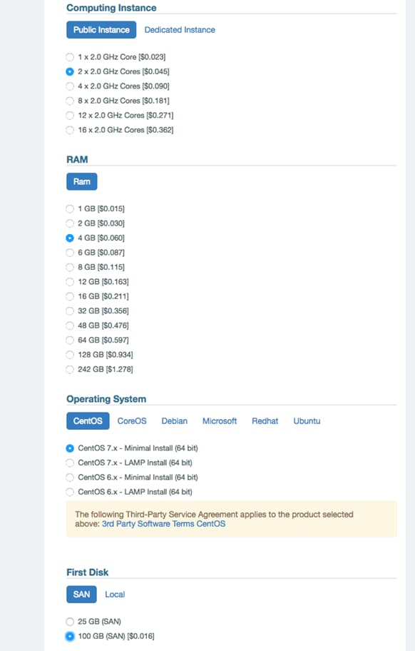
5. Choose the values for CPUs, RAM, Operating system and disk size and then click ADD TO ORDER.
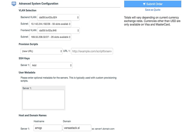
6. Select the Backend and Front end VLAN’s, the subnets and hostname. Click Submit Order to launch the VM.
7. The VM will be deployed and will be accessible after the process is complete.
8. Go to the control panel and verify that the VM is created. The password to access the VM will be provided in the control panel.
9. Repeat the above procedure to launch another VM for CCO installation.
The CloudCenter package files needs to be installed on to the deployed VMs to configure CloudCenter services. You can download installation files to a directory of your choice. The procedure provided in the CloudCenter documents, recommend using the /tmp folder as the download folder. In some cases, you may not want to use /tmp folder as the temp location as this directory may not allow files to be executed in your environment.
To install CloudCenter on systems where /tmp is set to nosuid or noexec, issue the following command before downloading the component files:
export TEMP_DIR=<any_directory_with_exec_permission>
RabbitMQ (AMQP) installation
To configure the RabbitMQ (AMQP) server at the IBM Bluemix Cloud, complete the following steps:
1. SSH into the VM instance designated for this component by using the password generated while launching the VM in Softlayer Cloud.
2. Download the following required files for this component from software.cisco.com to the /tmp folder on that VM:
· core_installer.bin
· cco-installer.jar
· conn_broker-response.xml
3. Run the core installer to setup core system components using the following commands:
sudo –i
cd /tmp
chmod 755 core_installer.bin
./ core_installer.bin centos7 softlayer rabbit
4. Remove the core_installer.bin file.
rm core_installer.bin
5. Log off and log back in as the root user to ensure JAVA Home is set.
exit
sudo -i
6. Change to the /tmp directory:
cd /tmp
7. Run the appliance installer to setup AMQP:
java -jar cco-installer.jar conn_broker-response.xml
8. Reboot the AMQP VM.
CCO installation
To configure the CCO server at the IBM Bluemix Cloud, complete the following steps:
1. SSH into the VM instance designated for this component by using the key pair that you used to launch the VM.
2. Download the following required files for this component from software.cisco.com to the /tmp folder on that VM:
· core_installer.bin
· cco-installer.jar
· cco-response.xml
3. Run the core installer to setup core system components using the following commands:
sudo –i
cd /tmp
chmod 755 core_installer.bin
./core_installer.bin centos7 softlayer cco
4. Remove the core_installer.bin file.
rm core_installer.bin
5. Log off and log back in as the root user to ensure JAVA Home is set.
exit
sudo -i
6. Change to the /tmp directory.
cd /tmp
7. Run the appliance installer to setup the CCO.
java -jar cco-installer.jar cco-response.xml
8. Reboot the CCO VM.
RabbitMQ (AMQP) and CCO Configuration at IBM Bluemix
The configuration for RabbitMQ and CCO is similar to the configuration detailed above for VersaStack VMware Clouds.
CCO Configuration
To complete the CCO configuration deployed at IBM Bluemix Cloud, complete the following steps:
1. When the CCO is powered on, login with the credentials.
2. Type cd /usr/local/osmosix/bin at the shell prompt.
3. Type ./cco_config_wizard.sh to start the Server Config Utility. Select <OK>.

4. Use the arrow keys to select AMQP_Server. Enter the private IP address of the RabbitMQ (AMQP) VM, which will be configured in the next section. Keep the default port of 5671.

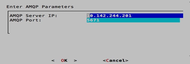
5. Press Enter and when prompted to make the changes, select <Yes> and then <OK>.
6. When back on the main selection screen of the wizard, select Guacamole. Enter the IP address of the RabbitMQ (AMQP) VM again. Keep the default ports of 7788 and 7789. Press Enter and when prompted to make the changes, select <Yes> and then <OK>.

7. Use the arrow keys to select Exit. When prompted to restart the server, select <Yes>.
8. This will only restart the tomcat service, however, a full reboot of the VM is recommended. Type reboot into the Linux command prompt.
RabbitMQ (AMQP) Configuration
To complete the RabbitMQ (AMQP) configuration deployed at IBM Bluemix Cloud, complete the following steps:
1. When the VM is rebooted after the installation, login to the VM and type cd /usr/local/osmosix/bin and the ./gua_config_wizard.sh
2. Press <OK> to enter the Server Config Utility.
3. On the main selection screen of the wizard, select CCM_Info to configure the CCM IP address. Type in the IP address of the CCM and then press Enter when prompted to make the changes, select <Yes>.

![]() Public IP address of the CCM server is used which is NATed to a private IP address at the VersaStack on-premises Private Cloud. The Private IP address of the CCM server can also be used here as we have created a Static NAT entry for the CCM private IP in the Softlayer Cloud, creation of static NAT entry at softlayer is covered in the “VersaStack Hybrid Cloud Network Configuration” section above.
Public IP address of the CCM server is used which is NATed to a private IP address at the VersaStack on-premises Private Cloud. The Private IP address of the CCM server can also be used here as we have created a Static NAT entry for the CCM private IP in the Softlayer Cloud, creation of static NAT entry at softlayer is covered in the “VersaStack Hybrid Cloud Network Configuration” section above.
4. When back on the main selection screen of the wizard, select CCO_Info to configure the CCO IP address. Type in the IP address of the CCO and then press Enter when prompted to make the changes, select <Yes>.
5. Select Exit to exit the utility. When prompted to restart the server, select <Yes>. This will restart Guacamole.
6. When completed with the above steps, type reboot to reload the entire VM.
Configuration Verification
When CCO and RabbitMQ have rebooted, the following commands can be issued on RabbitMQ to verify the setup is correct.
· rabbitmqctl list_users - This will list the users associated to the CliQr domain. For now, the only user listed should be [administrator].
· rabbitmqctl list_connections - This will list the connections currently communicating with RabbitMQ. For now, the only connection listed should be cliqr with the CCO IP address.
![]() The screenshot shown below show more items since it was taken later during the deployment process.
The screenshot shown below show more items since it was taken later during the deployment process.
![]() If there are any issues with the above commands, reboot the RabbitMQ VM and then the CCO when the RabbitMQ VM has completely reloaded. This will force the CCO and RabbitVM to reconnect with each other.
If there are any issues with the above commands, reboot the RabbitMQ VM and then the CCO when the RabbitMQ VM has completely reloaded. This will force the CCO and RabbitVM to reconnect with each other.
Configure and Setup CloudCenter Manager
The CCM is the central point of management for CloudCenter. The CCM communicates with the CCOs to deploy applications to various different cloud environments.
In CloudCenter, Clouds are added and managed by the CCM. In this solution, there will be three cloud environments VersaStack Private cloud, VersaStack DR/Dev-Test Cloud and the IBM Bluemix Public cloud. Regardless of the cloud type, each target Cloud requires a CCO.
A Cloud Region refers to single Public Cloud region, Private Virtualized Datacenter, or Private Cloud supported by CloudCenter. Each cloud region is identified in the CCM UI when you configure clouds.
VersaStack Private Cloud Configuration
To configure VersaStack Cloud, complete the followings steps:
1. Open a web browser and navigate to your CloudCenter Manager GUI using the IP address or FQDN name.
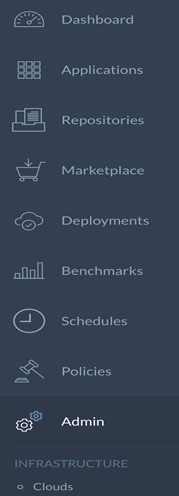
2. In the left-hand pane, click the double >> to expand the navigation tray. Select the Admin section, as indicated by the pair of cogs/gears.
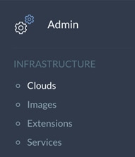
3. Select Clouds under Infrastructure.
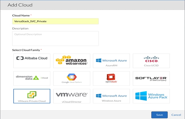
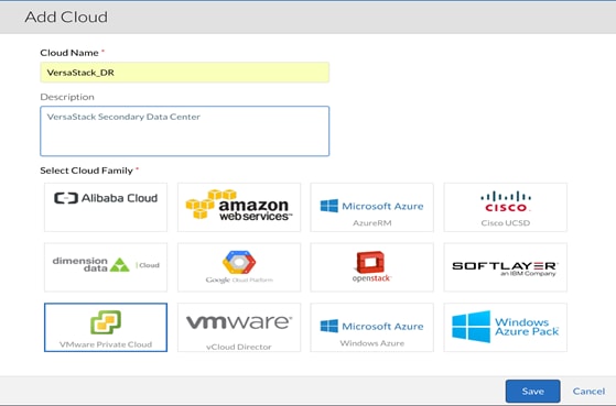
4. In the main-panel, click Add Cloud to add a managed Cloud.
5. The cloud can be named anything; however, it is recommended to base the name on the type of the managed cloud. Our cloud is named <VersaStack_SVC_Private>. From the list below, select VMware Private Cloud and click Save.
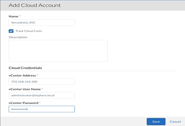
6. Next, there needs to be a Cloud Account associated to the Cloud.
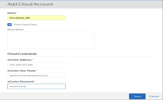
7. In the main-panel, select Add Cloud Account.
8. When again, the name can be anything as dictated by the environment. Since this is vCenter, the options presented to the user are for a VMware environment. Enter the vCenter Address, vCenter User Name and vCenter Password.
9. When completed, click Save.
10. In the main-panel of the CCM GUI, the Cloud Account should be listed under the VMware Cloud. The next step will be to add Cloud Regions.
Cloud Regions – VersaStack Private Cloud
To link the CCO (previously deployed) to the CCM, in our VMware Private Cloud, complete the following steps:
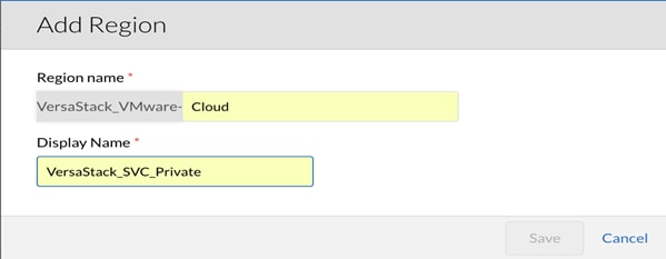
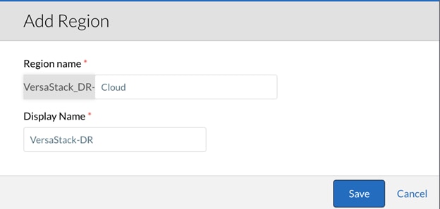
1. Navigate back to the Clouds section in the CloudCenter GUI. Click the <VersaStack_VMware> cloud and then select Add Region in the main-panel.
2. In the pop-up box, name your Region as necessary and complete the Display Name to match the Region name. Our Region is called <VersaStack_SVC_Private> to indicate this Region is VersaStack Private Cloud.
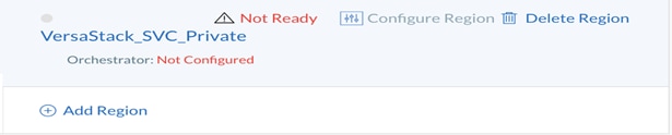
3. When the region has been created, click Configure Region underneath <VMware_SVC_Private> to complete the configuration of the Cloud Region.
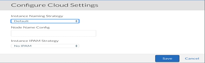
4. When the main-panel updates, click Edit Cloud Settings and select Default for Instance Naming Strategy and No IPAM for IPAM Strategy.
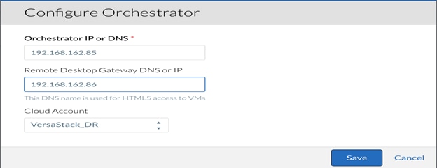
5. Click Configure Orchestrator. This is where the Region is associated with the right Orchestrator.

6. Enter the IP address for the Orchestrator. The Remote Desktop Gateway is the IP address of the RabbitMQ VM where Guacamole will handle any remote connections to the applications. Finally, the Cloud Account field will associate the Region with the necessary credentials and addresses to provision the application profile workflows.
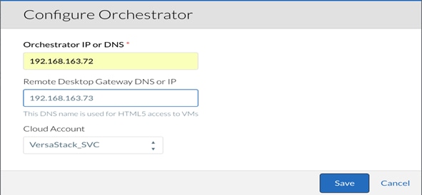
7. When complete, click Save.
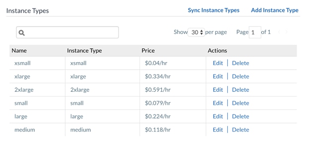
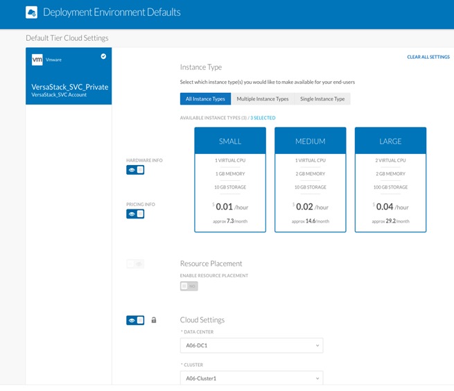
Instance Types
When you deploy an Application Profile, the Instance Type determines the virtual hardware for the application VMs. Each Instance Type offers different compute, memory, and storage capabilities and are grouped in instance families based on these capabilities. Instance types give you the flexibility to choose the appropriate mix of resources for your applications.
The selection of an instance type is based on the requirements of the application or software that you plan to run in your Cloud Region. For example, many public clouds provide a wide selection of instance types optimized to fit different use cases. Each instance type includes one or more instance sizes, allowing you to scale your resources to the requirements of your target workload.
However, in a VMware Private Cloud, Instance Types are not a configurable option or recognized construct. Regardless, because there may be a need to deploy applications of various sizes and capabilities, the Instance Types in CloudCenter will be used to determine the VM's virtual hardware.
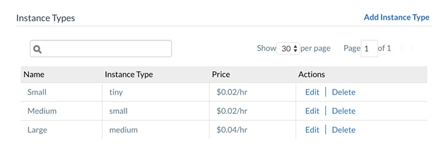
For the purposes of this document, we are going to create 3 Instance Types - Small, Medium and Large. The variables for each Instance Type will scale accordingly.
| Instance Type |
Price (/hr) |
CPU |
Architecture |
Name |
RAM (MB) |
NICs |
Local Storage (GB) |
| Small |
$.01 |
1 |
Both |
Small |
1024 |
1 |
10 |
| Medium |
$.02 |
2 |
Both |
Medium |
2048 |
1 |
20 |
| Large |
$.04 |
4 |
Both |
Large |
4096 |
1 |
40 |
8. Click Add Instance Type to configure an Instance for this Region.
9. Name the first Instance Type Small.
![]() Each Instance Type is associated with a Price. While this price may hold monetary value in a Public Cloud, where the computing and storage is being provided as a service, the cost may be meaningless in a Private Cloud.
Each Instance Type is associated with a Price. While this price may hold monetary value in a Public Cloud, where the computing and storage is being provided as a service, the cost may be meaningless in a Private Cloud.
![]() It is recommended to change the Architecture from 32 bit to Both. In most circumstances, there is no difference in cost between a 32 bit and 64 bit instance. This change will minimize the number of instances needed to be maintained.
It is recommended to change the Architecture from 32 bit to Both. In most circumstances, there is no difference in cost between a 32 bit and 64 bit instance. This change will minimize the number of instances needed to be maintained.
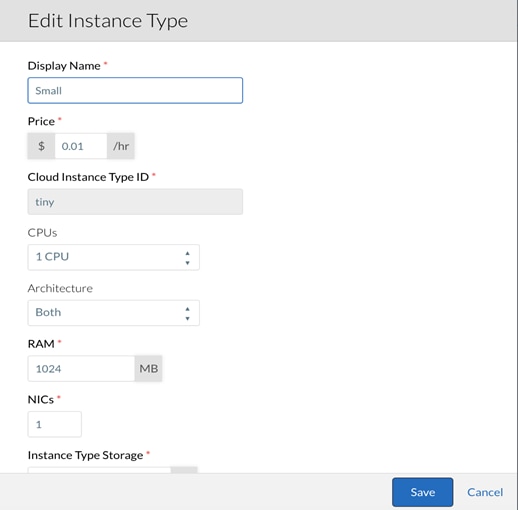
10. When the fields have been completed as indicated by the table above, click Save.
11. Repeat the above steps and create the Medium and Large Instance Types.
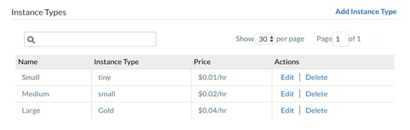
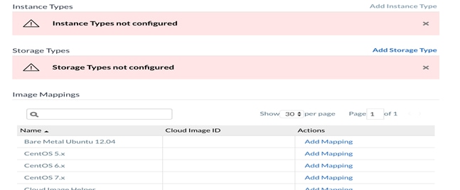
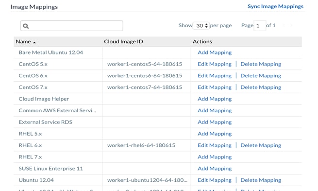
Image Mappings
CloudCenter uses the logical image (Image ID) to build an application profile. The logical images can be:
· CloudCenter provided images (system image)
· Customer created images (custom image)
Each logical image has a corresponding physical (mapping) image on each cloud. The platform or tenant administrator references these logical images and makes them available to permitted users. An image library refers to a collection of images listed in the Images tab in the CCM UI.
In the case of VMware Private Cloud, the image mappings will reference a specific folder in the Datacenter where the VM templates or Snapshots will be stored.
Before the images can be mapped in CCM, a special folder needs to be created in the appropriate vSphere Datacenter.
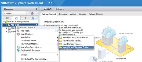
To create a folder in the vSphere Datacenter, complete the following steps:
1. Using vCenter, navigate to the Datacenter and right-click the parent object and select New VM and Template Folder under the All vCenter Actions option of the menu. The folder MUST be named CliqrTemplates. This folder will contain all the gold images for the applications.
2. Download the worker image for CentOS 6.x from software.cisco.com:
a. The OVA needs to be deployed in the vSphere environment.
b. A Snapshot needs to be created. The VM is called CentOS6 and the Snapshot is named snap1.
![]() When the VM is deployed, make sure it is in the CliqrTemplates folder.
When the VM is deployed, make sure it is in the CliqrTemplates folder.
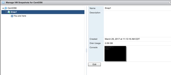
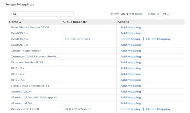
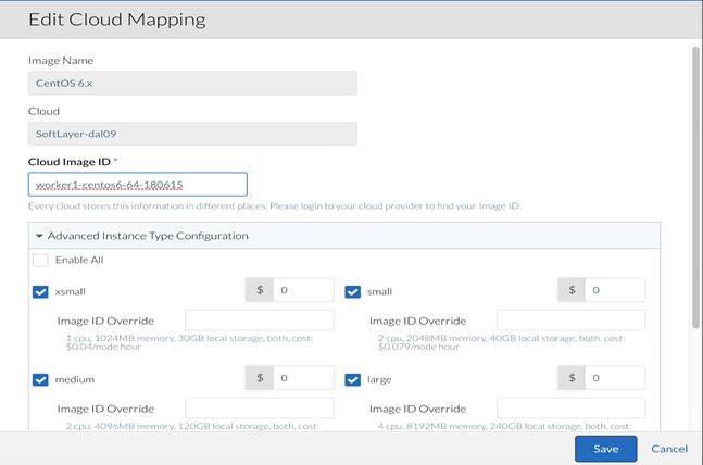
3. When the OVA finish deploying, the Snapshot of the VM needs to be referenced in the CCM. Near the bottom of the Cloud Region configuration, click Add Mapping for CentOS 6.x.
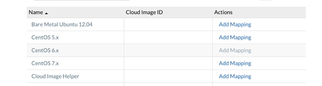
4. In the pop-up window, enter the Cloud Image ID. In VMware Clouds, the Cloud Image ID is <VM name> / <snapshot name>. Expand Advanced Instance Type Configuration and select Enable All.
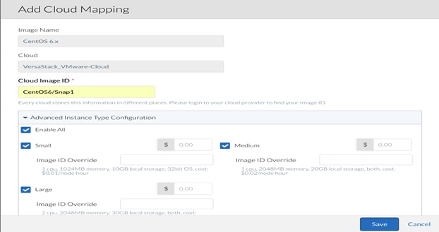
5. Click Save to complete the image mapping for CentOS 6.
![]() Worker image for windows is not available from cisco.com.
Worker image for windows is not available from cisco.com.
To install CloudCenter Tools on a Windows image, complete the following steps:
1. Contact CloudCenter Support to obtain the installer package (cliqr_installer.exe).
2. A Windows 2012 VM is leveraged on VersaStack to create windows custom image.
3. Access the VM using console or RDP to the VM.
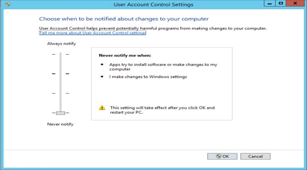
4. Configure and save the User Account Control Level to Never Notify.
5. CloudCenter requires Powershell 4.0. Verify that you are running this version of Powershell:
PS C:\> $PSVersionTable.PSVersion
Major Minor Build Revision
----- ----- ----- --------
4 0 -1 -1
6. In the Powershell command line window, issue the command to bypass the Powershell ExecutionPolicy.
Set-ExecutionPolicy -ExecutionPolicy Bypass
7. Verify that the C:\PROGRA~1 path is resolvable to C:\Program Files.
dir "C:\PROGRA~1"
8. Otherwise, you must create the corresponding link:
mklink /J "C:\PROGRA~1" "C:\Program Files"
9. Download CloudCenter Tools (cliqr_installer.exe).
10. Go to the command prompt window and run the downloaded file:
C:\Downloads cliqr_installer.exe /CLOUDTYPE=vmware /CLOUDREGION=default
11. Run the Installer. You may add the IIS installation (depends on your deployment).
12. Create a snapshot of the image from your VMware console.
13. After creating the snapshot, include the Image ID in the CloudCenter logical image (CCM UI > Admin > Images > Manage Cloud Mapping > Edit Mapping).

14. Click Save to complete cloud region configuration.
VersaStack DR Cloud Configuration
Repeat the steps detailed in the section VersaStack Private Cloud Configuration to Configure the VersaStack DR/Dev-Test environment in the CloudCenter.
To configure VersaStack DR Cloud, complete the following steps:
1. Adding the VersaStack DR/Dev-Test Cloud in CCM.
2. Add Cloud Account for the newly added cloud.
3. Add Cloud Region in CloudCenter Manager.
4. Add and Configure CloudCenter Orchestrator.
5. Create Instance Types.
6. Create Image mappings for CentOS and Windows Operating Systems.
IBM Bluemix Public Cloud Configuration
IBM Bluemix Cloud requires the installation of two VMs through a manual installation:
· CloudCenter Orchestrator (CCO)
· RabbitMQ (AMQP)
Before mapping a SoftLayer cloud on the CloudCenter platform, verify the following SoftLayer requirements:
· A valid SoftLayer PORTAL account.
· SoftLayer Account Name: The exact name displayed in the Username column in the SoftLayer Portal's Users page. Copy the required Username and paste it in the CloudCenter CCM UI as specified during the Configuration Process identified below.
· SoftLayer Account API Key: This is the API key for this user's account: If you do not have an API key for this account, retrieve the API key at this point from the User Profile.
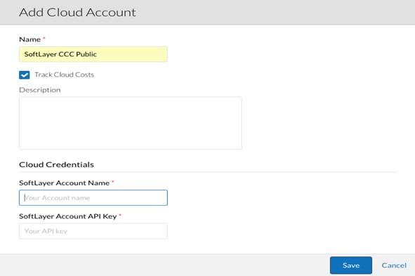
To Setup CloudCenter using components for IBM Bluemix Public Cloud, complete the following steps:
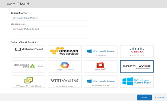
1. Access the CCM UI > Admin > Clouds > Add Cloud in the CCM UI main menu.
2. Select the SoftLayer an IBM Company option, provide a Name and Description for this cloud, and click Save.
3. Locate the newly-added cloud and click the Add Cloud Account link. The Add Cloud Account pop-up displays: Assign a new cloud name.
4. Add the Cloud Credentials associated with your SoftLayer account and click Save.
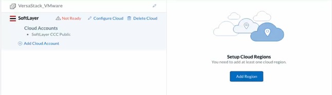
Cloud Regions – VersaStack Public Cloud
In Softlayer Cloud, the CCO previously deployed will be linked to the CCM. To configure the cloud regions, complete the following steps:
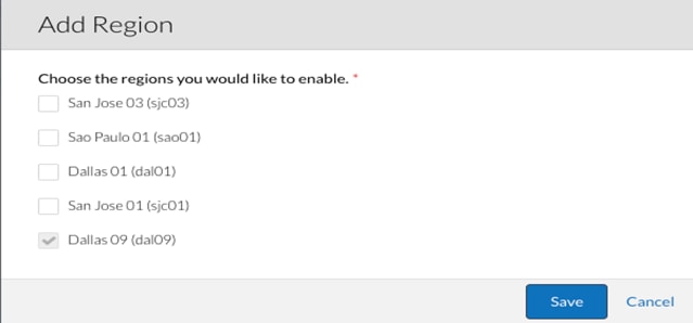
1. Navigate back to the Clouds section in the CloudCenter GUI. Click the Softlayer CCC Public cloud and then select Add Region in the main-panel.
2. In the pop-up box, select Dallas 09 (dal09) as the cloud data center region.
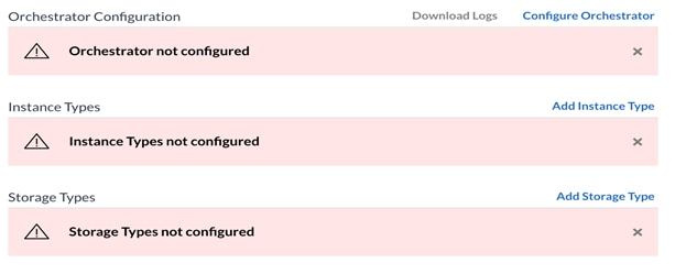
3. When the region has been created, click Configure Region underneath Softlayer Public Cloud to complete the configuration of the Cloud Region.
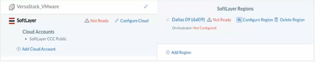
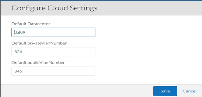
4. Select the Regions tab to configure the cloud settings.
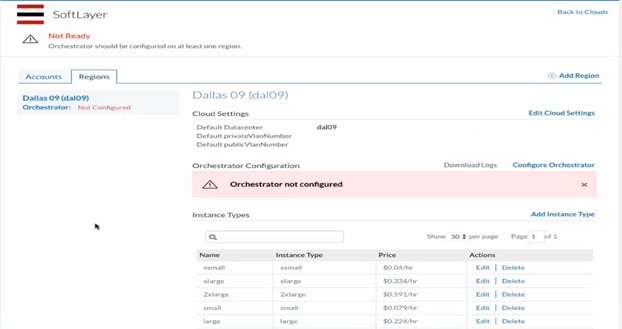
5. Click Edit Cloud Settings to update the Softlayer cloud settings for the region, specify the Default privateVlannumber and Default publicVlannumber that will be used when CloudCenter instance is launched and Click Save.
6. Click Configure Orchestrator. This is where the Region is associated with the correct Orchestrator.
7. Enter the IP address for the Orchestrator. The Remote Desktop Gateway is the IP address of the RabbitMQ VM where Guacamole will handle any remote connections to the applications. Finally, the Cloud Account field will associate the Region with the necessary credentials and addresses to provision the application profile workflows.
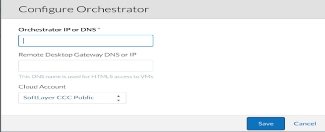
8. When complete, click Save.
Instance Types and Image Mappings
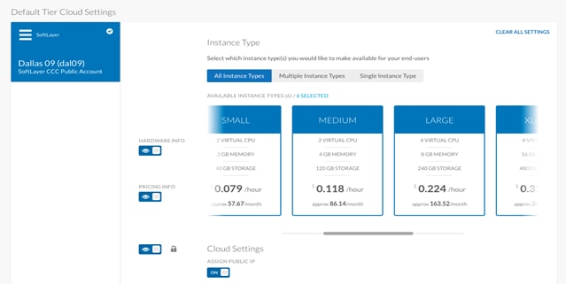
When you deploy an Application Profile, the Instance Type determines the virtual hardware for the application VMs. Each Instance Type offers different compute, memory, and storage capabilities and are grouped in instance families based on these capabilities. Instance types give you the flexibility to choose the appropriate mix of resources for your applications.
IBM Softlayer provides a wide selection of instance types optimized to fit different use cases. Each instance type includes one or more instance sizes, allowing you to scale your resources to the requirements of your target workload.
The Instance Types, the Storage Types, and the Image Maps sections are automatically populated as soon as you add the region.
![]() Each Instance Type is associated with a Price. While this price may hold monetary value in a Public Cloud, where the computing and storage is being provided as a service.
Each Instance Type is associated with a Price. While this price may hold monetary value in a Public Cloud, where the computing and storage is being provided as a service.
1. The images have to be manually deployed in the Softlayer cloud and should match the image id populated in the CCM GUI:
2. Click Edit mapping under Actions pane for the CentOS 6.x image. Make a note of the image id populated, which will be used later in the procedure to name the image in Softlayer cloud.
3. Click Save.
4. Login to Softlayer portal.
5. Order a Linux (CentOS6) virtual server from the devices list by providing the required values.
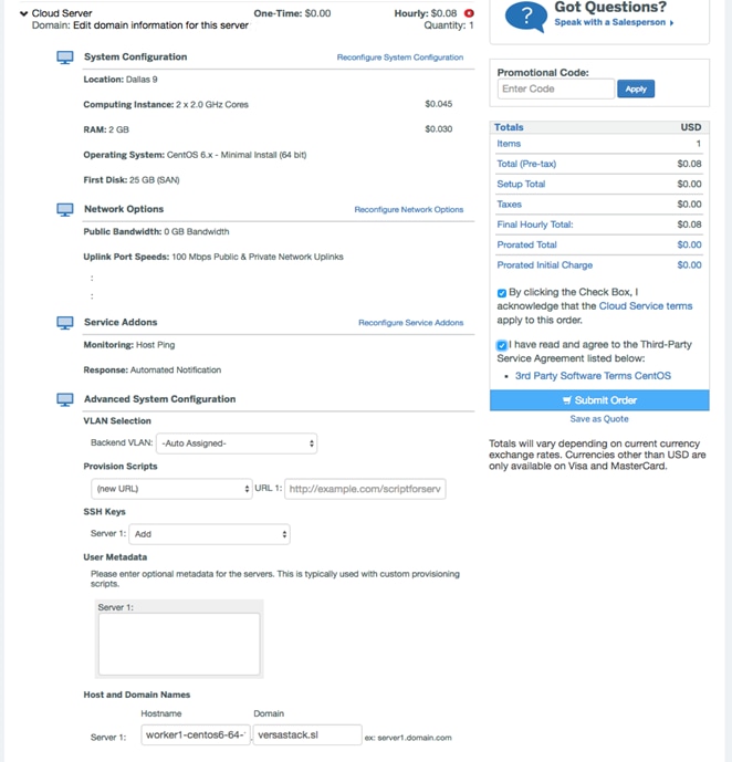
6. When the virtual server is provisioned, install the CloudCenter tools to create CloudCenter-enabled image. Follow the steps detailed above to create other operating system images as required.
To install CloudCenter tools (see Key Components) on a Linux image, complete the following steps:
1. Contact CloudCenter Support to obtain the installer binary and the path. Download the installer package (worker_installer.bin) to the CCM VM’s /tmp folder.
2. SSH into the application VM instance using the key pair/password that you used to launch the VM.
3. Run the following commands to install CloudCenter Tools:
sudo –i
cd /tmp
4. Download the installer package to the application VM’s /tmp folder.
5. Change permissions and use the application VM (worker) installer file to install CloudCenter Tools:
chmod 755 worker_installer.bin
./worker_installer.bin centos6 softlayer worker1
6. Clean up and exit the VM instance:
rm worker_installer.bin
rm ~/.ssh/authorized_keys
exit
7. After you run the installer commands, the installation results are displayed on the screen as follows:
· Successful scenarios: Identifies a list of successfully installed components in green text.
· Failure scenarios: Provides a path to the log file that provides details of each failure.
8. After successful installation, create the image using the configured Virtual server.
9. Access the virtual server from softlayer control panel > Devices > Devices List and select the virtual server by clicking the server name.

10. Click the Actions tab available at the right most corner for this virtual server and select Create Image Template.
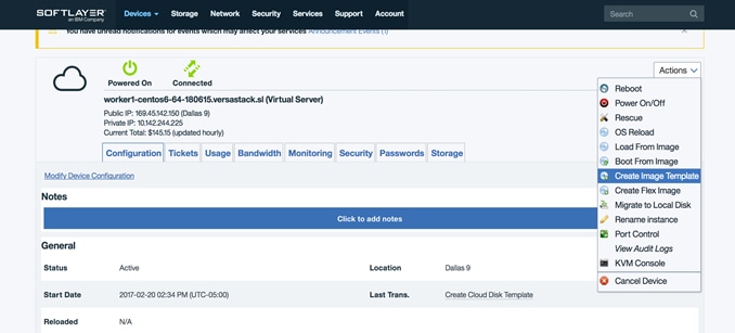
11. Input the device name matching the image id for this specific operating system from the CCM.
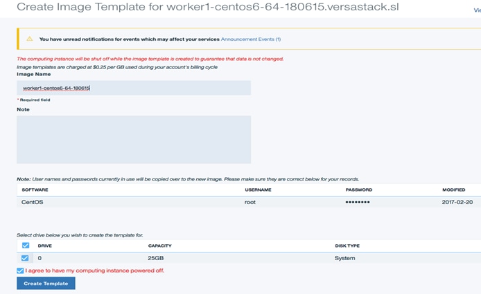
12. Click Create Template to create the image.

Usage Plans and Contracts
Usage Plans are agreements determined by the administrator and assigned to a user to determine the capacity or allowed usage for that user.
Every CloudCenter plan requires a Contract. When users sign up with CloudCenter, you can enforce the user to accept a Terms of Contract agreement that dictates how long this agreement should last. CloudCenter does not automatically renew the contract when the contract ends. When a contract ends, users have the option to switch to another contract.
The root or tenant admin can create contract, bundles, and plans. The tenant admin can belong to an enterprise or to CloudCenter depending on the deployment. CloudCenter generally refers to both as the administrator (or admin).
![]() In a VMware Private Cloud, the idea of Usage Plans and Contracts may not be necessary. However, because of the way CloudCenter works, both of these constructs are required before any applications can be deployed.
In a VMware Private Cloud, the idea of Usage Plans and Contracts may not be necessary. However, because of the way CloudCenter works, both of these constructs are required before any applications can be deployed.
Usage Plans
1. Login to CCM UI using the CCM IP address or the FQDN name.
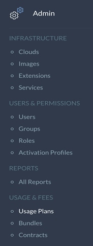
2. In the left-hand pane, click the double >> to expand the navigation tray. Select the Admin section, and then click Usage Plans under Usage and Fees.
3. In the main-panel, click Create Usage Plan.
4. Name the Usage Plan as desired and select a Plan Type. The Plan Type will determine how usage is measured. In this case, we selected VM Subscription and set the Maximum Running VMs to 100. This will allow us to run 100 VMs concurrently before hitting a usage restriction.
5. The Plan Fees section will outline any costs that are associated with the Usage Plan. Our plan will "cost" $100 /per month. Also, include some additional fees for Overage. Overages occur any time the workload exceeds the Usage Plans. For example, this would be any number of VMs deployed AFTER the first 100. Set a Limit of 10 and set the Overage Rate for $10 with a One-time Fee of $50.
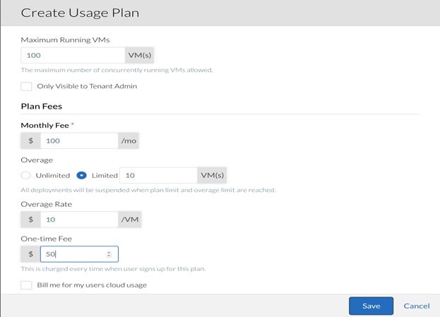
6. Click Save to continue.
7. In the left-hand pane, click the double >> to expand the navigation tray. Select the Admin section, and then click Contracts under Usage and Fees.
8. In the main-panel, click Create Contract.
9. Name the Contract as desired and then specify a Length in months. The Terms are any rules, guidelines, expectations, etc. associated with the Contract.
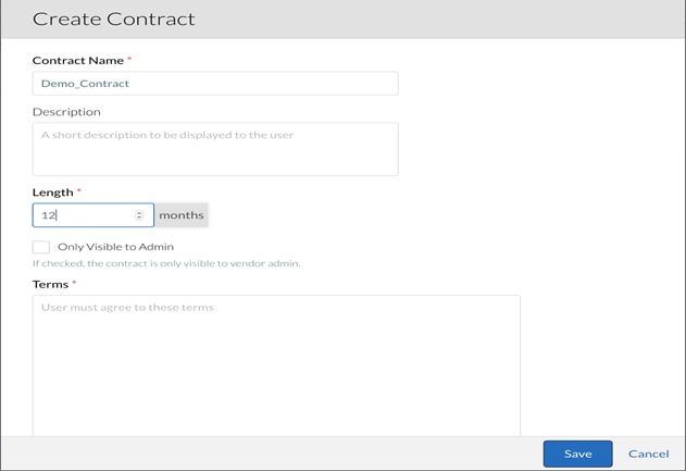
10. Click Save to continue.
Usage Plan and Contract Association
When the Usage Plan and Contract have been created, they need to be assigned to a User. In CloudCenter, the User is the person who use the CCM to deploy applications to the CCO. In our environment, the only User created is Cliqr Admin. The Cliqr Admin User will need to have access to the Usage Plan and Contract to create and deploy Application Profiles.
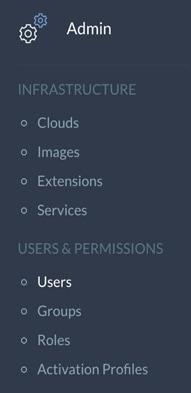
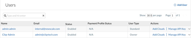
1. In the left-hand pane, click the double >> to expand the navigation tray. Select the Admin section, and then click Users under Users and Permissions.
2. In the main-panel, click the small grey arrow at the end of the row for the Cliqr Admin User and select Manage Plan from the drop-down.
3. In the pop-up window, select the previously created Usage Plan and Contract from the drop-downs.
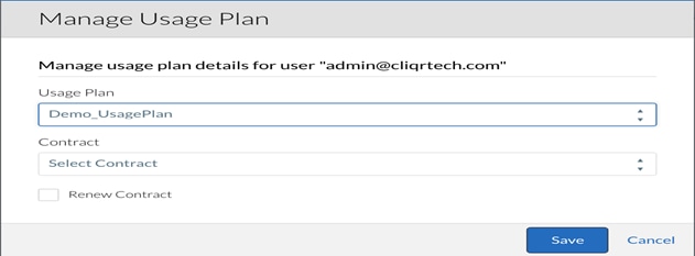
4. Click Save to continue.
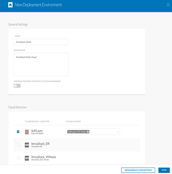
Deployment Environments
Deployment Environments contain one or more associated cloud regions and cloud accounts. These environments are set aside for specific deployment needs. Users deploy applications to Deployment Environments, and deployment environments can be shared with multiple users.
For example, a Dev Development Environment could be associated with a development cloud and a Prod Deployment Environment could be associated with a production grade high-performance cloud. Users on a development team would have the ability to deploy only to the Development environment and users on an operations team would have the ability to deploy only to the Production environment.
The following steps walk you through creation of three deployment environments: VersaStack Private Cloud, VersaStack Secondary DR/Dev-Test Cloud and IBM Bluemix Public Cloud.
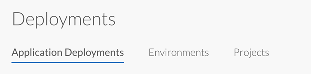
1. In the left-hand pane, click the double >> to expand the navigation tray. Select the Deployments section.
2. In the main-panel, select Environments and then New Environment.
3. Name the environment as desired and then associate it with a Cloud Region and Cloud Account.
4. The first Deployment Environment will be called <VersaStack_Private> and will be associated with the <VersaStack_SVC_Private> Cloud Region and the <VMware_SVC> Cloud Account.
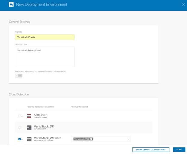
5. When completed, click Done.
6. Repeat the steps above to create a second Deployment Environment for VersaStack Secondary data center. However, this time, the cloud should be name <VersaStack_DR> and will use Cloud Region and Cloud Account; <VersaStack-DR > and <VersaStack_DR>.
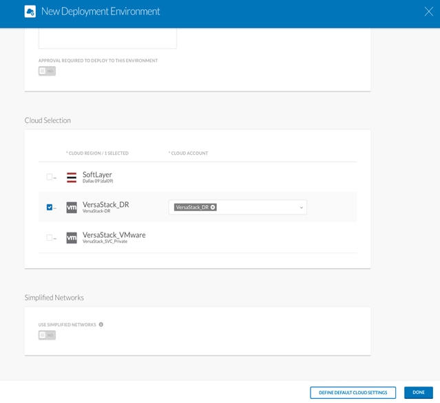
7. When completed, click Done.
8. Repeat the steps above to create a third Deployment Environment for IBM Bluemix Public Cloud.
9. When completed, click Done.
10. Repeat the steps above to optionally create another Deployment Environment for VersaStack Hybrid that includes the VersaStack Private data center and the Softlayer Public Cloud for stretched application deployments.
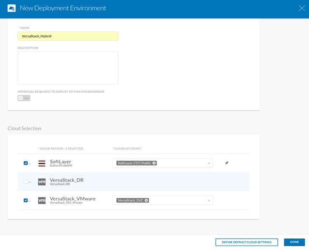
11. When completed, click Done.
12. When the Deployment Environment has been saved, click the drop-down in the Actions column and select Edit.
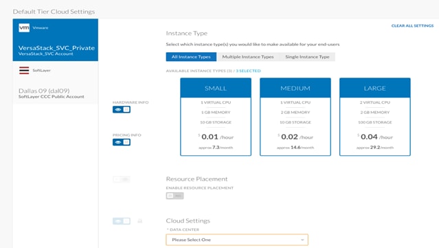
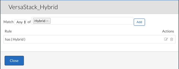
![]() The above picture displays VersaStack_Hybrid deployment environment that consists of VersaStack Private and the IBM Bluemix Public Clouds, this is optional and can be created following the above procedure if there is a need to deploy stretched applications across Private and Public Clouds.
The above picture displays VersaStack_Hybrid deployment environment that consists of VersaStack Private and the IBM Bluemix Public Clouds, this is optional and can be created following the above procedure if there is a need to deploy stretched applications across Private and Public Clouds.
13. When the pop-up appears, click DEFINE DEFAULT CLOUD SETTINGS at the bottom of the page.
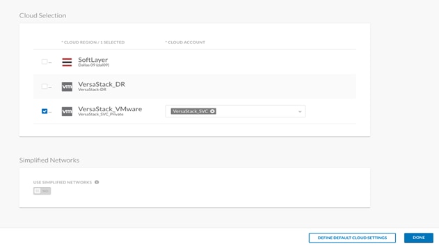
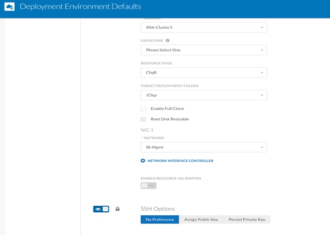
14. In the pop-up window, select the defaults for deployments being made in that specific environment. This data is being polled from vCenter and should match the physical deployment environment.
15. Repeat the steps above to define default cloud settings for Softlayer.
16. Click Done and continue.
17. Repeat the steps to define default cloud settings for <VersaStack_DR>

18. Click Done and continue.
19. Repeat the steps above again to define the default cloud settings for Hybrid cloud.
20. Click Done and then Save to complete the setup.
Governance
Cisco CloudCenter administrators can control user actions with tag-based automation that simplifies users’ placement, deployment, and run-time decisions.
The administrator identifies tags with easily understandable labels such as Dev, Prod, etc. The administrator specifies the rules to be associated with each tag; for example, rules that specify the selection of the appropriate deployment environment, firewall rules, or aging-policy rules. When users deploy an application profile, they simply add the required tags. They do not have to understand the underlying rules and policies.
This document details using the system tags to enforce governance for application placement decisions and will create a sample aging policy.
Adding a System Tag
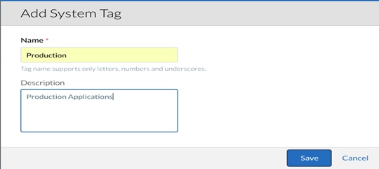
When you add a system tag, you create a new tag based on configuration settings that you make. To add a system tag, complete the following steps:
1. On the System Tags page under Admin > GOVERNANCE, click the Add System Tag link. The Add System Tag page displays.
2. In the Name field, enter <Production>.
3. (Optional) In the Description field, enter a brief description of the system tag.
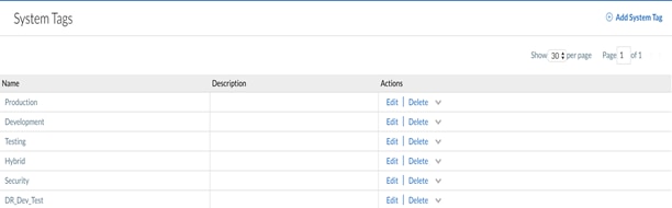
4. Click the Save button.
5. Follow the above procedure to create additional tags named <Development>, <Testing>, <Hybrid>, <DR_Dev_Test>.
Enforce Governance rules
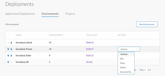
1. Enable rules-based governance by clicking the ON toggle button on the Governance Rules page
2. Go to Deployments on the main page and click the Environments tab. The deployment environments will get displayed.

3. Click the far-right side under ACTIONS column for each deployment environment and select Associate Rules.
4. Select the respective tag created earlier for each deployment environment and click Add and click Close to associate tags with the deployment environments.
5. The table below lists the tags associated with each deployment environment:
| TAG |
Deployment Environment |
| Production |
VersaStack_Private |
| Development |
VersaStack_Public |
| Testing |
VersaStack_Public |
| Hybrid |
VersaStack_Hybrid |
| DR_Dev_Test |
VersaStack_DR |
Creating Policies
A policy causes the CloudCenter platform to perform configured activities when certain events or conditions occur. For example, a policy could cause the CloudCenter platform to send an email alert message to a designated administrator if a cloud goes down. You use the Policies window to configure the following types of policies:
· Action Policy – Causes the CloudCenter platform to send an email message, invoke a web service, execute a command or script, or perform any number and combination of these activities when a designated event occurs
· Scaling Policies – Causes the CloudCenter platform to increase or decrease VM resources for each application deployment tier that is associated with the policy when one or more designated conditions occur
· Aging Policies – Causes the CloudCenter platform to suspend and optionally terminate each application deployment that is associated with the policy after the deployment has been running for a designated period of time term
As an example, you will create an Aging policy that will terminate the application deployments after two hours of runtime.
To add an aging policy, complete the following steps:
1. On the Aging Policies page, click the Add Aging Policy link.
2. In the Name field, enter <AutoAging2Hour>.
3. (Optional) In the Description field, enter a brief description of the system tag.
4. In the Automatically suspend deployment in fields, choose 2 hours as time length in the left field and time unit in the right field.
5. Check terminate deployment if you want to terminate the application deployment.

6. Click the Save button to create the policy.
7. Click the tag icon on the right-hand side corresponding to the policy name to associate tags.
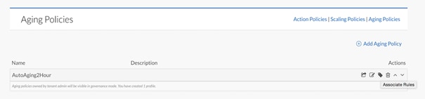
8. We will select <Development> tag, click Add and Click Close.
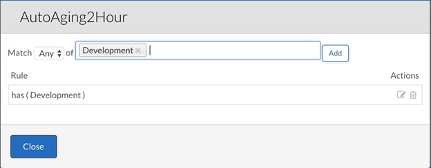
9. With this policy in place, any application deployed in the Softlayer Public Cloud will get suspended and/or terminated after 2 hours based on the options selected.
When the Deployment Environment has been created, we are ready to deploy Applications to our Cloud Regions. Before the Applications can be deployed however, they need to be modeled.
Model Applications
To create a sample application profile for a web server, complete the following steps.
![]() The OpenCart application profile used to validate the solution has been imported in to CloudCenter and the modelling of OpenCart application is not covered as part of this procedure.
The OpenCart application profile used to validate the solution has been imported in to CloudCenter and the modelling of OpenCart application is not covered as part of this procedure.
1. Login to CloudCenter Manager, In the left-hand pane, click the double >> to expand the navigation tray. Select the Applications section.
2. In the main-panel, pre-created Application Profiles will be displayed if any exists. To create a new one, click Model.

3. When the main-panel refreshes with a list of templates, select N-Tier Execution.
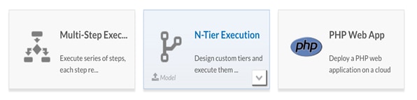
4. The main-panel will now display the modeling tool for creating Application Profiles. The tool defaults to the Topology Modeler tab.
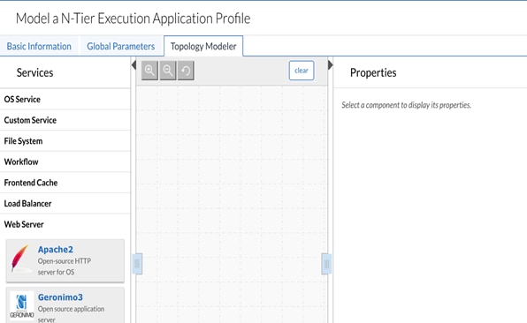
5. In the tool, on the left-hand side, select OS Service and then drag CentOS to the canvas of the tool.

6. On the right, there will be a list of options specific to that Application Profile object. For now, the only section that "needs" to be modified is the Firewall rules. In order to test this feature, add two rules with the following properties: TCP, 22, 22, 0.0.0.0/0 and TCP, 80, 80, 0.0.0.0/0.
7. Next, switch to the Basic Information tab of the Application Profile tool (upper left-hand corner of the tool).
8. Name the Application Profile Web App. The Version of the Web App is the version of the Application Profile. This allows for users to deploy different versions of the same Application Profile. In this case, the Version is 1.0.
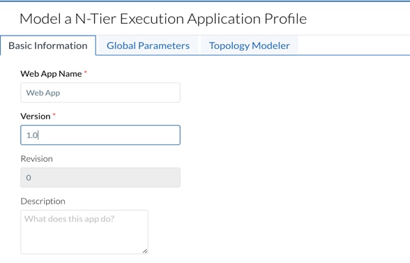
9. The rest of the Basic Information tab will use the default settings, click Save as App to save the application profile.
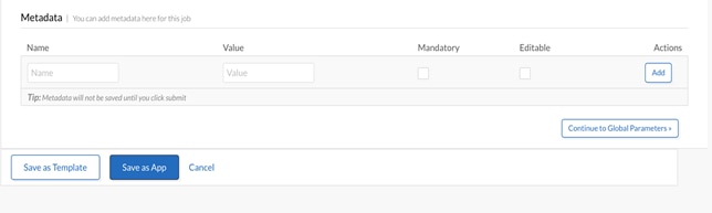
10. Assuming everything is completed correctly, the application can now be deployed. In the left-hand pane, click the double >> to expand the navigation tray. Select the Applications section.
11. In the main-panel, click your Application Profile to begin the deployment process.
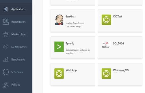
![]() The procedure detailed above is provided only as a reference; applications will have specific software requirements and all the required packages needs to be made available to the application profile along with all dependencies.
The procedure detailed above is provided only as a reference; applications will have specific software requirements and all the required packages needs to be made available to the application profile along with all dependencies.
Deploy OpenCart Application
The OpenCart application can be modeled or imported in to the CloudCenter. The modeling approach described above is best for users who have detailed knowledge of the application.
The import approach is best for users who do not have detailed knowledge of the application and related components. The OpenCart application profile used for validating the solution has been imported into the Cisco CloudCenter manager.
Artifact Repository
Typically, enterprises maintain application packages, data, and scripts in multiple repositories of their choice. Use the Artifact Repository to attach your own external repository to store and access your files. CloudCenter provides a Repositories tab in the CCM UI for this purpose.
1. Login to CloudCenter Manager. In the left-hand pane, click the double >> to expand the navigation tray. Select the Repositories section.
2. In the main-panel, available repositories will be displayed if any exists. To create a new one, click Add Repository.

3. Provide a name <CliqrDemoRepo> for the Repository and the hostname with the URL that hosts OpenCart binaries and scripts.
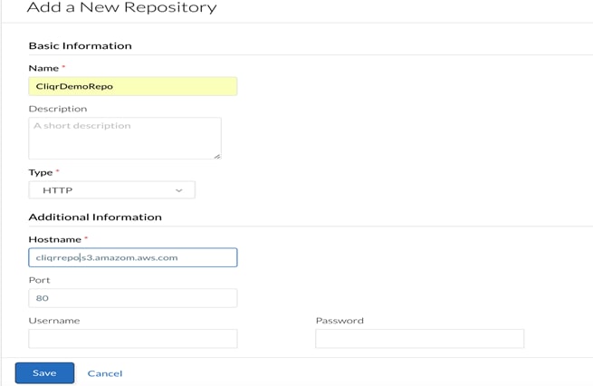
4. In the left-hand pane, click the double >> to expand the navigation tray. Select the Applications section.
5. In the main-panel, pre-created Application Profiles will be displayed if any exists. To create a new one, click Import and select Profile Package.

6. Click Upload Profile Package in the pop-up window.
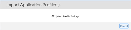
7. Select the ZIP file for the OpenCart application. The application profile has been pre-downloaded to our local PC.

8. CloudCenter validates the format and displays the application in the Applications tab. The imported profile is now available for deployment.
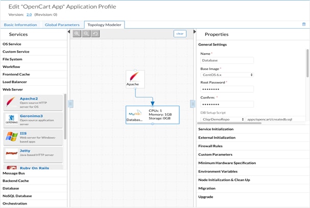
Deploying Production Instance of OpenCart Application on VersaStack On-premises
To deploy OpenCart application on VersaStack Private Cloud, complete the following steps:
1. Access the application from the CCM UI and click Applications.
2. Search for the required OpenCart application profile in the Applications page and click the profile to begin the deployment process.

3. When the main-panel refreshes, complete the General Information section. Name the Deployment <OpenCart-Prod> and select <Production> in the drop-down menu for TAGS.
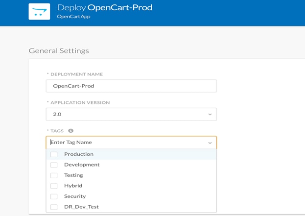
4. Select <Production> tag for both the Front-End (Apache) and Back-End (Database) Tiers and click NEXT.
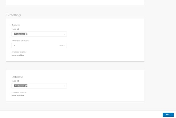
5. Select the Cloud where we want to deploy the application, in this case its <VersaStack_SVC_Private> cloud.
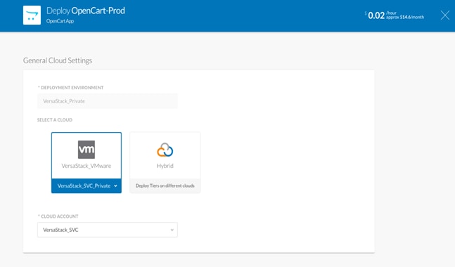
6. Select the instance type, the size of the VM that needs to be deployed for each tier with in OpenCart application.
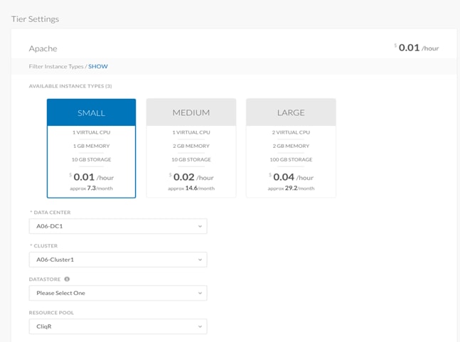

7. Click Deploy to start the application deployment process. The deployment process completes when the lights against each tier turns green.
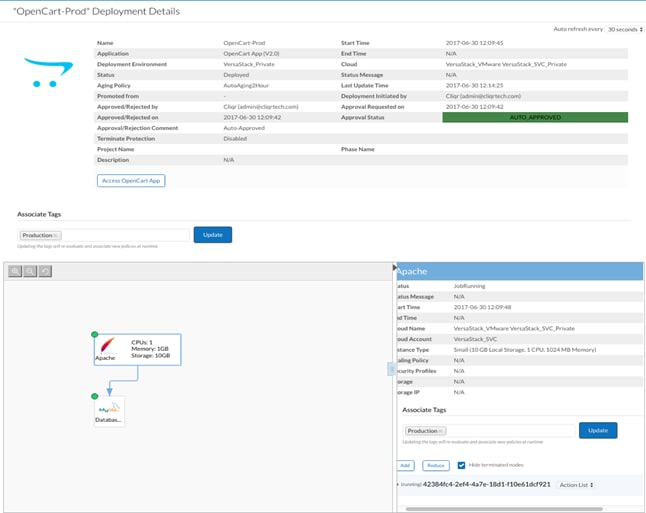
8. Click Access OpenCart App to access the application in a browser.
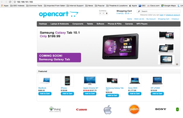
Deploying Dev-Test Instance of OpenCart Application at IBM Bluemix Cloud
To deploy OpenCart application on IBM Bluemix Public Cloud, complete the following steps:
1. Access the application from the CCM UI and click Applications.
2. Search for the required OpenCart application profile in the Applications page and click the profile to begin the deployment process.
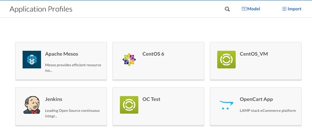
3. When the main-panel refreshes, complete the General Information section. Name the Deployment <OpenCart-Dev> and select P in the drop-down menu for TAGS.
4. Name the Deployment <OpenCart-Dev> and select <Development> in the drop-down menu for TAGS.
5. Select <Development> tag for both the Front-End (Apache) and Back-End (Database) Tiers and click NEXT.
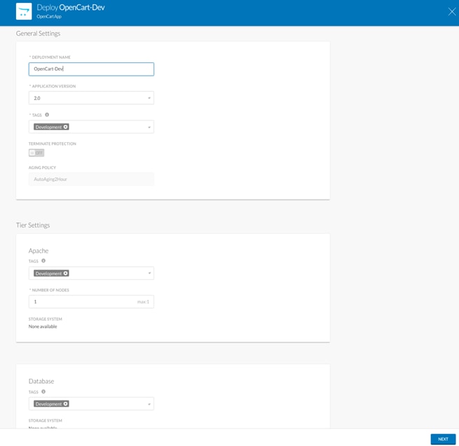
6. Select the Cloud where we want to deploy the application; in this case it is <Softlayer cloud>.
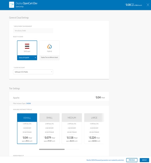
7. Click Deploy to start the application deployment process. The deployment process completes when the lights against each tier turns green.
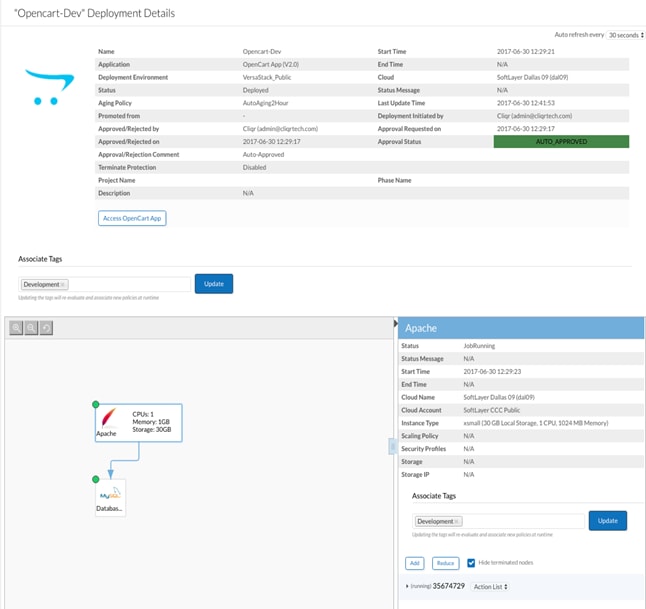
8. Click Access OpenCart App to access the application in a browser.
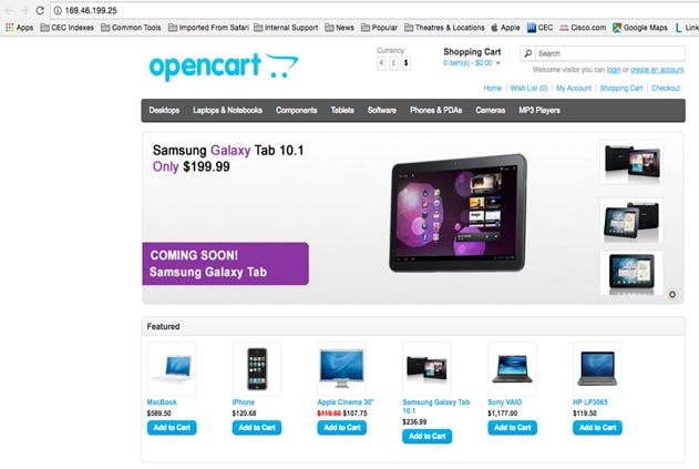
Production Data Availability for Dev-Test Instance
There are many ways to make production data available for Dev-Test instances when application instances are deployed in the IBM Bluemix cloud. When an application instance is deployed in the Public Cloud that the customers want to utilize for testing purposes, it is extremely beneficial to have the production data also available to the application which provides the test users identical environment to production.
Within this solution validation we have leveraged basic OS utility “rsync” to replicate production data from VersaStack Private Cloud OpenCart instance to the instance deployed at the IBM Bluemix cloud. Customers can leverage any utility such as backup and restore of databases for example to make the production data available in the Public Cloud.
There are different approaches available for data migration and replication for specific applications; customers should work with Cisco's Professional Services to identify the best approach for data availability in the Public Cloud.
To enable production data availability for OpenCart instances deployed in Softlayer Cloud, complete the following steps:
1. Create a user in OpenCart application running on VersaStack.
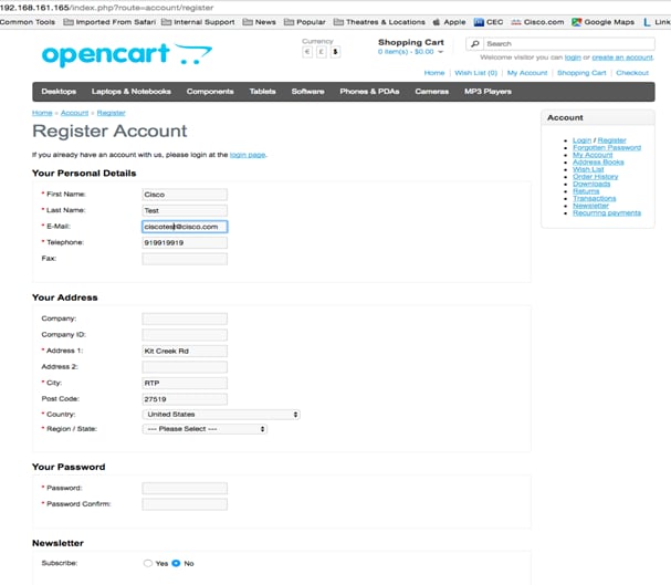
2. Add a few items to the cart; these items will be available in the Softlayer cloud after you replicate the database.
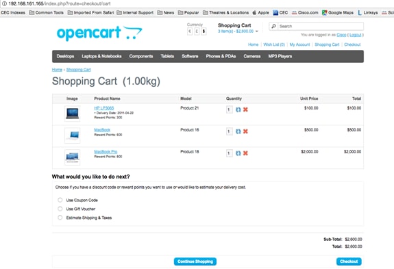
3. SSH to the OpenCart Dev-Test mysql server instance using Softlayer assigned IP address.
4. Stop the mysql server using the following command
[root@cqjw-c9e81faea mysql]# mysqld stop
5. SSH to the OpenCart Production mysql server instance using assigned IP address.
6. Execute the following rsync command to replicate the OpenCart directory to Dev-Test instance of mysql running in IBM Bluemix cloud.
[root@cqjw-685812f1b mysql]# rsync -avz /data/mysql/opencart/ root@169.46.199.3:/data/mysql/opencart
7. Type reboot in the Linux command prompt of the Dev-Test instance, reboot of the server is recommended to access new data.
8. When the server is back online, access the OpenCart application and login using the user you created in OpenCart running at VersaStack data center and verify that the items that you added are available in the cart.

![]() The steps detailed above are just one example of how you can make the production data available to Dev-Test OpenCart instance deployed in Softlayer public cloud. When following a specific procedure, make sure that the dependencies are taken care of and consult the application owner and Cisco for a successful implementation.
The steps detailed above are just one example of how you can make the production data available to Dev-Test OpenCart instance deployed in Softlayer public cloud. When following a specific procedure, make sure that the dependencies are taken care of and consult the application owner and Cisco for a successful implementation.
This section describes how to configure IP replication between the IBM cluster at VersaStack production data center and the IBM V7000 deployed at the VersaStack secondary data center designated for disaster recovery and Dev-Test purposes.
Our inter-site connectivity consists of two 1 gigabits per second (Gbps) links. For the IP replication traffic, the example uses port 2 on each SVC node and V7000.
Before configuring IP replication, make that the following prerequisites have been met:
· Confirm the presence and details of the inter-site IP links to be used for replication traffic between your partner systems.
· Determine the number of Ethernet ports and replication port groups to be used.
· Obtain IP addresses for the IP ports to be used, and ensure that the inter-site links support the routing of traffic between the addresses on each end, and that Transmission Control Protocol (TCP) ports 3260 and 3265 are open for traffic between the partner systems.
Configure the Ethernet Ports on the Partner Systems
This section describes the steps to configure the IP ports on the partner systems.
Configuring the Ethernet ports on SVC Cluster
To configure the IP ports on SVC Cluster, complete the following steps:
1. Access the Network pane in the web-based GUI using the Settings icon in the left navigation menu.
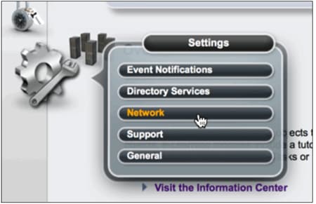
![]() The IP addresses (IPs) used in this scenario are just one example of what IPs can be used. Any range of IPs are allowable, private networks included, if they conform with your own IP network and the requirements.
The IP addresses (IPs) used in this scenario are just one example of what IPs can be used. Any range of IPs are allowable, private networks included, if they conform with your own IP network and the requirements.
![]() In the lab environment used for the examples in this section, Ethernet port 2 is configured on each of the SVC and V7000 nodes on the partner systems. Alternative Ethernet port configurations are supported.
In the lab environment used for the examples in this section, Ethernet port 2 is configured on each of the SVC and V7000 nodes on the partner systems. Alternative Ethernet port configurations are supported.
2. On the Network pane, click Ethernet Ports in the left Network menu.
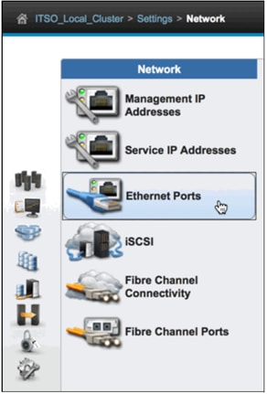
3. Right-click the row of the wanted port and select Modify to modify its IP settings. In this example, configure port 2 on node 1.
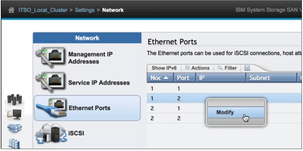
4. In the Modify Port dialog window, enter the appropriate values for IP address, Subnet mask, and Gateway. In this example, the following values were used for port 2 on node 1:
IP address 192.168.1.10
Subnet mask 255.255.255.0
Gateway 192.168.1.1
iSCSI hosts Disabled
Remote copy Group 1
5. Additionally, select or clear the iSCSI hosts box to enable or disable Internet Small Computer System Interface (iSCSI) host traffic on this port. In this example, clear the box to disable iSCSI traffic on this port.
6. To enable the port for IP replication, use the Remote copy radio buttons to select a port group. In this example, choose Group 1 for Ethernet port 2.

7. When you click OK, the Modify Ethernet Port IP address dialog window will display the task status for modifying the Ethernet port IP address settings. After the task completes, click Close to close the task status window.
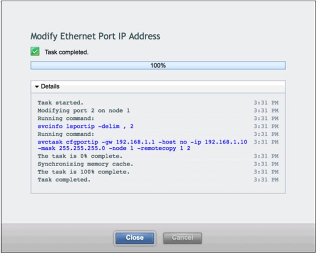
![]() Although sharing IP ports for both IP replication traffic and iSCSI host traffic is supported, for performance purposes, it is advised to isolate IP replication traffic.
Although sharing IP ports for both IP replication traffic and iSCSI host traffic is supported, for performance purposes, it is advised to isolate IP replication traffic.
8. The Ethernet Ports pane should now reflect the changes made. Ensure that your settings are correct.
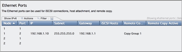
9. Repeat steps 3 on page 25 to 8 to configure the IP settings for port 2 on node 2. In this example, the following values were used for port 2 on node 2:
IP address 192.168.1.11
Subnet mask 255.255.255.0
Gateway 192.168.1.1
iSCSI hosts Disabled
Remote copy Group 2
10. The Ethernet Ports pane should now reflect the changes made to port 2 on node 2.
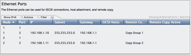
Configuring the Ethernet Ports on IBM Storwize V7000
To configure the IP ports on V7000, access the web-based GUI of IBM Storwize V7000, and repeat the procedure outlined in “Configuring the Ethernet ports on IBM SVC, using the appropriate values.
In this example, configure the Ethernet Ports using the following values:
Port 2 on Node 1
IP address <192.168.1.12>
Subnet mask <255.255.255.0>
Gateway <192.168.1.1>
iSCSI hosts Disabled
Remote copy Group 1
Port 2 on Node 2
IP address <192.168.1.13>
Subnet mask <255.255.255.0>
Gateway <192.168.1.1>
iSCSI hosts Disabled
Remote copy Group 2
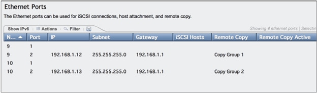
The Ethernet port settings are now complete and you can proceed to configure the IP partnership.
Create and Configure the IP Partnership on Each Partner System
This section details the steps to configure the IP partnership on the partner systems.
Configuring the IP partnership on IBM SVC Cluster
To configure the IP partnership on IBM SVC Cluster, complete the following steps:
1. Access the Partnerships pane in the web-based GUI using the Copy Services icon in the left navigation menu.
![]() To create a Partnership between SVC and Storwize family systems, those systems must be in the same layer. SVC systems are always in the replication layer. Storwize systems are in the storage layer by default, but can be configured in the replication layer. To create a partnership between an SVC and a Storwize system, you must make sure that the Storwize system layer is set to replication.
To create a Partnership between SVC and Storwize family systems, those systems must be in the same layer. SVC systems are always in the replication layer. Storwize systems are in the storage layer by default, but can be configured in the replication layer. To create a partnership between an SVC and a Storwize system, you must make sure that the Storwize system layer is set to replication.
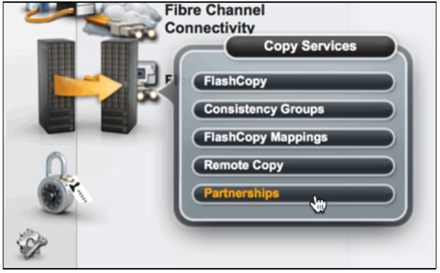
2. On the Partnerships pane, click Create Partnership.
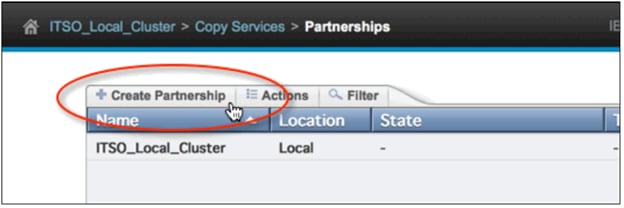
3. In the Create Partnership dialog window, select IP.
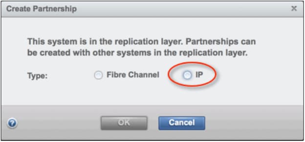
4. In the Create Partnership dialog window, enter values for Partner system IP address, Link bandwidth, Background copy rate, and optionally, Partner system’s CHAP secret.
In this example, the following values were used:
Partner system IP address <9.32.248.89>
Link bandwidth in megabits per second (Mbps) 2000 (our example environment contains two 1 Gbps intersite links)
Background copy rate (%) 50 (we chose to use up to 50% of the link bandwidth for the initial background synchronization)
Partner system’s CHAP secret None (the example environment does not use CHAP authentication)
5. For the partner system IP address, enter the management IP address (“cluster IP”) for the partner system. Do not enter the IP addresses that you configured for IP replication on the Ethernet ports of the partner system.

6. When you click OK, the Create IP Partnership dialog window will display the task status for creating the IP partnership. When the task completes, click Close to close the task status window.
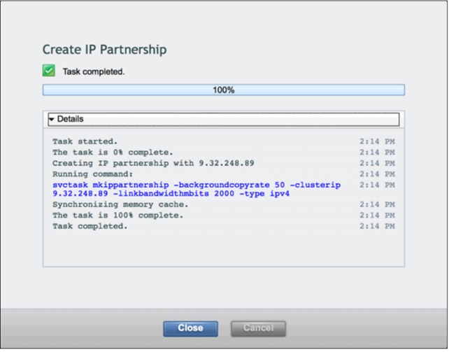
7. Confirm that the Partnerships pane displays the new partnership that you just created.
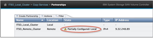
Configure the IP Partnership on IBM V7000 Remote System
To configure the IP partnership on V7000, access the web-based GUI of V7000 and repeat the procedure outlined in “Configuring the IP partnership on IBM SVC Cluster” above, using the appropriate values. In this example, configure the IP partnership on V7000 using the following values:
Partner system IP address <9.32.248.174>
Link bandwidth (Mbps) 2000 (the example environment contains two 1 Gbps intersite links)
Background copy rate (%) 50 (we chose to use up to 50% of the link bandwidth for the initial background synchronization)
Partner system’s CHAP secret None (our example environment does not use CHAP authentication)
1. After initially configuring the IP partnership on V7000, the Partnerships pane shows the state of this partnership as Not Present.
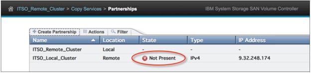
![]() Make note of the State of the partnership. When the partnership is successfully created on the first system, the State value on that system will display Partially Configured: Local. When the partnership is successfully created on the second system, the State on that system might initially display Not Present. After a brief period of time, the State value will display Fully Configured on each system if the IP partnership was successfully created on each partner system.
Make note of the State of the partnership. When the partnership is successfully created on the first system, the State value on that system will display Partially Configured: Local. When the partnership is successfully created on the second system, the State on that system might initially display Not Present. After a brief period of time, the State value will display Fully Configured on each system if the IP partnership was successfully created on each partner system.
2. After a few moments, the State of the IP partnership should display Fully Configured on both systems.

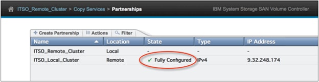
3. The IP partnership is now fully configured, and you can proceed to configure the remote-copy relationships.
This section describes the installation and configuration of IBM Spectrum Copy Data Management Solution.
![]() Make sure that you have the required system configuration and browser to deploy and run IBM Spectrum Copy Data Management.
Make sure that you have the required system configuration and browser to deploy and run IBM Spectrum Copy Data Management.
IBM Spectrum CDM Virtual Machine Installation
IBM Spectrum Copy Data Management is installed in the VersaStack VMware environment as a virtual appliance. Before deploying to the host, make sure you have the following:
· The correct OVF template, which has an OVA extension, and is approximately 1.4 GB l
· vSphere 5.1, 5.5, 6.0, or 6.5 l
· Network information and VMware host information l Either an available static IP address to use or access to DHCP
For the initial deployment, configure your virtual appliance to meet the following recommended minimum requirements:
· 64-bit dual core machine
· 32 GB memory
The appliance has the following three virtual disks that total 400 GB storage:
· 50 GB for operating system and application, which includes 16 GB for the swap partition, 256 MB for the boot partition, and the remainder for the root partition
· 100 GB for configuration data related to jobs, events, and logs
· 250 GB for Inventory data
It is recommended that the IBM Spectrum Copy Data Management appliance, storage arrays, hypervisors and application servers in your environment use NTP
· Browser Support
![]() Run IBM Spectrum Copy Data Management from a computer that has access to the installed virtual appliance.
Run IBM Spectrum Copy Data Management from a computer that has access to the installed virtual appliance.
IBM Spectrum Copy Data Management was tested and certified against the following web browsers. Note that newer versions may be supported.
· Internet Explorer 11
· Microsoft Edge 20.10240
· Firefox 49.0
· Chrome 53.0.27
Pop-up windows must be enabled in your browser to access the Help system and some IBM Spectrum Copy Data Management operations.
IBM Storage Requirements
This solution consists of IBM SAN Volume Controller at the production VersaStack site and IBM Storwize V7000 at the VersaStack secondary data center. In general, following storage requirements should be met if customers are using different storage arrays:
· IBM storage systems running IBM SpectrumTM Virtualize Software version 7.3 and later, including IBM SAN Volume Controller, IBM Storwize, and IBM FlashSystem V9000 systems
· IBM storage systems running IBM Spectrum Accelerate version 11.5.3 and later, including FlashSystem A9000/A9000R and IBM XIV storage systems
Installation
To install IBM Spectrum Copy Data Management, you need to deploy an OVF template. This creates a virtual appliance containing the application on a VMware host such as an ESX or ESXi server.
To install IBM Spectrum Copy Data Management as a virtual appliance.
To install IBM Spectrum Copy Data Management, deploy an OVF template. This creates a virtual appliance containing the application on a VMware host such as an ESX or ESXi server.
To install IBM Spectrum Copy Data Management as a virtual appliance, complete the following steps:
1. Use the vSphere Client to deploy IBM Spectrum Copy Data Management. From the File menu, choose Deploy OVF Template.
2. Specify the location of the IBM Spectrum Copy Data Management OVA template file and select it. Click Next.
3. Review the template details and accept the End User License Agreement. Click Next.
4. Provide a meaningful name for the template, or use Default name ‘IBM Spectrum Copy Data Management’, which becomes the name of your virtual machine. Identify an appropriate location to deploy the virtual machine. Click Next.
5. Identify the production data center, server, and resource pool for deployment. When prompted to select storage, select from datastores already configured on the destination host. The virtual machine configuration file and virtual disk files are stored on the datastore. Select a datastore large enough to accommodate the virtual machine and all of its virtual disk files. Click Next.
6. Select a disk format to store the virtual disks. It is recommended that you select thick provisioning, which is preselected for optimized performance. Thin provisioning requires less disk space, but may impact performance. Click Next.
7. Select networks for the deployed template to use. Several available networks on the ESX server maybe available by clicking Destination Networks. Select a destination network that allows you to define the appropriate IP address allocation for the virtual machine deployment. Click Next.
8. Enter network properties for the virtual machine's default gateway, DNS, IP address and netmask. Leave fields blank to retrieve settings from a DHCP server. The virtual machine needs access to a DHCP server available on the configured destination network. Click Next.
9. Review your template selections. Click Finish to exit the wizard and to start deployment of the OVF template. Deployment might take significant time.
10. After OVF template deployment completes, power on your newly created virtual machine. This can be done from vSphere Client.
![]() The virtual machine must remain powered on for the IBM Spectrum Copy Data Management application to be accessible.
The virtual machine must remain powered on for the IBM Spectrum Copy Data Management application to be accessible.
11. Make a note of the IP address of the newly created virtual machine. This is needed to logon to the application. Find the IP address in vSphere Client by clicking your newly created virtual machine and looking in the Summary tab.
![]() You must allow few minutes for IBM Spectrum Copy Data Management to initialize completely.
You must allow few minutes for IBM Spectrum Copy Data Management to initialize completely.
Launch IBM Spectrum Copy Data Management to begin using the application and its features.
To start IBM Spectrum Copy Data Management, complete the following steps:
1. From a supported browser, enter the following URL: https://<HOSTNAME>:8443/portal/ where <HOSTNAME> is the IP address of the virtual machine where the application is deployed. This connects you to IBM Spectrum Copy Data Management.
2. In the logon dialog, enter your username and password. If this is your first-time logging onto IBM Spectrum Copy Data Management as a Super User, the default user name is admin and the default password is password. You will be prompted to reset the default Super User password.
3. Click Sign In. The application launches. The Home ![]() tab displays the dashboard.
tab displays the dashboard.
IBM Spectrum CDM Configuration
This section details how to configure IBM Spectrum CDM for VersaStack.
Register a Provider
The first step in configuring IBM Spectrum CDM for VersaStack is registering Providers.
Providers are physical servers that host objects and attributes. When a provider is registered in IBM Spectrum Copy Data Management, cataloging, searching, and reporting can be performed.
Supported provider types are:
Application servers. Supported application database types include InterSystems Caché, Oracle, SAP HANA, and SQL. Use the File System application type to register file systems for physical servers running Windows, Linux, and AIX. See associated application requirements for supported storage types.
IBM storage systems. Supported types include IBM Spectrum Accelerate, IBM Spectrum Protect Snapshot, and IBM Spectrum Virtualize.
![]() For VMware servers, supported types includes vCenter and ESX/ESXi hosts.
For VMware servers, supported types includes vCenter and ESX/ESXi hosts.
To register an Application Server hosted on VersaStack, complete the following steps:
1. Click the Configure ![]() tab. On the Views pane, select Sites & Providers
tab. On the Views pane, select Sites & Providers ![]() , then select the Providers tab.
, then select the Providers tab.
2. In the Provider Browser pane, select Application Server.
3. Right-click Application Server. Then click Register ![]() . The Register Application Server dialog opens.
. The Register Application Server dialog opens.
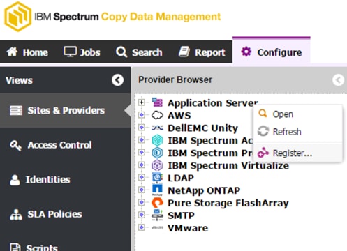
4. Select the Application Type. Oracle, SQL, Cache, SAP HANA, etc.
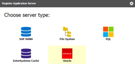
5. Populate the fields in the dialog:
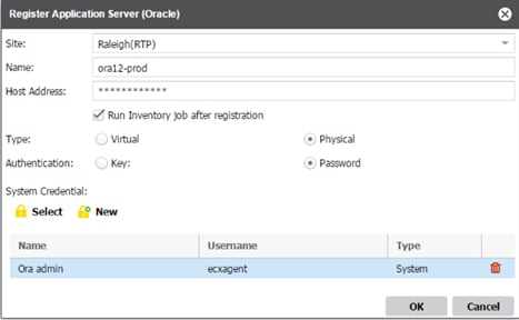
· Site
A user- Select the Production Site. By Default, Spectrum CDM chooses a Site name called Default. New sites can be created in the Sites & Providers ![]() view on the Configure tab.
view on the Configure tab.
· Name - This field can be the same as the host name or it can be a meaningful name that is used within your organization to refer to the provider. Provider names must be unique.
· Host Address - A resolvable IP address or a resolvable path and machine name.
![]() When registering cluster, register each node using its physical IP or name. Do not register a virtual name or SCAN (Single Client Access Name).
When registering cluster, register each node using its physical IP or name. Do not register a virtual name or SCAN (Single Client Access Name).
· System Credential: Select existing as shown in the screenshot or click New to create your application credentials.
· Type - Select a Virtual or Physical server type. Select Virtual if the application server is a VMware virtual machine.
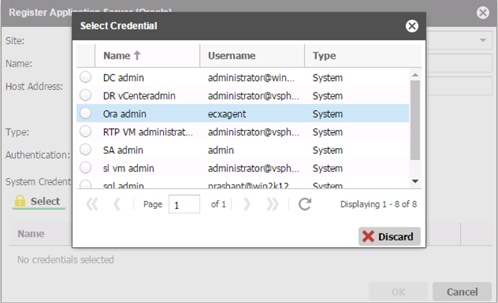
![]() AIX virtual servers should be registered as Physical.
AIX virtual servers should be registered as Physical.
6. If selecting Virtual, enter the vCenter location of the application server in the vCenter field.
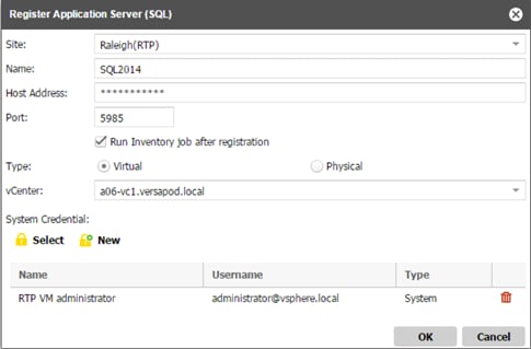
7. Click OK. IBM Spectrum Copy Data Management first confirms a network connection and then adds the provider to the database.
To troubleshoot an application server after registration, use the Test & Configure option. This option verifies communication with the server, tests DNS settings between the IBM Spectrum Copy Data Management appliance and the server, and installs an IBM Spectrum Copy Data Management agent on the server.
8. From the Provider Browser pane, right-click the application server, then click Test & Configure ![]() .
.
Register VersaStack Storage
To register the VersaStack storage IBM SVC in production and IBM Storwize V7000, complete the following steps:
1. Click the Configure ![]() tab. On the Views pane, select Sites & Providers
tab. On the Views pane, select Sites & Providers ![]() , then select the Providers tab.
, then select the Providers tab.
2. In the Provider Browser pane, select IBM Spectrum Virtualize ![]() .
.
3. Right-click IBM Spectrum Virtualize ![]() . Then click Register
. Then click Register ![]() . The Register dialog opens.
. The Register dialog opens.
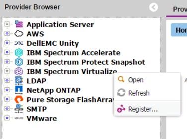
4. Populate the fields in the dialog:
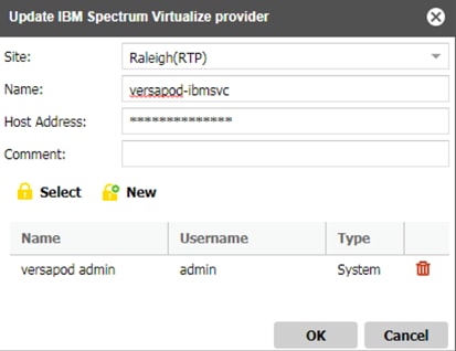
· Site - Choose the same Production site that was used to register the Application server.
· Name - Enter a name for the IBM provider. This can be the same as the host name or it can be a meaningful name that is used within your organization to refer to the provider. Provider names must be unique.
· Host Address – Enter a resolvable IP address or a resolvable path and machine name.
· Run Inventory job after registration - If selected, IBM Spectrum Copy Data Management creates a high-level Inventory job and automatically catalogs the objects on the provider.
· Credentials - Select or create your IBM Spectrum Virtualize credentials.
5. Click OK. IBM Spectrum Copy Data Management first confirms a network connection and then adds the provider to the database.
6. If a message appears indicating that the connection is unsuccessful, review your entries. If your entries are correct and the connection is unsuccessful, contact a system administrator to review the connections.
7. Repeat the same steps to register a second VersaStack storage IBM Storwize V7000, that will be used for replication. Create a new site name to register the non-production test systems.
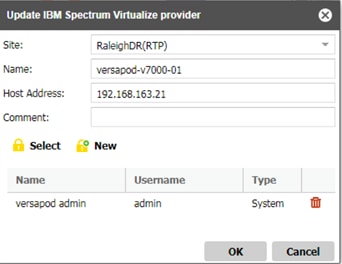
8. When the Providers are Registered they can be viewed in the Provider Browser.
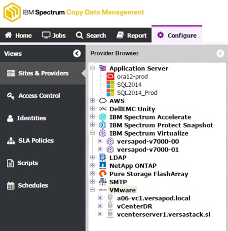
Configure SLA Policies
SLA Policies allow storage and virtualization administrators to create customized templates for the key processes involved in the creation and use of Backup jobs. Copy types, destinations, and parameters are configured in SLA Policies, which can be used and re-used in Backup jobs.
Generally, a storage administrator creates SLA Policies after registering storage providers in IBM Spectrum Copy Data Management and creating accounts that will create, edit, and run Backup and Restore jobs through role-based access control. When configuring a Backup job definition, available SLA Policies display in the job creation wizard, tailored to the type of Backup job being created.
To create an SLA Policy, complete the following steps:
1. Click the Configure tab. On the Views pane, select SLA Policies ![]() . The All SLA Policies pane opens.
. The All SLA Policies pane opens.
2. In the All SLA Policies pane, click New ![]() .The New SLA Policies pane opens.
.The New SLA Policies pane opens.
3. Select a type of policy to create based on your storage provider. Select IBM Spectrum Virtualize as shown in Figure to create an IBM Backup job containing FlashCopies, Global Mirrors with Change Volumes, and VM Copies.
4. Enter a name and a meaningful description of the SLA Policy.
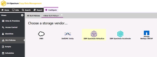
To add a FlashCopy sub-policy to an IBM Spectrum Virtualize SLA Policy, complete the following steps:
1. Enter a name <VersaStack_FlashCopy> and a meaningful description of the SLA Policy.
2. Select the source icon and define the recovery point objective to determine the minimum frequency and interval with which backups must be made. In the Frequency field select Hourly, Daily, Weekly, or Monthly, then set the interval in the Interval field.
3. Click Add FlashCopy ![]() .In the Options pane, set the FlashCopy sub-policy options.
.In the Options pane, set the FlashCopy sub-policy options.
· Keep Snapshots - After a certain number of snapshot instances are created for a resource, older instances are purged from the storage controller. Enter the age of the snapshot instances to purge in the Days field, or the number of instances to keep in the Snapshots field.
· Name Enter an optional name to replace the default FlashCopy sub-policy name displayed in IBM Spectrum Copy Data Management. The default initial name is FlashCopy0. FlashCopy
· Volume Prefix - Enter an optional label to identify the FlashCopy. This label is added as a prefix to the FlashCopy name created by the job.
![]() FlashCopy labels must contain only alphanumeric characters and underscores.
FlashCopy labels must contain only alphanumeric characters and underscores.
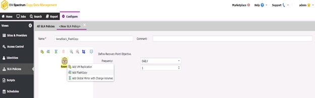
4. To enable an Incremental FlashCopy, select Enable Incremental FlashCopy in the Incremental FlashCopy Storage Pool pane.
5. Select an IBM host destination from the list of available resources as the FlashCopy destination, along with an associated storage pool. If no storage pool is selected, the storage pool with the largest amount of space available is chosen by default.
6. To select the original target destination, select Use Original. If the Enable Incremental FlashCopy option is selected, note that the base FlashCopy will be sent to the destination selected in the Incremental FlashCopy Storage Pool pane. Subsequent incremental FlashCopies will be sent to the destination selected in the Target FlashCopy Storage Pool pane.
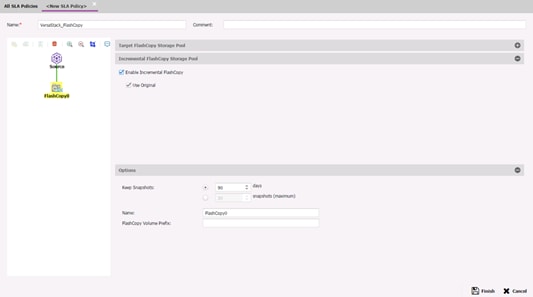
![]() The Target FlashCopy Storage Pool must reside on the same storage system as the Incremental FlashCopy Storage Pool.
The Target FlashCopy Storage Pool must reside on the same storage system as the Incremental FlashCopy Storage Pool.
To add a Global Mirror with Change Volumes sub-policy to an IBM Spectrum Virtualize SLA Policy, complete the following steps:
1. Enter a name <VersaStack_GlobalMirror> and a meaningful description of the SLA Policy.
2. Select the source icon and define the recovery point objective to determine the minimum frequency and interval with which backups must be made. In the Frequency field select Hourly, Daily, Weekly, or Monthly, then set the interval in the Interval field.
3. Click Add Global Mirror with Change Volumes ![]() .
.
4. In the Global Mirror with Change Volumes Destination pane select an IBM host destination from the list of available resources as the Global Mirror destination, along with an associated storage pool. If no storage pool is selected, the storage pool with the largest amount of space available is chosen by default. To select the original target destination, select Use Original.
5. In the Options pane set the Global Mirror with Change Volumes sub-policy options.
· Keep Snapshots - Enter the age of the snapshot instances to purge in the Days field, or the number of instances to keep in the Snapshots field.
· Cycle Period (seconds) - Specify the time in which the change volumes will be refreshed with a consistent copy of the data. If a copy does not complete in the cycle period, the next cycle period will not start until the copy is complete. The range of possible values is 60 through 86400. The default is 300.
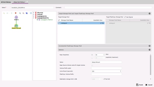
This section describes the process of protecting application deployed on VersaStack primary data center using IBM Spectrum Copy Data Management.
Create a Backup Job Definition - Oracle
IBM Spectrum Copy Data Management provides application database copy management through application- consistent backup creation, cloning, and recovery. IBM Spectrum Copy Data Management copy management leverages the snapshot and replication features of the underlying IBM storage platform to create, replicate, clone, and restore backups of Oracle databases. Archive log destinations as well as universal destination mount points are supported. Archived logs are automatically deleted upon reaching defined retention.
IBM Spectrum Copy Data Management auto-discovers databases and enables backups only of eligible databases. To be eligible for backup, application databases must reside on supported storage platforms.
The following options are available for Oracle Backup jobs:
· RMAN Integration - Oracle Recovery Manager (RMAN), a command-line and Enterprise Manager-based tool, is the method preferred by Oracle database administrators for backup and recovery of Oracle databases, including maintaining an RMAN repository. IBM Spectrum Copy Data Management automates cataloging of Oracle database backups in the RMAN recovery catalog, enabling database administrators to leverage RMAN for verification and advanced recovery.
· Data Masking - Data masking is used to hide confidential data by replacing it with fictitious data. This feature is used when making data copies for DevTest or other use cases.
· Log Backup - The log backup feature enables continuous backups of Archive logs to a specified destination. Archive log retention is managed by settings in RMAN. IBM Spectrum Copy Data Management leverages archived logs to enable point-in-time recoveries of databases to facilitate RPOs.
To create an Oracle Backup job definition, complete the following steps:
1. Click the Jobs ![]() tab. Expand the Database folder, then select Oracle.
tab. Expand the Database folder, then select Oracle.
2. Right-click, then select Backup. The job editor opens.
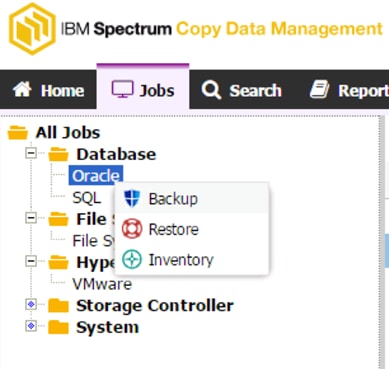
3. Enter a name, for example, <dbname>_Backup, for your job definition and a meaningful description.
4. From the list of available sites select the Production site. Expand Oracle home directories to view associated application databases.
![]() You cannot select a database if it is not eligible for protection. Hover your cursor over the database name to view the reasons the database is ineligible, such as the database files, control files, or redo log files are stored on unsupported storage.
You cannot select a database if it is not eligible for protection. Hover your cursor over the database name to view the reasons the database is ineligible, such as the database files, control files, or redo log files are stored on unsupported storage.
5. Select SLA policies <VersaStack_FlashCopy> and <VersaStack_GlobalMirror>

6. Click the job definition's associated Schedule Time field and select Enable Schedule to set a time to run the SLA Policy. If a schedule is not enabled, run the job on demand through the Jobs ![]() tab. Repeat as necessary to add additional SLA Policies to the job definition. Select the Same as workflow option to trigger both SLA Policies to run concurrently.
tab. Repeat as necessary to add additional SLA Policies to the job definition. Select the Same as workflow option to trigger both SLA Policies to run concurrently.
![]() Only SLA Policies with the same RPO frequencies can be linked through the Same as workflow option. Define an RPO frequency when creating an SLA Policy.
Only SLA Policies with the same RPO frequencies can be linked through the Same as workflow option. Define an RPO frequency when creating an SLA Policy.
7. To create the job definition using default options, click Create Job. The job runs as defined by your triggers, or can be run manually from the Jobs ![]() tab.
tab.
8. To edit options before creating the job definition, click Advanced. Set the job definition options:
· Maximum Concurrent Tasks - Set the maximum amount of concurrent transfers between the source and the destination.
· Record copies in RMAN local repository - Enable to create a local backup of the Recovery Manager (RMAN) catalog during the running of Oracle Backup job. RMAN catalogs can be used for backup, recovery, and maintenance of Oracle databases outside of IBM Spectrum Copy Data Management.
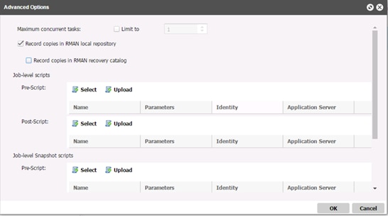
![]() Oracle databases must be registered in the recovery catalog before running an Oracle Backup job utilizing the Record copies in RMAN recovery catalog feature.
Oracle databases must be registered in the recovery catalog before running an Oracle Backup job utilizing the Record copies in RMAN recovery catalog feature.
9. Optionally, expand the Notification section to select the job notification options. From the list of available SMTP resources, select the SMTP Server to use for job status email notifications.
10. To edit Log Backup options before creating the job definition, click Log Backup. If Create additional archive log destination is selected as shown in the screenshot below, IBM Spectrum Copy Data Management backs up database logs then protects the underlying disks. The default option is Use existing archive log destination(s).
![]() IBM Spectrum Copy Data Management automatically discovers the location where Oracle writes archived logs. If this location resides on storage from a supported vendor, IBM Spectrum Copy Data Management can protect it. If the existing location is not on supported storage, or if you wish to create an additional backup of database logs, enable the Create additional archive log destination option, then specify a path that resides on supported storage. When enabled, IBM Spectrum Copy Data Management configures the database to start writing archived logs to this new location in addition to any existing locations where the database is already writing logs.
IBM Spectrum Copy Data Management automatically discovers the location where Oracle writes archived logs. If this location resides on storage from a supported vendor, IBM Spectrum Copy Data Management can protect it. If the existing location is not on supported storage, or if you wish to create an additional backup of database logs, enable the Create additional archive log destination option, then specify a path that resides on supported storage. When enabled, IBM Spectrum Copy Data Management configures the database to start writing archived logs to this new location in addition to any existing locations where the database is already writing logs.
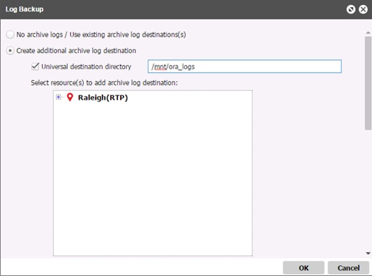
11. When you are satisfied that the job-specific information is correct, click Create Job. The job runs as defined by your schedule, or can be run manually from the Jobs ![]() tab.
tab.
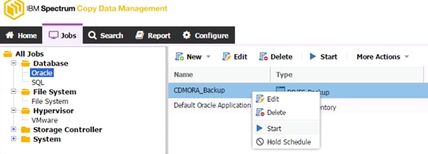
12. Job progress can be monitored as shown in the tab below:
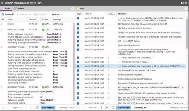
Create a Backup Job Definition - SQL
IBM Spectrum Copy Data Management provides Microsoft SQL database copy management through application- consistent backup creation, cloning, and recovery. IBM Spectrum Copy Data Management copy management leverages the snapshot and replication features of the underlying storage platform to create, replicate, clone, and restore copies of Microsoft SQL Servers. Archive log destinations as well as universal destination mount points are supported. Archived logs are automatically deleted upon reaching defined retention.
IBM Spectrum Copy Data Management auto-discovers databases and enables backups only of eligible databases. To be eligible for backup, application databases must reside on supported storage platforms.
The following option is available for SQL Backup jobs:
· Log Backup - The log backup feature enables continuous backup of Archive logs to a specified destination. IBM Spectrum Copy Data Management leverages archived logs to enable point-in-time recoveries of databases to facilitate RPOs.
To create a SQL Backup job definition, complete the following steps:
1. Click the Jobs ![]() tab. Expand the Database folder, then select SQL.
tab. Expand the Database folder, then select SQL.
2. Right-click, then select Backup. The job editor opens.

3. Select a Standalone or Failover Cluster or AlwaysOn Availability Group workflow template.
4. Enter a name for your job definition, for example, <dbname>_Backup and a meaningful description.
5. From the list of available sites select the Production site to backup. Expand servers to view associated application databases.
![]() You cannot select a database if it is not eligible for protection. Hover your cursor over the database name to view the reasons the database is ineligible, such as the database files, control files, or redo log files are stored on unsupported storage.
You cannot select a database if it is not eligible for protection. Hover your cursor over the database name to view the reasons the database is ineligible, such as the database files, control files, or redo log files are stored on unsupported storage.
6. Select the SLA Policies <VersaStack_FlashCopy> and <VesaStack_GlobalMirror>
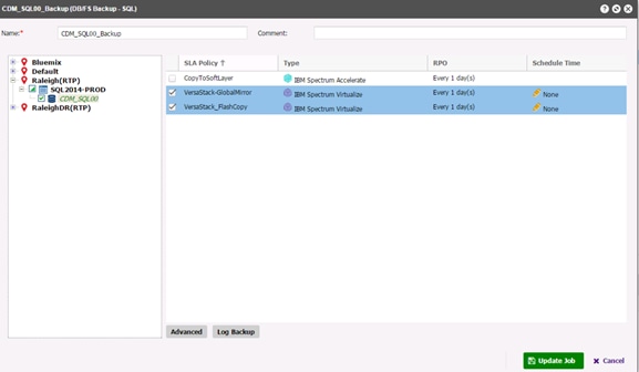
7. Click the job definition's associated Schedule Time field and select Enable Schedule to set a time to run the SLA Policy. If a schedule is not enabled, run the job on demand through the Jobs ![]() tab. Select the Same as workflow option to trigger both SLA Policies to run concurrently.
tab. Select the Same as workflow option to trigger both SLA Policies to run concurrently.
![]() Only SLA Policies with the same RPO frequencies can be linked through the Same as workflow option. Define an RPO frequency when creating an SLA Policy.
Only SLA Policies with the same RPO frequencies can be linked through the Same as workflow option. Define an RPO frequency when creating an SLA Policy.
8. To create the job definition using default options, click Create Job. The job runs as defined by your triggers, or can be run manually from the Jobs ![]() tab.
tab.
9. To edit options before creating the job definition, click Advanced. Set the job definition options:
· Maximum Concurrent Tasks Set the maximum amount of concurrent transfers between the source and the destination. Maximum Concurrent Snapshots on ESX Set the maximum number of concurrent snapshots on the vCenter.
· Job-Level Scripts Job-level pre-scripts and post-scripts are scripts that can be run before or after a job runs at the job-level. A script can consist of one or many commands, such as a shell script for Linux-based virtual machines or Batch and PowerShell scripts for Windows-based virtual machines.
· In the Pre-Script and/or Post-Script section, click Select to select a previously uploaded script, or click Upload to upload a new script. Note that scripts can also be uploaded and edited through the Scripts
· Select Continue operation on script failure to continue running the job if a command in any of the scripts associated with the job fails.
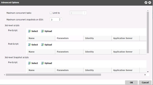
10. Optionally, expand the Notification section to select the job notification options. From the list of available SMTP resources, select the SMTP Server to use for job status email notifications
11. To edit Log Backup options before creating the job definition, click Log Backup. If Backup Logs is selected, IBM Spectrum Copy Data Management backs up database logs then protects the underlying disks. Select resources in the Select resource(s) to add archive log destination field. Database logs are backed up to the directory entered in the Use Universal Destination Mount Point field, or in the Mount Point field after resources are selected. The destination must already exist and must reside on storage from a supported vendor.
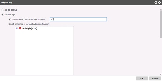
12. IBM Spectrum Copy Data Management automatically truncates post log backups of databases that it backs up. If database logs are not backed up with IBM Spectrum Copy Data Management, logs are not truncated by IBM Spectrum Copy Data Management and must be managed separately.
13. To disable a log backup schedule on the SQL server, edit the associated SQL Backup job definition and deselect the checkbox next to the database on which you wish to disable the log backup schedule in the Select resource(s) for log backup destination field, then save and re-run the job.
14. When you are satisfied that the job-specific information is correct, click Create Job. The job runs as defined by your schedule, or can be run manually from the Jobs ![]() tab.
tab.
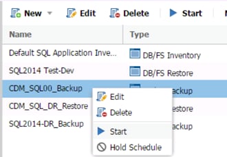
15. Job progress can be monitored in the tab as show below:
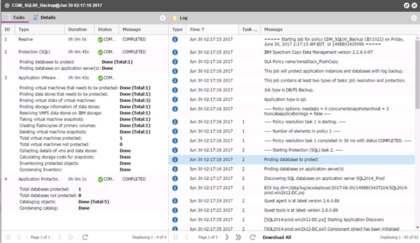
Create a Restore Job Definition - Oracle
IBM Spectrum Copy Data Management Leverages Copy Data Management technology for recovering application databases through Database Restore jobs. Your Oracle clones can be utilized and consumed instantly through IBM Spectrum Copy Data Management Instant Disk Restore jobs. IBM Spectrum Copy Data Management catalogs and tracks all cloned instances. Instant Disk Restore leverages ISCSI or fibre channel protocols to provide immediate mount of LUNs without transferring data. Snapshotted databases are cataloged and instantly recoverable with no physical transfer of data. Point-in-time recovery is supported with log forwarding.
The following Oracle Database workflows are supported; DevOps, which provides Instant Disk Restore or Instant Recovery to a new location using a masked image, created through a Restore job with data masking enabled, Instant Database Recovery, which provides Instant Disk Restore or Instant Recovery using a non- masked image and point-in-time transaction logs, and Instant Disk Restore, which mounts a database for RMAN restores with application and operating system support.
To create an Oracle Restore job definition, complete the following steps:
1. Click the Jobs ![]() tab. Expand the Database folder, then select Oracle.
tab. Expand the Database folder, then select Oracle.
2. Right-click, then select Restore. The job editor opens.

3. Enter a name for your job definition and a meaningful description.
4. Select the template Instant Database Restore. Available options include DevOps ![]() ,Instant Database Restore
,Instant Database Restore ![]() , and Instant
Disk Restore
, and Instant
Disk Restore ![]() .
.
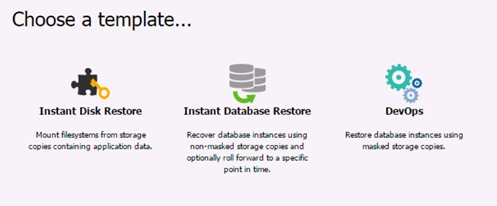
5. Click Source ![]() . From the drop-down menu select Application Browse to select the Production site and the oracle server to view available database recovery points as shown in Figure. Select resources, and change the order in which the resources are recovered by dragging and dropping the resources in the grid.
Alternatively, select Application Search from the drop-down menu to search for application servers with available recovery points. Add copies to the job definition by clicking Add. Change the order in which the resources are recovered by dragging and dropping the resources in the grid.
. From the drop-down menu select Application Browse to select the Production site and the oracle server to view available database recovery points as shown in Figure. Select resources, and change the order in which the resources are recovered by dragging and dropping the resources in the grid.
Alternatively, select Application Search from the drop-down menu to search for application servers with available recovery points. Add copies to the job definition by clicking Add. Change the order in which the resources are recovered by dragging and dropping the resources in the grid.
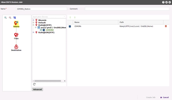
6. Click Copy ![]() . Sites containing copies of the selected data display. Select the Production site to restore from Production VersaStack or Secondary to restore from replicated site. By default, the latest copy of your data is used as shown in Figure. To choose a specific version, Click the Version field to view specific copies and their associated job and completion time. If recovery from one snapshot fails, another copy from the same site is used. An additional recovery option is available through the Select Version feature. Enable Allow Point-in-Time selection when job runs to leverage archived logs and enable a point-in-time recovery of the databases.
If creating an Instant Disk Restore
. Sites containing copies of the selected data display. Select the Production site to restore from Production VersaStack or Secondary to restore from replicated site. By default, the latest copy of your data is used as shown in Figure. To choose a specific version, Click the Version field to view specific copies and their associated job and completion time. If recovery from one snapshot fails, another copy from the same site is used. An additional recovery option is available through the Select Version feature. Enable Allow Point-in-Time selection when job runs to leverage archived logs and enable a point-in-time recovery of the databases.
If creating an Instant Disk Restore ![]() job definition, the RMAN tag displays next to the time in the Version field. An Oracle administrator can correlate the RMAN backups to the IBM Spectrum Copy Data Management versions during job creation.
job definition, the RMAN tag displays next to the time in the Version field. An Oracle administrator can correlate the RMAN backups to the IBM Spectrum Copy Data Management versions during job creation.
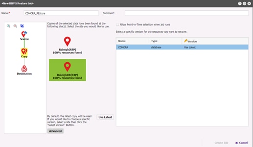
7. Click Destination ![]() . Select a Secondary site and an associated Oracle home. Click the Destination field to enter an optional alternate name for the database.
. Select a Secondary site and an associated Oracle home. Click the Destination field to enter an optional alternate name for the database.
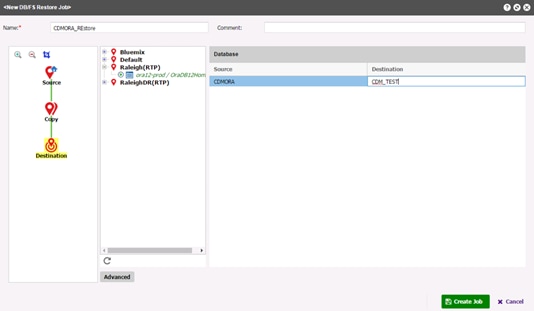
8. To create the job definition using default options, click Create Job. The job can be run manually from the Jobs ![]() tab.
tab.
9. To edit options before creating the job definition, click Advanced. Set the job definition options.
Application Options
· Record mounted copies in RMAN local repository - This option is available for Instant Disk Restore workflows. Select this option to catalog mounted copies into RMAN at the end of the Instant Disk Restore job.

· Rename Mount Points and Database Initialization Parameters – This option allows you to set different Mount Points and Database initialization parameters.
· ASM Disk Names - This option allows you to specify the disk naming pattern for restored ASM disks, if available. If Use default pattern is selected, IBM Spectrum Copy Data Management uses the default naming pattern, which is /dev/ecx-asmdisk/* in Linux environments or /dev/ecx_asm* in AIX environments. Select Specify a custom pattern to set ASM disks to follow any naming conventions that may be in use for existing disks. The custom pattern must begin with "/dev" and must end with an asterisk (*). During restore, IBM Spectrum Copy Data Management creates a device alias, or symlink, matching the specified pattern and replaces the asterisk with a unique disk name.
![]() This option has no effect if the database being restored does not use any ASM disks.
This option has no effect if the database being restored does not use any ASM disks.
Policy Options
· Continue with next source on failure
· Replace existing database - This option is available for Instant Database Recovery workflows. Select this option to replace an existing database with the same name during recovery.
· Job-Level Scripts - Job-level pre-scripts and post-scripts are scripts that can be run before or after a job runs at the job-level. A script can consist of one or many commands, such as a shell script for Linux-based virtual machines or Batch and PowerShell scripts for Windows-based virtual machines. Select Continue operation on script failure to continue running the job if a command in any of the scripts associated with the job fails.
Storage Options
· Make Permanent - Set the default permanent restoration action of the job. All database recovery operations can leverage Instant or Test modes and then either be deleted or promoted to permanent mode. This behavior is controlled through the Make Permanent option.
· Protocol Priority - If more than one storage network protocol is available, select the protocol to take priority in the job. Available protocols include iSCSI and Fibre Channel.
10. Optionally, expand the Notification section to select the job notification options. From the list of available SMTP resources, select the SMTP Server to use for job status email notifications. If an SMTP server is not selected, an email is not sent.
11. Enter the email addresses of the status email notifications recipients. Click Add ![]() to add it to the list.
to add it to the list.
12. Optionally, expand the Schedule section to select the job scheduling options. Select Start job now to create a job that starts the job immediately. Select Schedule job to start at later time to view the list of available schedules. Optionally select one or more schedules for the job. As each schedule is selected, the schedule's name and description displays.
![]() To create and select a new schedule, click the Configure
To create and select a new schedule, click the Configure ![]() tab, then select Schedules
tab, then select Schedules ![]() . Create
a schedule, return to the job editor, refresh the Available Schedules pane, and select the new schedule.
. Create
a schedule, return to the job editor, refresh the Available Schedules pane, and select the new schedule.
13. When you are satisfied that the job-specific information is correct, click Create Job. The job runs as defined by your schedule, or can be run manually from the Jobs ![]() tab.
tab.
Create a Restore Job Definition - SQL
IBM Spectrum Copy Data Management Leverages Copy Data Management technology for recovering application databases through Database Restore jobs. Your SQL clones can be utilized and consumed instantly through IBM Spectrum Copy Data Management Instant Disk Restore jobs. IBM Spectrum Copy Data Management catalogs and tracks all cloned instances. Instant Disk Restore leverages ISCSI or fibre channel protocols to provide immediate mount of LUNs without transferring data. Snapshotted databases are cataloged and instantly recoverable with no physical transfer of data. Point-in-time recovery is supported with log forwarding.
The following Microsoft SQL Server workflows are supported: Instant Database Restore, which provides Instant Disk Restore or Instant Recovery using a non-masked image and point-in-time transaction logs, and Instant Disk Restore, which mounts a database for restores with application and operating system support. Databases can be recovered from a standalone instance to an AlwaysOn Availability Group, as well as from an AlwaysOn Availability Group to a standalone instance.
To create a Microsoft SQL Restore job definition, complete the following steps:
1. Click the Jobs ![]() tab. Expand the Database folder, then select SQL.
tab. Expand the Database folder, then select SQL.
2. Right-click, then select Restore. The job editor opens.

3. Enter a name for your job definition and a meaningful description.
4. Select Microsoft SQL(Stand alone and Failover Cluster) ![]() or Microsoft SQL(AlwaysOn
Availability Group)
or Microsoft SQL(AlwaysOn
Availability Group) ![]() .
.
5. Select a template. Available options include Instant Database Restore ![]() for Microsoft SQL standalone and Always On jobs and Instant Disk Restore
for Microsoft SQL standalone and Always On jobs and Instant Disk Restore ![]() for Microsoft SQL Always On jobs.
for Microsoft SQL Always On jobs.
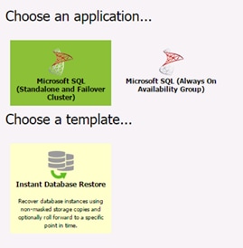
6. Click Source ![]() . From the drop-down menu select Application Browse to select Production site as shown in Figure and an
application server to view available database recovery points. Select resources, and change the order in which the resources are recovered by dragging and dropping the resources in the grid.
Alternatively, select Application Search from the drop-down menu to search for application servers with available recovery points. Add copies to the job definition by clicking Add. Change the order in which the resources are recovered by dragging and dropping the resources in the grid.
. From the drop-down menu select Application Browse to select Production site as shown in Figure and an
application server to view available database recovery points. Select resources, and change the order in which the resources are recovered by dragging and dropping the resources in the grid.
Alternatively, select Application Search from the drop-down menu to search for application servers with available recovery points. Add copies to the job definition by clicking Add. Change the order in which the resources are recovered by dragging and dropping the resources in the grid.
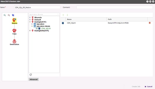
7. Click Copy ![]() . Select Production site to restore from the FlashCopy or the Secondary site to restore from the GlobalMirror copy. By default the latest copy of your data is used. To choose a specific version, Click the Version field as shown in Figure to view specific copies and their associated job and completion time. If recovery from one snapshot fails, another copy from the same site is used. Additional recovery option is available
through the Select Version feature. Enable Allow Point-in-Time selection when job runs to leverage
archived logs and enable a point-in-time recovery of the databases.
. Select Production site to restore from the FlashCopy or the Secondary site to restore from the GlobalMirror copy. By default the latest copy of your data is used. To choose a specific version, Click the Version field as shown in Figure to view specific copies and their associated job and completion time. If recovery from one snapshot fails, another copy from the same site is used. Additional recovery option is available
through the Select Version feature. Enable Allow Point-in-Time selection when job runs to leverage
archived logs and enable a point-in-time recovery of the databases.
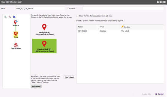
8. Click Destination ![]() . Select a source site and an associated Microsoft SQL database. Click the New database name field to enter an optional alternate name for the database. If the destination is a SQL Failover Cluster instance, select a Windows server proxy in the Select a Windows server to resignature LUNs section. When resignaturing a copy, IBM Spectrum Copy Data Management retains the data and mounts the volume to the proxy selected in the Select a Windows server to resignature LUNs section.
. Select a source site and an associated Microsoft SQL database. Click the New database name field to enter an optional alternate name for the database. If the destination is a SQL Failover Cluster instance, select a Windows server proxy in the Select a Windows server to resignature LUNs section. When resignaturing a copy, IBM Spectrum Copy Data Management retains the data and mounts the volume to the proxy selected in the Select a Windows server to resignature LUNs section.
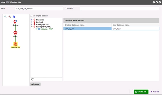
![]() Any Windows node with iSCSI or Fibre Channel access to the storage can be selected as a proxy server, provided that the node is not part of the original cluster. It is recommended to select a standalone virtual or physical Windows node as a proxy server.
Any Windows node with iSCSI or Fibre Channel access to the storage can be selected as a proxy server, provided that the node is not part of the original cluster. It is recommended to select a standalone virtual or physical Windows node as a proxy server.
9. To create the job definition using default options, click Create Job. The job can be run manually from the Jobs ![]() tab.
tab.
10. To edit options before creating the job definition, click Advanced. Set the job definition options.
Application Options
· Roll back uncommitted transactions and leave the database ready to use - Select this option to restore the database to an online state. If selected, additional transaction logs cannot be restored. If deselected, uncommitted transactions are not rolled back, leaving the database non- operational. Additional transaction logs can then be restored.
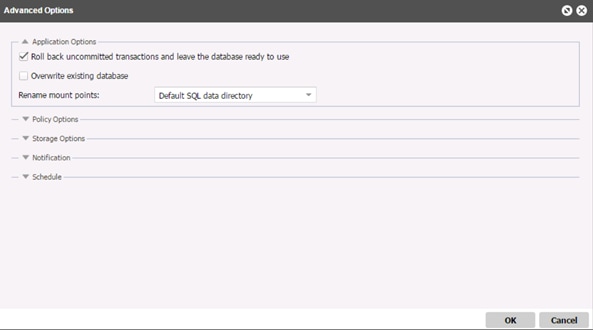
· Overwrite existing database - Select this option to replace an existing database with the same name during recovery. When an Instant Database Recovery is performed for a database and another database with the same name is already running on the destination host/cluster, IBM Spectrum Copy Data Management shuts down the existing database before starting up the recovered database. If this option is not selected, the Instant Database Recovery fails when IBM Spectrum Copy Data Management encounters an existing running database with the same name.
· Rename mount points - By default, IBM Spectrum Copy Data Management renames mount points to the SQL data directory of the target SQL instance. You can override this behavior through the Rename mount points option.
· Default SQL data directory - Mount points are not renamed. Original mount point or drive letter - The original volume mount point of the databases is used. This will keep the same drive mapping, but the database recovery will occur on an alternate server. If the original volume mount point cannot be used to mount a volume (for example, if the folder is not empty), the restore fails.
· Add a custom mount point - If enabled, a custom prefix can be entered in the Prefix string field. The prefix must specify a valid, preexisting volume drive letter that can contain a volume mount point on the drive. The prefix substitutes the default root folder of the mount. For example, if the default root folder of the mount drive is E:\SQLDataFiles\mnt, and F:\RestoreMnt is entered in the Mount Point Prefix field, E:\SQLDataFiles\mnt is renamed to F:\RestoreMnt. The drive, in this case the F drive, must exist on the destination server. If the folder, in this case the RestoreMnt folder, does not exist, it will be created.
Storage Options
· Make Permanent - Set the default permanent restoration action of the job. All database recovery operations can leverage Instant, or Test, mode and then either deleted or promoted to permanent mode. This behavior is controlled through the Make Permanent option.
· Protocol Priority - If more than one storage networking protocol is available, select the protocol to take priority in the job. Available protocols include iSCSI and Fibre Channel.
11. Optionally, expand the Notification section to select the job notification options. From the list of available SMTP resources, select the SMTP Server to use for job status email notifications. If an SMTP server is not selected, an email is not sent.
12. Enter the email addresses of the status email notifications recipients. Click Add ![]() to add it to the list.
to add it to the list.
13. Optionally, expand the Schedule section to select the job scheduling options. Select Start job now to create a job definition that starts the job immediately. Select Schedule job to start at later time to view the list of available schedules. Optionally select one or more schedules for the job. As each schedule is selected, the schedule's name and description displays.
![]() To create and select a new schedule, click the Configure
To create and select a new schedule, click the Configure ![]() tab, then select Schedules
tab, then select Schedules ![]() . Create
a schedule, return to the job editor, refresh the Available Schedules pane, and select the new schedule.
. Create
a schedule, return to the job editor, refresh the Available Schedules pane, and select the new schedule.
14. When you are satisfied that the job-specific information is correct, click Create Job. The job runs as defined by your schedule, or can be run manually from the Jobs ![]() tab as shown below.
tab as shown below.
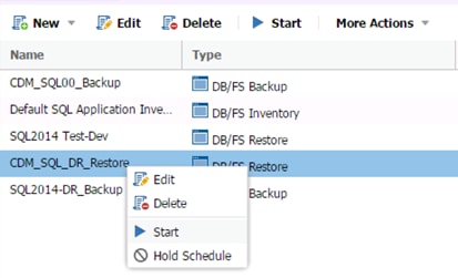
Model MSSQL Application using CloudCenter
The application profile can be created in Cisco CloudCenter in either of two ways as follows:
· Use a base OS image and install packages and applications over the base image through the lifecycle actions in the application profile or through service definition (choose Admin > Services).
· Create an image that contains all the necessary packages and configurations.
The MSSQL application profile used for validation has been created with an image that contains all the necessary packages and configurations. To model the application, complete the following steps:
![]() Image creation and mapping procedure has been described in the “Configure and Setup CloudCenter manager” section above. The image consists of MSSQL package pre-installed.
Image creation and mapping procedure has been described in the “Configure and Setup CloudCenter manager” section above. The image consists of MSSQL package pre-installed.
1. Upload the image template in vCenter. For VMware clouds, virtual machine images are uploaded to vCenter. Application profiles will be created from a snapshot of the image.
2. Define images in Cisco CloudCenter. The user needs to create a new image entity in Infrastructure > Image and link the entity to the actual image path in vCenter.
3. Login to CloudCenter Manager, In the left-hand pane, click the double >> to expand the navigation tray. Select the Applications section.

4. In the main-panel, pre-created Application Profiles will be displayed if any exists. To create a new one, click Model.
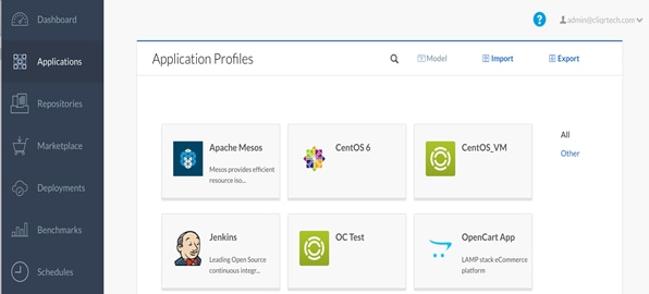
5. When the main-panel refreshes with a list of templates, select N-Tier Execution.
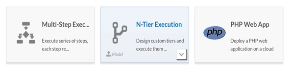
6. The main-panel will now display the modeling tool for creating Application Profiles. The tool defaults to the Topology Modeler tab.

7. In the tool, on the left-hand side, select OS Service and then drag Custom to the canvas of the tool.
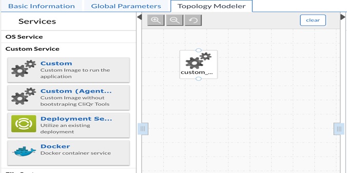
8. In the properties tab, select <Windows2012SQL> as the Base Image that was mapped earlier which consists of MSSQL database installed.
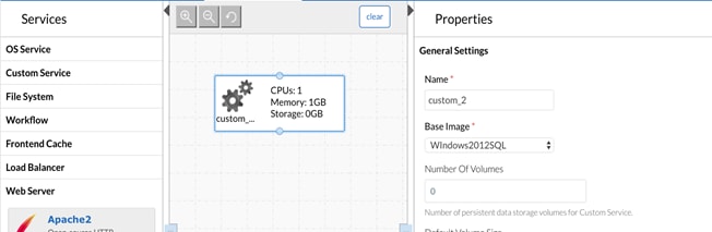
9. Switch to the Basic Information tab of the Application Profile tool (upper left-hand corner of the tool).
10. Name the Application Profile SQL2014. The Version of the Web App is the version of the Application Profile, NOT the image. This allows for users to deploy different versions of the same Application Profile. In this case, the Version is 1.0.
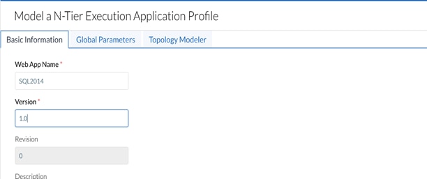
11. The rest of the Basic Information tab will use the default settings, click Save as App to save the application profile.

12. Assuming everything is completed correctly, then the application can now be deployed. In the left-hand pane, click the double >> to expand the navigation tray. Select the Applications section.
13. In the main-panel, click your Application Profile to begin the deployment process.

![]() The process listed above is provided just as a reference; applications will have specific software requirements and all the packages need to be made available to the application profile.
The process listed above is provided just as a reference; applications will have specific software requirements and all the packages need to be made available to the application profile.
Deploy the MSSQL Application on VersaStack Primary Data Center
1. Access the application from the CCM UI and click Applications.
2. Search for the required MSSQL application profile in the Applications page and click the profile to begin the deployment process.

3. When the main-panel refreshes, complete the General Information section. Name the Deployment <MSSQL-Prod> and select <Production> in the dropdown menu for TAGS.

4. Select <Production> tag in Tier Settings and click NEXT.

5. Select the Cloud where we want to deploy the application, in this case its <VersaStack_SVC_Private> cloud.

6. Select the instance type, the size of the VM that needs to be deployed for MSSQL application.
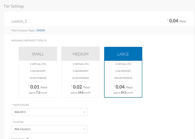
![]() Make sure the ACI Extension is turned off for simplicity.
Make sure the ACI Extension is turned off for simplicity.
7. Click Deploy to start the application deployment process. The deployment process completes when the lights against each tier turns green.
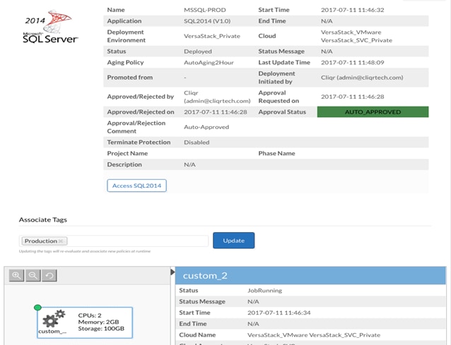
8. The MSSQL VM can be accessed via console using vCenter client or via RDP using IP address.
Deploy the MSSQL Application on VersaStack Secondary Data Center
1. Access the application from the CCM UI and click Applications.
2. Search for the required MSSQL application profile in the Applications page and click the profile to begin the deployment process.

3. When the main-panel refreshes, complete the General Information section. Name the Deployment <MSSQL-TEST> and select <DR_Dev_Test> in the drop-down menu for TAGS.
4. Select <DR_Dev_Test> tag in Tier Settings and click NEXT.
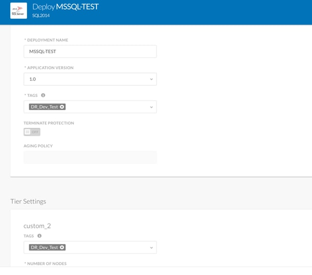
5. Select the Cloud where you want to deploy the application; in this case it is <VersaStack_DR> cloud.
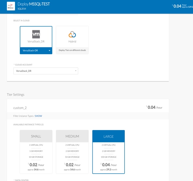
6. Click Deploy to start the application deployment process. The deployment process completes when the lights against each tier turns green.

7. Access the MSSQL application VM via console using vCenter Client or via RDP using the IP address.
Automated Database Restore to the Dev-Test Instance using CDM
Cisco Cloud Center, IBM Spectrum CDM and VersaStack built with IBM Spectrum Virtualize help users drastically improve the Dev-Test and DevOps process by instantly providing copies of application environments and data sets in a virtualized test environment. With IBM Spectrum CDM, users can automate and orchestrate Applications, FlashCopies, and replicas of SQL and Oracle databases of the latest production environment and data, to be instantly stood up in multiple locations. This process facilitates true DevOps efficiency, in a consistent and timely manner. The process provides these benefits:
· The Spectrum CDM REST API provides a unified abstraction of the compute and storage infrastructure, also known as Infrastructure as Code
· Automated workflows for accessing environments and data globally
· Moves organizations closer to a DevOps model
· Continuous development enables higher-quality code, faster
· Ability to implement new technology quicker, which provides a competitive edge
To implement and automate database restore using Spectrum CDM, you can leverage the User interface to create policies and schedule them as described in the section VersaStack Application Protection using IBM Copy Data Management.
You can also leverage the REST API framework to integrate with Cisco Cloud Center and make API calls to register new application resources and initiate Restore jobs. For this workflow, there are two steps involved:
· Register an Application – This step is to agelessly register the application (MSSQL) template that was created by Cisco Cloud Center in the Secondary Data Center
· Run the Restore Job – When the Application server is registered, the Restore job will use a copy of the replicated Production MSSQL database and restore to the newly created MSSQL server
Registering the Application Server through REST
The Application Server Management provides support for registering and managing external application servers and their associated system/application credentials.
Request:
POST /api/appserver
{
"name": "SQL2014r", // application server name
"hostAddress": "172.22.11.33", // ip address of server
"siteId":"1000", // ID of the site
"comment":"from catalog", // comment from user
"catalogEligible":true|false, // boolean, if this flag is on, then HLO will be done against this node
"serverType": “virtual", // if type is virtual, vsphereid must be specified
"vsphereId":"1001", // vcenter where the virtual machine is located, specified only if serverType is virtual
"applicationType":"oracle", // for now only "oracle" is supported
"osType":"windows", // currently only linux is supported
"useKeyAuthentication":false, // if this flag is true, then oskey must be specified
// if the flag is false, then osuser must be specified
"osuser": // specified only if useKeyAuthentication is false
{
"href":"https://172.22.10.66:8443/api/identity/user/1"
}
Response:
201 Created
{
"links": {
"self": {
"rel": "self",
"href": "https://172.22.10.66:8443/api/appserver/1001"
},
"up": {
"rel": "up",
"href": "https://172.22.10.66:8443/api/appserver"
},
"site": {
"rel": "related",
"href": "https://172.22.10.66:8443/api/site/1000",
"title": "Default"
},
"credentials": {
"rel": "related",
"href": "https://172.22.10.66:8443/api/appserver/1001/credential",
},
"usedby": {
"rel": "related",
"href": "https://172.22.10.66:8443/api/endeavour/association/resource/appserver/1001?action=listUsingResources"
}
},
"id":"1001",
"siteId":"1000",
"siteName":"Raleigh(RTP)",
"name": "SQL2014",
"serverType":"virtual",
"vpshereId":"1001",
"osType":"windows"
}
Running MSSQL Restore Job through REST
The example involves a Python script called startusepolicy.py. This script automatically starts a MSSQL restore workflow within IBM Spectrum CDM by taking the name of the job to be restored along with the designated MSSQL server to recover latest snapshot copy cataloged by Spectrum CDM. Additional parameters, such as the Spectrum CDM appliance IP address, user name, and password are also specified at the command line.
"Usage: python startusepolicy.py <scdm ipaddress> <user> <password> <jobname>"
Startusepolicy.py
#
# Example script that uses SCDM REST API to start a Restore Job on SCDM
# Must use Python 2.6+
#
#
import httplib
import base64
import string
import json
import ssl
import urllib2
import time
import sys
if hasattr(ssl, '_create_unverified_context'):
ssl._create_default_https_context = ssl._create_unverified_context
def makegetrest(inurl):
req = urllib2.Request(inurl)
print "Calling HTTP GET "+inurl
req.add_header('x-endeavour-sessionid', sessionid)
rawdata = urllib2.urlopen(req).read()
response = json.loads(rawdata)
return response
def makepost(inurl,data):
print "Calling POST url = " +inurl
req = urllib2.Request(inurl, json.dumps(data), headers={'Content-type': 'application/json', 'Accept': 'application/json'})
req.add_header('x-endeavour-sessionid', sessionid)
response = urllib2.urlopen(req)
rawresponse = response.read()
jsondata = json.loads(rawresponse)
return jsondata
def prettyprint(indata):
print json.dumps(indata, sort_keys=True,indent=4, separators=(',', ': '))
def getsessionid():
url = "/api/endeavour/session"
# base64 encode the username and password
auth = base64.encodestring('%s:%s' % (username, password)).replace('\n', '')
#print 'auth: ', auth
webservice = httplib.HTTPS(host)
# write your headers
webservice.putrequest("POST", url)
webservice.putheader("Host", host)
webservice.putheader("User-Agent", "Python http auth")
webservice.putheader("Content-type", "text/html; charset=\"UTF-8\"")
webservice.putheader("Authorization", "Basic %s" % auth)
webservice.endheaders()
# get the response
statuscode, statusmessage, header = webservice.getreply()
#print "Response: ", statuscode, statusmessage
#print "Headers: ", header
res = webservice.getfile().read()
#print 'Content: ', res
returndata = json.loads(res)
print "getsessionid: "
#prettyprint(returndata)
return(returndata)
def printusage():
print "Usage: python startusepolicy.py <scdm ipaddress> <user> <password> <jobname>"
#
# Main
#
#
# Global variables and get arguments from command line
#
if len(sys.argv)!=5:
printusage()
sys.exit(2)
host=sys.argv[1]+":8443"
username=sys.argv[2]
password=sys.argv[3]
in_jobname=sys.argv[4]
#
# check input parameters
#
if len(host)<1 or len(username)<1 or len(password) <1 or len(in_jobname)<1 :
print "Error command line arguments invalid"
printusage()
sys.exit(2)
#
# generate uniqueid for policy name and job name
#
uniqueid=str(int(time.time()))
#
# Get the session id for scdm authentication
#
sessionresponse=getsessionid()
try:
sessionid = sessionresponse['sessionid']
except Exception, e:
print "Invalide SCDM REST API session id, check username and password"
sys.exit(2)
#
# Traverse the vSphere folder structure to obtain the VM object
#
#
# get list of jobs
#
parsed=makegetrest("https://"+host+"/api/endeavour/job")
recovervmlist=[]
recovervm={}
jobid=""
#
# Find the job id for the Use Data Policy
#
print "Searching for Jobs"
jobs = parsed['jobs']
for job in jobs:
if job['name']==in_jobname:
jobid=job['id']
print "Found JobId="+jobid
print "Found Job With Name="+in_jobname
#
# if we don't have any matching jobs then fail
#
if len(jobid) < 1:
print "Error: No job found with name="+in_jobname
sys.exit(2)
#
# start the job
#
jobinfo={}
startjobresponse=makepost("https://"+host+"/api/endeavour/job/"+jobid+"?action=start",jobinfo)
#prettyprint(startjobresponse)
print "Started Use Data Policy Job with Id="+startjobresponse['id']
This section details the integration of Cisco ACI on VersaStack Private Cloud with Cisco CloudCenter
ACI Setup Requirements
To set up the Private Cloud as a deployment environment, a dedicated ACI tenant named App-A is created to host all the application instances. The application tenant creation is covered in detail in the VersaStack with ACI Design Guide.
To successfully deploy an application, the following requirements must be met:
· An application profile and Tenant need to be pre-provisioned
· A DHCP server needs to be setup to assign IP addresses to the VMs
· The DNS server should be able to resolve the IP addresses for the CloudCenter components
· An L3-Out or Shared L3-Out needs to be setup and VMs should be able to access Internet
For the ACI integration, the following items have already been pre-provisioned on the APIC using VersaStack DC with ACI and IBM SVC design options:
· Tenant (App-A)
· The Tenant that will be used for OpenCart deployment and has L3 access out.
· Virtual Machine Manager (vCenter-VDS)
· Bridge Domain (App-A/BD-Internal)
· Existing Contracts (common/Allow-Shared-L3-Out)
Using these settings, when a new OpenCart application instance is deployed on the Private Cloud, the following items are created:
· Apache Web EPG
· Database EPG
· Contract allowing communication between Web (Apache) and DB (Database) EPGs
· Pre-existing contracts consumed by application tiers to enable communication to L3 network
![]() By default the APIC is shipped with a self-generated certificate that is associated with the common name “APIC.” It is possible to integrate the APIC into a CloudCenter tenant using either the default HTTPS or the non-default HTTP protocol. The integration procedure discussed here use HTTP protocol.
By default the APIC is shipped with a self-generated certificate that is associated with the common name “APIC.” It is possible to integrate the APIC into a CloudCenter tenant using either the default HTTPS or the non-default HTTP protocol. The integration procedure discussed here use HTTP protocol.
1. Login to the APIC using a browser.
2. To configure the APIC for HTTP access, navigate to Fabric -> Fabric Policies -> Pod Policies -> Policies -> Management Access -> default -> HTTP [Admin State] Enabled. When this change is submitted, verify that the APIC responds to HTTP by navigating to the web interface (e.g. http://IP_of_APIC).

3. Create a EPG <CliQr-Services> in pre-provisioned Tenant (App-A) > Application Profile (App-A).
4. Right-click Application EPGs and select Create Application EPG.
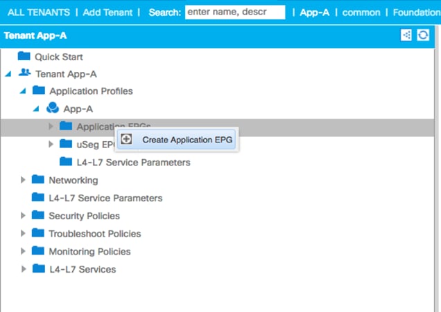
5. Provide <CliQR-Services> as the EPG name and select Unenforced for Intra EPG Isolation and select <BD-APP-A-Internal> as the bridge domain name and click Finish.
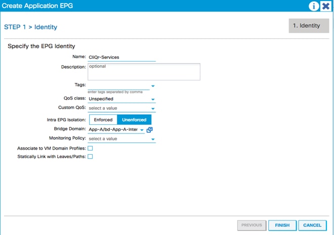
6. To associate VMM domain profile, In the APIC GUI, select and expand Tenant > Tenant (existing Tenant: App-A) > EPG (existing EPG: CliQr-Services).
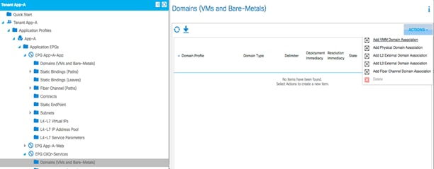
7. From the Domain Profile drop-down list, choose the VMware domain.
8. Change Deployment Immediacy and Resolution Immediacy to Immediate.
9. Click SUBMIT.
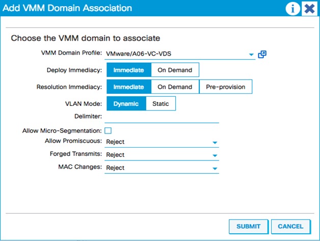
![]() At this point, a new port group has been created on the DVS. To verify, log in to the vSphere Web Client, browse to Networking > DVS, and verify.
At this point, a new port group has been created on the DVS. To verify, log in to the vSphere Web Client, browse to Networking > DVS, and verify.
10. Deploy a DHCP server that will assign IP addresses to the application VMs deployed by CloudCenter and attach it to the <CliQr-Services> port group in vCenter.
11. Login to CloudCenter using a browser.
12. Under the Admin/Infrastructure, click Extensions and then select Add Extension.
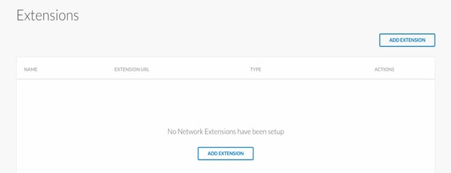
13. Enter the following APIC related information and click Connect. APIC Controller:
URL: Http://192.168.163.10 (APIC IP Address)
Username: (APIC User name)
Password: (APIC password)
Managed Orchestrator: (Orchestrator for VersaStack Private Cloud)
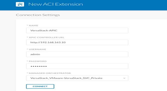
![]() There are various CloudCenter-ACI deployment models available depending on which controller (CCM or APIC) creates the Bridge Domain and application EPGs. Bridge Domain Templates visible in the picture below are used for the deployment model when CCM creates the Bridge Domain in the APIC. We are not using this deployment model in the current setup.
There are various CloudCenter-ACI deployment models available depending on which controller (CCM or APIC) creates the Bridge Domain and application EPGs. Bridge Domain Templates visible in the picture below are used for the deployment model when CCM creates the Bridge Domain in the APIC. We are not using this deployment model in the current setup.
For more information on CloudCenter and Cisco ACI integration please refer to www.cisco.com.
14. Click Save to finish configuring ACI extension.
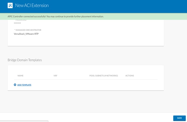
This concludes this task and concludes the integration of CloudCenter with ACI.
In the following task, you will deploy OpenCart application modelled earlier to test this integration. You will be using the APIC created Bridge Domains, and create EPGs and contracts using Cisco CloudCenter.
To deploy the OpenCart application, complete the following steps:
1. In CloudCenter manager, click Applications and select OpenCart application template.
2. In general Settings, provide the deployment name and select the <Production> tag for both the Tiers in OpenCart. Click Next.
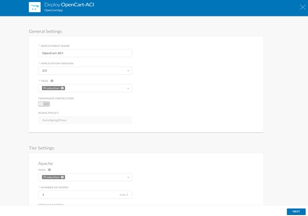
3. In the Tier Settings for both the tiers, Change the USE ACI EXTENSION to On position, Select <VersaStack-APIC> for APIC EXTENSION, <A06-VC-VDS> for the VIRTUAL MACHINE MANAGER and <App-A> for APIC TENANT.
4. Select Cisco ACI for NIC1, New EPG for END POINT GROUP (EPG) TYPE and <bd-App-A-Internal> for the BRIDGE DOMAIN and select the required contracts.
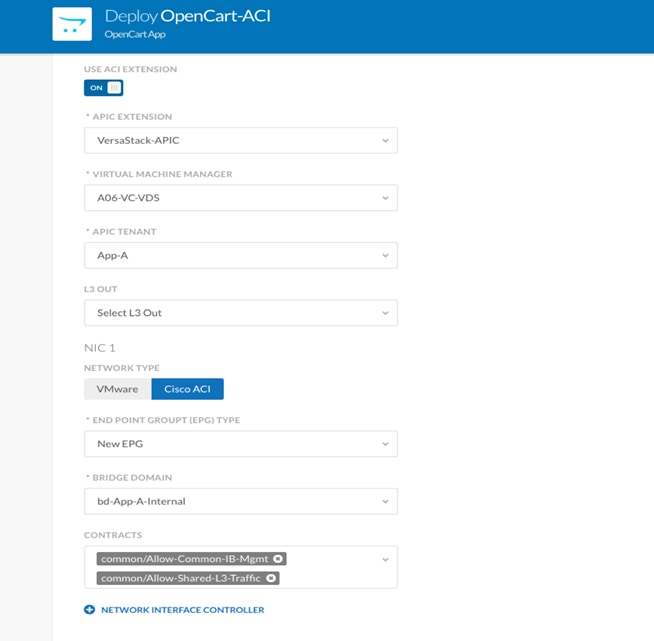
5. Click DEPLOY to initiate the application deployment process.
6. You can check status of the application at any time by selecting option Deployments and verifying the deployment status.
7. As part of the application deployment, we will have two EPG’s created on the APIC for Web frontend and the Database backend tiers of OpenCart and corresponding port groups created in VMware environment on VersaStack.
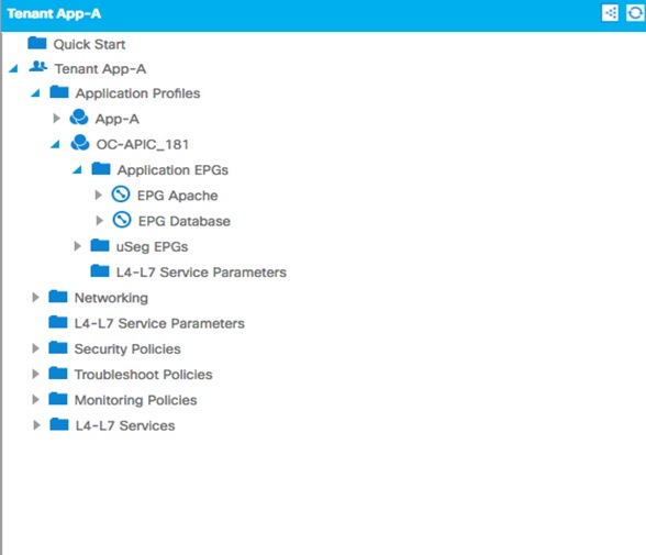
Integrating Cisco CloudCenter with Cisco Prime Service Catalog
Cisco Prime Service Catalog is an optional component in the solution, it offers essential user interface for organizations using automation to deliver data center and application services. It supports a wide range of services, including data center IT, cloud applications, platform applications, and business services such as BYOD or device services. Cisco Prime Service Catalog is a key component of Service Management package of the Cisco ONE Enterprise Cloud Suite, the solution for a software defined data center.
Cisco Prime Service Catalog provides out-of-box integration with Cisco CloudCenter to offer a user-friendly IT service storefront for applications as a service.
Installation of Cisco Prime Services catalog
To download and deploy Cisco Prime Service Catalog Virtual Appliance (OVA) package, complete the following steps:
![]() A detailed installation process is not covered in this document. For detailed information, see the Cisco Prime Services Catalog Installation Guide.
A detailed installation process is not covered in this document. For detailed information, see the Cisco Prime Services Catalog Installation Guide.
1. Download the following zip files from the cisco.com web site per your requirements:
· For application server download CPSC-virtualappliance-as-12.0.0.47.ova.
· For database server use CPSC-virtualappliance-db-12.0.0.35_SIGNED.ovf, The DB server can be downloaded from the below three separate zip files:
- CPSC-virtual-appliance-db-12.0-Part1
- CPSC-virtual-appliance-db-12.0-Part2
- CPSC-virtual-appliance-db-12.0-Part3
2. Create a temporary directory that will contain the contents of the three zip files, for example, "C:\Temp\CPSC_12.0_VA".
3. Extract each of the three zip files into the directory created in the previous step, so that the contents of all three zip files are located in the same directory.
4. From vSphere Client, deploy the OVF file by navigating to the directory containing the extracted files, and select the file "CPSC-virtualappliance-as-12.0.0.47.ova" for application server or "CPSC-virtualappliance-db-12.0.0.35_SIGNED.ovf" for database.
5. After the OVF is deployed as a VM in your VMware vCenter Server, power up the VM.
Integrating CloudCenter
As a Service Administrator, you can add a connection to CloudCenter server, and import Application Profiles and Activation Profiles from CloudCenter database. For each CloudCenter application profile, Prime Service Catalog automatically creates a service.
To integrate CloudCenter with Prime Service Catalog, complete the following steps:
1. From the main menu, choose Advanced Configuration > Integrations and click New Integrations.
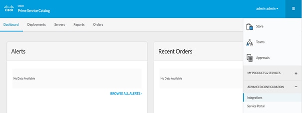
2. Select Cisco CloudCenter.
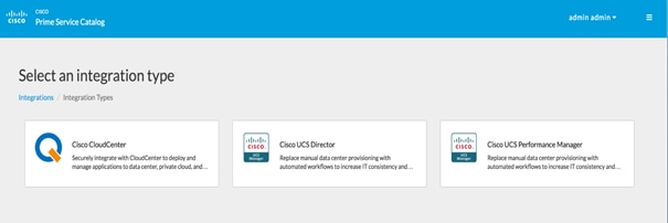
3. Enter the following details and click Create Integration to connect to the CloudCenter server.
4. CloudCenter Host Name or IP Address
· CloudCenter User Name
· API Key
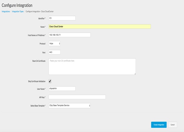
5. Choose Test Connectivity option from Manage Integration drop-down to validate the credentials and the server details.
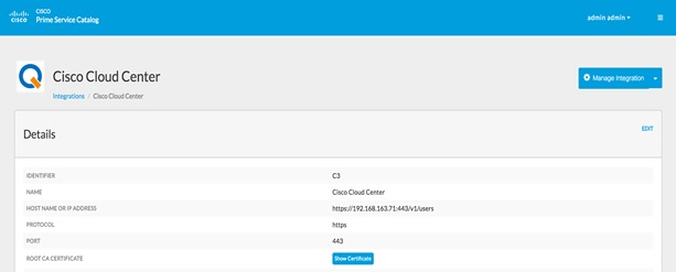
6. Verify that the integration is successful with the following message:

7. After the connection is successful, click Import all Objects option from Manage Integration drop-down. The system starts to discover and import the published CloudCenter application profiles.
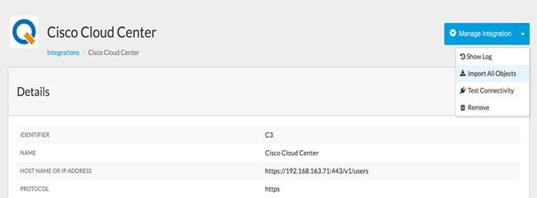
8. In the Discovered panel, you can:
· View all the discovered entities in the Objects tab.
· View the services created for the Application in the Services tab.
9. Select a service and configure the category, presentation, facets, and permissions for these services.

Configuring Permissions and Presentation for CloudCenter Services
Based on the permissions granted to the user, the discovered application services become available in the Service Catalog module. Using the options described in the below procedure you can grant deploying permission of these services to OUs, users, groups or roles in prime Service Catalog, or customize the services by adding more presentation details, descriptions, categories, etc. However, the services are ready to be deployed as is without any additional definitional changes.
CloudCenter Prerequisites
Before you can successfully order application services from Cisco Prime Services Catalog, the following CloudCenter prerequisites must be configured.
![]() Governance has to be turned off for the Prime Services Catalog integration with CloudCenter. Future versions of PSC will not need this to be disabled.
Governance has to be turned off for the Prime Services Catalog integration with CloudCenter. Future versions of PSC will not need this to be disabled.
1. Login to Cisco CloudCenter manager, from Admin > Governance Rules turnoff Governance Rules.
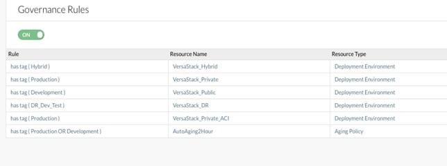
2. Create an activation profile from Admin > Activation Profiles and Clicking on Add Activation Profile. The activation profile will be used when the user created in PSC is pushed to the CloudCenter with proper permissions.
![]() Activation Profiles are pre-defined mapping for each CloudCenter user (and, by association, permissions) and cloud settings (such as enabled clouds, default clouds, etc). When a user is created in PSC, the user is pushed in to CloudCenter and is associated to the default Activation Profile.
Activation Profiles are pre-defined mapping for each CloudCenter user (and, by association, permissions) and cloud settings (such as enabled clouds, default clouds, etc). When a user is created in PSC, the user is pushed in to CloudCenter and is associated to the default Activation Profile.

Create Users in Prime Services Catalog
1. Go back to Cisco Prime Services Catalog as the Service Administrator (or Site Administrator) user.
2. From the main menu, choose Advanced ConfigurationOrganization Designer and click Org Units.
3. Click Add to create an organization unit.
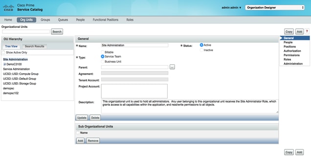
4. Provide a name for the organization unit <demopsc> and click Create.
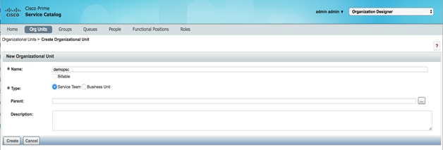
5. Click People tab and create a user <demopsc1>, by providing the details for the user and add the user to the organization unit we created in the above step.
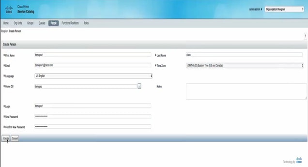
6. Logoff and login back to the prime services catalog using the user we created.
7. Login to CloudCenter manager to verify that the user created in above step is pushed to CloudCenter.
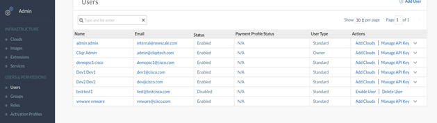
8. Login back to the prime services catalog as administrator.
9. Select the connection from the Integrations page and click Services in the Discovered panel or select Manage Integration option from Settings drop down and click Services in the Discovered panel.
10. Select the service to be customized, we will customize the Service named <CentOS_VM>.

11. In the Details panel, enter Service Name, Description, and add Categories and click Save.

12. In the Presentation panel, click Attach, to select an image to be associated with the service or select Image URL to enter the URL of the image. Default option selected is Image File.
13. Select an image from the list of Select Image window and click Add. Cisco provides a number of images out-of-box that you can assign to the service. You can also upload an image to be used for the service.

14. Enter a description for the service by selecting the Overview or Service Form options, and click Save.
15. In the Facets panel, choose the required options and click Save.
16. In the Permissions panel, do the following:
· Select the roles from the list and click Remove Selected to remove the permission.
· Select from the Add Permissions drop-down list to add or select the roles from the list who can then deploy these services.
17. Click Save. The new service will be displayed in the Service Catalog module based on the category you have selected.
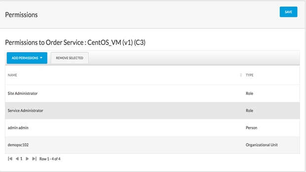
18. The application profile <CentOS_VM> can now be deployed by the <demopsc1> user from PSC.
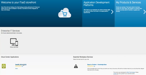
19. Click the <CentOS_VM> application profile available to the user <demopsc1>, while logged in to PSC as the user.
20. Click Order on the next screen.
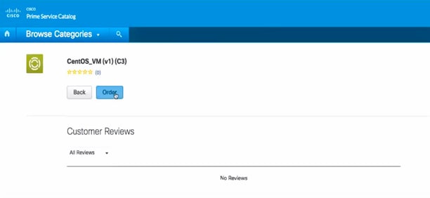
21. Provide deployment details such as the Deployment Name, Cloud, Cloud Account, and the Instance Type.
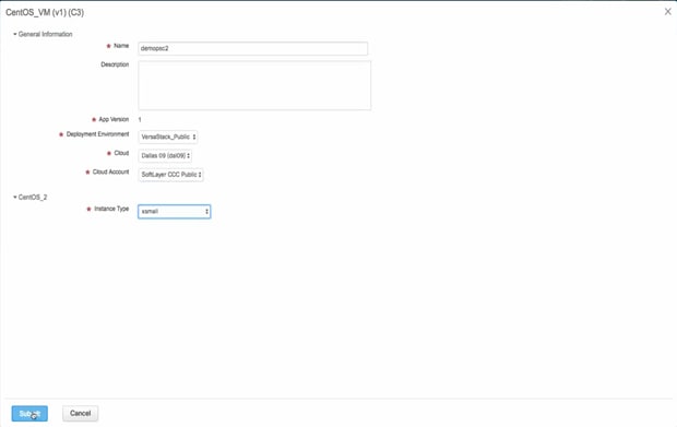
22. The order status can be verified by selecting the order number under the Orders tab.
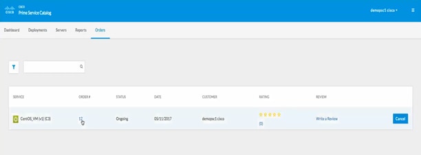
23. The progress of the order can be verified by clicking Order History.
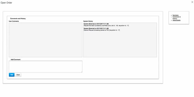
![]() The deployment process will start in CloudCenter.
The deployment process will start in CloudCenter.
24. To verify the deployment status, go to the Deployments section in CloudCenter and wait for the completion.

Sreenivasa Edula, Technical Marketing Engineer, Cisco UCS Data Center Solutions Engineering, Cisco Systems, Inc.
Sreeni has over 18 years of experience in Information Systems with expertise across the Cisco Data Center technology portfolio, including DC architecture design, virtualization, compute, network, storage and cloud computing.
Prashant Jagannathan, Technical Director, Catalogic
Prashant has 10 years of experience in the IT industry. He is part of the Business Development team at Catalogic and is responsible for working with the technical teams of strategic business partners and identifying joint solutions and potential integration in products. Prior to Catalogic, Prashant was a APAC Team lead in Syncsort Inc., where he managed the technical sales operations in the Asia-Pacific region.
Acknowledgements
For their support and contribution to the design, validation and creation of this Cisco Validated Design (CVD), the authors acknowledge:
· Haseeb Niazi, Technical Marketing Engineer, Computing Systems Product Group, Cisco Systems, Inc.
 Feedback