Cisco UCS S3260 M4 Storage Server with Scality RING
Available Languages

Cisco UCS S3260 M4 Storage Server with Scality RING
Design and Deployment of Scality Object Storage on Cisco UCS S3260 M4 Storage Server
Last Updated: June 20, 2018

About the Cisco Validated Design Program
The Cisco Validated Design (CVD) program consists of systems and solutions designed, tested, and documented to facilitate faster, more reliable, and more predictable customer deployments. For more information, visit:
http://www.cisco.com/go/designzone.
ALL DESIGNS, SPECIFICATIONS, STATEMENTS, INFORMATION, AND RECOMMENDATIONS (COLLECTIVELY, "DESIGNS") IN THIS MANUAL ARE PRESENTED "AS IS," WITH ALL FAULTS. CISCO AND ITS SUPPLIERS DISCLAIM ALL WARRANTIES, INCLUDING, WITHOUT LIMITATION, THE WARRANTY OF MERCHANTABILITY, FITNESS FOR A PARTICULAR PURPOSE AND NONINFRINGEMENT OR ARISING FROM A COURSE OF DEALING, USAGE, OR TRADE PRACTICE. IN NO EVENT SHALL CISCO OR ITS SUPPLIERS BE LIABLE FOR ANY INDIRECT, SPECIAL, CONSEQUENTIAL, OR INCIDENTAL DAMAGES, INCLUDING, WITHOUT LIMITATION, LOST PROFITS OR LOSS OR DAMAGE TO DATA ARISING OUT OF THE USE OR INABILITY TO USE THE DESIGNS, EVEN IF CISCO OR ITS SUPPLIERS HAVE BEEN ADVISED OF THE POSSIBILITY OF SUCH DAMAGES.
THE DESIGNS ARE SUBJECT TO CHANGE WITHOUT NOTICE. USERS ARE SOLELY RESPONSIBLE FOR THEIR APPLICATION OF THE DESIGNS. THE DESIGNS DO NOT CONSTITUTE THE TECHNICAL OR OTHER PROFESSIONAL ADVICE OF CISCO, ITS SUPPLIERS OR PARTNERS. USERS SHOULD CONSULT THEIR OWN TECHNICAL ADVISORS BEFORE IMPLEMENTING THE DESIGNS. RESULTS MAY VARY DEPENDING ON FACTORS NOT TESTED BY CISCO.
CCDE, CCENT, Cisco Eos, Cisco Lumin, Cisco Nexus, Cisco StadiumVision, Cisco TelePresence, Cisco WebEx, the Cisco logo, DCE, and Welcome to the Human Network are trademarks; Changing the Way We Work, Live, Play, and Learn and Cisco Store are service marks; and Access Registrar, Aironet, AsyncOS, Bringing the Meeting To You, Catalyst, CCDA, CCDP, CCIE, CCIP, CCNA, CCNP, CCSP, CCVP, Cisco, the Cisco Certified Internetwork Expert logo, Cisco IOS, Cisco Press, Cisco Systems, Cisco Systems Capital, the Cisco Systems logo, Cisco Unified Computing System (Cisco UCS), Cisco UCS B-Series Blade Servers, Cisco UCS C-Series Rack Servers, Cisco UCS S-Series Storage Servers, Cisco UCS Manager, Cisco UCS Management Software, Cisco Unified Fabric, Cisco Application Centric Infrastructure, Cisco Nexus 9000 Series, Cisco Nexus 7000 Series. Cisco Prime Data Center Network Manager, Cisco NX-OS Software, Cisco MDS Series, Cisco Unity, Collaboration Without Limitation, EtherFast, EtherSwitch, Event Center, Fast Step, Follow Me Browsing, FormShare, GigaDrive, HomeLink, Internet Quotient, IOS, iPhone, iQuick Study, LightStream, Linksys, MediaTone, MeetingPlace, MeetingPlace Chime Sound, MGX, Networkers, Networking Academy, Network Registrar, PCNow, PIX, PowerPanels, ProConnect, ScriptShare, SenderBase, SMARTnet, Spectrum Expert, StackWise, The Fastest Way to Increase Your Internet Quotient, TransPath, WebEx, and the WebEx logo are registered trademarks of Cisco Systems, Inc. and/or its affiliates in the United States and certain other countries.
All other trademarks mentioned in this document or website are the property of their respective owners. The use of the word partner does not imply a partnership relationship between Cisco and any other company. (0809R)
© 2018 Cisco Systems, Inc. All rights reserved.
Table of Contents
Cisco Unified Computing System
Cisco UCS S3260 Storage Server
Cisco UCS Virtual Interface Card 1387
Cisco UCS 6300 Series Fabric Interconnect
Local and Geo-Protection Layer
Scale-Out Object Storage Layer
Data Durability and Self-Healing
Software Distributions and Versions
Physical Topology and Configuration
Deployment Hardware and Software
Initial Setup of Cisco UCS 6332 Fabric Interconnects
Configure Fabric Interconnect A
Configure Fabric Interconnect B
Logging into Cisco UCS Manager
Initial Base Setup of the Environment
Enable Fabric Interconnect A Ports for Server
Enable Fabric Interconnect A Ports for Uplinks
Label Servers for Identification
Create LAN Connectivity Policy Setup
Create Maintenance Policy Setup
Create Chassis Firmware Package
Create Chassis Maintenance Policy
Create Chassis Profile Template
Create Chassis Profile from Template
Create Storage Profiles for Cisco UCS S3260 Storage Server
Create Storage Profile for Cisco UCS C220 M4S Rack-Mount Servers
Creating a Service Profile Template for S3260 Storage Server
Create Service Profile Template for Cisco UCS S3260 Storage Server Top and Bottom Node
Identify Service Profile Template
Create Service Profiles from Template
Associating a Service Profile for Cisco UCS S3260 M4 Server
Create Individual RAID0 LUNs for Cisco UCS S3260 Top Loading HDDs
Create Service Profile for Cisco UCS C220 M4S Server for Scality Supervisor Node
Creating Port Channel for Network Uplinks
Create Port Channel for Fabric Interconnect A/B
Configuration of Nexus 9332PQ Switch A and B
Initial Setup of Nexus 9332PQ Switch A and B
Enable Features on Nexus 9332PQ Switch A and B
Configuring VLANs on Nexus 9332PQ Switch A and B
Verification Check of Nexus C9332PQ Configuration for Switch A and B
Installation of Red Hat Enterprise Linux 7.4 Operating System
Installation of RHEL 7.4 on Cisco UCS C220 M4S and Cisco UCS S3260 M4 Server
Preparation of all Nodes for Scality RING Installation
Step 1 - Configuring Network Time Protocol
Functional Testing of NFS Connectors
Functional Testing of S3 Connectors
Appendix A – Kickstart File of Supervisor Node for Cisco UCS C220 M4S
Kickstart File for Supervisor Node
Appendix B – Kickstart File of Storage Nodes for Cisco UCS S3260 M4 Server
Kickstart File for Storage-node1
Cisco Validated Designs consist of systems and solutions that are designed, tested, and documented to facilitate and improve customer deployments. These designs incorporate a wide range of technologies and products into a portfolio of solutions that have been developed to address the business needs of our customers.
Traditional storage models are not optimized for the significant growth rates in unstructured data experienced by the majority of organizations today. These organizations require durable, easy to deploy storage that scales in line with business needs. Enterprises need agile, petabyte-scale access platforms that support growth, reduce complexity and offer cloud-like economics when storing and managing data assets. Distributed file and Object storage solutions provide an increasingly viable alternative in managing these challenges, delivering the following benefits:
· Unlimited linear scalability across scale out file system and object workloads via a broad family of application interfaces such as S3, NFS, SMB, etc.
· Predictable, multi-petabyte, geographically distributed deployment of unstructured data.
· High level of data integrity, storage efficiency and flexibility through replication, erasure coding and geo-distribution achieving 14x9s durability and 100% availability.
· Efficient and cost-effective capacity expansion and server replacement for enhanced overall lifecycle management with automatic data rebalancing and self-healing, avoiding fork-lift upgrades.
· Custom creation and search of metadata for objects.
Traditional enterprise storage systems designed to address business-critical requirements in the data center are clearly not suited for unstructured data use cases such as backup and archive, private and hybrid cloud, video and content distribution, media near line archives, medical imaging, public cloud email and public cloud consumer services workloads etc.
Scality RING is a Software-Defined Storage (SDS) solution that turns a pool of x86 Linux based servers into an unbounded scale-out storage system that delivers petabyte-scale, on-premises unified storage. Providing a ubiquitous storage platform with substantially lower TCO than a traditional storage approach and with the unbundling of software and hardware, Scality RING offers cloud-like economics, assurance of data control and the consolidation of legacy and modern applications at scale, enabling organizations to build web-scale storage infrastructures to meet performance and availability requirements with up to 90% reduction in TCO.
The Cisco UCS S3260 Storage Server, originally designed for the data center, together with Scality RING is optimized for object storage solutions, making it an excellent fit for unstructured data workloads such as backup, archive, and cloud data. The Cisco UCS S3260 delivers a complete infrastructure with exceptional scalability for computing and storage resources together with 40 Gigabit Ethernet networking. The Cisco UCS S3260 is the platform of choice for object storage solutions because it provides more than comparable platforms:
· Proven server architecture that allows you to upgrade individual components without the need for migration
· High-bandwidth networking that meets the needs of large-scale object storage solutions like Scality RING Storage
· Unified, embedded management for easy-to-scale infrastructure
Cisco and Scality are collaborating to offer customers a scalable object storage solution for unstructured data that is integrated with Scality RING Storage. With the power of the Cisco UCS management framework, the solution is cost effective to deploy and manage and will enable the next-generation cloud deployments that drive business agility, lower operational costs and avoid vendor lock-in.
Introduction
Traditional storage systems are limited in their ability to easily and cost-effectively scale to support massive amounts of unstructured data. With about 80 percent of data being unstructured, new approaches using x86 servers are proving to be more cost effective, providing storage that can be expanded as easily as your data grows. Distributed file and object storage is the newest approach for handling massive amounts of data.
Scality is an industry leader in enterprise-class, petabyte-scale storage. Scality introduced a revolutionary software-defined storage platform that could easily manage exponential data growth, ensure high availability, deliver high performance and reduce operational cost. Scality’s scale-out storage solution, Scality RING, is based on patented object storage technology and operates seamlessly on commodity server hardware. It delivers outstanding scalability and data persistence, while its end-to-end parallel architecture provides unsurpassed performance. Scality’s storage infrastructure integrates seamlessly with applications through standard storage protocols such as S3, NFS, and S3.
Scale-out object storage uses x86 architecture storage-optimized servers to increase performance while reducing costs. The Cisco UCS S3260 Storage Server is well suited for distributed file and object-storage solutions. It provides a platform that is cost effective to deploy and manage using the power of the Cisco Unified Computing System (Cisco UCS) management: capabilities that traditional unmanaged and agent-based management systems cannot offer. You can design Cisco UCS S3260 solutions for a computing-intensive, capacity-intensive, or throughput-intensive workload.
Both solutions together, Scality Object Storage and Cisco UCS S3260 Storage Server, deliver a simple, fast and scalable architecture for enterprise scale-out storage .
Solution
This Cisco Validated Design is a simple and linearly scalable architecture that provides object storage solution on Scality RING and Cisco UCS S3260 Storage Server. The solution includes the following features:
· Infrastructure for large scale object storage
· Design of a Scality Object Storage solution together with Cisco UCS S3260 Storage Server
· Simplified infrastructure management with Cisco UCS Manager
· Architectural scalability – linear scaling based on network, storage, and compute requirements
Audience
This document describes the architecture, design and deployment procedures of a Scality Object Storage solution using six Cisco UCS S3260 Storage Server with two C3X60 M4 server nodes each as Storage nodes, one Cisco UCS C220 M4S rackserver as Supervisor node, and two Cisco UCS 6332 Fabric Interconnect managed by Cisco UCS Manager. The intended audience for this document includes, but is not limited to, sales engineers, field consultants, professional services, IT managers, partner engineering, and customers who want to deploy Scality object Storage on the Cisco Unified Computing System using Cisco UCS S3260 Storage Servers.
Solution Summary
This CVD describes in detail the process of deploying Scality Object Storage on Cisco UCS S3260 Storage Server.
The configuration uses the following architecture for the deployment:
· 6 x Cisco UCS S3260 Storage Server with 2 x C3X60 M4 server nodes working as Storage nodes and Connectors.
· 1 x Cisco UCS C220 M4S rack server working as Supervisor node
· 2 x Cisco UCS 6332 Fabric Interconnect
· 1 x Cisco UCS Manager
· 2 x Cisco Nexus 9332PQ Switches
· Scality RING 7.4.0.2
· Redhat Enterprise Linux Server 7.4
Cisco Unified Computing System
The Cisco Unified Computing System is a state-of-the-art data center platform that unites computing, network, storage access, and virtualization into a single cohesive system.
The main components of Cisco Unified Computing System are:
· Computing - The system is based on an entirely new class of computing system that incorporates rack-mount and blade servers based on Intel Xeon Processor E5 and E7. The Cisco UCS servers offer the patented Cisco Extended Memory Technology to support applications with large datasets and allow more virtual machines (VM) per server.
· Network - The system is integrated onto a low-latency, lossless, 40-Gbps unified network fabric. This network foundation consolidates LANs, SANs, and high-performance computing networks which are separate networks today. The unified fabric lowers costs by reducing the number of network adapters, switches, and cables, and by decreasing the power and cooling requirements.
· Virtualization - The system unleashes the full potential of virtualization by enhancing the scalability, performance, and operational control of virtual environments. Cisco security, policy enforcement, and diagnostic features are now extended into virtualized environments to better support changing business and IT requirements.
· Storage access - The system provides consolidated access to both SAN storage and Network Attached Storage (NAS) over the unified fabric. By unifying the storage access the Cisco Unified Computing System can access storage over Ethernet (NFS or iSCSI), Fibre Channel, and Fibre Channel over Ethernet (FCoE). This provides customers with choice for storage access and investment protection. In addition, the server administrators can pre-assign storage-access policies for system connectivity to storage resources, simplifying storage connectivity, and management for increased productivity.
The Cisco Unified Computing System is designed to deliver:
· A reduced Total Cost of Ownership (TCO) and increased business agility.
· Increased IT staff productivity through just-in-time provisioning and mobility support.
· A cohesive, integrated system which unifies the technology in the data center.
· Industry standards supported by a partner ecosystem of industry leaders.
Cisco UCS S3260 Storage Server
The Cisco UCS Storage Server (Figure 1) is a modular, high-density, high-availability, dual node rack server well-suited for service providers, enterprises, and industry-specific environments. It addresses the need for dense cost effective storage for the ever-growing data needs. Designed for a new class of cloud-scale applications, it is simple to deploy and excellent for big data applications, software-defined storage environments, and other unstructured data repositories, media streaming, and content distribution.
Figure 1 The Cisco UCS® S3260 Storage Server
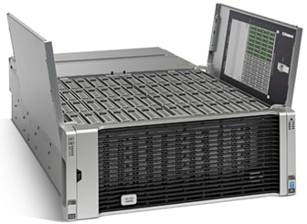
Extending the capability of the Cisco UCS C3000 portfolio, the Cisco UCS S3260 helps you achieve the highest levels of data availability. With dual-node capability that is based on the Intel® Xeon® processor E5-2600 v4 series, it features up to 600 TB of local storage in a compact 4-rack-unit (4RU) form factor. All hard-disk drives can be asymmetrically split between the dual-nodes and are individually hot-swappable. The drives can be built-in in an enterprise-class Redundant Array of Independent Disks (RAID) redundancy or be in a pass-through mode.
This high-density rack server comfortably fits in a standard 32-inch depth rack, such as the Cisco® R42610 Rack.
The Cisco UCS S3260 is deployed as a standalone server in both bare-metal or virtualized environments. Its modular architecture reduces total cost of ownership (TCO) by allowing you to upgrade individual components over time and as use cases evolve, without having to replace the entire system.
The Cisco UCS S3260 uses a modular server architecture that, using Cisco’s blade technology expertise, allows you to upgrade the computing or network nodes in the system without the need to migrate data migration from one system to another. It delivers:
· Dual server nodes
· Up to 36 computing cores per server node
· Up to 60 drives mixing a large form factor (LFF) with up to 14 solid-state disk (SSD) drives plus 2 SSD SATA boot drives per server node
· Up to 512 GB of memory per server node (1 terabyte [TB] total)
· Support for 12-Gbps serial-attached SCSI (SAS) drives
· A system I/O Controller with Cisco VIC 1300 Series Embedded Chip supporting Dual-port 40Gbps
· High reliability, availability, and serviceability (RAS) features with tool-free server nodes, system I/O controller, easy-to-use latching lid, and hot-swappable and hot-pluggable components
Cisco UCS C220 M4 Rack Server
The Cisco UCS® C220 M4 Rack Server (Figure 2) is the most versatile, general-purpose enterprise infrastructure and application server in the industry. It is a high-density two-socket enterprise-class rack server that delivers industry-leading performance and efficiency for a wide range of enterprise workloads, including virtualization, collaboration, and bare-metal applications. The Cisco UCS C-Series Rack Servers can be deployed as standalone servers or as part of the Cisco Unified Computing System™ (Cisco UCS) to take advantage of Cisco’s standards-based unified computing innovations that help reduce customers’ total cost of ownership (TCO) and increase their business agility.
Figure 2 Cisco UCS C220 M4 Rack Server
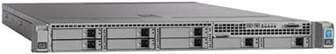
The enterprise-class Cisco UCS C220 M4 rack server extends the capabilities of the Cisco UCS portfolio in a 1RU form factor. It incorporates the Intel® Xeon® processor E5-2600 v4 and v3 product family, next-generation DDR4 memory, and 12-Gbps SAS throughput, delivering significant performance and efficiency gains. The Cisco UCS C220 M4 rack server delivers outstanding levels of expandability and performance in a compact 1RU package:
· Up to 24 DDR4 DIMMs for improved performance and lower power consumption
· Up to 8 Small Form-Factor (SFF) drives or up to 4 Large Form-Factor (LFF) drives
· Support for 12-Gbps SAS Module RAID controller in a dedicated slot, leaving the remaining two PCIe Gen 3.0 slots available for other expansion cards
· A modular LAN-on-motherboard (mLOM) slot that can be used to install a Cisco UCS virtual interface card (VIC) or third-party network interface card (NIC) without consuming a PCIe slot
· Two embedded 1Gigabit Ethernet LAN-on-motherboard (LOM) ports
Cisco UCS Virtual Interface Card 1387
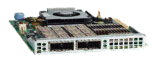
The Cisco UCS Virtual Interface Card (VIC) 1387 (Figure 3) is a Cisco® innovation. It provides a policy-based, stateless, agile server infrastructure for your data center. This dual-port Enhanced Quad Small Form-Factor Pluggable (QSFP) half-height PCI Express (PCIe) modular LAN-on-motherboard (mLOM) adapter is designed exclusively for Cisco UCS C-Series and 3260 Rack Servers. The card supports 40 Gigabit Ethernet and Fibre Channel over Ethernet (FCoE). It incorporates Cisco’s next-generation converged network adapter (CNA) technology and offers a comprehensive feature set, providing investment protection for future feature software releases. The card can present more than 256 PCIe standards-compliant interfaces to the host, and these can be dynamically configured as either network interface cards (NICs) or host bus adapters (HBAs). In addition, the VIC supports Cisco Data Center Virtual Machine Fabric Extender (VM-FEX) technology. This technology extends the Cisco UCS fabric interconnect ports to virtual machines, simplifying server virtualization deployment.
Figure 3 Cisco UCS Virtual Interface Card 1387
The Cisco UCS VIC 1387 provides the following features and benefits:
· Stateless and agile platform: The personality of the card is determined dynamically at boot time using the service profile associated with the server. The number, type (NIC or HBA), identity (MAC address and World Wide Name [WWN]), failover policy, bandwidth, and quality-of-service (QoS) policies of the PCIe interfaces are all determined using the service profile. The capability to define, create, and use interfaces on demand provides a stateless and agile server infrastructure
· Network interface virtualization: Each PCIe interface created on the VIC is associated with an interface on the Cisco UCS fabric interconnect, providing complete network separation for each virtual cable between a PCIe device on the VIC and the interface on the fabric interconnect
Cisco UCS 6300 Series Fabric Interconnect
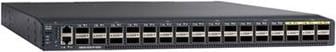
The Cisco UCS 6300 Series Fabric Interconnects are a core part of Cisco UCS, providing both network connectivity and management capabilities for the system (Figure 4). The Cisco UCS 6300 Series offers line-rate, low-latency, lossless 10 and 40 Gigabit Ethernet, Fibre Channel over Ethernet (FCoE), and Fibre Channel functions.
Figure 4 Cisco UCS 6300 Series Fabric Interconnect
The Cisco UCS 6300 Series provides the management and communication backbone for the Cisco UCS B-Series Blade Servers, 5100 Series Blade Server Chassis, and C-Series Rack Servers managed by Cisco UCS. All servers attached to the fabric interconnects become part of a single, highly available management domain. In addition, by supporting unified fabric, the Cisco UCS 6300 Series provides both LAN and SAN connectivity for all servers within its domain.
From a networking perspective, the Cisco UCS 6300 Series uses a cut-through architecture, supporting deterministic, low-latency, line-rate 10 and 40 Gigabit Ethernet ports, switching capacity of 2.56 terabits per second (Tbps), and 320 Gbps of bandwidth per chassis, independent of packet size and enabled services. The product family supports Cisco® low-latency, lossless 10 and 40 Gigabit Ethernet unified network fabric capabilities, which increase the reliability, efficiency, and scalability of Ethernet networks. The fabric interconnect supports multiple traffic classes over a lossless Ethernet fabric from the server through the fabric interconnect. Significant TCO savings can be achieved with an FCoE optimized server design in which network interface cards (NICs), host bus adapters (HBAs), cables, and switches can be consolidated.
The Cisco UCS 6332 32-Port Fabric Interconnect is a 1-rack-unit (1RU) Gigabit Ethernet, and FCoE switch offering up to 2.56 Tbps throughput and up to 32 ports. The switch has 32 fixed 40-Gbps Ethernet and FCoE ports.
Both the Cisco UCS 6332UP 32-Port Fabric Interconnect and the Cisco UCS 6332 16-UP 40-Port Fabric Interconnect have ports that can be configured for the breakout feature that supports connectivity between 40 Gigabit Ethernet ports and 10 Gigabit Ethernet ports. This feature provides backward compatibility to existing hardware that supports 10 Gigabit Ethernet. A 40 Gigabit Ethernet port can be used as four 10 Gigabit Ethernet ports. Using a 40 Gigabit Ethernet SFP, these ports on a Cisco UCS 6300 Series Fabric Interconnect can connect to another fabric interconnect that has four 10 Gigabit Ethernet SFPs. The breakout feature can be configured on ports 1 to 12 and ports 15 to 26 on the Cisco UCS 6332UP fabric interconnect. Ports 17 to 34 on the Cisco UCS 6332 16-UP fabric interconnect support the breakout feature.
Cisco Nexus 9332PQ Switch
The Cisco Nexus® 9000 Series Switches include both modular and fixed-port switches that are designed to overcome these challenges with a flexible, agile, low-cost, application-centric infrastructure.
Figure 5 Cisco 9332PQ
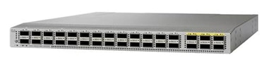
The Cisco Nexus 9300 platform consists of fixed-port switches designed for top-of-rack (ToR) and middle-of-row (MoR) deployment in data centers that support enterprise applications, service provider hosting, and cloud computing environments. They are Layer 2 and 3 nonblocking 10 and 40 Gigabit Ethernet switches with up to 2.56 terabits per second (Tbps) of internal bandwidth.
The Cisco Nexus 9332PQ Switch is a 1-rack-unit (1RU) switch that supports 2.56 Tbps of bandwidth and over 720 million packets per second (mpps) across thirty-two 40-Gbps Enhanced QSFP+ ports
All the Cisco Nexus 9300 platform switches use dual- core 2.5-GHz x86 CPUs with 64-GB solid-state disk (SSD) drives and 16 GB of memory for enhanced network performance.
With the Cisco Nexus 9000 Series, organizations can quickly and easily upgrade existing data centers to carry 40 Gigabit Ethernet to the aggregation layer or to the spine (in a leaf-and-spine configuration) through advanced and cost-effective optics that enable the use of existing 10 Gigabit Ethernet fiber (a pair of multimode fiber strands).
Cisco provides two modes of operation for the Cisco Nexus 9000 Series. Organizations can use Cisco® NX-OS Software to deploy the Cisco Nexus 9000 Series in standard Cisco Nexus switch environments. Organizations also can use a hardware infrastructure that is ready to support Cisco Application Centric Infrastructure (Cisco ACI™) to take full advantage of an automated, policy-based, systems management approach.
Cisco UCS Manager
Cisco UCS® Manager provides unified, embedded management of all software and hardware components of the Cisco Unified Computing System™ (Cisco UCS) across multiple chassis, rack servers and thousands of virtual machines. It supports all Cisco UCS product models, including Cisco UCS B-Series Blade Servers, C-Series Rack Servers, and M-Series composable infrastructure and Cisco UCS Mini, as well as the associated storage resources and networks. Cisco UCS Manager is embedded on a pair of Cisco UCS 6300 or 6200 Series Fabric Interconnects using a clustered, active-standby configuration for high availability. The manager participates in server provisioning, device discovery, inventory, configuration, diagnostics, monitoring, fault detection, auditing, and statistics collection.
Figure 6 Cisco UCS Manager
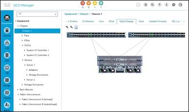
An instance of Cisco UCS Manager with all Cisco UCS components managed by it forms a Cisco UCS domain, which can include up to 160 servers. In addition to provisioning Cisco UCS resources, this infrastructure management software provides a model-based foundation for streamlining the day-to-day processes of updating, monitoring, and managing computing resources, local storage, storage connections, and network connections. By enabling better automation of processes, Cisco UCS Manager allows IT organizations to achieve greater agility and scale in their infrastructure operations while reducing complexity and risk. The manager provides flexible role- and policy-based management using service profiles and templates.
Cisco UCS Manager manages Cisco UCS systems through an intuitive HTML 5 or Java user interface and a command-line interface (CLI). It can register with Cisco UCS Central Software in a multi-domain Cisco UCS environment, enabling centralized management of distributed systems scaling to thousands of servers. UCS Manager can be integrated with Cisco UCS Director to facilitate orchestration and to provide support for converged infrastructure and Infrastructure as a Service (IaaS).
The Cisco UCS XML API provides comprehensive access to all Cisco UCS Manager functions. The API provides Cisco UCS system visibility to higher-level systems management tools from independent software vendors (ISVs) such as VMware, Microsoft, and Splunk as well as tools from BMC, CA, HP, IBM, and others. ISVs and in-house developers can use the XML API to enhance the value of the Cisco UCS platform according to their unique requirements. Cisco UCS PowerTool for Cisco UCS Manager and the Python Software Development Kit (SDK) help automate and manage configurations within Cisco UCS Manager.
Red Hat Enterprise Linux 7.4
Red Hat® Enterprise Linux® is a high-performing operating system that has delivered outstanding value to IT environments for more than a decade. More than 90 percent of Fortune Global 500 companies use Red Hat products and solutions including Red Hat Enterprise Linux. As the world’s most trusted IT platform, Red Hat Enterprise Linux has been deployed in mission-critical applications at global stock exchanges, financial institutions, leading telcos, and animation studios. It also powers the websites of some of the most recognizable global retail brands.
Red Hat Enterprise Linux:
· Delivers high performance, reliability, and security
· Is certified by the leading hardware and software vendors
· Scales from workstations, to servers, to mainframes
· Provides a consistent application environment across physical, virtual, and cloud deployments
Designed to help organizations make a seamless transition to emerging datacenter models that include virtualization and cloud computing, Red Hat Enterprise Linux includes support for major hardware architectures, hypervisors, and cloud providers, making deployments across physical and different virtual environments predictable and secure. Enhanced tools and new capabilities in this release enable administrators to tailor the application environment to efficiently monitor and manage compute resources and security
Scality RING
The Storage market has shifted dramatically in the last few years from one that is dominated by proprietary storage appliances. Scality RING is designed to support a broad variety of application workloads in a capacity-optimized fashion. The data center has evolved from providing mainly back-office transactional services, to providing a much wider range of applications including cloud computing, content serving, distributed computing and archiving.
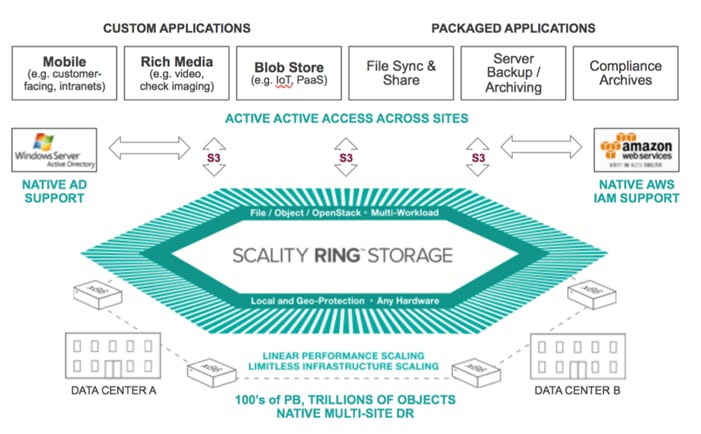
Scality RING software is designed as a distributed, 100 percent parallel, scale-out architecture with a set of intelligent services for data access and presentation, data protection and systems management.
Figure 7 Scality RING Architecture
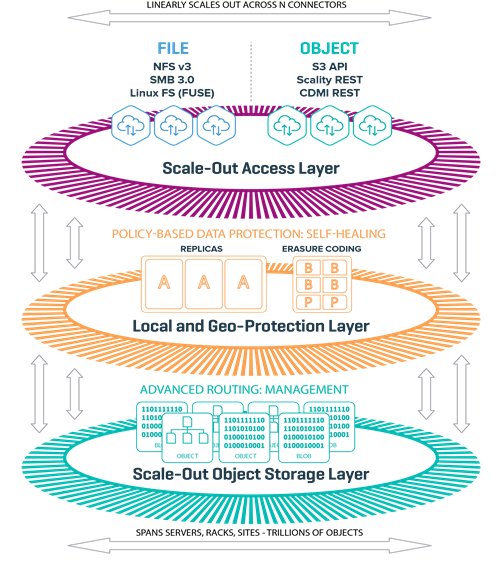
The RING is architected around 3 logical layers:
· Scale-out Access Layer
· Local and Geo Protection Layer
· Scale-out Object Storage Layer
At the heart of the storage layer is a distributed object key/value store, based on peer-to-peer routing protocol.
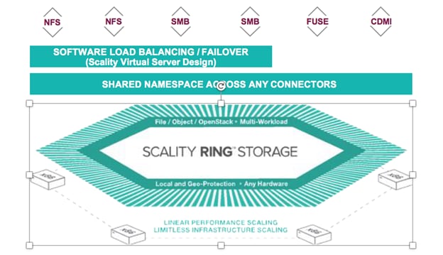
Scale-out Access Layer
The top layer has scalable access services (Connectors) that provide storage protocols for applications.
Figure 8 Scality Scale-out Architecture
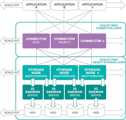
RING Connectors
The Connectors provide the top-level access points and protocol services for applications that use the RING for data storage. Applications may make use of multiple connectors in parallel to scale out the number of operations per second, or the aggregate throughput of the RING for high numbers of simultaneous user connections.
The RING Connectors provide a family of application interfaces including object- based Connectors, the S3 connector that is based on AWS S3, and Scality’s native REST API, as well as file system Connectors (NFS v3, SMB 3.0, and FUSE) to fit a rich set of applications and a wide variety of data types.
Local and Geo-Protection Layer
This layer of the RING contains a set of data protection mechanisms to ensure data durability and integrity, self-healing processes, and a set of systems management and monitoring services.
Data is persisted to the RING using two different protection schemes: Replication and Erasure Coding. These two models are described in more detail in a section below. All data protection is done extemporaneously and not after the fact. When an application receives acknowledgment that the data has been persisted, it means that it has been persisted already and fully protected.
Scale-Out Object Storage Layer
Storage Nodes and IO Daemons
Storage Nodes are virtual processes (Bizstorenode) that own and store a range of objects associated with its portion of the RING’s 'Keyspace'. Each storage server is typically configured with six (6) storage node processes (Bizstorenode), and under these storage nodes are the storage IO daemons (Biziod), which are responsible for persistence of the data on disk, on a standard file system on a local disk. Each Biziod is a low-level process that manages the IO operations to a particular physical disk drive, maintaining the mapping between object ID’s and the actual object locations on disk.
Each Biziod stores object payloads and metadata in a set of fixed size container files on each disk, with the storage daemon providing fast access for storage and retrieval operations into the container files. By containerizing objects, the system can still provide high-performance for small files and avoid the pitfalls of inode and management limits. The RING also leverages low-latency flash (SSD) devices for internal metadata for better performance.
The recommended deployment for systems that have both HDD and SSD media on the storage servers is to deploy a data RING on HDD, and the biziod metadata on SSD. Typically, the requirements for metadata are approximately 1% of the storage capacity of the actual data, so the sizing of SSD should follow that percentage for the best effect.
Scality S3 Connector
The Scality S3 Connector provides an advanced, modern S3 compatible application interface to the Scality RING. The AWS S3 service has become the leading cloud storage service and its API has furthermore emerged as the standard RESTful dialect for object storage, just like NFS was for the NAS generation. This is further amplified by the adoption of S3 among leading new and existing ISV’s who deliver solutions in areas such as Backup and Archive (more traditional consumers of VTL and file-based storage interfaces), sync-n-share, file gateways and data mover solutions, media managers for video and image data and an increasing list of vertical industry solutions.
Rich AWS and Enterprise Security
Support for the full complement of AWS security services, such as multi- tenant accounts, Identity and Access Management (IAM) for users, groups and roles, AWS-style access keys and secret keys, the latest Signature v4 Authentication mechanism, and data encryption. Also featured is interoperability with such existing enterprise security services as LDAP and Microsoft® Active Directory® servers.
S3 API Compatibility
Notwithstanding rapid AWS advancements, a high-degree of S3 API coverage is assured, including core data APIs for Bucket and Object access and Multi-Part-Upload (MPU) for efficient ingest of large objects.
S3 Connector development is based on Continuous Integration (CI) and agile delivery of features when ready, which allows Scality to introduce new S3 methods shortly after their AWS publication. This functionality is provided by the S3 Server, which is supported by Scality as an open source project on GitHub.
Any-to-Any Scale-Out
Applications can access any Bucket or Object from any connector, thus allowing for parallel and multi-user access to data and scaling to billions of buckets and objects. Performance can be scaled-out simply by adding more connectors.
High-Performance Buckets
Support for low-latency response times and high throughput of reads and writes of Objects in Buckets. Also, performance is optimized for fast Bucket listing operations, including fast partial-path search for selected objects by path prefix.
Geo-Distributed Capabilities
S3 Connector provides integrated geo-replication capabilities for storage across multiple datacenters, supporting Active/Active stretched deployments for site disaster protection with continuous data availability and Site/Bucket level replication.
Object Versioning
Scality S3 Connector supports the AWS S3 Bucket Versioning API and follows the functional specifications of the AWS API. Versioning can be enabled and disabled on a per-Bucket basis. By enabling Versioning, the system will retain existing versions of an Object when it is modified. Previous versions of the object are therefore not overwritten but retained in a version history. Object reads will always access the most recent (current) version but can optionally specify a version ID to retrieve a specific older version of the object. This enables data restore capabilities if required in the event of a delete or inadvertent overwrite of the current version.
Ease of Deployment
Delivered as a set of easy-to-deploy Docker containers, installing the S3 Connector is simple, with zero-configuration across the customer’s choice of physical, virtual or cloud environments.
Figure 9 Scality S3 Connector
Scale-Out File System (SOFS)
The RING supports native file system access to RING storage through the file Connectors and the integrated Scale-Out File System (SOFS). SOFS is a POSIX based virtual file system that provides file storage services without the need for external file gateways, as is common in other object storage solutions.
RING utilizes an internal distributed database (MESA) on top of the RING’s storage services. MESA is a distributed database used to store file system directories and inode structures, providing virtual file system hierarchy, with guaranteed transactional consistency of file system data.
The RING provides the concept of “Volumes”, which may be used to easily configure file system services through the Supervisor. The RING can support up to 232 volumes, with support for billions of files per volume.
· Connectors are stateless, can be IP load balanced, and do not lose or corrupt data if they fail
· File system state and INODES are stored in the highly available and durable RING using SSD for performance.
Figure 10 Scality SOFS with Single Namespace and Load Balancing
Data Durability and Self-Healing
The RING is designed to expect and manage a wide range of component failures including disks, servers, networks, and even across multiple data centers, while ensuring that data remains durable and available during these conditions. The RING provides data durability through a set of flexible data protection mechanisms optimized for distributed systems, including replication, erasure coding and geo-replication capabilities that allow applications to select the best data protection strategies for their data.
Replication Class of Service
To optimize data durability in a distributed system, the RING employs local replication, or the storage of multiple copies of an object within the RING. The RING will attempt to spread these replicas across multiple storage nodes, and across multiple disk drives, in order to separate them from common failures. While replication is optimal for many use cases where the objects are small, and access performance is critical, it does impose a high storage overhead penalty compared to the original data.
Scality Erasure Coding
Scality’s Erasure Coding (EC) provides an alternative data protection mechanism to replication that is optimized for large objects and files. The basic idea with erasure coding is to break an object into multiple chunks (m), and apply a mathematical encoding to produce an additional set of parity chunks (k). The resulting set of chunks, (m+k) are then distributed across the RING nodes, providing the ability to access the original object as long as any subset of m data or parity chunks are available. Stated another way, this provides a way to store an object with protection against k failures, with only k/m overhead in storage space.
Replication and EC may be combined, even on a single connector, by configuring a policy for the connector to store objects below a certain size threshold with replication, and files above with a specific EC schema. This allows the application to simply store objects without worrying about the optimal storage strategy per object, with the system managing that automatically.
Self-Healing
The RING provides self-healing operations to automatically resolve component failures, including the ability to rebuild missing data chunks due to disk drive or server failures, rebalance data when nodes leave and join the RING, and to proxy around component failures. In the event a disk drive or even a full server fails, background rebuild operations are spawned to restore the missing object data from its surviving replicas or EC chunks.
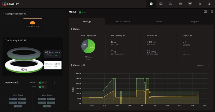
Supervisor Web Management GUI
The Supervisor is the RING’s Web based management GUI. It provides visual, point-and-click style monitoring and management of the RING software, as well as the underlying physical platform layer. The Supervisor provides a main Dashboard page that provides graphical RING views, including the Servers, Zones and Storage Nodes comprising the RING, with browsing capabilities to drill down to details of each component, and pages for operations, management and provisioning of RING services. The Supervisor also provides performance statistics, resource consumption and health metrics through a rich set of graphs.
The Supervisor works in conjunction with the Scality management agent (sagentd), which is hosted on each Scality managed storage server, or connector server. The sagentd daemon provides a single point of communication for the Supervisor with the given host, for purposes of statistics and health metrics collection. This avoids the additional overhead of individual connections from the Supervisor to each Storage Node, and each disk drive daemon running on a specific host.
Figure 11 Supervisor Web GUI
RING 7.4 New Features
For a complete list of new features on RING 7.4 please refer to the Scality documentation located here: http://www.scality.com.
S3 Connector Features
· AWS S3 APIs support
· Vault - AWS Authentication (Signature v4 and v2)
· AWS S3 IAM Support
- Groups
- Policies
- Roles
· Federated Access “Single Sign On” to S3 Connector
· Secure connections over HTTPS/SSL
· Bucket-Level Object Encryption with SafeNet KMS
· S3 Stretched deployments for 2 and 3-sites
· S3 CRR (Cross Regional Replication) for Asynchronous bucket replication
· S3 Bucket Service Utilization API (UTAPI) + Account level Utilization metrics
· IPv6 addresses on external connector interfaces
· Object versioning to track file revisions. The versioning functionality for S3 operations such as PUT, GET and DELETE requests is supported.
· Location Control for compliance and regulatory needs
SOFS Connector Features
· New SOFS Geo Models
- 2-Site Stretched with Witness
- 2-Site Asynchronous Replication
· GEOs Fail Back Improvements
· File Versioning and Versioning Policies
· Volume protection
· Access to File namespace thought S3 API
· Enhanced logging (Volume-level space metering and quota)
· Access to File namespace thought S3 API
Management
· Scality HALO Cloud Monitor
· Disk management tools
· New User Interfaces
- Volume management and monitoring
- S3 monitoring
· S3 Web browser
· Web S3 utilization per users/buckets
· Scality Cloud Monitor integration with the RING
· White branded Service Provider UI
· Disk management tools
Deployment Architecture
The reference architecture use case provides a comprehensive, end-to-end example of deploying Scality object storage on Cisco UCS S3260.
The first section of this Cisco Validated Design covers setting up the Cisco UCS hardware, the Cisco UCS 6332 Fabric Interconnects (Cisco UCS Manager), Cisco UCS S3260 Storage servers, Cisco UCS C220 M4 rack servers, and the peripherals such as Nexus 9332 switches. The second section explains the step–by-step installation instructions for installing Scality RING. The final section includes the functional and High Availability tests on the test bed, Performance, and the best practices evolved while validating the solution.
Figure 12 Cisco UCS SDS Architecture
Solution Overview
This solution is based on Cisco UCS and Scality Object Storage and is divided into multiple sections and covers three main aspects.
Hardware Requirements
This CVD describes the architecture, design and deployment of a Scality Object Storage solution on six Cisco UCS S3260 Storage Servers, each with two Cisco UCS S3260 M4 nodes configured as storage servers and one Cisco UCS C220 M4S rack server as Supervisor node. The whole solution is connected to the pair of Cisco UCS 6332 Fabric Interconnects and to pair of upstream network switch Cisco Nexus 9332PQ.
The detailed configuration is as follows:
· Two Cisco Nexus 9332PQ Switches
· Two Cisco UCS 6332 Fabric Interconnects
· Six Cisco UCS S3260 Storage Servers with two UCS C3X60 M4 server nodes each
· 1 Cisco UCS C220 M4S Rack Servers
![]() Note: Please contact your Cisco representative for country specific information.
Note: Please contact your Cisco representative for country specific information.
Software Distributions and Versions
The required software distribution versions are listed below in Table 1.
| Layer | Component | Version or Release |
| Storage (Chassis) UCS S3260 | Chassis Management Controller | 2.0(13f) |
| Shared Adapter | 4.1(2d) | |
| Compute (Server Nodes) UCS C3X60 M4 | BIOS | C3x60M4.3.0.4b |
| CIMC Controller | 3.0(4a) | |
| Compute (Rack Server) C220 M4S | BIOS | C220M4.3.0.4a |
| CIMC Controller | 3.0(4a) | |
| Network 6332 Fabric Interconnect | UCS Manager | 3.2(3a) |
| Kernel | 5.0(3)N2(3.23a) | |
| System | 5.0(3)N2(3.23a) | |
| Network Nexus 9332PQ | BIOS | 07.59 |
|
| NXOS | 7.0(3)I5(1) |
| Software | Red Hat Enterprise Linux Server | 7.4 (x86_64) |
|
| Scality RING | 7.4.0.2 |
Hardware Requirements
This section contains the hardware components used in the test bed.
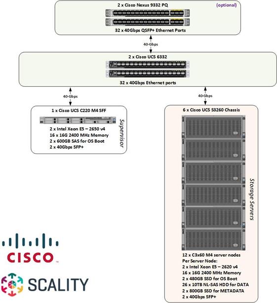
| Component | Model | Quantity | Comments |
| Scality Storage node | Cisco UCS S3260 M4 Chassis | 6 | 2 x UCS C3X60 M4 Server Nodes per Chassis (Total = 12nodes) Per Server Node 2 x Intel E5-2650 v4, 128 GB RAM Cisco 12G SAS RAID Controller 2 x 1.6 TB SSD for OS, 26 x 10TB HDDs for Data, 2 x 800G SSD for Metadata Dual-port 40 Gbps VIC |
| Scality Supervisor Node | Cisco UCS C220M4S Rack server | 1 | · 2 x Intel E5-2683v4, 128 GB RAM · Cisco 12G SAS RAID Controller · 2 x 600 GB SAS for OS · Dual-port 40 Gbps VIC |
| UCS Fabric Interconnects | Cisco UCS 6332 Fabric Interconnects | 2 |
|
| Switches | Cisco Nexus 9332PQ Switches | 2 |
|
|
|
|
|
|
Physical Topology and Configuration
The following sections describe the physical design of the solution and the configuration of each component.
Figure 13 Physical Topology of the Solution
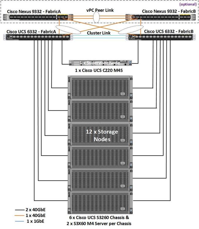
The connectivity of the solution is based on 40 Gbit. All components are connected together via 40 QSFP cables. Between both Cisco Nexus 9332PQ switches are 2 x 40 Gbit cabling. Each Cisco UCS 6332 Fabric Interconnect is connected via 2 x 40 Gbit to each Cisco UCS 9332PQ switch, and each Cisco UCS C220 M4S is connected via 1 x 40 Gbit and each Cisco UCS S3260 M4 server is connected with 2 x 40 Gbit cable to each Fabric Interconnect.
Figure 14 Physical Cabling of the Solution
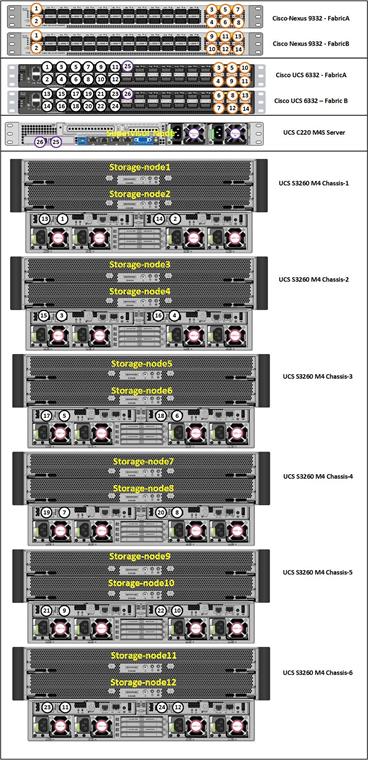
The exact cabling for the Cisco UCS S3260 Storage Server, Cisco UCS C220 M4S, and the Cisco UCS 6332 Fabric Interconnect is illustrated in Table 2.
| Local Device | Local Port | Connection | Remote Device | Remote Port | Cable |
| Cisco Nexus 9332 Switch A | Eth1/1 | 40GbE | Cisco Nexus 9372 Switch B | Eth1/1 | QSFP-H40G-CU1M |
| Eth1/2 | 40GbE | Cisco Nexus 9372 Switch B | Eth1/2 | QSFP-H40G-CU1M | |
| Eth1/17 | 40GbE | Cisco UCS Fabric Interconnect A | Eth1/17 | QSFP-H40G-CU1M | |
| Eth1/18 | 40GbE | Cisco UCS Fabric Interconnect B | Eth1/17 | QSFP-H40G-CU1M | |
| Eth1/23 | 40GbE | Top of Rack (Upstream Network) | Any | QSFP+ 4SFP10G | |
| MGMT0 | 1GbE | Top of Rack (Management) | Any | 1G RJ45 | |
| Cisco Nexus 9332 Switch B | Eth1/1 | 40GbE | Cisco Nexus 9372 Switch B | Eth1/1 | QSFP-H40G-CU1M |
| Eth1/2 | 40GbE | Cisco Nexus 9372 Switch B | Eth1/2 | QSFP-H40G-CU1M | |
| Eth1/17 | 40GbE | Cisco UCS Fabric Interconnect A | Eth1/18 | QSFP-H40G-CU1M | |
| Eth1/18 | 40GbE | Cisco UCS Fabric Interconnect B | Eth1/18 | QSFP-H40G-CU1M | |
| Eth1/23 | 40GbE | Top of Rack (Upstream Network) | Any | QSFP+ 4SFP10G | |
| MGMT0 | 1GbE | Top of Rack (Management) | Any | 1G RJ45 | |
| Cisco UCS 6332 Fabric Interconnect A | Eth1/1 | 40GbE | S3260 Chassis 1 - SIOC 1 (right) | port 1 | QSFP-H40G-CU3M |
| Eth1/2 | 40GbE | S3260 Chassis 1 - SIOC 2 (left) | port 1 | QSFP-H40G-CU3M | |
| Eth1/3 | 40GbE | S3260 Chassis 2 - SIOC 1 (right) | port 1 | QSFP-H40G-CU3M | |
| Eth1/4 | 40GbE | S3260 Chassis 2 - SIOC 2 (left) | port 1 | QSFP-H40G-CU3M | |
| Eth1/5 | 40GbE | S3260 Chassis 3 - SIOC 1 (right) | port 1 | QSFP-H40G-CU3M | |
| Eth1/6 | 40GbE | S3260 Chassis 3 - SIOC 2 (left) | port 1 | QSFP-H40G-CU3M | |
| Eth1/7 | 40GbE | S3260 Chassis 4 - SIOC 1 (right) | port 1 | QSFP-H40G-CU3M | |
| Eth1/8 | 40GbE | S3260 Chassis 4 - SIOC 2 (left) | port 1 | QSFP-H40G-CU3M | |
| Eth1/9 | 40GbE | S3260 Chassis 5 - SIOC 1 (right) | port 1 | QSFP-H40G-CU3M | |
| Eth1/10 | 40GbE | S3260 Chassis 5 - SIOC 2 (left) | port 1 | QSFP-H40G-CU3M | |
| Eth1/11 | 40GbE | S3260 Chassis 6 - SIOC 1 (right) | port 1 | QSFP-H40G-CU3M | |
| Eth1/12 | 40GbE | S3260 Chassis 6 - SIOC 2 (left) | port 1 | QSFP-H40G-CU3M | |
| Eth1/17 | 40GbE | C220 M4S - Server1 - VIC1387 | VIC - Port 1 | QSFP-H40G-CU1M | |
| Eth1/27 | 40GbE | Nexus 9332 A | Eth 1/27 | QSFP-H40G-CU1M | |
| Eth1/28 | 40GbE | Nexus 9332 A | Eth 1/28 | QSFP-H40G-CU1M | |
| Eth1/29 | 40GbE | Nexus 9332 A | Eth 1/29 | QSFP-H40G-CU1M | |
| Eth1/30 | 40GbE | Nexus 9332 B | Eth 1/27 | QSFP-H40G-CU1M | |
| Eth1/31 | 40GbE | Nexus 9332 B | Eth 1/28 | QSFP-H40G-CU1M | |
| Eth1/32 | 40GbE | Nexus 9332 B | Eth 1/29 | QSFP-H40G-CU1M | |
| MGMT0 | 40GbE | Top of Rack (Management) | Any | 1G RJ45 | |
| L1 | 1GbE | UCS 6332 Fabric Interconnect B | L1 | 1G RJ45 | |
| L2 | 1GbE | UCS 6332 Fabric Interconnect B | L2 | 1G RJ45 | |
| Cisco UCS 6332 Fabric Interconnect B | Eth1/1 | 40GbE | S3260 Chassis 1 - SIOC 1 (right) | port 2 | QSFP-H40G-CU3M |
| Eth1/2 | 40GbE | S3260 Chassis 1 - SIOC 2 (left) | port 2 | QSFP-H40G-CU3M | |
| Eth1/3 | 40GbE | S3260 Chassis 2 - SIOC 1 (right) | port 2 | QSFP-H40G-CU3M | |
| Eth1/4 | 40GbE | S3260 Chassis 2 - SIOC 2 (left) | port 2 | QSFP-H40G-CU3M | |
| Eth1/5 | 40GbE | S3260 Chassis 3 - SIOC 1 (right) | port 2 | QSFP-H40G-CU3M | |
| Eth1/6 | 40GbE | S3260 Chassis 3 - SIOC 2 (left) | port 2 | QSFP-H40G-CU3M | |
| Eth1/7 | 40GbE | S3260 Chassis 4 - SIOC 1 (right) | port 2 | QSFP-H40G-CU3M | |
| Eth1/8 | 40GbE | S3260 Chassis 4 - SIOC 2 (left) | port 2 | QSFP-H40G-CU3M | |
| Eth1/9 | 40GbE | S3260 Chassis 5 - SIOC 1 (right) | port 2 | QSFP-H40G-CU3M | |
| Eth1/10 | 40GbE | S3260 Chassis 5 - SIOC 2 (left) | port 2 | QSFP-H40G-CU3M | |
| Eth1/11 | 40GbE | S3260 Chassis 6 - SIOC 1 (right) | port 2 | QSFP-H40G-CU3M | |
| Eth1/12 | 40GbE | S3260 Chassis 6 - SIOC 2 (left) | port 2 | QSFP-H40G-CU3M | |
| Eth1/13 | 40GbE | C220 M4S - Server1 - VIC1387 | VIC -Port2 | QSFP-H40G-CU1M | |
| Eth1/27 | 40GbE | Nexus 9332 A | Eth 1/30 | QSFP-H40G-CU1M | |
| Eth1/28 | 40GbE | Nexus 9332 A | Eth 1/31 | QSFP-H40G-CU1M | |
| Eth1/29 | 40GbE | Nexus 9332 A | Eth 1/32 | QSFP-H40G-CU1M | |
| Eth1/30 | 40GbE | Nexus 9332 B | Eth 1/30 | QSFP-H40G-CU1M | |
| Eth1/31 | 40GbE | Nexus 9332 B | Eth 1/31 | QSFP-H40G-CU1M | |
| Eth1/32 | 40GbE | Nexus 9332 B | Eth 1/32 | QSFP-H40G-CU1M | |
| MGMT0 | 40GbE | Top of Rack (Management) | Any | 1G RJ45 | |
| L1 | 1GbE | UCS 6332 Fabric Interconnect A | L1 | 1G RJ45 | |
| L2 | 1GbE | UCS 6332 Fabric Interconnect A | L2 | 1G RJ45 |
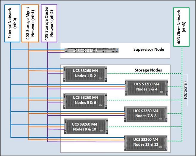
Figure 15 Network Layout of the Solution
Fabric Configuration
This section provides the details to configure a fully redundant, highly available Cisco UCS 6332 fabric configuration:
· Initial setup of the Fabric Interconnect A and B
· Connect to Cisco UCS Manager using virtual IP address of using the web browser
· Launch Cisco UCS Manager
· Enable server and uplink ports
· Start discovery process
· Create pools and policies for service profile template
· Create chassis and storage profiles
· Create Service Profile templates and appropriate Service Profiles
· Associate Service Profiles to servers
Initial Setup of Cisco UCS 6332 Fabric Interconnects
The following section describes the initial setup of the Cisco UCS 6332 Fabric Interconnects A and B.
Configure Fabric Interconnect A
To configure Fabric A, complete the following steps:
1. Connect to the console port on the first Cisco UCS 6332 Fabric Interconnect.
2. At the prompt to enter the configuration method, enter console to continue.
3. If asked to either perform a new setup or restore from backup, enter setup to continue.
4. Enter y to continue to set up a new Fabric Interconnect.
5. Enter n to enforce strong passwords.
6. Enter the password for the admin user.
7. Enter the same password again to confirm the password for the admin user.
8. When asked if this fabric interconnect is part of a cluster, answer y to continue.
9. Enter A for the switch fabric.
10. Enter the cluster name UCS-FI-6332 for the system name.
11. Enter the Mgmt0 IPv4 address.
12. Enter the Mgmt0 IPv4 netmask.
13. Enter the IPv4 address of the default gateway.
14. Enter the cluster IPv4 address.
15. To configure DNS, answer y.
16. Enter the DNS IPv4 address.
17. Answer y to set up the default domain name.
18. Enter the default domain name.
19. Review the settings that were printed to the console, and if they are correct, answer yes to save the configuration.
20. Wait for the login prompt to make sure the configuration has been saved.
Example Setup for Fabric Interconnect A
---- Basic System Configuration Dialog ----
This setup utility will guide you through the basic configuration of
the system. Only minimal configuration including IP connectivity to
the Fabric interconnect and its clustering mode is performed through these steps.
Type Ctrl-C at any time to abort configuration and reboot system.
To back track or make modifications to already entered values,
complete input till end of section and answer no when prompted
to apply configuration.
Enter the configuration method. (console/gui) ? console
Enter the setup mode; setup newly or restore from backup. (setup/restore) ? setup
You have chosen to setup a new Fabric interconnect. Continue? (y/n): y
Enforce strong password? (y/n) [y]: n
Enter the password for "admin":
Confirm the password for "admin":
Is this Fabric interconnect part of a cluster(select 'no' for standalone)? (yes/no) [n]: yes
Enter the switch fabric (A/B): A
Enter the system name: UCS-FI-6332
Physical Switch Mgmt0 IP address : 192.168.10.101
Physical Switch Mgmt0 IPv4 netmask : 255.255.255.0
IPv4 address of the default gateway : 192.168.10.1
Cluster IPv4 address : 192.168.10.100
Configure the DNS Server IP address? (yes/no) [n]: no
Configure the default domain name? (yes/no) [n]: no
Join centralized management environment (UCS Central)? (yes/no) [n]: no
Following configurations will be applied:
Switch Fabric=A
System Name= UCS-FI-6332
Enforced Strong Password=no
Physical Switch Mgmt0 IP Address=192.168.10.101
Physical Switch Mgmt0 IP Netmask=255.255.255.0
Default Gateway=192.168.10.1
Ipv6 value=0
Cluster Enabled=yes
Cluster IP Address=192.168.10.100
NOTE: Cluster IP will be configured only after both Fabric Interconnects are initialized.
UCSM will be functional only after peer FI is configured in clustering mode.
Apply and save the configuration (select 'no' if you want to re-enter)? (yes/no): yes
Applying configuration. Please wait.
Configuration file - Ok
Cisco UCS 6300 Series Fabric Interconnect
UCS-FI-6332-A login:
Configure Fabric Interconnect B
To configure Fabric Interconnect B, complete the following steps:
1. Connect to the console port on the second Cisco UCS 6332 Fabric Interconnect.
2. When prompted to enter the configuration method, enter console to continue.
3. The installer detects the presence of the partner Fabric Interconnect and adds this fabric interconnect to the cluster. Enter y to continue the installation.
4. Enter the admin password that was configured for the first Fabric Interconnect.
5. Enter the Mgmt0 IPv4 address.
6. Answer yes to save the configuration.
7. Wait for the login prompt to confirm that the configuration has been saved.
Example Setup for Fabric Interconnect B
---- Basic System Configuration Dialog ----
This setup utility will guide you through the basic configuration of
the system. Only minimal configuration including IP connectivity to
the Fabric interconnect and its clustering mode is performed through these steps.
Type Ctrl-C at any time to abort configuration and reboot system.
To back track or make modifications to already entered values,
complete input till end of section and answer no when prompted
to apply configuration.
Enter the configuration method. (console/gui) ? console
Installer has detected the presence of a peer Fabric interconnect. This Fabric interconnect will be added to the cluster. Continue (y/n) ? y
Enter the admin password of the peer Fabric interconnect:
Connecting to peer Fabric interconnect... done
Retrieving config from peer Fabric interconnect... done
Peer Fabric interconnect Mgmt0 IPv4 Address: 192.168.10.101
Peer Fabric interconnect Mgmt0 IPv4 Netmask: 255.255.255.0
Cluster IPv4 address : 192.168.10.100
Peer FI is IPv4 Cluster enabled. Please Provide Local Fabric Interconnect Mgmt0 IPv4 Address
Physical Switch Mgmt0 IP address : 192.168.10.102
Apply and save the configuration (select 'no' if you want to re-enter)? (yes/no): yes
Applying configuration. Please wait.
Configuration file - Ok
Cisco UCS 6300 Series Fabric Interconnect
UCS-FI-6332-B login:
Logging into Cisco UCS Manager
To log into Cisco UCS Manager, complete the following steps:
1. Open a Web browser and navigate to the Cisco UCS 6332 Fabric Interconnect cluster address.
2. Click the Launch link to download the Cisco UCS Manager software.
3. If prompted to accept security certificates, accept as necessary.
4. Click Launch UCS Manager HTML.
5. When prompted, enter admin for the username and enter the administrative password.
6. Click Login to log in to the Cisco UCS Manager.
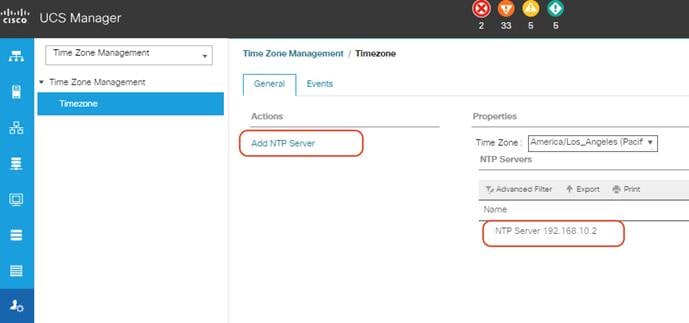
Configure NTP Server
To configure the NTP server for the Cisco UCS environment, complete the following steps:
1. Select Admin tab on the left site.
2. Select Time Zone Management.
3. Select Time Zone.
4. Under Properties select your time zone.
5. Select Add NTP Server.
6. Enter the IP address of the NTP server.
7. Select OK.
Figure 16 Adding a NTP Server - Summary
Initial Base Setup of the Environment
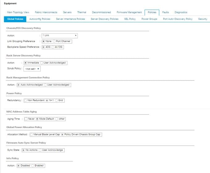
Configure Global Policies
To configure the global policies, complete the following steps:
1. Select the Equipment tab on the left site of the window.
2. Select Policies on the right site.
3. Select Global Policies.
4. Under Chassis/FEX Discovery Policy select Platform Max under Action.
5. Select 40G under Backplane Speed Preference.
6. Under Rack Server Discovery Policy select Immediate under Action.
7. Under Rack Management Connection Policy select Auto Acknowledged under Action.
8. Under Power Policy select Redundancy N+1.
9. Under Global Power Allocation Policy select Policy Driven.
10. Select Save Changes.
Figure 17 Configuration of Global Policies
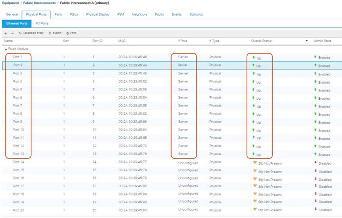
Enable Fabric Interconnect A Ports for Server
To enable server ports, complete the following steps:
1. Select the Equipment tab on the left site.
2. Select Equipment > Fabric Interconnects > Fabric Interconnect A (subordinate) > Fixed Module.
3. Click Ethernet Ports section.
4. Select Ports 1-12, right-click and then select Configure as Server Port for S3260 M4 Chassis to discover and click Yes and then click OK.
5. Select Port 13 for C220 M4S server, right-click and then select “Configure as Server Port” for C220 to discover and click Yes and then click OK.
6. Repeat these steps for Fabric Interconnect B.
Figure 18 Configuration of Server Ports
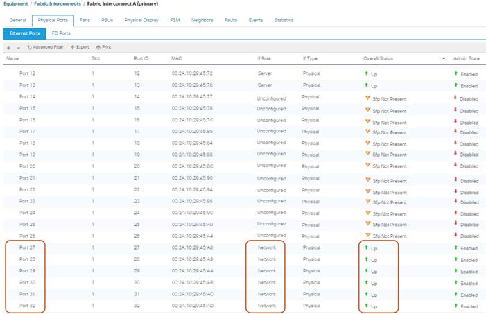
Enable Fabric Interconnect A Ports for Uplinks
To enable uplink ports, complete the following steps:
1. Select the Equipment tab on the left site.
2. Select Equipment > Fabric Interconnects > Fabric Interconnect A (subordinate) > Fixed Module.
3. Click Ethernet Ports section.
4. Select Ports 27-32, right-click and then select Configure as Uplink Port.
5. Click Yes and then OK.
6. Repeat the same steps for Fabric Interconnect B.
Figure 19 Configuring of Network Uplink Ports
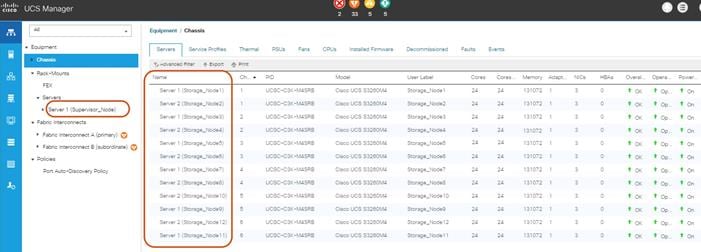
Label Servers for Identification
For a better identification, label each server by completing the following steps:
1. Select the Equipment tab on the left site.
2. Select Chassis > Chassis 1 > Server 1.
3. In the Properties section on the right go to User Label and add Storage-Node1 to the field.
4. Repeat the previous steps for Server 2 of Chassis 1 and for all other servers of Chassis 2 – 6 according to Table 2.
5. Go then to Servers > Rack-Mounts > Servers > and repeat the step for all servers according to Table 3.
| Server | Name |
| Chassis 1 / Server 1 | Storage-Node1 |
| Chassis 1 / Server 2 | Storage-Node2 |
| Chassis 1 / Server 3 | Storage-Node3 |
| Chassis 1 / Server 4 | Storage-Node4 |
| Chassis 1 / Server 5 | Storage-Node5 |
| Chassis 1 / Server 6 | Storage-Node6 |
| Chassis 1 / Server 7 | Storage-Node7 |
| Chassis 1 / Server 8 | Storage-Node8 |
| Chassis 1 / Server 9 | Storage-Node9 |
| Chassis 1 / Server 10 | Storage-Node10 |
| Chassis 1 / Server 11 | Storage-Node11 |
| Chassis 1 / Server 12 | Storage-Node12 |
| Rack-Mount / Server 1 | Supervisor |
Figure 20 Cisco UCS Rack Server Labels
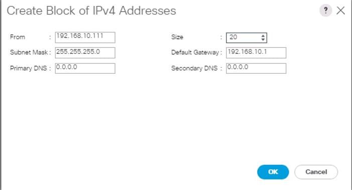
Create KVM IP Pool
To create a KVM IP Pool, complete the following steps:
1. Select the LAN tab on the left site.
2. Go to LAN > Pools > root > IP Pools > IP Pool ext-mgmt.
3. Right-click Create Block of IPv4 Addresses.
4. Enter an IP Address in the From field.
5. Enter Size 20.
6. Enter your Subnet Mask.
7. Fill in your Default Gateway.
8. Enter your Primary DNS and Secondary DNS if needed.
9. Click OK.
Figure 21 Create Block of IPv4 Addresses
Create MAC Pool
To create a MAC Pool, complete the following steps:
1. Select the LAN tab on the left site.
2. Go to LAN > Pools > root > Mac Pools and right-click Create MAC Pool.
3. Type in “Scality-MAC-Pools” for Name.
4. (Optional) Enter a Description of the MAC Pool.
5. Set Assignment Order as Sequential.
6. Click Next.
7. Click Add.
8. Specify a starting MAC address.
9. Specify a size of the MAC address pool, which is sufficient to support the available server resources, for example, 100.
Figure 22 Create a Block of MAC Addresses
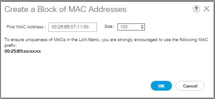
10. Click OK.
11. Click Finish.
Create UUID Pool
To create a UUID Pool, complete the following steps:
1. Select the Servers tab on the left site.
2. Go to Servers > Pools > root > UUID Suffix Pools and right-click Create UUID Suffix Pool.
3. Type in “Scality-UUID-Pools” for Name.
4. (Optional) Enter a Description of the MAC Pool.
5. Set Assignment Order to Sequential and click Next.
6. Click Add.
7. Specify a starting UUID Suffix.
8. Specify a size of the UUID suffix pool, which is sufficient to support the available server resources, for example, 25.
Figure 23 Create a Block of UUID Suffixes
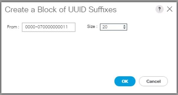
9. Click OK.
10. Click Finish and then OK.
Create VLANs
As mentioned before it is important to separate the network traffic with VLANs for Storage-Management traffic and Storage-Cluster traffic, External traffic and Client traffic (optional). Table 4 lists the configured VLANs.
![]() Note: Client traffic is optional. We used Client traffic, to validate the functionality of NFS and S3 connectors.
Note: Client traffic is optional. We used Client traffic, to validate the functionality of NFS and S3 connectors.
| VLAN | Name | Function |
| 10 | Storage-Management | Storage Management traffic for Supervisor and Storage Nodes |
| 20 | Storage-Cluster | Storage Cluster traffic for Supervisor and Storage Nodes |
| 30 | Client-Network (optional) | Client traffic for Storage Nodes |
| 79 | External-Network | External Public Network for all UCS Servers |
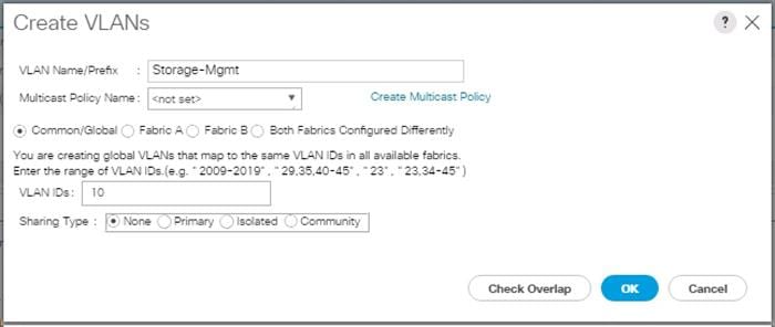
To configure VLANs in the Cisco UCS Manager GUI, complete the following steps:
1. Select LAN in the left pane in the UCSM GUI.
2. Select LAN > LAN Cloud > VLANs and right-click Create VLANs.
3. Enter “Storage-Mgmt” for the VLAN Name.
4. Keep Multicast Policy Name as <not set>.
5. Select Common/Global for Public.
6. Enter 10 in the VLAN IDs field.
7. Click OK and then click Finish.
Figure 24 Create a VLAN
8. Repeat the steps for rest of the VLANs “Storage-Cluster” and “External-Network.”
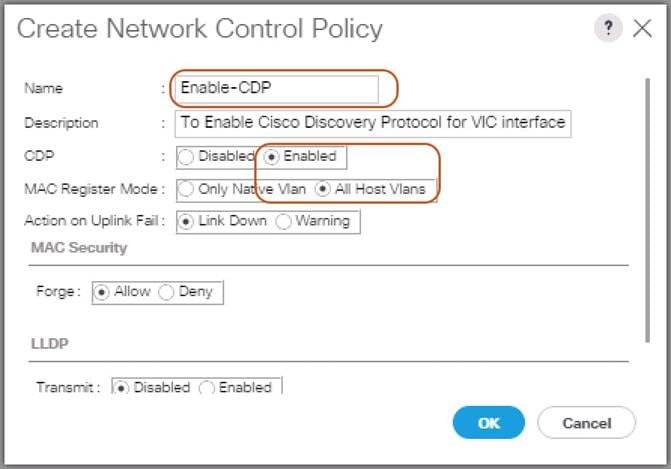
Enable CDP
To enable Network Control Policies, complete the following steps:
1. Select the LAN tab in the left pane of the Cisco UCS Manager GUI.
2. Go to LAN > Policies > root > Network Control Policies and right-click Create Network-Control Policy.
3. Type in Enable-CDP in the Name field.
4. (Optional) Enter a description in the Description field.
5. Click Enabled under CDP.
6. Click All Hosts VLANs under MAC Register Mode.
7. Leave everything else untouched and click OK.
8. Click OK.
Figure 25 Create a Network Control Policy
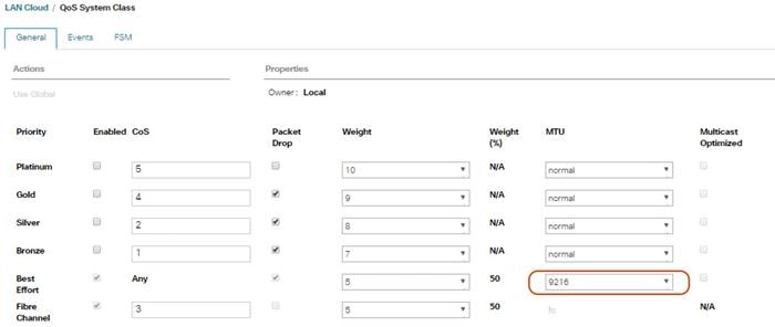
QoS System Class
To create a Quality of Service System Class, complete the following steps:
1. Select the LAN tab in the left pane of the Cisco UCS Manager GUI.
2. Go to LAN > LAN Cloud > QoS System Class.
3. Best Effort MTU as 9216.
4. Set Fibre Channel Weight to None.
5. Click Save Changes and then click OK.
Figure 26 QoS System Class
vNIC Template Setup
Based on the previous section of creating VLANs, the next step is to create the appropriate vNIC templates. For Scality Storage we need to create four different vNICs, depending on the role of the server. Table 5 provides an overview of the configuration.
| vNIC Name | Fabric | Failover | VLAN Name / ID | MTU Size | MAC Pool | Network Control Policy |
| Storage-Mgmt | A | Yes | Storage-Mgmt 10 | 9000 | Scality-MAC-Pools | Enable-CDP |
| Storage-Cluster | B | Yes | Storage-Cluster 20 | 9000 | Scality-MAC-Pools | Enable-CDP |
| External-Network | A | Yes | External-Network 79 | 1500 | Scality-MAC-Pools | Enable-CDP |
To create the appropriate vNICs, complete the following steps:
1. Select the LAN tab in the left pane of the Cisco UCS Manager GUI.
2. Go to LAN > Policies > root > vNIC Templates and right-click Create vNIC Template.
3. Type in Storage-Mgmt in the Name field.
4. (Optional) Enter a description in the Description field.
5. Click Fabric A as Fabric ID and enable failover.
6. Select default as VLANs and click Native VLAN.
7. Select Scality-MAC-Pools as MAC Pool.
8. Select Enable-CDP as Network Control Policy.
9. Click OK and then OK.
Figure 27 Setup of vNIC Template for Storage-Mgmt vNIC
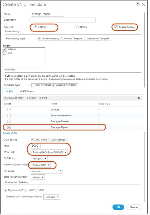
10. Repeat these steps for the vNICs “Storage-Cluster” and “External-Network.” Make sure you select the correct Fabric ID, VLAN and MTU size according to Table 4.
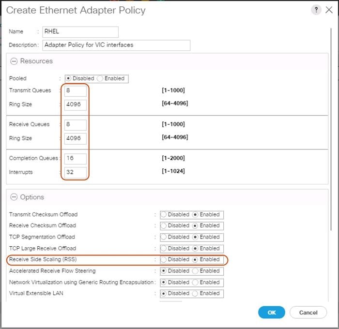
Ethernet Adapter Policy Setup
By default, Cisco UCS provides a set of Ethernet adapter policies. These policies include the recommended settings for each supported server operating system. Operating systems are sensitive to the settings in these policies.
Cisco UCS best practice is to enable Jumbo Frames MTU 9000 for any Storage facing Networks (Storage-Mgmt and Storage-Cluster). Enabling jumbo frames on specific interfaces and modifying Tx and Rx values guarantees 39Gb/s bandwidth on the UCS fabric.
To create a specific adapter policy for Red Hat Enterprise Linux, complete the following steps:
1. Select the Server tab in the left pane of the Cisco UCS Manager GUI.
2. Go to Servers > Policies > root > Adapter Policies and right-click Create Ethernet Adapter Policy.
3. Type in RHEL in the Name field.
4. (Optional) Enter a description in the Description field.
5. Under Resources type in the following values:
a. Transmit Queues: 8
b. Ring Size: 4096
c. Receive Queues: 8
d. Ring Size: 4096
e. Completion Queues: 16
f. Interrupts: 32
6. Under Options enable Receive Side Scaling (RSS).
7. Click OK and then click OK again.
Figure 28 Adapter Policy for RHEL
Boot Policy Setup
To create a Boot Policy, complete the following steps:
1. Select the Servers tab in the left pane.
2. Go to Servers > Policies > root > Boot Policies and right-click Create Boot Policy.
3. Type in a Local-OS-Boot in the Name field.
4. (Optional) Enter a description in the Description field.
Figure 29 Create Boot Policy
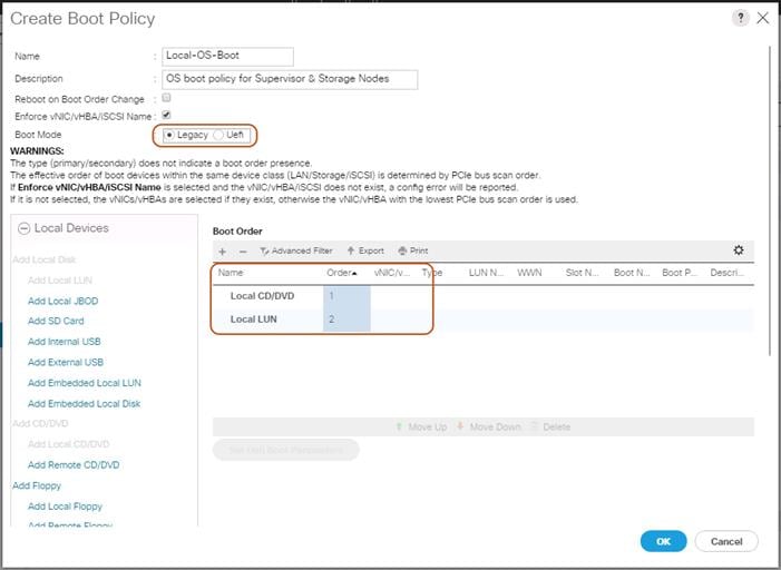
5. Click Local Devices > Add Local CD/DVD and click OK.
6. Click Local Devices > Add Local LUN and Set Type as “Any” and click OK.
7. Click OK.
Create LAN Connectivity Policy Setup
To create a LAN Connectivity Policy, complete the following steps:
1. Select the LAN tab in the left pane.
2. Go to Servers > Policies > root > LAN Connectivity Policies and right-click Create LAN Connectivity Policy for Storage Servers.
3. Type in Storage-Node in the Name field.
4. (Optional) Enter a description in the Description field.
5. Click Add.
6. Type in Storage-Mgmt in the name field.
7. Click “Use vNIC Template.”
8. Select vNIC template for “Storage-Mgmt” from drop-down list.
9. If you are using Jumbo Frame MTU 9000, select the default Adapter Policy, previously created as “RHEL” from the drop-down list.
Figure 30 LAN Connectivity Policy
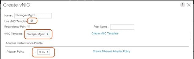
10. Repeat these steps for the remaining networks “Storage-Cluster” and “External-Network.” Make sure you choose Adapter Policy as “RHEL” for VNIC interface “Storage-Cluster.”
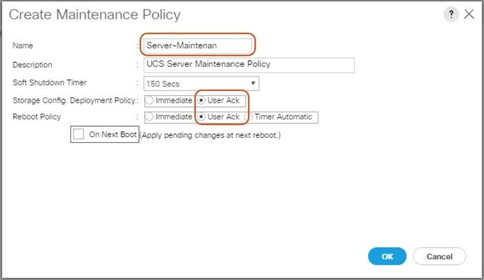
Create Maintenance Policy Setup
To setup a Maintenance Policy, complete the following steps:
1. Select the Servers tab in the left pane.
2. Go to Servers > Policies > root > Maintenance Policies and right-click Create Maintenance Policy.
3. Type in a Server-Maint in the Name field.
4. (Optional) Enter a description in the Description field.
5. Click User Ack under Reboot Policy.
6. Click OK and then click OK again.
7. Create Maintenance Policy
Creating Chassis Profile
The Chassis Profile is required to assign specific disks to a particular server node in a Cisco UCS S3260 Storage Server as well as upgrading to a specific chassis firmware package.
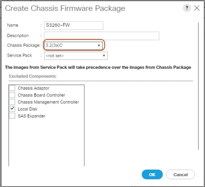
Create Chassis Firmware Package
To create a Chassis Firmware Package, complete the following steps:
1. Select the Chassis tab in the left pane of the Cisco UCS Manager GUI.
2. Go to Chassis > Policies > root > Chassis Firmware Package and right-click Create Chassis Firmware Package.
3. Type in S3260-FW in the Name field.
4. (Optional) Enter a description in the Description field.
5. Select 3.2.(3a)C form the drop-down list of Chassis Package.
6. Select OK and then click OK again.
7. Create Chassis Firmware Package.
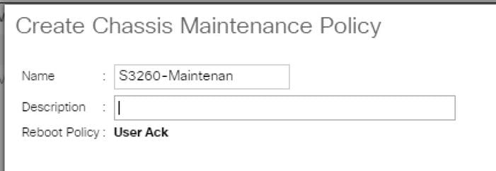
Create Chassis Maintenance Policy
To create a Chassis Maintenance Policy, complete the following steps:
1. Select the Chassis tab in the left pane of the Cisco UCS Manager GUI.
2. Go to Chassis > Policies > root > Chassis Maintenance Policies and right-click Create Chassis Maintenance Policy.
3. Type in S3260-Main in the Name field.
4. (Optional) Enter a description in the Description field.
5. Click OK and then OK.
6. Create Chassis Maintenance Policy.
Create Disk Zoning Policy
To create a Disk Zoning Policy, complete the following steps:
1. Select the Chassis tab in the left pane of the Cisco UCS Manager GUI.
2. Go to Chassis > Policies > root > Disk Zoning Policies and right-click Create Disk Zoning Policy.
3. Type in S3260-DiskZoning in the Name field.
4. (Optional) Enter a description in the Description field.
5. Create Disk Zoning Policy.
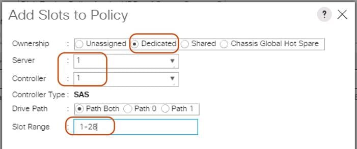
6. Click Add.
7. Select Dedicated under Ownership.
8. Select Server 1 and Select Controller 1.
9. Add Slot Range 1-28 for the top node of the Cisco UCS S3260 Storage Server and click OK.
10. Add Slots to Top Node of Cisco UCS S3260.
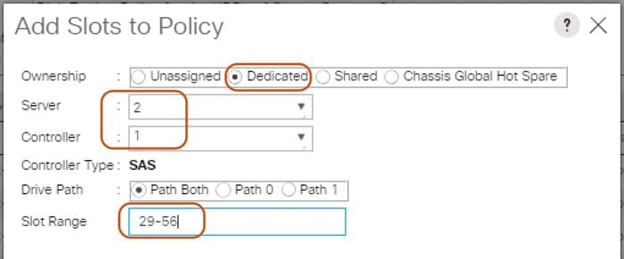
11. Click Add.
12. Select Dedicated under Ownership.
13. Select Server 2 and Select Controller 1.
14. Add Slot Range 29-56 for the bottom node of the Cisco UCS S3260 Storage Server and click OK.
15. Add Slots to Bottom Node of Cisco UCS S3260.
Create Chassis Profile Template
To create a Chassis Profile Template, complete the following steps:
1. Select the Chassis tab in the left pane of the Cisco UCS Manager GUI.
2. Go to Chassis > Chassis Profile Templates and right-click Create Chassis Profile Template.
3. Type in S3260-Chassis in the Name field.
4. Under Type, select Updating Template.
5. (Optional) Enter a description in the Description field.
6. Create Chassis Profile Template
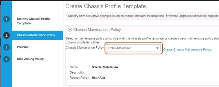
7. Select Next.
8. Under the radio button Chassis Maintenance Policy, select your previously created Chassis Maintenance Policy.
Figure 31 Chassis Profile Template – Chassis Maintenance Policy
9. Select Next.
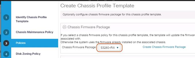
10. Select the + button and select under Chassis Firmware Package your previously created Chassis Firmware Package Policy.
Figure 32 Chassis Profile Template – Chassis Firmware Package
11. Select Next.
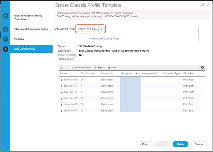
12. Under Disk Zoning Policy select your previously created Disk Zoning Policy.
Figure 33 Chassis Profile Template – Disk Zoning Policy
13. Click Finish and then click OK again.
Create Chassis Profile from Template
To create the Chassis Profiles from the previous created Chassis Profile Template, complete the following steps:
1. Select the Chassis tab in the left pane of the Cisco UCS Manager GUI.
2. Go to Chassis > Chassis Profile Templates and select “S3260-Chassis” you created previously.
3. Then right click to select “Create Chassis Profiles from Template."
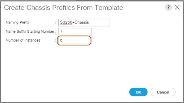
4. Type in S3260-Chassis in the Name field.
5. Leave the Name Suffix Starting Number untouched.
6. Enter 6 for the Number of Instances for all connected Cisco UCS S3260 Storage Server.
7. Click OK.
Associate Chassis Profile
To associate all previous created Chassis Profile, complete the following steps:
1. Select the Chassis tab in the left pane of the Cisco UCS Manager GUI.
2. Go to Chassis > Chassis Profiles and select “S3260-Chassis1.”
3. Right-click Change Chassis Profile Association.
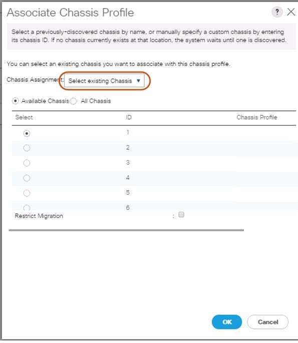
4. Under Chassis Assignment, choose Select existing Chassis from the drop-down list.
5. Under Available Chassis, select ID 1.
6. Click OK and then click OK again.
7. Repeat the steps for the other four Chassis Profiles by selecting the IDs 2 – 6.
Figure 34 Associate Chassis Profile
Creating Storage Profiles
Setting Disks for Cisco UCS S3260 M4 Servers and Cisco UCS C220 M4 Rack-Mount Servers to Unconfigured-Good
To prepare the OS drives reserved from the Rack-Mount servers for storage profiles, make sure the disks have to be converted from “JBOD” to “Unconfigured-Good”. To convert the disks, complete the following steps:
1. Select the Equipment tab in the left pane of the Cisco UCS Manager GUI.
2. For S3260 M4 servers, Go to Equipment -> Chassis -> Chassis1 -> Servers -> Server1 -> Inventory -> Storage -> Disks
3. Select both disks from slot “201 and 202” and right-click “Set JBOD to Unconfigured-Good”.
4. For C220 M4S servers, Go to Equipment -> Rack-Mounts -> Servers -> Server1 -> Inventory -> Storage -> Disks
5. Select both disks from slot “201 and 202” and right-click “Set JBOD to Unconfigured-Good”.
Create Storage Profiles for Cisco UCS S3260 Storage Server
To create the Storage Profile for the top node of the Cisco UCS S3260 Storage Server, complete the following steps:
1. Select Storage in the left pane of the Cisco UCS Manager GUI.
2. Go to Storage > Storage Profiles and right-click Create Storage Profile.
3. Type in S3260-TopNode in the Name field.
4. (Optional) Enter a description in the Description field.
5. Click Add.
6. Type in “OS-Boot” in the Name field.
7. Configure as follows:
a. Create Local LUN
b. Size (GB) = 1
c. Fractional Size (MB) = 0
d. Auto Deploy
e. Select Expand To Available
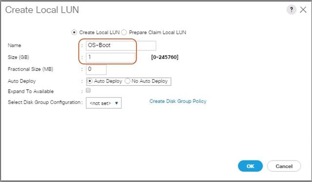
8. Click “Create Disk Group Policy” to Create RAID1 LUN.
9. Type in RAID1-S3260 in the Name field.
10. (Optional) Enter a description in the Description field.
11. RAID Level = RAID 1 Mirrored.
12. Select Disk Group Configuration (Manual).
13. Click Add.
14. Type in 201 for Slot Number.
15. Click OK and then again Add.
16. Type in 202 for Slot Number.
17. Leave everything else untouched.
18. Click OK and then OK.
Figure 35 Create Disk Group Policy
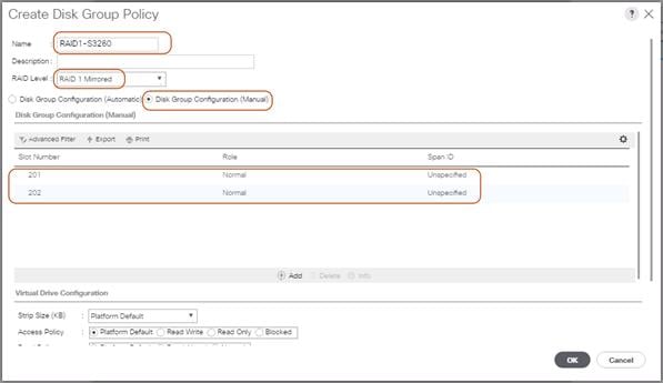
19. Select your previously created Disk Group Policy for the Boot SSDs with the radio button under Select Disk Group Configuration.
20. Select Disk Group Configuration.
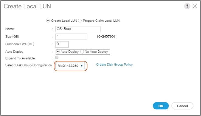
21. Click OK, click OK again, and then click OK.
Figure 36 Storage Profile for the Top Node of Cisco UCS S3260 Storage Server
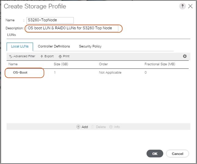
21. Repeat these steps to create the Storage Profile for the bottom Node of the Cisco UCS S3260 Storage Server and name it “S3260-BottomNode.”
Create Storage Profile for Cisco UCS C220 M4S Rack-Mount Servers
To create a Storage Profile for the Cisco UCS C220 M4S, complete the following steps:
1. Select Storage in the left pane of the UCSM GUI.
2. Go to Storage > Storage Profiles and right-click Create Storage Profile.
3. Type in C220-OS-RAID1 in the Name field.
4. (Optional) Enter a description in the Description field.
5. Click Add.
Figure 37 Create Storage Profile for Cisco UCS C220 M4S
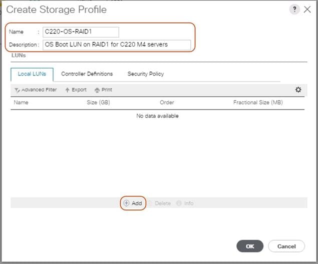
22. Type in Boot in the Name field.
23. Configure as follows:
a. Create Local LUN
b. Size (GB) = 1
c. Fractional Size (MB) = 0
d. Select Expand To Available
e. Auto Deploy
Figure 38 Create Local LUN
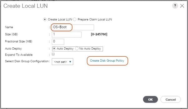
24. Click Create Disk Group Policy to Create RAID1 LUN.
25. Type in RAID1-C220 in the Name field.
26. (Optional) Enter a description in the Description field.
27. RAID Level = RAID 1 Mirrored.
28. Select Disk Group Configuration (Manual).
29. Click Add.
30. Type in 1 for Slot Number.
31. Click OK and then again Add.
32. Type in 2 for Slot Number.
33. Leave everything else untouched. Click OK and then click OK again.
Figure 39 Create Disk Group Policy for Cisco UCS C220 M4S
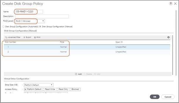
34. Select your previously created Disk Group Policy for the C220 M4S Boot Disks with the radio button under Select Disk Group Configuration.
Figure 40 Create Disk Group Configuration for Cisco UCS C220 M4S
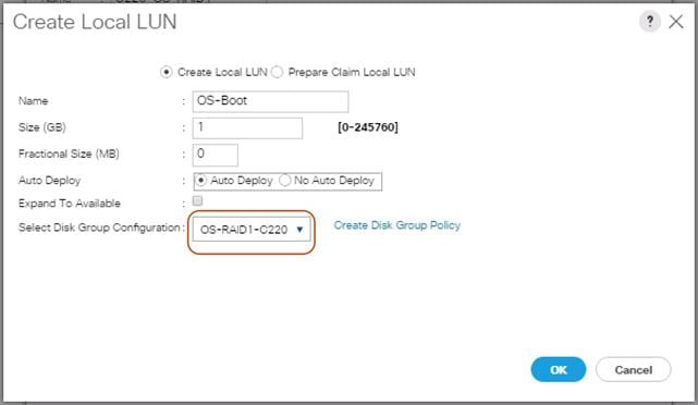
35. Click OK and then OK and again click OK.
Creating a Service Profile Template for S3260 Storage Server
Create Service Profile Template for Cisco UCS S3260 Storage Server Top and Bottom Node
To create a Service Profile Template, complete the following steps:
1. Select Servers in the left pane of the Cisco UCS Manager GUI.
2. Go to Servers > Service Profile Templates > root and right-click Create Service Profile Template.
Identify Service Profile Template
To identify the Service Profile template, complete the following steps:
1. Type in “Storage-TopNode-Template” in the Name field.
2. In the UUID Assignment section, select the UUID Pool you created in the beginning.
3. (Optional) Enter a description in the Description field.
Figure 41 Identify Service Profile Template
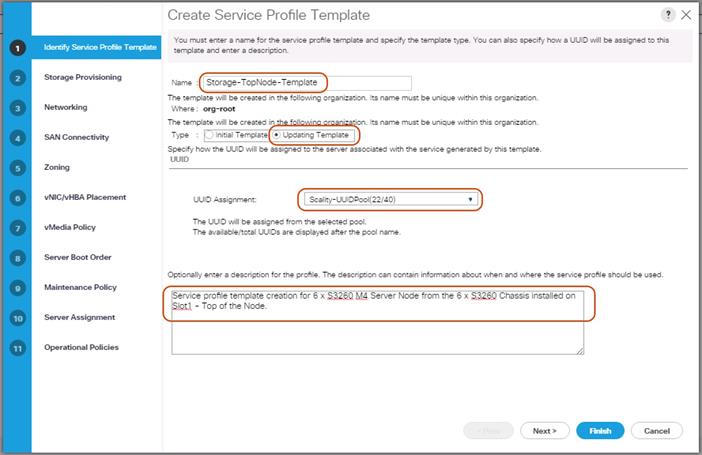
4. Click Next.
Storage Provisioning
To provision the storage profile, complete the following steps:
1. Go to the Storage Profile Policy tab and select the Storage Profile S3260-TopNode for the top node of the Cisco UCS S3260 Storage Server you created before.
2. Click Next.
Figure 42 Storage Provisioning
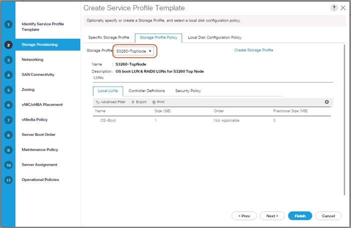
Networking
1. Keep the Dynamic vNIC Connection Policy field at the default.
2. Select LAN connectivity to Use Connectivity Policy created before.
3. From LAN Connectivity drop down list, select “Storage-Node” created before and click Next.
Figure 43 Summary Networking
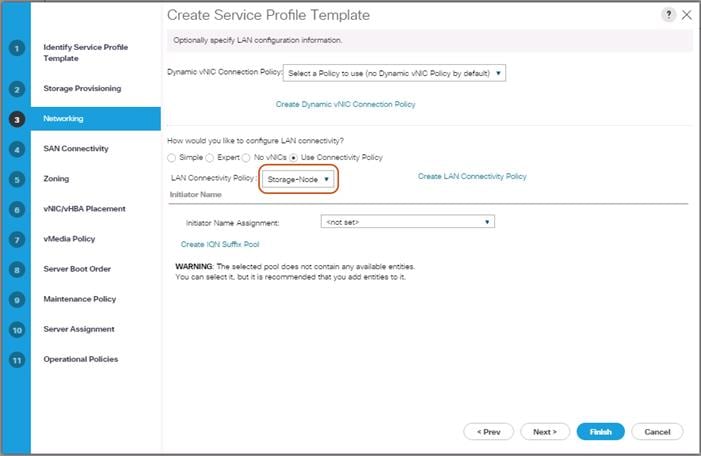
3. Click Next to continue with SAN Connectivity.
4. Select No vHBA for How would you like to configure SAN Connectivity?
5. Click Next to continue with Zoning.
6. Click Next.
vNIC/vHBA Placement
1. Select Let system Perform placement form the drop-down list.
2. Under PCI order section, Sort all the vNICs.
3. Make sure the vNICs order are listed as External-Network > 1, then followed by Storage-Mgmt > 2 and Storage-Cluster > 3.
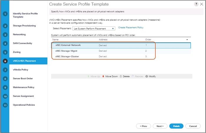
4. Click Next to continue with vMedia Policy.
5. Click Next.
Server Boot Order
1. Select the Boot Policy “S3260-Boot” you created before under Boot Policy.
2. Server Boot Order.
3. Click Next.
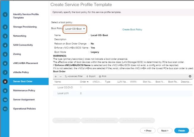
Maintenance Policy
1. Select the Maintenance Policy you created before under Maintenance Policy.
Figure 44 Maintenance Policy
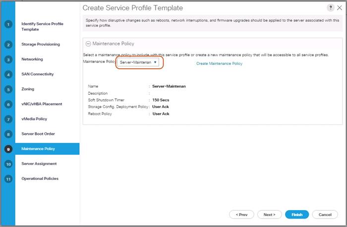
2. Click Next.
3. Under Server Assignment, Leave everything else untouched.
4. Click Next.
Operational Policies
1. Click Finish and then click OK.
2. Repeat the steps for the bottom node of the Cisco UCS S3260 Storage Server by naming template as “Storage-BottomNode-Template.”
3. During Storage Provisioning tab, choose the Storage Profile for the bottom node “S3260-BottomNode” you created previously.
Create Service Profiles from Template
This section details how to create the appropriate Service Profiles from the previous Service Profile Templates. To create the first profile for the top node of the Cisco UCS S3260 Storage Server, complete the following steps:
1. Select Servers from the left pane of the Cisco UCS Manager GUI.
2. Go to Servers > Service Profiles and right-click Create Service Profile from Template.
3. Type in Storage-Node1 in the Name Prefix field.
4. Choose “Storage-TopNode-Template” as the Service Profile Template you created before for the top node of the Cisco UCS S3260 Storage Server.
5. Click OK and then click OK again.
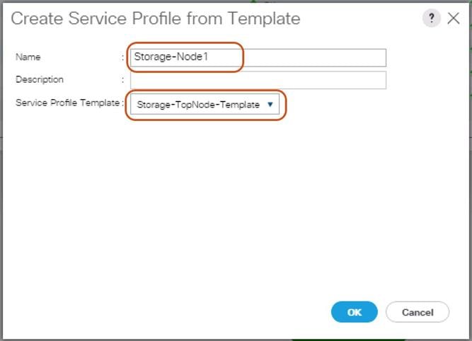
6. Repeat these steps to create Service Profiles for the remaining S3260 M4 server top Nodes from the Template that belongs to top Node “Storage-TopNode-Template”. Make sure you name it as “Storage-Node3, Storage-Node5, Storage-Node7, Storage-Node9 and Storage-Node11” respectively.
7. For the remaining M4 nodes, again Navigate to Servers > Service Profiles and right-click Create Service Profile from Template.
8. Type in Storage-Node2 in the Name Prefix field.
9. Choose “Storage-BottomNode-Template” as the Service Profile Template you created before for the top node of the Cisco UCS S3260 Storage Server.
10. Click OK and then click OK again.
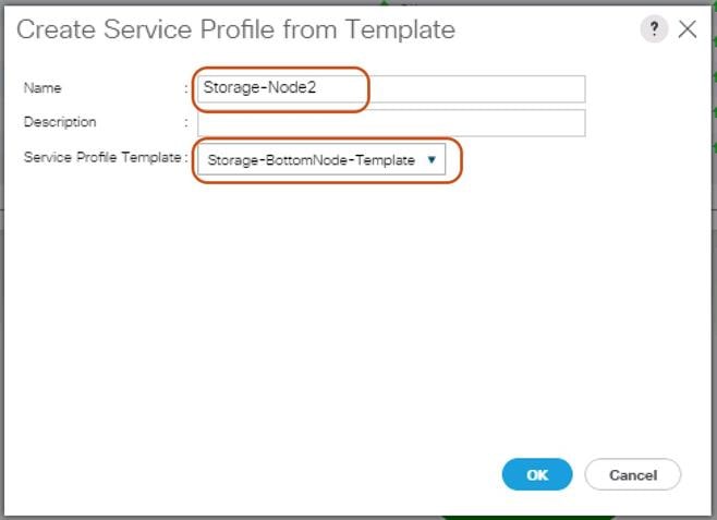
11. Repeat these steps to create Service Profiles for the remaining S3260 M4 server Bottom Nodes from the Template that belongs to bottom Node “Storage-BottomNode-Template”. Make sure you name it as “Storage-Node4, Storage-Node6, Storage-Node8, Storage-Node10, and Storage-Node12” respectively.
Associating a Service Profile for Cisco UCS S3260 M4 Server
To associate all the “Storage-NodeX” Service Profiles to the Cisco UCS S3260 M4 Storage Servers, complete the following steps:
1. Select Servers from the left pane of the Cisco UCS Manager GUI.
2. Go to Servers > Service Profiles and right-click “Storage-Node1” Service profile created previously.
3. Click “Change Server Profile Association.”
4. From the Server Assignment drop-down list choose “Select Existing Server.”
5. Click the radio button “Available Servers.”
6. From the Chassis and Slot listed, choose Chassis1/Slot1 for Storage-Node1.
7. Click OK.
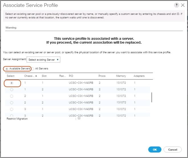
8. Repeat these steps to the Associate Remaining Service profiles “Storage-NodeX” for the Cisco UCS S3260 M4 storage server as shown in the table below.
| Service Profile Template | Service Profile | S3260 Chassis | Server Slot ID | |
| Storage-TopNode-Template | Storage-Node1 | 1 | 1 | |
| Storage-BottomNode-Template | Storage-Node2 | 1 | 2 | |
| Storage-TopNode-Template | Storage-Node3 | 2 | 1 | |
| Storage-BottomNode-Template | Storage-Node4 | 2 | 2 | |
| Storage-TopNode-Template | Storage-Node5 | 3 | 1 | |
| Storage-BottomNode-Template | Storage-Node6 | 3 | 2 | |
| Storage-TopNode-Template | Storage-Node7 | 4 | 1 | |
| Storage-BottomNode-Template | Storage-Node8 | 4 | 2 | |
| Storage-TopNode-Template | Storage-Node9 | 5 | 1 | |
| Storage-BottomNode-Template | Storage-Node10 | 5 | 2 | |
| Storage-TopNode-Template | Storage-Node11 | 6 | 1 | |
| Storage-BottomNode-Template | Storage-Node12 | 6 | 2 | |
Create Individual RAID0 LUNs for Cisco UCS S3260 Top Loading HDDs
To create individual RAID0 LUNs for the top loading HDDs from Cisco UCS S3260 Storage Server, complete the following steps:
1. Select Storage in the left pane of the Cisco UCS Manager GUI.
2. Go to Storage > Storage Profiles -> root and right-click the previously created Storage Profile “S3260-TopNode”
3. Select “Create Local LUN” radio button.
4. Type in RAID0-LUN1 in the name field.
5. Size (GB) = 1.
6. Fractional Size (MB) = 0.
7. Auto Deploy.
8. Select Expand To Available.
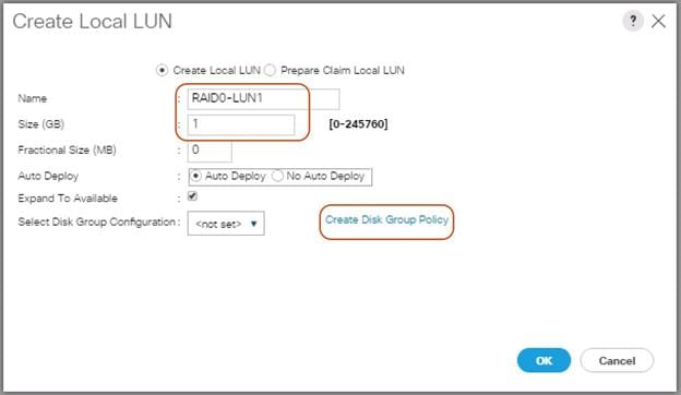
9. Click “Create Disk Group Policy” to Create RAID0 LUN.
10. Type in RAID0-Disk1 in the Name field.
11. (Optional) Enter a description in the Description field.
12. RAID Level = RAID 0 Striped.
13. Select Disk Group Configuration (Manual).
14. Click Add.
15. Type in 1 for Slot Number.
16. Click OK.
17. Under “Change Virtual Drive Configuration:”
a. Modify Access Policy as “Read Write” and Read Policy as “Read Ahead”.
b. Modify Write Cache Policy as “Write Back Good BBU” and IO Policy as “Direct.”
c. Click OK and then OK.
Figure 45 Create Disk Group Policy
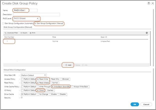
18. Select your previously created Disk Group Policy for the Boot SSDs with the radio button under Select Disk Group Configuration.
19. Select Disk Group Configuration.
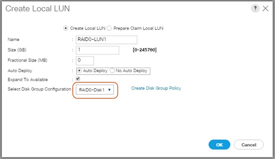
20. Click OK and then OK and click OK..
21. Create the RAID0 LUNs for remaining top loading HDDs by following all the steps.
![]() Note: Make sure to choose “Storage-TopNode” Storage Profile for creating RAID0 LUNs for HDDs installed from Slot 1-26. Then choose “Storage-BottomNode” Storage Profile for creating RAID0 LUNs for HDDs installed from Slot 29-54.
Note: Make sure to choose “Storage-TopNode” Storage Profile for creating RAID0 LUNs for HDDs installed from Slot 1-26. Then choose “Storage-BottomNode” Storage Profile for creating RAID0 LUNs for HDDs installed from Slot 29-54.
Create Service Profile for Cisco UCS C220 M4S Server for Scality Supervisor Node
To create a Service Profile, complete the following steps:
1. Select Servers in the left pane of the Cisco UCS Manager GUI.
2. Go to Servers > Service Profile > root and right-click to choose “Create Service Profile (expert).”
Identify Service Profile
1. Type in Supervisor-Node in the Name field.
2. In the UUID Assignment section, select the UUID Pool you created in the beginning.
3. (Optional) Enter a description in the Description field.
Figure 46 Identify Service Profile
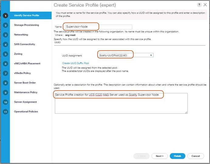
4. Click Next.
Storage Provisioning
1. Go to the Storage Profile Policy tab and select the Storage Profile S3260-TopNode for the top node of the Cisco UCS S3260 Storage Server you created before.
2. Click Next.
Figure 47 Storage Provisioning
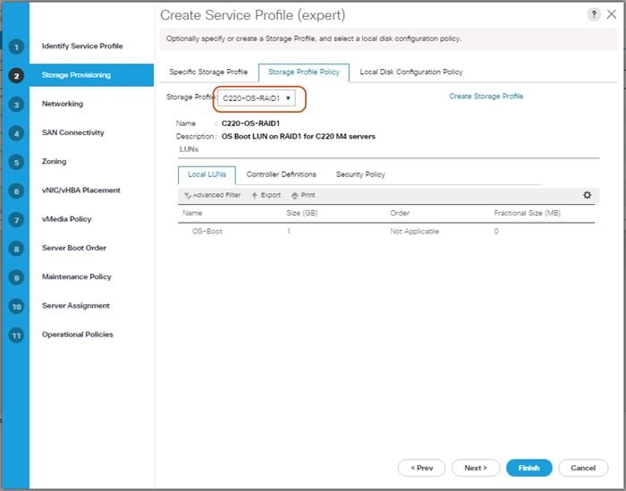
Networking
1. Keep the Dynamic vNIC Connection Policy field at the default.
2. Select LAN connectivity to Use Connectivity Policy created previously.
3. From the LAN Connectivity drop-down list, select “Storage-Node” previously created.
![]() Note: Scality Supervisor Node and Storage-Nodes use the same VNIC interfaces.
Note: Scality Supervisor Node and Storage-Nodes use the same VNIC interfaces.
4. Click Next.
Figure 48 Summary Networking
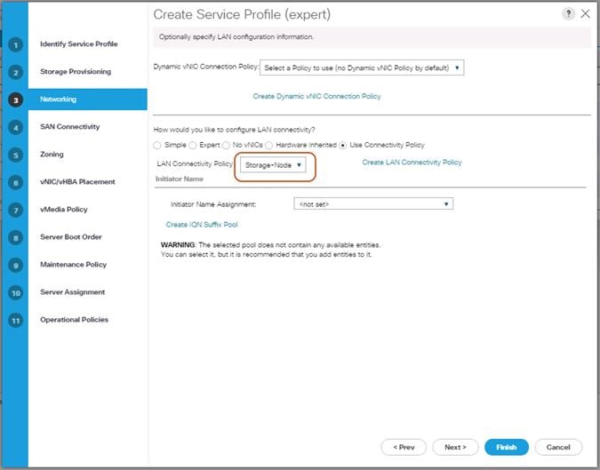
5. Click Next to continue with SAN Connectivity.
6. Select No vHBA for How would you like to configure SAN Connectivity?
7. Click Next to continue with Zoning.
8. Click Next.
vNIC/vHBA Placement
1. Select Let system Perform placement form the drop-down list.
2. Under PCI order section, Sort all the vNICs.
3. Make sure the vNICs order listed as External-Network > 1, then followed by Storage-Mgmt > 2 and Storage-Cluster > 3.
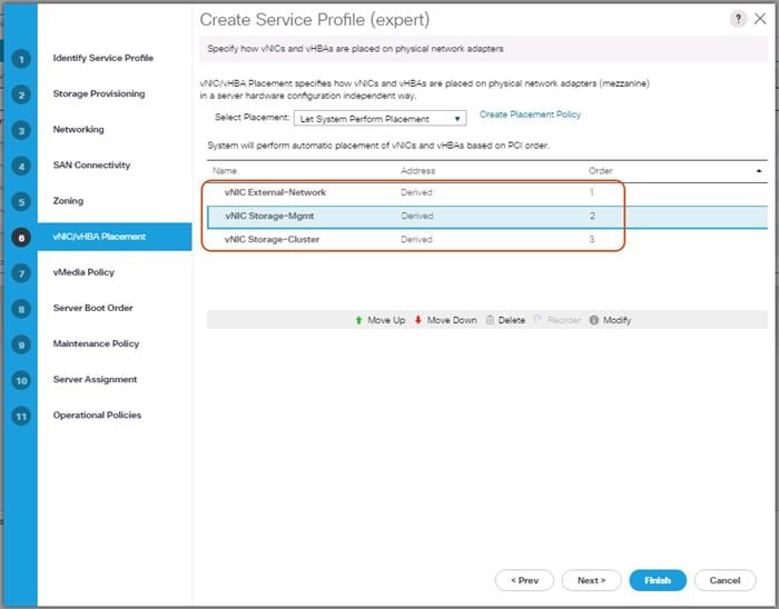
4. Click Next to continue with vMedia Policy.
5. Click Next.
Server Boot Order
1. Select the Boot Policy “Local-OS-Boot” you created before under Boot Policy.
2. Server Boot Order.
3. Click Next.
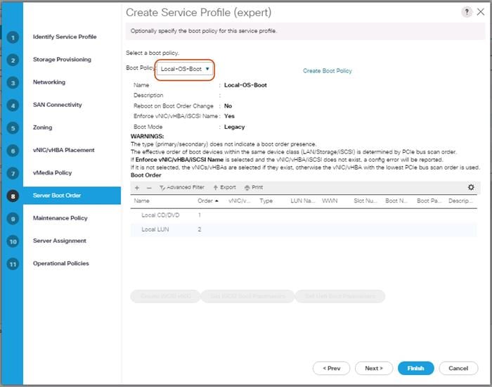
Maintenance Policy
1. Select the Maintenance Policy you created before under Maintenance Policy.
Figure 49 Maintenance Policy
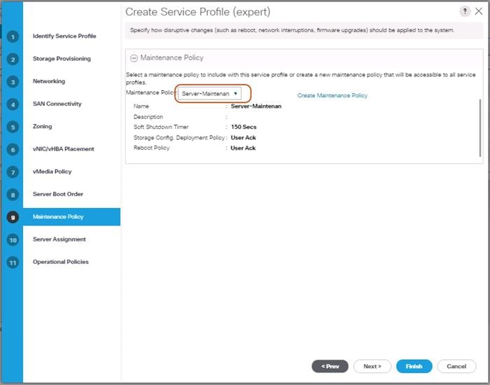
2. Click Next.
3. From the Server Assignment drop-down list, choose “Select existing Server.”
4. Click “Available Servers” radio button.
5. From the Server list, select Rack ID “1” radio button for the C220 M4S Server. This will Associate the service profile.
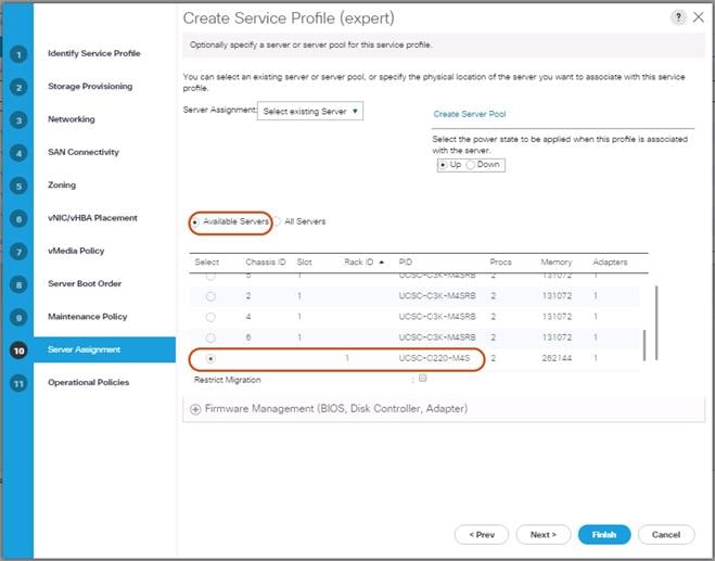
6. Click Next.
Operational Policies
1. Click Finish and then click OK.
2. After Successful creation of “Supervisor-Node” Service profile, the Cisco UCS C220 M4S server will start the Service profile association.
Creating Port Channel for Network Uplinks
Create Port Channel for Fabric Interconnect A/B
To create Port Channels to the connected Nexus 9332PQ switches, complete the following steps:
1. Select the LAN tab in the left pane of the Cisco UCS Manager GUI.
2. Go to LAN > LAN Cloud > Fabric A > Port Channels and right-click Create Port Channel.
3. Type in ID 20.
4. Type in vPC20 in the Name field.
5. Click Next.
6. Select the available ports on the left 27-32 and assign them with >> to Ports in the Port Channel.
7. The “Add Ports” window will prompt you to confirm the selection, click Yes.
Figure 50 Create Port Channel
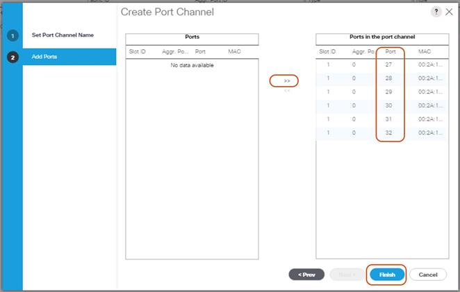
8. Click Finish and then click OK.
9. Repeat these same steps for Fabric B under LAN > LAN Cloud > Fabric B > Port Channels and right-click Create Port Channel.
10. Type in ID 30.
11. Type in VPC30 name in the Name field.
12. Click Next.
13. Select the available ports on the left 27-32 and assign them with >> to Ports in the Port Channel.
14. Click Finish and then click OK.
Configuration of Nexus 9332PQ Switch A and B
Both Cisco UCS Fabric Interconnect A and B are connected to two Cisco Nexus 9332PQ switches for connectivity to Upstream Network. The following sections describe the setup of both Cisco Nexus 9332PQ switches.
Initial Setup of Nexus 9332PQ Switch A and B
To configure Switch A, please connect a Console to the Console port of each switch, power on the switch and complete the following steps:
1. Type yes.
2. Type n.
3. Type n.
4. Type n.
5. Enter the switch name.
6. Type y.
7. Type your IPv4 management address for Switch A.
8. Type your IPv4 management netmask for Switch A.
9. Type y.
10. Type your IPv4 management default gateway address for Switch A.
11. Type n.
12. Type n.
13. Type y for ssh service.
14. Press <Return> and then <Return>.
15. Type y for ntp server.
16. Type the IPv4 address of the NTP server.
17. Press <Return>, then <Return> and again <Return>.
18. Check the configuration and if correct then press <Return> and again <Return>.
The complete setup looks like the following:
---- System Admin Account Setup ----
Do you want to enforce secure password standard (yes/no) [y]: no
Enter the password for "admin":
Confirm the password for "admin":
---- Basic System Configuration Dialog VDC: 1 ----
This setup utility will guide you through the basic configuration of
the system. Setup configures only enough connectivity for management
of the system.
Please register Cisco Nexus9000 Family devices promptly with your
supplier. Failure to register may affect response times for initial
service calls. Nexus9000 devices must be registered to receive
entitled support services.
Press Enter at anytime to skip a dialog. Use ctrl-c at anytime
to skip the remaining dialogs.
Would you like to enter the basic configuration dialog (yes/no): yes
Create another login account (yes/no) [n]:
Configure read-only SNMP community string (yes/no) [n]: no
Configure read-write SNMP community string (yes/no) [n]: no
Enter the switch name : N9k-Fab-A
Continue with Out-of-band (mgmt0) management configuration? (yes/no) [y]: yes
Mgmt0 IPv4 address : 192.168.10.103
Mgmt0 IPv4 netmask : 255.255.255.0
Configure the default gateway? (yes/no) [y]: yes
IPv4 address of the default gateway : 192.168.10.1
Configure advanced IP options? (yes/no) [n]: no
Enable the telnet service? (yes/no) [n]: no
Enable the ssh service? (yes/no) [y]: yes
Type of ssh key you would like to generate (dsa/rsa) [rsa]: rsa
Number of rsa key bits <1024-2048> [1024]: 1024
Configure the ntp server? (yes/no) [n]: yes
NTP server IPv4 address : 192.168.10.2
Configure default interface layer (L3/L2) [L3]: L2
Configure default switchport interface state (shut/noshut) [shut]: shut
Configure CoPP system profile (strict/moderate/lenient/dense) [strict]:
The following configuration will be applied:
password strength-check
switchname N9k-Fab-A
vrf context management
ip route 0.0.0.0/0 192.168.10.1
exit
no feature telnet
ssh key rsa 1024 force
feature ssh
ntp server 192.168.10.2
no system default switchport
system default switchport shutdown
copp profile strict
interface mgmt0
ip address 192.168.10.103 255.255.255.0
no shutdown
Would you like to edit the configuration? (yes/no) [n]: no
Use this configuration and save it? (yes/no) [y]: yes
[########################################] 100%
Copy complete.
User Access Verification
N9k-Fab-A login:
Repeat these steps for the Nexus 9332PQ Switch B with the exception of configuring a different IPv4 management address 192.168.10.104 as described in step 7.
Enable Features on Nexus 9332PQ Switch A and B
To enable the features UDLD, VLAN, HSRP, LACP, VPC, and Jumbo Frames, connect to the management interface via ssh on both switches and complete the following steps on both Switch A and B:
Switch A
N9k-Fab-A# configure terminal
Enter configuration commands, one per line. End with CNTL/Z.
N9k-Fab-A(config)# feature udld
N9k-Fab-A(config)# feature interface-vlan
N9k-Fab-A(config)# feature hsrp
N9k-Fab-A(config)# feature lacp
N9k-Fab-A(config)# feature vpc
N9k-Fab-A(config)# system jumbomtu 9216
N9k-Fab-A(config)# exit
N9k-Fab-A(config)# copy running-config startup-config
Switch B
N9k-Fab-B# configure terminal
Enter configuration commands, one per line. End with CNTL/Z.
N9k-Fab-B(config)# feature udld
N9k-Fab-B(config)# feature interface-vlan
N9k-Fab-B(config)# feature hsrp
N9k-Fab-B(config)# feature lacp
N9k-Fab-B(config)# feature vpc
N9k-Fab-B(config)# system jumbomtu 9216
N9k-Fab-B(config)# exit
N9k-Fab-B(config)# copy running-config startup-config
Configuring VLANs on Nexus 9332PQ Switch A and B
To configure the same VLANs Storage-Management, Storage-Cluster, Client Network, and External Management as previously configured in the Cisco UCS Manager GUI, complete the following steps on Switch A and Switch B:
Switch A
N9k-Fab-A# config terminal
Enter configuration commands, one per line. End with CNTL/Z.
N9k-Fab-A(config)# vlan 10
N9k-Fab-A(config-vlan)# name Storage-Management
N9k-Fab-A(config-vlan)# no shut
N9k-Fab-A(config-vlan)# exit
N9k-Fab-A(config)# vlan 20
N9k-Fab-A(config-vlan)# name Storage-Cluster
N9k-Fab-A(config-vlan)# no shut
N9k-Fab-A(config-vlan)# exit
N9k-Fab-A(config)# vlan 79
N9k-Fab-A(config-vlan)# name External-Mgmt
N9k-Fab-A(config-vlan)# no shut
N9k-Fab-A(config-vlan)# exit
N9k-Fab-A(config)# interface vlan10
N9k-Fab-A(config-if)# description Storage-Mgmt
N9k-Fab-A(config-if)# no shutdown
N9k-Fab-A(config-if)# no ip redirects
N9k-Fab-A(config-if)# ip address 192.168.10.253/24
N9k-Fab-A(config-if)# no ipv6 redirects
N9k-Fab-A(config-if)# hsrp version 2
N9k-Fab-A(config-if)# hsrp 10
N9k-Fab-A(config-if-hsrp)# preempt
N9k-Fab-A(config-if-hsrp)# priority 10
N9k-Fab-A(config-if-hsrp)# ip 192.168.10.1
N9k-Fab-A(config-if-hsrp)# exit
N9k-Fab-A(config-if)# exit
N9k-Fab-A(config)# interface vlan20
N9k-Fab-A(config-if)# description Storage-Cluster
N9k-Fab-A(config-if)# no shutdown
N9k-Fab-A(config-if)# no ip redirects
N9k-Fab-A(config-if)# ip address 192.168.20.253/24
N9k-Fab-A(config-if)# no ipv6 redirects
N9k-Fab-A(config-if)# hsrp version 2
N9k-Fab-A(config-if)# hsrp 20
N9k-Fab-A(config-if-hsrp)# preempt
N9k-Fab-A(config-if-hsrp)# priority 10
N9k-Fab-A(config-if-hsrp)# ip 192.168.20.1
N9k-Fab-A(config-if-hsrp)# exit
N9k-Fab-A(config-if)# exit
Switch B
N9k-Fab-B# config terminal
Enter configuration commands, one per line. End with CNTL/Z.
N9k-Fab-B(config)# vlan 10
N9k-Fab-B(config-vlan)# name Storage-Management
N9k-Fab-B(config-vlan)# no shut
N9k-Fab-B(config-vlan)# exit
N9k-Fab-B(config)# vlan 20
N9k-Fab-B(config-vlan)# name Storage-Cluster
N9k-Fab-B(config-vlan)# no shut
N9k-Fab-B(config-vlan)# exit
N9k-Fab-B(config)# vlan 79
N9k-Fab-B(config-vlan)# name External-Mgmt
N9k-Fab-B(config-vlan)# no shut
N9k-Fab-B(config-vlan)# exit
N9k-Fab-B(config)# interface vlan10
N9k-Fab-B(config-if)# description Storage-Mgmt
N9k-Fab-B(config-if)# no ip redirects
N9k-Fab-B(config-if)# ip address 192.168.10.254/24
N9k-Fab-B(config-if)# no ipv6 redirects
N9k-Fab-B(config-if)# hsrp version 2
N9k-Fab-B(config-if)# hsrp 10
N9k-Fab-B(config-if-hsrp)# preempt
N9k-Fab-B(config-if-hsrp)# priority 5
N9k-Fab-B(config-if-hsrp)# ip 192.168.10.1
N9k-Fab-B(config-if-hsrp)# exit
N9k-Fab-B(config-if)# exit
N9k-Fab-B(config)# interface vlan20
N9k-Fab-B(config-if)# description Storage-Cluster
N9k-Fab-B(config-if)# no ip redirects
N9k-Fab-B(config-if)# ip address 192.168.20.254/24
N9k-Fab-B(config-if)# no ipv6 redirects
N9k-Fab-B(config-if)# hsrp version 2
N9k-Fab-B(config-if)# hsrp 20
N9k-Fab-B(config-if-hsrp)# preempt
N9k-Fab-B(config-if-hsrp)# priority 5
N9k-Fab-B(config-if-hsrp)# ip 192.168.20.1
N9k-Fab-B(config-if-hsrp)# exit
N9k-Fab-B(config-if)# exit
N9k-Fab-B(config)# copy running-config startup-config
Configure vPC and Port Channels on Nexus C9332PQ Switch A and B
To enable vPC and Port Channels on both Switch A and B, complete the following steps:
vPC and Port Channels for Peerlink on Switch A
N9k-Fab-B# config terminal
Enter configuration commands, one per line. End with CNTL/Z.
N9k-Fab-A(config)# vpc domain 2
N9k-Fab-A(config-vpc-domain)# peer-keepalive destination 192.168.10.104
Note:
--------:: Management VRF will be used as the default VRF ::--------
N9k-Fab-A(config-vpc-domain)# peer-gateway
N9k-Fab-A(config-vpc-domain)# exit
N9k-Fab-A(config)# interface port-channel 1
N9k-Fab-A(config-if)# description vPC peerlink for N9k-Fab-A and N9k-Fab-B
N9k-Fab-A(config-if)# switchport
N9k-Fab-A(config-if)# switchport mode trunk
N9k-Fab-A(config-if)# spanning-tree port type network
N9k-Fab-A(config-if)# speed 40000
N9k-Fab-A(config-if)# vpc peer-link
Please note that spanning tree port type is changed to "network" port type on vPC peer-link.
This will enable spanning tree Bridge Assurance on vPC peer-link provided the STP Bridge Assurance
(which is enabled by default) is not disabled.
N9k-Fab-A(config-if)# exit
N9k-Fab-A(config)# interface ethernet 1/1
N9k-Fab-A(config-if)# description connected to peer N9k-Fab-B port 1
N9k-Fab-A(config-if)# switchport
N9k-Fab-A(config-if)# switchport mode trunk
N9k-Fab-A(config-if)# speed 40000
N9k-Fab-A(config-if)# channel-group 1 mode active
N9k-Fab-A(config-if)# exit
N9k-Fab-A(config)# interface ethernet 1/2
N9k-Fab-A(config-if)# description connected to peer N9k-Fab-B port 2
N9k-Fab-A(config-if)# switchport
N9k-Fab-A(config-if)# switchport mode trunk
N9k-Fab-A(config-if)# speed 40000
N9k-Fab-A(config-if)# channel-group 1 mode active
N9k-Fab-A(config-if)# exit
N9k-Fab-A(config)# copy running-config startup-config
vPC and Port Channels for Peerlink on Switch B
N9k-Fab-B# config terminal
Enter configuration commands, one per line. End with CNTL/Z.
N9k-Fab-B(config)# vpc domain 2
N9k-Fab-B(config-vpc-domain)# peer-keepalive destination 192.168.10.103
Note:
--------:: Management VRF will be used as the default VRF ::--------
N9k-Fab-B(config-vpc-domain)# peer-gateway
N9k-Fab-B(config-vpc-domain)# exit
N9k-Fab-B(config)# interface port-channel 1
N9k-Fab-B(config-if)# description vPC peerlink for N9k-Fab-A and N9k-Fab-B
N9k-Fab-B(config-if)# switchport
N9k-Fab-B(config-if)# switchport mode trunk
N9k-Fab-B(config-if)# spanning-tree port type network
N9k-Fab-B(config-if)# speed 40000
N9k-Fab-B(config-if)# vpc peer-link
Please note that spanning tree port type is changed to "network" port type on vPC peer-link.
This will enable spanning tree Bridge Assurance on vPC peer-link provided the STP Bridge Assurance
(which is enabled by default) is not disabled.
N9k-Fab-B(config-if)# exit
N9k-Fab-B(config)# interface ethernet 1/1
N9k-Fab-B(config-if)# description connected to peer N9k-Fab-A port 1
N9k-Fab-B(config-if)# switchport
N9k-Fab-B(config-if)# switchport mode trunk
N9k-Fab-B(config-if)# speed 40000
N9k-Fab-B(config-if)# channel-group 1 mode active
N9k-Fab-B(config-if)# exit
N9k-Fab-B(config)# interface ethernet 1/2
N9k-Fab-B(config-if)# description connected to peer N9k-Fab-A port 2
N9k-Fab-B(config-if)# switchport
N9k-Fab-B(config-if)# switchport mode trunk
N9k-Fab-B(config-if)# speed 40000
N9k-Fab-B(config-if)# channel-group 1 mode active
N9k-Fab-B(config-if)# exit
N9k-Fab-B(config)# copy running-config startup-config
vPC and Port Channels for Uplink from UCS Fabric A & B on Nexus Switch A
N9k-Fab-B# config terminal
Enter configuration commands, one per line. End with CNTL/Z.
N9k-Fab-A(config)# interface port-channel 10
N9k-Fab-A(config-if)# description vPC for UCS FI-A ports 27 to 29
N9k-Fab-A(config-if)# vpc 10
N9k-Fab-A(config-if)# switchport
N9k-Fab-A(config-if)# switchport mode trunk
N9k-Fab-A(config-if)# switchport trunk allowed vlan 10,20,79
N9k-Fab-A(config-if)# spanning-tree port type edge trunk
Edge port type (portfast) should only be enabled on ports connected to a single
host. Connecting hubs, concentrators, switches, bridges, etc... to this
interface when edge port type (portfast) is enabled, can cause temporary bridging loops.
Use with CAUTION
N9k-Fab-A(config-if)# mtu 9216
N9k-Fab-A(config-if)# exit
N9k-Fab-A(config)# interface port-channel 11
N9k-Fab-A(config-if)# description vPC for UCS FI-B ports 27 to 29
N9k-Fab-A(config-if)# vpc 11
N9k-Fab-A(config-if)# switchport
N9k-Fab-A(config-if)# switchport mode trunk
N9k-Fab-A(config-if)# switchport trunk allowed vlan 10,20,79
N9k-Fab-A(config-if)# spanning-tree port type edge trunk
Edge port type (portfast) should only be enabled on ports connected to a single
host. Connecting hubs, concentrators, switches, bridges, etc... to this
interface when edge port type (portfast) is enabled, can cause temporary bridging loops.
Use with CAUTION
N9k-Fab-A(config-if)# mtu 9216
N9k-Fab-A(config-if)# exit
N9k-Fab-A(config)# interface ethernet 1/27-29
N9k-Fab-A(config-if-range)# switchport
N9k-Fab-A(config-if-range)# switchport mode trunk
N9k-Fab-A(config-if-range)# description Uplink from UCS FI-A ports 27 to 29
N9k-Fab-A(config-if-range)# channel-group 10 mode active
N9k-Fab-A(config-if)# exit
N9k-Fab-A(config)# interface ethernet 1/30-32
N9k-Fab-A(config-if-range)# switchport
N9k-Fab-A(config-if-range)# switchport mode trunk
N9k-Fab-A(config-if-range)# description Uplink from UCS FI-B ports 27 to 29
N9k-Fab-A(config-if-range)# channel-group 11 mode active
N9k-Fab-A(config-if)# exit
N9k-Fab-A(config)# copy running-config startup-config
vPC and Port Channels for Uplink from Fabric A and B on Nexus Switch B
N9k-Fab-B# config terminal
Enter configuration commands, one per line. End with CNTL/Z.
N9k-Fab-B(config)# interface port-channel 10
N9k-Fab-B(config-if)# description vPC for UCS FI-A ports 30 to 32
N9k-Fab-B(config-if)# switchport
N9k-Fab-B(config-if)# switchport mode trunk
N9k-Fab-B(config-if)# switchport trunk allowed vlan 10,20,79
N9k-Fab-B(config-if)# spanning-tree port type edge trunk
Edge port type (portfast) should only be enabled on ports connected to a single
host. Connecting hubs, concentrators, switches, bridges, etc... to this
interface when edge port type (portfast) is enabled, can cause temporary bridging loops.
Use with CAUTION
N9k-Fab-B(config-if)# vpc 10
N9k-Fab-B(config-if)# mtu 9216
N9k-Fab-B(config-if)# exit
N9k-Fab-B(config)# interface port-channel 11
N9k-Fab-B(config-if)# description vPC for UCS FI-B ports 30 to 32
N9k-Fab-B(config-if)# switchport
N9k-Fab-B(config-if)# switchport mode trunk
N9k-Fab-B(config-if)# switchport trunk allowed vlan 10,20,79
N9k-Fab-B(config-if)# spanning-tree port type edge trunk
Edge port type (portfast) should only be enabled on ports connected to a single
host. Connecting hubs, concentrators, switches, bridges, etc... to this
interface when edge port type (portfast) is enabled, can cause temporary bridging loops.
Use with CAUTION
N9k-Fab-B(config-if)# vpc 11
N9k-Fab-B(config-if)# mtu 9216
N9k-Fab-B(config-if)# exit
N9k-Fab-B(config)# interface ethernet 1/27-29
N9k-Fab-B(config-if-range)# switchport
N9k-Fab-B(config-if-range)# switchport mode trunk
N9k-Fab-B(config-if-range)# description Uplink from UCS FI-A ports 30 to 32
N9k-Fab-B(config-if-range)# channel-group 10 mode active
N9k-Fab-B(config-if)# exit
N9k-Fab-B(config)# interface ethernet 1/30-32
N9k-Fab-B(config-if-range)# switchport
N9k-Fab-B(config-if-range)# switchport mode trunk
N9k-Fab-B(config-if-range)# description Uplink from UCS FI-B ports 30 to 32
N9k-Fab-B(config-if-range)# channel-group 11 mode active
N9k-Fab-B(config-if)# exit
N9k-Fab-B(config)# copy running-config startup-config
Verification Check of Nexus C9332PQ Configuration for Switch A and B
Switch A
N9k-Fab-B# config terminal
Enter configuration commands, one per line. End with CNTL/Z.
N9k-Fab-A(config)# show vpc brief
Legend:
(*) - local vPC is down, forwarding via vPC peer-link
vPC domain id : 2
Peer status : peer adjacency formed ok
vPC keep-alive status : peer is alive
Configuration consistency status : success
Per-vlan consistency status : success
Type-2 consistency status : success
vPC role : secondary
Number of vPCs configured : 4
Peer Gateway : Enabled
Dual-active excluded VLANs : -
Graceful Consistency Check : Enabled
Auto-recovery status : Disabled
Delay-restore status : Timer is off.(timeout = 30s)
Delay-restore SVI status : Timer is off.(timeout = 10s)
vPC Peer-link status
---------------------------------------------------------------------
id Port Status Active vlans
-- ---- ------ --------------------------------------------------
1 Po1 up 1,10,20,79
vPC status
----------------------------------------------------------------------
id Port Status Consistency Reason Active vlans
-- ---- ------ ----------- ------ ------------
10 Po10 up success success 10,20,79
11 Po11 up success success 10,20,79
N9k-Fab-A(config)#
N9k-Fab-A(config)# show port-channel summary
Flags: D - Down P - Up in port-channel (members)
I - Individual H - Hot-standby (LACP only)
s - Suspended r - Module-removed
S - Switched R - Routed
U - Up (port-channel)
p - Up in delay-lacp mode (member)
M - Not in use. Min-links not met
--------------------------------------------------------------------------------
Group Port- Type Protocol Member Ports
Channel
--------------------------------------------------------------------------------
1 Po1(SU) Eth LACP Eth1/1(P) Eth1/2(P)
10 Po10(SU) Eth LACP Eth1/27(P) Eth1/28(P) Eth1/29(P)
11 Po11(SU) Eth LACP Eth1/30(P) Eth1/31(P) Eth1/32(P)
N9k-Fab-A(config)#
Switch B
N9k-Fab-B# config terminal
Enter configuration commands, one per line. End with CNTL/Z.
N9k-Fab-B(config)# show vpc brief
Legend:
(*) - local vPC is down, forwarding via vPC peer-link
vPC domain id : 2
Peer status : peer adjacency formed ok
vPC keep-alive status : peer is alive
Configuration consistency status : success
Per-vlan consistency status : success
Type-2 consistency status : success
vPC role : primary
Number of vPCs configured : 4
Peer Gateway : Enabled
Dual-active excluded VLANs : -
Graceful Consistency Check : Enabled
Auto-recovery status : Disabled
Delay-restore status : Timer is off.(timeout = 30s)
Delay-restore SVI status : Timer is off.(timeout = 10s)
vPC Peer-link status
---------------------------------------------------------------------
id Port Status Active vlans
-- ---- ------ --------------------------------------------------
1 Po1 up 1,10,20,79
vPC status
----------------------------------------------------------------------
id Port Status Consistency Reason Active vlans
-- ---- ------ ----------- ------ ------------
10 Po10 up success success 10,20,79
11 Po11 up success success 10,20,79
N9k-Fab-B(config)#
N9k-Fab-B(config)# show port-channel summary
Flags: D - Down P - Up in port-channel (members)
I - Individual H - Hot-standby (LACP only)
s - Suspended r - Module-removed
S - Switched R - Routed
U - Up (port-channel)
p - Up in delay-lacp mode (member)
M - Not in use. Min-links not met
--------------------------------------------------------------------------------
Group Port- Type Protocol Member Ports
Channel
--------------------------------------------------------------------------------
1 Po1(SU) Eth LACP Eth1/1(P) Eth1/2(P)
10 Po10(SU) Eth LACP Eth1/27(P) Eth1/28(P) Eth1/29(P)
11 Po11(SU) Eth LACP Eth1/30(P) Eth1/31(P) Eth1/32(P)
N9k-Fab-B(config)#
The formal setup of the Cisco UCS Manager environment and both Cisco Nexus 9332PQ switches is finished and next is the installation of the Red Hat Enterprise Linux 7.4 Operating System.
Installation of Red Hat Enterprise Linux 7.4 Operating System
This section provides the detailed procedures for installing Red Hat Enterprise Linux 7.4 on Cisco UCS C220 M4S and Cisco UCS S3260 Storage Server. The installation uses the KVM console and virtual Media from Cisco UCS Manager.
![]() Note: This requires RHEL 7.4 DVD/ISO media for the installation.
Note: This requires RHEL 7.4 DVD/ISO media for the installation.
Installation of RHEL 7.4 on Cisco UCS C220 M4S and Cisco UCS S3260 M4 Server
To install Red Hat Linux 7.4 operating system on Cisco UCS C220 M4S, complete the following steps:
1. Log in to the Cisco UCS Manager and select the Equipment tab from the left pane.
2. Go to Equipment > Rack-Mounts > Server > Server 1 (Supervisor) and right-click KVM Console.
3. Launch KVM Console.
4. Click the Activate Virtual Devices in the Virtual Media tab.
5. In the UCS KVM window, select the Virtual Media tab and then click CD/DVD.
6. Click Choose File and Browse to the Red Hat Enterprise Linux 7.4 installation ISO image and select then click “Map Drive.”
Figure 51 Red Hat Enterprise Linux 7.4 ISO image
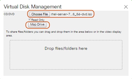
7. In the KVM window, select the Macros > Static Macros > Ctrl-Alt-Del button in the upper left corner.
8. Click OK and then click OK to reboot the system.
9. In the boot screen with the Cisco Logo, press F6 for the boot menu.
10. When the Boot Menu appears, select “Cisco vKVM-Mapped vDVD1.22”
Figure 52 Boot Menu Selection
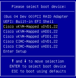
11. When the Red Hat Enterprise Linux 7.4 installer appears, press the Tab button for further configuration options.
12. At the prompt type:
inst.ks=ftp://192.168.10.2/Supervisor.cfg net.ifnames=0 biosdevname=0 ip=192.168.10.160::192.168.10.1:255.255.255.0:Supervisor:eth1:none
![]() Note: We prepared a Linux Kickstart file with all necessary options for an automatic install. The Kickstart file is located on a server in the same subnet.
Note: We prepared a Linux Kickstart file with all necessary options for an automatic install. The Kickstart file is located on a server in the same subnet.
![]() Note: The Kickstart file for the Cisco UCS C220 M4S server for Supervisor Node is in Appendix A. This Kickstart file for the Cisco UCS S3260 M4 Server for Storage Noes is in Appendix B.
Note: The Kickstart file for the Cisco UCS C220 M4S server for Supervisor Node is in Appendix A. This Kickstart file for the Cisco UCS S3260 M4 Server for Storage Noes is in Appendix B.
13. Repeat these steps to install RHEL7.4 on all the UCS S3260 M4 storage servers.
Preparation of all Nodes for Scality RING Installation
Before installing Scality RING, make sure you prepare all nodes with certain configurations.
A summary of the prerequisites for the entire installation with the appropriate changes to the current environment is listed below.
Step 1 - Configuring Network Time Protocol
In our Kickstart installation file, a time server is included. To enable Network Time Protocol on all servers and configure them to use the same source, complete the following steps:
1. Install NTP on all servers:
# yum –y install ntp
# for i in {1..12}; do ssh storage-node{i} ‘yum –y install ntp’; done
2. Configure /etc/ntp.conf on Supervisor node only with the following contents:
# vi /etc/ntp.conf
driftfile /var/lib/ntp/drift
restrict 127.0.0.1
restrict -6 ::1
server 192.168.10.2
fudge 192.168.10.2 stratum 10
includefile /etc/ntp/crypto/pw
keys /etc/ntp/keys
3. Start the ntpd daemon on Supervisor Node:
# systemctl enable ntpd
# systemctl start ntpd
# systemctl status ntpd
4. Copy ntp.conf from Supervisor node to all the Storage nodes:
# cd /etc/
# for i in {1..12}; do ssh storage-node{i} ‘scp supervisor:/etc/ntp.conf /etc/’; done
5. Restart the ntpd daemon on all the storage nodes:
# for i in {1..12}; do ssh storage-node{i} ‘systemctl enable ntpd; done
# for i in {1..12}; do ssh storage-node{i} ‘systemctl start ntpd; done
# for i in {1..12}; do ssh storage-node{i} ‘systemctl status ntpd; done
This sections details how to install Scality RING.
To install Scality RING, complete the following steps:
1. Prepare the Environment:
Download the Scality S3 offline installer from packages.scality.com. For getting access to the above website, please contact your Scality representative. Scality 7.4.0.2 was downloaded for this CVD.
[root@supervisor ~]# sh < scality-ring-run file > –-description-file=CiscoSizing.csv.
![]() Note: For details on the sizing file, please contact Scality.
Note: For details on the sizing file, please contact Scality.
Extracting archive content to /srv/scality
Run /srv/scality/bin/launcher --description-file /root/CiscoSizing.csv
From the Scality Installer Menu, select option1, “Prepare the environment” and press Enter.
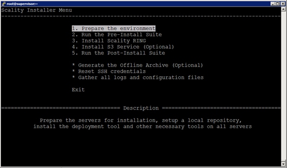
2. Select the SSH authentication method to connect to the Scality Cluster servers:
a. Choose Option 2, “Private Key without passphrase” and press Enter.
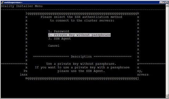
b. The next two screens from installer will prompt for password and the SSH key; leave blank and use the default for the “root” password and use the default one for “/root/.ssh/id_rsa” SSH key and press enter.
c. For admin users, the Scality Supervisor UI requires a password. Choose option1, to “Enter a password”. A prompt will appear, enter a password and confirm it.
d. Run Pre-Install Suite; from the Scality Installer Menu, select option2, “Run the Pre-Install Suite” and press Enter.
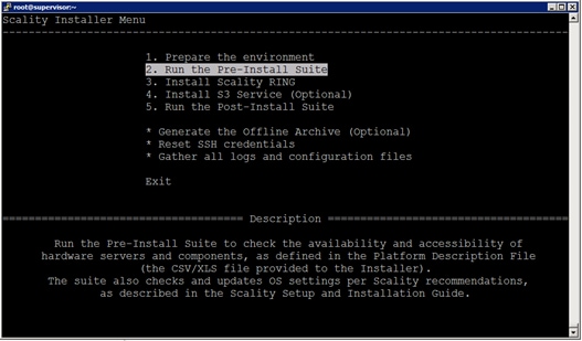
Loading the platform description file '/root/CiscoSizing.csv'... OK
Using private key '/root/.ssh/id_rsa'.
Extracting platform description data... OK
Generating the salt roster file... OK
Preparing and testing SSH connection on every machine... OK
Performing server OS version correspondence check... OK
Generating the pillars for the install... OK
Installing scality-setup-httpd on '192.168.10.150'... OK
Setting up the new repository definitions on every machine... OK
Configuring logging on '192.168.10.150'... OK
Configuring Scality SSH on every machine... OK
Installing sreport on every machine... OK
Installing salt-master on 'supervisor'... OK
Installing salt-minion on every machine... OK
Accepting minion key(s) on the master instance... OK
Syncing configuration on every machine... OK
Installing and configuring scaldisk on every machine... OK
Preparing disks for installation... OK
Restoring repositories on every machine... OK
-- Bootstrap step successful, duration: 0:02:38.990523 --
[2018-06-06 15:29:50-07:00] The bootstrap step finished successfully
Press [Enter] to return to the menu or [Ctrl]+c to exit the installer
![]() Note: Critical errors prompted by the pre-install suite, should preferably be addressed before proceeding to the RING Install.
Note: Critical errors prompted by the pre-install suite, should preferably be addressed before proceeding to the RING Install.
3. Install Scality RING:
a. From the Scality Installer Menu, select option3, “Install Scality RING” and press Enter.
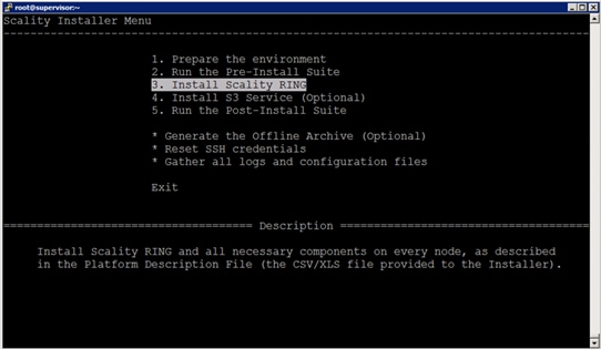
[2018-06-06 15:43:38,288] INFO - Launching install, this might take some time
[2018-06-06 15:43:38-07:00] <roles> Clear the cache and sync modules, grains and pillar ... OK
[2018-06-06 15:43:44-07:00] <roles> Ensure grains is deleted everywhere ... OK
[2018-06-06 15:43:47-07:00] <roles> Check storage nodes minions matcher ... OK
[2018-06-06 15:43:47-07:00] <roles> Setup the group for storage nodes ... OK
[2018-06-06 15:43:48-07:00] <roles> Setup supervisor role ... OK
[2018-06-06 15:43:49-07:00] <roles> Setup storage nodes role ... OK
[2018-06-06 15:43:51-07:00] <roles> Setup Elastic Search cluster role ... OK
[2018-06-06 15:43:54-07:00] <roles> Advertise elasticsearch cluster ... OK
[2018-06-06 15:43:56-07:00] <roles> Setup the group for S3 connectors ... OK
[2018-06-06 15:43:57-07:00] <roles> Setup S3 role ... OK
[2018-06-06 15:44:03-07:00] <roles> Setup the group for NFS connectors ... OK
[2018-06-06 15:44:04-07:00] <roles> Setup NFS role ... OK
[2018-06-06 15:44:07-07:00] <setup> Start scality-setup-httpd ... OK
[2018-06-06 15:44:12-07:00] <setup> Install python-scality ... OK
[2018-06-06 15:44:20-07:00] <setup> Install python-scaldisk ... OK
[2018-06-06 15:44:26-07:00] <setup> Install sreport ... OK
[2018-06-06 15:44:34-07:00] <setup> Detect the disks ... OK
[2018-06-06 15:44:35-07:00] <setup> Publish disks infos ... OK
[2018-06-06 15:44:37-07:00] <sup> Install and configure supervisor ... OK
[2018-06-06 15:46:57-07:00] <sup> Install ringsh ... OK
[2018-06-06 15:47:07-07:00] <rings> Spread rings membership ... OK
[2018-06-06 15:47:10-07:00] <rings> Configure the rings on the supervisor ... OK
[2018-06-06 15:47:47-07:00] <elastic> Install and configure cluster elasticsearch ... OK
[2018-06-06 15:48:12-07:00] <supapi> Configure the supapi service ... OK
[2018-06-06 15:48:24-07:00] <supapi> Install the cloud monitoring service ... OK
[2018-06-06 15:49:41-07:00] <disks> Partition and format disks ... OK
[2018-06-06 15:59:14-07:00] <disks> Mount all disks ... OK
[2018-06-06 16:50:31-07:00] <nodes> Install and configure storage nodes ... OK
[2018-06-06 16:52:50-07:00] <keyspace> Compute the keyspace ... OK
[2018-06-06 16:53:07-07:00] <keyspace> Spread the keyspace to storage nodes ... OK
[2018-06-06 16:53:12-07:00] <keyspace> Make storage nodes join rings ... OK
[2018-06-06 16:53:22-07:00] <conns> Install NFS connectors ... OK
[2018-06-06 16:54:10-07:00] <conns> Install S3 connectors ... OK
[2018-06-06 16:54:44-07:00] <post> Install external tools ... OK
[2018-06-06 16:54:57-07:00] <exit> Removing the credentials ... OK
[2018-06-06 16:54:59-07:00] <exit> Restoring repositories definitions
Press [Enter] to return to the menu or [Ctrl]+c to exit the installer
4. Installing S3 Service Connectors:
a. From the Scality Installer Menu, select option4, “Install S3 Service(optional)” and press Enter.
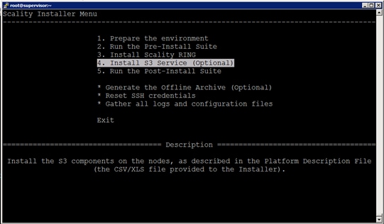
[2018-06-06 17:24:49-07:00] Searching s3 offline archive file ... OK
[2018-06-06 17:24:49-07:00] Extracting s3 offline archive ... OK
s3 installation's detail is found in /srv/scality/s3/s3-offline/federation/ansible.log
[2018-06-06 17:29:51-07:00] Creating s3 playbook from description file ... OK
[2018-06-06 17:29:56-07:00] Generating vault environment configuration ... OK
[2018-06-06 17:30:03-07:00] Running s3 ansible playbook to install the s3 connector ... OK
[2018-06-06 17:41:08-07:00] Setup identisee credentials ... OK
s3 connector successfully installed
[2018-06-06 17:41:11-07:00] The s3 step finished successfully
Press [Enter] to return to the menu or [Ctrl]+c to exit the installer
5. Run the Post-Installer Suite:
a. From the Scality Installer Menu, select option5, “Run the Post-Installer” and press Enter.
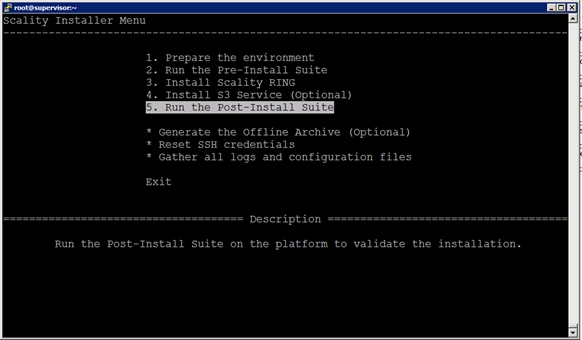
Script installation detail is found in /var/log/postinstall_launcher.log
[2018-06-07 15:30:49-07:00] Setting up the new repositories definitions on every machine ... OK
[2018-06-07 15:30:56-07:00] Installing the postinstallchecks ... OK
Running the postinstallchecks
Running script using salt
Starting checks on supervisor,storage-node11,storage-node10,storage-node12,storage-node9,storage-node8,storage-node5,storage-node4,storage-node7,storage-node6,storage-node1,storage-node3,storage-node2
Checking if server is handled by salt
Checking missing pillars
Gathering info from servers (salt mine.send) for consistency check later
Running tests
The result is found in: /root/post-install-checks-results.tgz
[2018-06-07 15:36:04-07:00] The postinstall step finished successfully
Press [Enter] to return to the menu or [Ctrl]+c to exit the installer
Validate Scality RING and S3 Installation
1. Launch Supervisor UI “http://192.168.10.164/sup/local” and logon as “admin” user.
2. From the UI, click Rings > Dashboard > Topology. Make sure the DATA RING and META RING is operational without any errors.
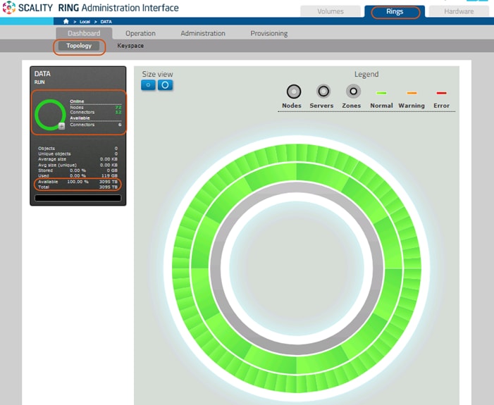
3. Make sure the NFS connectors are installed on 6 Storage nodes.
4. From the UI, click Rings > Operations > Connectors.
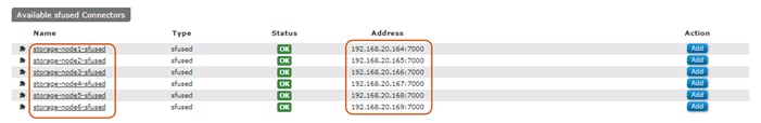
5. Make sure the S3 Connectors are installed on 5 storage nodes as described in the CiscoSizing.csv file:
[root@supervisor ~]# for i in `seq 1 5`; do ssh storage-node$i "docker ps |grep scality-frontend-logger" ; done
e6764842d3ae scality/s3:7.4.0.2 "/scality-bin/logr..." 12 minutes ago Up 12 minutes scality-frontend-logger
ebec58df2d95 scality/s3:7.4.0.2 "/scality-bin/logr..." 12 minutes ago Up 12 minutes scality-frontend-logger
f0c96d538497 scality/s3:7.4.0.2 "/scality-bin/logr..." 12 minutes ago Up 12 minutes scality-frontend-logger
07ebb086a97f scality/s3:7.4.0.2 "/scality-bin/logr..." 12 minutes ago Up 12 minutes scality-frontend-logger
3b48b98f71f8 scality/s3:7.4.0.2 "/scality-bin/logr..." 12 minutes ago Up 12 minutes scality-frontend-logger
[root@supervisor ~]#
![]() Note: In this solution, we have performed the performance testing and Failover testing with 12 S3 connectors. In case you need additional S3 connectors, follow the steps below.
Note: In this solution, we have performed the performance testing and Failover testing with 12 S3 connectors. In case you need additional S3 connectors, follow the steps below.
Installing 7 Additional S3 Connectors
1. Logon to Supervisor node, then Append the ROLE_S3 to all the storage nodes. Run this command:
[root@supervisor ~]# salt -G 'roles:ROLE_STORE' grains.append roles ROLE_S3
storage-node4:
The val ROLE_S3 was already in the list roles
storage-node5:
The val ROLE_S3 was already in the list roles
storage-node1:
The val ROLE_S3 was already in the list roles
storage-node3:
The val ROLE_S3 was already in the list roles
storage-node2:
The val ROLE_S3 was already in the list roles
[root@supervisor ~]#
2. Make a copy of the current env:
cp -r /srv/scality/s3/s3-offline/federation/env/s3config /srv/scality/s3/s3-offline/federation/env/s3config.org
3. Make the necessary edits to the inventory file to defines the stateless connectors:
4. The following are five S3 connectors configured based on the “CiscoSizing.csv” description file.
[root@supervisor]# vi /srv/scality/s3/s3-offline/federation/env/s3config
# Here you can assign IP/hostname to the clusters members
# They should start by md[1-5] or wsb[1-5] and be followed by -clusterX
md1-cluster1 ansible_host=192.168.10.173
md2-cluster1 ansible_host=192.168.10.171
md3-cluster1 ansible_host=192.168.10.174
md4-cluster1 ansible_host=192.168.10.170
md5-cluster1 ansible_host=192.168.10.172
# Here you specify which server will run a S3 connector.
[runners_s3]
# Decoupled deployment
# You can add as many servers as you need
md1-cluster1
md2-cluster1
md3-cluster1
md4-cluster1
md5-cluster1
5. Add remaining 7 S3 connectors on the S3config file.
Below is the inventory file after adding 7 more S3 connectors:
# Here you can assign IP/hostname to the clusters members
# They should start by md[1-5] or wsb[1-5] and be followed by -clusterX
md1-cluster1 ansible_host=192.168.10.173
md2-cluster1 ansible_host=192.168.10.171
md3-cluster1 ansible_host=192.168.10.174
md4-cluster1 ansible_host=192.168.10.170
md5-cluster1 ansible_host=192.168.10.172
conn1-cluster1 ansible_host=192.168.10.164
conn2-cluster1 ansible_host=192.168.10.165
conn3-cluster1 ansible_host=192.168.10.166
conn4-cluster1 ansible_host=192.168.10.167
conn5-cluster1 ansible_host=192.168.10.168
conn6-cluster1 ansible_host=192.168.10.169
conn7-cluster1 ansible_host=192.168.10.175
# Here you specify which server will run a S3 connector.
[runners_s3]
# Decoupled deployment
# You can add as many servers as you need
md1-cluster1
md2-cluster1
md3-cluster1
md4-cluster1
md5-cluster1
conn1-cluster1
conn2-cluster1
conn3-cluster1
conn4-cluster1
conn5-cluster1
conn6-cluster1
conn7-cluster1
6. Rerun federation to install S3 connectors on remaining Nodes:
[root@supervisor]# cd /srv/scality/s3/s3-offline/federation
[root@supervisor federation]# ./ansible-playbook -i env/s3config/inventory run.yml -l conn*
7. To validate additional S3 connectors installed on the Scality RING:
[root@supervisor ~]# for i in `seq 1 12`; do ssh storage-node$i "docker ps |grep scality-frontend-logger" ; done
fd1b475a8bbd scality/s3:7.4.0.2 "/scality-bin/logr..." 14 minutes ago Up 14 minutes scality-frontend-logger
ae4549057f61 scality/s3:7.4.0.2 "/scality-bin/logr..." 14 minutes ago Up 14 minutes scality-frontend-logger
f3cf7b30f01b scality/s3:7.4.0.2 "/scality-bin/logr..." 14 minutes ago Up 14 minutes scality-frontend-logger
0bd56ac633c7 scality/s3:7.4.0.2 "/scality-bin/logr..." 14 minutes ago Up 14 minutes scality-frontend-logger
398a088a93b8 scality/s3:7.4.0.2 "/scality-bin/logr..." 14 minutes ago Up 14 minutes scality-frontend-logger
72144c92852a scality/s3:7.4.0.2 "/scality-bin/logr..." 14 minutes ago Up 14 minutes scality-frontend-logger
e6764842d3ae scality/s3:7.4.0.2 "/scality-bin/logr..." 39 minutes ago Up 39 minutes scality-frontend-logger
ebec58df2d95 scality/s3:7.4.0.2 "/scality-bin/logr..." 39 minutes ago Up 39 minutes scality-frontend-logger
f0c96d538497 scality/s3:7.4.0.2 "/scality-bin/logr..." 39 minutes ago Up 39 minutes scality-frontend-logger
07ebb086a97f scality/s3:7.4.0.2 "/scality-bin/logr..." 39 minutes ago Up 39 minutes scality-frontend-logger
3b48b98f71f8 scality/s3:7.4.0.2 "/scality-bin/logr..." 39 minutes ago Up 39 minutes scality-frontend-logger
1638b53d51e0 scality/s3:7.4.0.2 "/scality-bin/logr..." 14 minutes ago Up 14 minutes scality-frontend-logger
[root@supervisor ~]#
Functional Testing of NFS Connectors
This section details how to create Volumes and configure the NFS exports and perform functional testing of those exports.
1. Click the “Volumes” tab in the supervisor GUI, then click on “NEW VOLUME”:
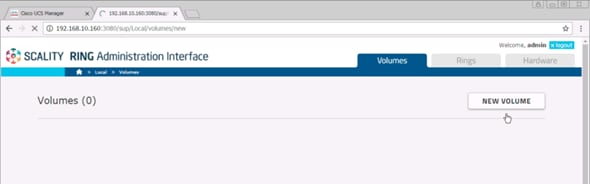
2. Select all available connectors and fill in the appropriate fields:
Name: Test1
Type: SoFS
Device ID: 1
Data RING: DATA
Data RING Replication Policy: ARC 9+3
Metadata RING: META
Metadata RING Replication Policy: COS 4+ (Replication)
a. Click Create.
b. Under Available Connectors select NFS connectors “storage-node1-sfused” and “storage-node2-sfused.”
c. Select Role as “NFS” and click ADD.
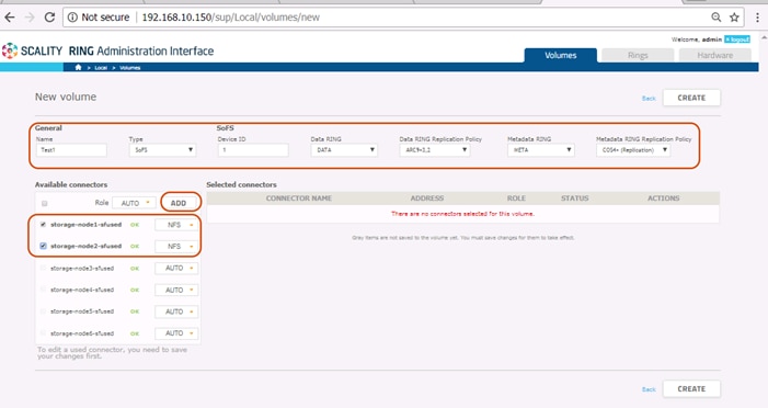
3. Verify that the ROLE of each NFS connector is set to “NFS” and click “Enable.”
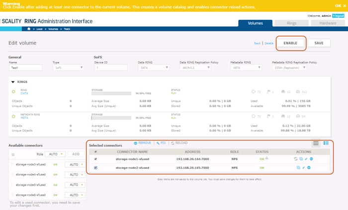
4. To create exports, click “Edit NFS” option from ACTIONS as shown below:
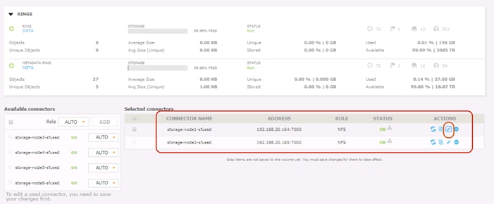
5. Click the Edit action (identified by the symbol of a pencil) for each connector and fill in the export details.
a. Provide the path as “export1” and provide RW credentials under options as shown below.
b. Click Save.
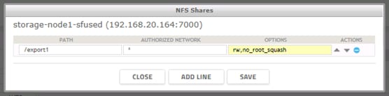
6. Create a NFS export for “storage-node2-sfused” as export2.
7. When the NFS Shares are created, click “SAVE” and then click “Enable.”
8. To test NFS functionality, the supervisor server may be utilized as a NFS client, install nfs-utils on the NFS client:
#yum –y install nfs-utils
9. Mount the export:
# cd /mnt; mkdir export1 export2
# mount 192.168.20.164:/export1 /mnt/export1
# mount 192.168.20.165:/export2 /mnt/export2
![]() Note: 192.168.20.161 is the data NIC of NFS traffic from Storage-node1. 192.168.20.162 is the data NIC of NFS traffic from Storage-node2.
Note: 192.168.20.161 is the data NIC of NFS traffic from Storage-node1. 192.168.20.162 is the data NIC of NFS traffic from Storage-node2.
10. A simple functional test may be performed by copying files to and from the NFS-mounted directories.
Functional Testing of S3 Connectors
This section details how to install and configure s3cmd to perform functional testing of S3 connectors.
To test S3 connectors, the supervisor server may be utilized as a S3 client.
1. Install s3cmd
# yum -y install s3cmd
2. Before creating bucket, Make sure s3cmd has “no output”
# s3cmd ls
(no output)
3. Create bucket to upload and download files via s3cmd.
# s3cmd mb s3://cvdbucket
Bucket 's3://cvdbucket/' created
# s3cmd ls
2018-05-29 23:33 s3://cvdbucket
4. Upload files via s3cmd.
The following example shows how to upload /etc/services, Scality install run file.
# s3cmd put FILE /etc/services s3://cvdbucket/services
upload: '/etc/services' -> 's3://cvdbucket/services' [1 of 1]
670293 of 670293 100% in 0s 3.69 MB/s done
# s3cmd put FILE /root/scality-ring-7.4.run s3://cvdbucket/scalityrunfile
upload: '/root/scality-ring-7.4.run' -> 's3://cvdbucket/scalityrunfile' [part 1 of 21, 15MB] [1 of 1]
15728640 of 15728640 100% in 0s 46.08 MB/s done
upload: '/root/scality-ring-7.4.run' -> 's3://cvdbucket/scalityrunfile' [part 2 of 21, 15MB] [1 of 1]
15728640 of 15728640 100% in 0s 35.92 MB/s done
upload: '/root/scality-ring-7.4.run' -> 's3://cvdbucket/scalityrunfile' [part 3 of 21, 15MB] [1 of 1]
…
…
upload: '/root/scality-ring-7.4.run' -> 's3://cvdbucket/scalityrunfile' [part 19 of 21, 15MB] [1 of 1]
15728640 of 15728640 100% in 0s 51.66 MB/s done
upload: '/root/scality-ring-7.4.run' -> 's3://cvdbucket/scalityrunfile' [part 20 of 21, 15MB] [1 of 1]
15728640 of 15728640 100% in 0s 48.33 MB/s done
upload: '/root/scality-ring-7.4.run' -> 's3://cvdbucket/scalityrunfile' [part 21 of 21, 3MB] [1 of 1]
3181642 of 3181642 100% in 0s 46.82 MB/s done
5. Download files using s3cmd.
The following example shows how to download the files /etc/services, scality install run file.
# s3cmd get s3://cvdbucket/services
download: 's3://cvdbucket/services' -> './services' [1 of 1]
670293 of 670293 100% in 0s 14.67 MB/s done
# s3cmd get s3://cvdbucket/scalityrunfile
download: 's3://cvdbucket/scalityrunfile' -> './scalityrunfile' [1 of 1]
317754442 of 317754442 100% in 1s 248.73 MB/s done
# s3cmd ls s3://cvdbucket
2017-02-10 23:37 317754442 s3://cvdbucket/scalityrunfile
2017-02-10 23:36 670293 s3://cvdbucket/services
![]() Note: This makes sure that the functional testing of S3 connectors are using the s3cmd tool.
Note: This makes sure that the functional testing of S3 connectors are using the s3cmd tool.
Performance evaluation was done on a 12 node cluster. Cosbench was used for load testing the cluster. The tests were conducted on default configurations on Cisco UCS and Scality. The purpose of the tests is to get an idea of the performance of the cluster and should nowhere be considered as benchmark values.
Performance data was collected on 6 chassis 12 node S3260 storage servers with 26 x 10TB HDD disks and 2 x 800 GB SSD’s for metadata on each server. A sufficient number of Clients were added to saturate the cluster. Each server had 40 Gb of Network configured for client traffic. Therefore, in a 12 Node configuration, the max capacity is 480 Gb of Client network. Around 10 Clients each with 40GB network capacity were used as clients on the setup. This is useful when your workload is bandwidth intensive, such as block sizes 1MB and more.
S3 Performance Tests
Cosbench was installed on all the 10 client servers worked as driver nodes for generating the workload.
An example of the configuration file is shown below:
<storage type="s3" timeout="10000" retry="3" config="accesskey=65c231b4c6317cd274c7;secretkey=St/9BK1KsLZJTyktOW6Cw9Am2bTcdI3Iioe8QzGt;endpoint=http://s3.ciscoscality.com" />
<workstage name="prepare_1MB" ilosuredelay="60">
<work type="prepare" workers="100" config="cprefix=bucket-rf3;containers=r(1,1);oprefix=run2-600-1m_; objects=r(1,102400);sizes=c(1)MB" />
</workstage>
Write and Read tests were done on single bucket and 10 buckets and few of the results captured are listed below.
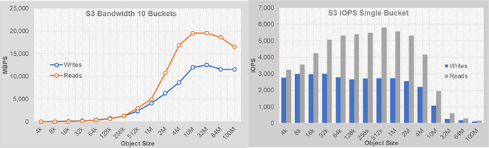
· By using 10 buckets the read bandwidth peaked to almost 19 GB/sec, while writes remained around 12 GB/sec.
· The Write IOPS with single bucket were around 3000 IOPS while read IOPS went up to 6000.
· Multiple buckets increase the write IOPS.
· The peak saturation of bandwidth observed around 10-32 MB object sizes.
· The peak iops were observed around 512k and 1M object sizes.
NFS Performance Tests
One volume was created from each of the 6 connectors and mounted on the clients. Fio tool was used for testing read and writes. The data captured as part of the testing is shown below.
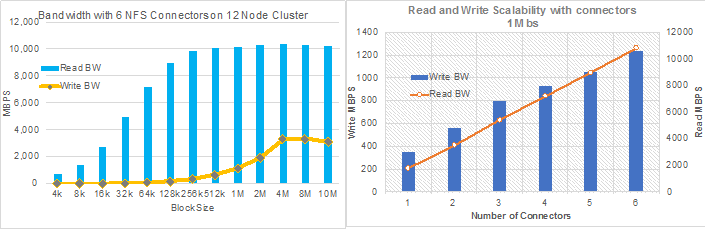
· Around 10,000 MBPS for reads and 3,500 MBPS for writes were observed.
· Tests were performed to access performance by adding the connectors at 1 MB block size. The write and read throughputs increased almost linearly by adding the connectors as shown above.
The high availability of this solution was validated by failing out one of the components of the infrastructure.
The purpose of the HA tests is to ensure Business Continuity when the underlying hardware components fail and study the behavior of the system during fault injections. The following points were considered while doing the HA tests.
· The Cluster will have reasonable amount of load when the fault is injected. The outputs like bandwidth and IOPS from the cluster will be gathered before and after the fault injection and after the restoration of the failed components.
· Only one fault is injected at any point of time. No double failures are considered.
· Performance degradation is acceptable but there should not be any business interruption. The underlying infrastructure components should continue to operate with the remaining components.
A few of the HA tests conducted were:
1. Fabric Interconnect Failures
2. Nexus 9000 Failures
3. S3 Connector, NFS Connectors, and Disk Failures
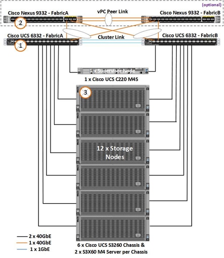
Fabric Interconnect Failures
For checking the business continuity of the system during Fabric Interconnect failures, one of the Fabric interconnects was rebooted after ramping up load through Cosbench. The sequence of events for fault injection and checking the health of the cluster is provided below:
1. Log into one of the Fabric Interconnects.
2. Connect Local Management on A
scality-pod2-A# connect local-mgmt A
……….
scality-pod2-A(local-mgmt)# show cluster extended-state
Cluster Id: 0xba13e47e876d11e7-0x99df002a1029453f
Start time: Sat Nov 11 19:14:33 2017
Last election time: Thu Feb 15 08:51:36 2018
A: UP, PRIMARY
B: UP, SUBORDINATE
A: memb state UP, lead state PRIMARY, mgmt services state: UP
B: memb state UP, lead state SUBORDINATE, mgmt services state: UP
heartbeat state PRIMARY_OK
INTERNAL NETWORK INTERFACES:
eth1, UP
eth2, UP
HA READY
Detailed state of the device selected for HA storage:
Chassis 7, serial: FOX2036G8U6, state: active
Server 2, serial: FCH2033V31P, state: active
Server 4, serial: FCH2034V0UG, state: active
S3 Cosbench test started for 10MB block size and with 480 workers.
The following data was gathered after ramping up the load before fault injection.
CPU utilization % before fault injection:
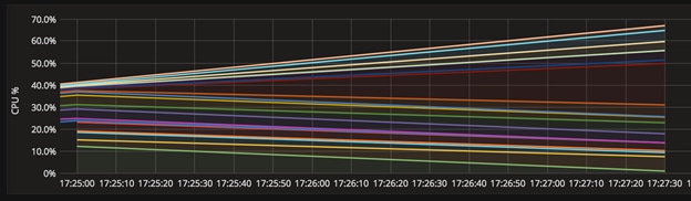
Cosbench graphs:
![]()
Bandwidth around 10.68 GB/s:
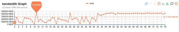
The cluster was doing around 10.68 GB/s at 10MB objects size before fault injection.
Inject fault into the system:
Rebooted the fabric
scality-pod2-A(local-mgmt)#
scality-pod2-A(local-mgmt)# reboot
Before rebooting, please take a configuration backup.
Do you still want to reboot? (yes/no):yes
After the FI reboot:
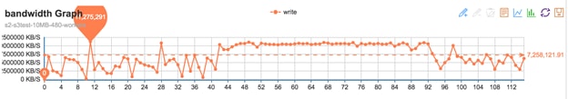
When one of the FI’s is down, cosbench continues to send the requests. However the bandwidth comes down to 7.3 GB/sec from 10.68 GB/sec now.
Ring data dashboard reports cluster as healthy:
The ring dash board does not show any faults because of FI failure.
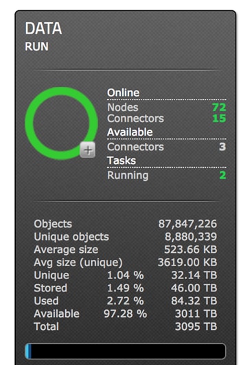
scality-pod2-B# show cluster extended-state
Cluster Id: 0xba13e47e876d11e7-0x99df002a1029453f
Start time: Tue Jan 23 01:34:43 2018
Last election time: Tue Mar 13 00:27:08 2018
B: UP, PRIMARY
A: DOWN, INAPPLICABLE
B: memb state UP, lead state PRIMARY, mgmt services state: UP
A: memb state DOWN, lead state INAPPLICABLE, mgmt services state: DOWN
heartbeat state SECONDARY_FAILED
INTERNAL NETWORK INTERFACES:
eth1, UP
eth2, DOWN
HA NOT READY
Peer Fabric Interconnect is down
Detailed state of the device selected for HA storage:
Chassis 7, serial: FOX2036G8U6, state: active
Server 2, serial: FCH2033V31P, state: active
Server 4, serial: FCH2034V0UG, state: active
HA is not ready but FI’s are up
The above output confirms that FI is down now and the cluster is running on single FI in a degraded mode.
scality-pod2-B# show cluster extended-state
Cluster Id: 0xba13e47e876d11e7-0x99df002a1029453f
Start time: Tue Jan 23 01:34:43 2018
Last election time: Tue Mar 13 00:32:54 2018
B: UP, PRIMARY
A: UP, SUBORDINATE
B: memb state UP, lead state PRIMARY, mgmt services state: UP
A: memb state UP, lead state SUBORDINATE, mgmt services state: UP
heartbeat state PRIMARY_OK
INTERNAL NETWORK INTERFACES:
eth1, UP
eth2, UP
HA DOWNGRADED
HA not ready on peer Fabric Interconnect
Detailed state of the device selected for HA storage:
Chassis 7, serial: FOX2036G8U6, state: active
Server 2, serial: FCH2033V31P, state: active
Server 4, serial: FCH2034V0UG, state: active
The FI has come up. However it is not fully ready yet.
scality-pod2-B# show cluster extended-state
Cluster Id: 0xba13e47e876d11e7-0x99df002a1029453f
Start time: Tue Jan 23 01:34:43 2018
Last election time: Tue Mar 13 00:32:54 2018
B: UP, PRIMARY
A: UP, SUBORDINATE
B: memb state UP, lead state PRIMARY, mgmt services state: UP
A: memb state UP, lead state SUBORDINATE, mgmt services state: UP
heartbeat state PRIMARY_OK
INTERNAL NETWORK INTERFACES:
eth1, UP
eth2, UP
HA READY
Detailed state of the device selected for HA storage:
Chassis 7, serial: FOX2036G8U6, state: active
Server 2, serial: FCH2033V31P, state: active
Server 4, serial: FCH2034V0UG, state: active
At this time, FI joined back and HA is in Ready status.
Bandwidth:
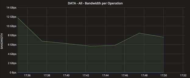
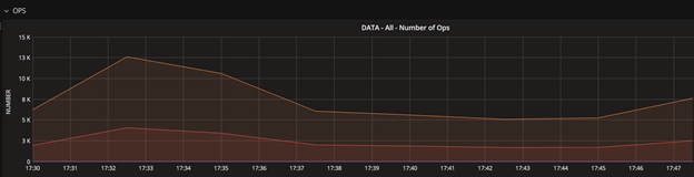
The system recovers after the Fabric joins the cluster and when HA READY. The dip in the graphs show the activity when the FI was rebooted.
Nexus 9000 Switch failures:
Similar to FI failures, one of the upstream Nexus switches was reloaded to make sure that there is business continuity. As both the FI’s are connected to either of the switches and with VPC, the requests from the Nexus will still be forwarded to the FI’s.
Reloaded the switch to check VPC status and impact on the application.
Similar workload as FI failures above was started on the system:
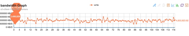
The N9K switch was reloaded.
N9k-Fab-A(config)# show version | grep uptime
Kernel uptime is 163 day(s), 8 hour(s), 18 minute(s), 59 second(s)
N9k-Fab-A(config)#
N9k-Fab-A(config)# reload
This command will reboot the system. (y/n)? [n] y
N9k-Fab-A# show version | grep uptime
Kernel uptime is 0 day(s), 0 hour(s), 4 minute(s), 33 second(s)
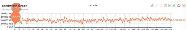
System was doing writes of around 5.7 GB/s when the Nexus switch was reloaded.
System continues to operate without any interruption
N9k-Fab-A# show vpc br
Legend:
(*) - local vPC is down, forwarding via vPC peer-link
vPC domain id : 201
Peer status : peer adjacency formed ok
vPC keep-alive status : peer is alive
Configuration consistency status : success
Per-vlan consistency status : success
Type-2 consistency status : success
……..
vPC status
----------------------------------------------------------------------
id Port Status Consistency Reason Active vlans
-- ---- ------ ----------- ------ ------------
10 Po10 up success success 10,20,79
11 Po11 up success success 10,20,79
S3 Connector Failures
Client load was generated using cosbench and one of the S3 Connectors (which is also the storage node) was shut down from Cisco UCS.
Status of the connectors before fault injection:
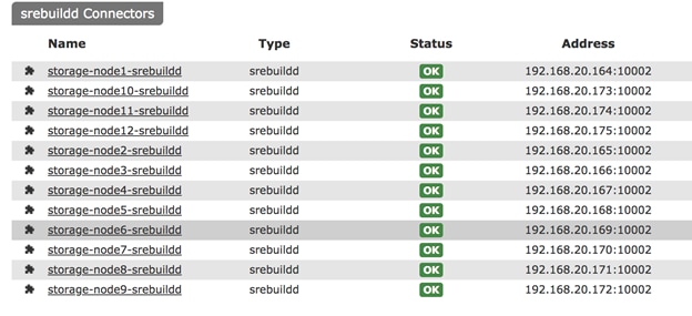
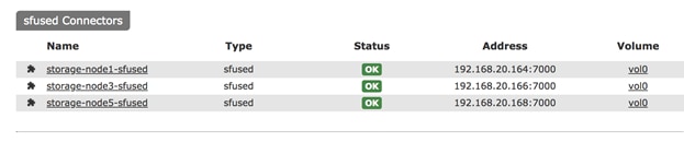
Run Cosbench to put some load on the system on all connectors, then power off node2 and check the status.
Writes were going around 10 GB/s:
![]()
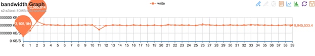
Fault injected by powering off Node 2:
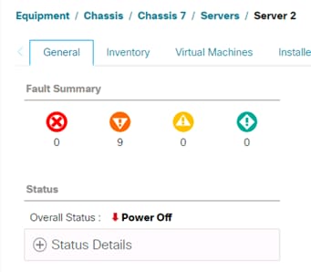
One of the Cosbench clients reports an error as shown below:
2018-03-13 11:25:06,099 [WARN] [S3Storage] - below exception encountered when creating object myobjects34950 at test10mb4: Failed to reset the request input stream; If the request involves an input stream, the maximum stream buffer size can be configured via request.getRequestClientOptions().setReadLimit(int)
Status as observed from Scality Supervisor console
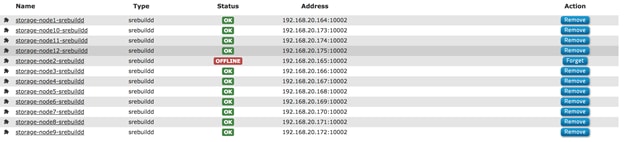
The cosbench bandwidth drops to 9.4 GB/s of writes from 10.48 GB/s as below. It should be noted that we brought down 1 of the 12 x S3 connectors/storage nodes here.
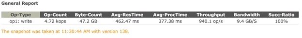
After running for few minutes the server was brought up again.
Server comes up at
[root@storage-node2 ~]# uptime
11:35:26 up 0 min, 1 user, load average: 1.08, 0.26, 0.08
Supervisor shows node the failed node as up now:
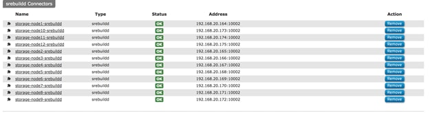
The storage-node2 joins the cluster and starts sharing the load.
[root@supervisor ~]# salt 'stor*' cmd.run "top -b -n3 | head -1"
storage-node12:
top - 11:42:33 up 4 days, 20:28, 0 users, load average: 3.02, 4.18, 4.14
storage-node8:
top - 11:42:33 up 4 days, 20:39, 0 users, load average: 16.90, 17.75, 17.48
storage-node9:
top - 11:42:34 up 4 days, 20:31, 0 users, load average: 8.35, 13.43, 15.49
storage-node10:
top - 11:42:34 up 4 days, 17:38, 0 users, load average: 16.78, 16.70, 16.43
storage-node6:
top - 11:42:34 up 4 days, 20:41, 0 users, load average: 12.57, 18.44, 18.89
storage-node2:
top - 11:42:34 up 7 min, 0 users, load average: 39.43, 37.08, 19.75
storage-node3:
top - 11:42:34 up 4 days, 20:44, 0 users, load average: 47.86, 42.08, 40.14
storage-node4:
top - 11:42:34 up 4 days, 20:44, 0 users, load average: 25.75, 32.88, 34.42
storage-node1:
top - 11:42:34 up 4 days, 20:55, 0 users, load average: 17.78, 18.72, 19.07
storage-node7:
top - 11:42:34 up 4 days, 20:39, 0 users, load average: 14.74, 16.42, 16.31
storage-node5:
top - 11:42:34 up 4 days, 20:41, 0 users, load average: 14.69, 13.93, 14.41
storage-node11:
top - 11:42:34 up 4 days, 20:29, 0 users, load average: 47.80, 42.01, 25.29
Balancing Kicks Off on Nodes after storage-node2 joins the cluster:
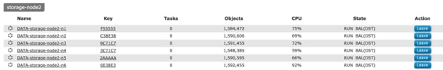
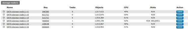
When balancing is on, the following background tasks were observed:
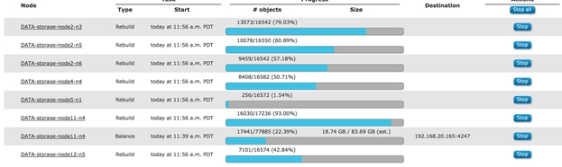
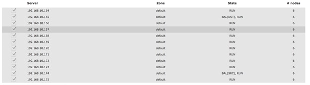
The output drops to 5.5 GB/sec while rebuild is on:
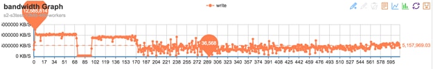
NFS Connector Failures
Similar to S3 connector failures one of the NFS Connectors was powered off while FIO tests were running.
In order to get full high availability for the volumes for Host failures, a minimum of 2 connectors should be attached to each volume as shown below. On the test bed three connectors were chosen for vol0. This provides HA to vol0 on failure of the connectors.
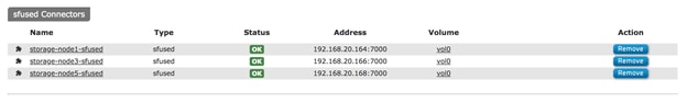
vol0 volume is provided by 3 connectors as shown above. In order to have HA on the NFS connectors, you may have to assign a minimum of 2 connectors to each volume.
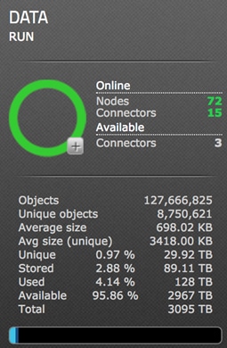
FIO tests were run from clients where vol0 was mounted. The average IO size was 512 for a block size of 1M where fio tests are being run.
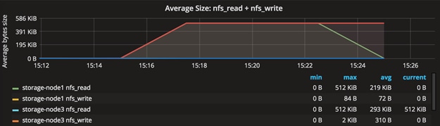
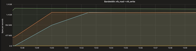
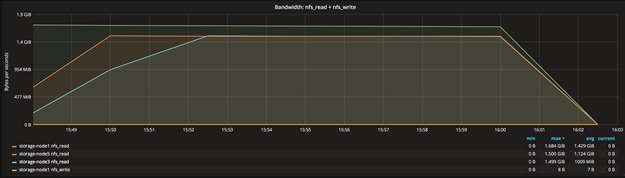
The fault was injected by powering down server 3 from Cisco UCS. The system was doing about 1525 MB/sec at 1M block size before fault was injected.
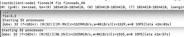
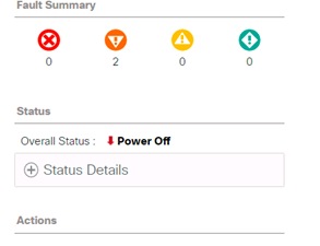
One of the connectors goes down, but it continues on other 2 connectors. Supervisor reports as shown below on its user interface.
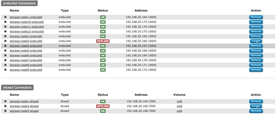
Server brought up again.
The node joins the connectors
[root@supervisor ~]# salt "storage-node[1,3,5]" cmd.run "dstat -n 2 2"
storage-node5:
recv send
0 0
61M 1563M
73M 1557M
storage-node1:
recv send
0 0
94M 1721M
84M 1723M
storage-node3:
recv send
0 0
60M 1550M
80M 1553M
The connector picks up as shown below. The graph depicts that the newly joined node again participates as a connector. It shows how the load ramped up on third connector while the first two were running.
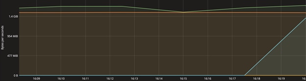
Disk Failure Tests
Disk Failure was simulated to understand the procedure needed from Cisco UCS and the Scality side to replace a failed disk.
The figure below shows the healthy disk on node 4 as reported by Supervisor and Cisco UCS.
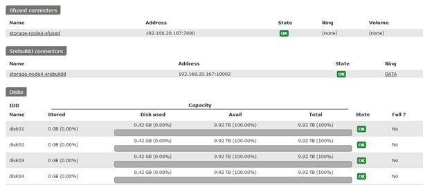
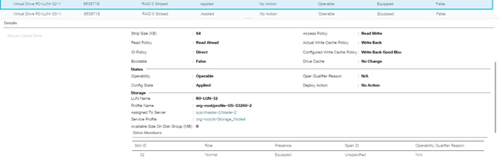
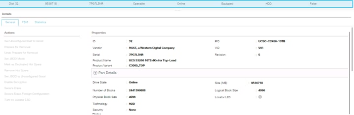
After failing the disk, it displays as a failure in Supervisor.
![]()
This disk has to be replaced with a new disk.
Re-Acknowledged the server:
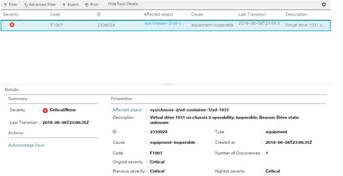
The disk was removed and replaced with a new disk.
If this is a used disk, you may clear foreign configuration in Cisco UCS before assigning it as Unconfigured Good.
The disk is replaced now in Cisco UCS, but supervisor still reports as CONNERR as shown below.
![]()
Disk is visible now to the OS, but there is no partition created.
[root@storage-node4 ~]# cat /proc/partitions | grep sdg
8 96 9765599232 sdg
Cisco UCS shows that lun32 is a RAID-0 Lun
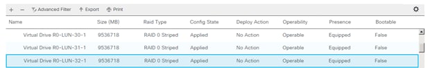
Run Scalilty’s scaldisk command to make the disk join the cluster.
[root@storage-node4 ~]# scaldisk replace -d disk04 -c /dev/sdg
The username has been retrieved in /etc/scality-node-1/userdb/localhost instead of in /etc/scality-node-1/confdb/r0.0/config.xml
Switch on the LED of the disk: disk04
Disk disk04 with basepath /scality/disk04
disk04 is going to be replaced with /dev/sdg
Please confirm [y/N] y
The username has been retrieved in /etc/scality-node-1/userdb/localhost instead of in /etc/scality-node-1/confdb/r0.0/config.xml
Starting biziod for disk04
create a new GPT disk label on /dev/sdg (Module function partition.mklabel executed)
make a primary partition on /dev/sdg (Module function partition.mkpart executed)
name the partition on /dev/sdg (Module function partition.name executed)
reread the partition table on /dev/sdg before formatting (Command "sleep 3 && blockdev --rereadpt /dev/sdg || true" run)
format /dev/sdg1 with an ext4 filesystem (Module function extfs.mkfs executed)
tune the ext4 filesystem on /dev/sdg1 (Module function extfs.tune executed)
leave udev time to update /dev/disk/by-* for /dev/sdg (Command "udevadm settle" run)
mount /scality/disk04 and persist in fstab (check_cmd determined the state succeeded)
update systemd auto generated mount unit (Module function service.systemctl_reload executed)
mount /scality/disk04 if systemd unmounted it (Command "systemctl start --now /scality/disk04" run)
clear OOS PERM flag for disk04, ring DATA (OOS PERM flag is cleared for ring DATA on disk disk04)
/scality/disk04/DATA/0 (Directory /scality/disk04/DATA/0 updated)
ensure biziod for disk04 is running (biziod for disk disk04 is running)
make node DATA-storage-node4-n1 from ring DATA reload keys on disk04 (Node DATA-storage-node4-n1 reloaded keys for ring DATA from disk disk04)
make node DATA-storage-node4-n2 from ring DATA reload keys on disk04 (Node DATA-storage-node4-n2 reloaded keys for ring DATA from disk disk04)
make node DATA-storage-node4-n3 from ring DATA reload keys on disk04 (Node DATA-storage-node4-n3 reloaded keys for ring DATA from disk disk04)
make node DATA-storage-node4-n4 from ring DATA reload keys on disk04 (Node DATA-storage-node4-n4 reloaded keys for ring DATA from disk disk04)
make node DATA-storage-node4-n5 from ring DATA reload keys on disk04 (Node DATA-storage-node4-n5 reloaded keys for ring DATA from disk disk04)
make node DATA-storage-node4-n6 from ring DATA reload keys on disk04 (Node DATA-storage-node4-n6 reloaded keys for ring DATA from disk disk04)
Switch off the LED of the disk: disk04
Disk disk04 with basepath /scality/disk04
[root@storage-node4 ~]#
[root@storage-node4 ~]# df -k | grep disk04
/dev/sdg1 9688468648 341400 9688110864 1% /scality/disk04
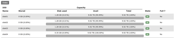
![]() Note: For more information about scaldisk replace, please refer to the Scality documentation.
Note: For more information about scaldisk replace, please refer to the Scality documentation.
This section provides the BOM for the entire Scality Storage and Cisco UCS S3260 solution.
Table 6 Bill of Materials for Cisco Nexus 9332PQ
| Item Name | Description | Quantity |
| N9K-C9332PQ | Nexus 9300 Series, 32p 40G QSFP+ | 2 |
| CON-PSRT-9332PQ | PRTNR SS 8X5XNBD Nexus 9332 ACI Leaf switch with 32p 40G | 2 |
| NXOS-703I5.1 | Nexus 9500, 9300, 3000 Base NX-OS Software Rel 7.0(3)I5(1) | 2 |
| N3K-C3064-ACC-KIT | Nexus 3K/9K Fixed Accessory Kit | 2 |
| QSFP-H40G-CU1M | 40GBASE-CR4 Passive Copper Cable, 1m | 10 |
| NXA-FAN-30CFM-B | Nexus 2K/3K/9K Single Fan, port side intake airflow | 8 |
| CAB-C13-CBN | Cabinet Jumper Power Cord, 250 VAC 10A, C14-C13 Connectors | 4 |
| N9K-PAC-650W | Nexus 9300 650W AC PS, Port-side Intake | 4 |
Table 7 Bill of Materials for Cisco UCS Fabric Interconnect 6332
| Item Name | Description | Quantity |
| UCS-SP-FI6332-2X | UCS SP Select 6332 FI /No PSU/32 QSFP+ | 1 |
| UCS-SP-FI6332 | (Not sold standalone) UCS 6332 1RU FI/No PSU/32 QSFP+ | 2 |
| UCS-PSU-6332-AC | UCS 6332 Power Supply/100-240VAC | 4 |
| CAB-C13-C14-2M | Power Cord Jumper, C13-C14 Connectors, 2 Meter Length | 4 |
| QSFP-H40G-CU3M | 40GBASE-CR4 Passive Copper Cable, 3m | 38 |
| QSFP-40G-SR-BD | QSFP40G BiDi Short-reach Transceiver | 8 |
| N10-MGT014 | UCS Manager v3.1 | 2 |
| UCS-FAN-6332 | UCS 6332 Fan Module | 8 |
| UCS-ACC-6332 | UCS 6332 Chassis Accessory Kit | 2 |
| RACK-UCS2 | Cisco R42610 standard rack, w/side panels | 1 |
| RP230-32-1P-U-2 | Cisco RP230-32-U-2 Single Phase PDU 20x C13, 4x C19 | 2 |
Table 8 Bill of Materials for Cisco UCS S3260 Storage Server
| Item Name | Description | Quantity |
| UCSS-S3260 | Cisco UCS S3260 Storage Server Base Chassis | 6 |
| UCSC-C3X60-10TB | UCS C3X60 10TB 12Gbps NL-SAS 7200RPM HDD w carrier- Top-load | 312 |
| UCS-C3X60-G2SD48 | UCSC C3X60 480GB Boot SSD (Gen 2) | 24 |
| UCSC-PSU1-1050W | UCS C3X60 1050W Power Supply Unit | 24 |
| UCS-C3K-42HD10 | UCS C3X60 3 row of 10TB NL-SAS drives (42 Total) 420TB | 6 |
| UCS-C3X60-12G280 | UCSC C3X60 800GB 12Gbps SSD (Gen 2) | 24 |
| UCSC-C3X60-10TB | UCSC C3X60 10TB 4Kn for Top-Load | xx |
| CAB-C13-CBN | Cabinet Jumper Power Cord, 250 VAC 10A, C14-C13 Connectors | 24 |
| UCSC-C3260-SIOC | Cisco UCS C3260 System IO Controller with VIC 1300 incl. | 12 |
| UCSC-C3X60-RAIL | UCS C3X60 Rack Rails Kit | 6 |
| N20-BBLKD-7MM | UCS 7MM SSD Blank Filler | 12 |
| UCSS-S3260-BBEZEL | Cisco UCS S3260 Bezel | 6 |
| UCSC-C3K-M4SRB | UCS C3000 M4 Server Node for Intel E5-2600 v4 | 12 |
| UCS-CPU-E52650E | 2.20 GHz E5-2650 v4/105W 12C/05MB Cache/DDR4 2400MHz | 24 |
| UCS-MR-1X161RV-A | 16GB DDR4-2400-MHz RDIMM/PC4-19200/single rank/x4/1.2v | 256 |
| UCS-C3K-M4RAID | Cisco UCS C3000 RAID Controller M4 Server w 4G RAID Cache | 12 |
| UCSC-HS-C3X60 | Cisco UCS C3X60 Server Node CPU Heatsink | 24 |
| RHEL-2S2V-1A | Red Hat Enterprise Linux (1-2 CPU,1-2 VN); 1-Yr Support Requirement | 6 |
Table 9 Bill of Material for Cisco UCS C220 M4S
| Item Name | Description | Quantity |
| UCSC-C220-M4S | UCS C220 M4 SFF w/o CPU, mem, HD, PCIe, PSU, rail kit | 1 |
| UCS-CPU-E52683E | 2.10 GHz E5-2683 v4/120W 16C/40MB Cache/DDR4 2400MHz | 2 |
| UCS-MR-1X161RV-A | 16GB DDR4-2400-MHz RDIMM/PC4-19200/single rank/x4/1.2v | 8 |
| UCS-HD600G10K12G | 600GB 12G SAS 10K RPM SFF HDD | 2 |
| UCSC-MLOM-C40Q-03 | Cisco VIC 1387 Dual Port 40Gb QSFP CNA MLOM | 1 |
| UCSC-RAILB-M4 | Ball Bearing Rail Kit for C220 M4 and C240 M4 rack servers | 1 |
| UCSC-PSU1-770W | 770W AC Hot-Plug Power Supply for 1U C-Series Rack Server | 2 |
| CAB-C13-C14-2M | Power Cord Jumper, C13-C14 Connectors, 2 Meter Length | 2 |
| UCS-M4-V4-LBL | Cisco M4 - v4 CPU asset tab ID label (Auto-Expand) | 2 |
| N20-BBLKD | UCS 2.5 inch HDD blanking panel | 6 |
| UCSC-SCCBL220 | Supercap cable 950mm | 1 |
| UCSC-MLOM-BLK | MLOM Blanking Panel | 1 |
| UCSC-HS-C220M4 | Heat sink for UCS C220 M4 rack servers | 2 |
| UCSC-MRAID12G | Cisco 12G SAS Modular Raid Controller | 1 |
| UCSC-MRAID12G-1GB | Cisco 12Gbps SAS 1GB FBWC Cache module (Raid 0/1/5/6) | 1 |
| RHEL-2S2V-1A | Red Hat Enterprise Linux (1-2 CPU,1-2 VN); 1-Yr Support Requirement | 1 |
Appendix A – Kickstart File of Supervisor Node for Cisco UCS C220 M4S
Kickstart File for Supervisor Node
#version=DEVEL
#from the linux installation menu, hit tab and append this:
#biosdevname=0 net.ifnames=0 ip=eth1:dhcp
#ks=ftp://192.168.10.2/{hostname}.cfg
# System authorization information
auth --enableshadow --passalgo=sha512
# Use CDROM installation media
cdrom
# Use text install
text
# Run the Setup Agent on first boot
firstboot --disable
selinux --disable
firewall --disable
# Keyboard layouts
keyboard --vckeymap=us --xlayouts='us'
# System language
lang en_US.UTF-8
# Network information
network --bootproto=static --device=eth0 --ip=128.107.79.201 --netmask=255.255.255.0 --onboot=on --gateway=128.107.79.1 --nameserver=171.70.168.183 --ipv6=auto --activate
network --bootproto=static --device=eth1 --ip=192.168.10.150 --netmask=255.255.255.0 --onboot=on --ipv6=auto --activate
network --bootproto=static --device=eth2 --ip=192.168.20.150 --netmask=255.255.255.0 --onboot=on --ipv6=auto --activate
network --hostname=supervisor
# Root password
rootpw --iscrypted $6$yfE2jHtdy.OSmO8g$InneiVXQI9Kc9m4w2cEiS8/og6BKUlu5HSR0eCYgh5dVaeCV54Q6piS7k10lalXignLCBvAZPqmw4dvYgy66V1
# System services
services --disabled="chronyd"
# System timezone
timezone America/Los_Angeles --isUtc --nontp
# System bootloader configuration
bootloader --append=" crashkernel=auto" --location=mbr --boot-drive=sda
# Partition clearing information
clearpart --drives=sda --all --initlabel
# Disk partitioning information
part /boot --fstype="ext4" --ondisk=sda --size=8192
part swap --fstype="swap" --ondisk=sda --size=32767
part /var --fstype="ext4" --ondisk=sda --grow
part / --fstype="ext4" --ondisk=sda --size=40960
reboot --eject
%packages
@^minimal
@core
kexec-tools
%end
%addon com_redhat_kdump --enable --reserve-mb='auto'
%end
%anaconda
pwpolicy root --minlen=6 --minquality=50 --notstrict --nochanges --notempty
pwpolicy user --minlen=6 --minquality=50 --notstrict --nochanges --notempty
pwpolicy luks --minlen=6 --minquality=50 --notstrict --nochanges --notempty
%end
###############
#POST SCRIPT
###############
%post --log=/root/ks-post.log
###############
#GPT Labels for HDDs
###############
for i in a b {d..z} aa ab ac; do parted -s /dev/sd$i mklabel gpt; done;
###############
#Turn off Transparent Hugepages and ensure that hyperthreading
#is turned off.
###############
grubby --update-kernel=ALL --args="transparent_hugepage=never numa=off";
tuned-adm profile latency-performance;
systemctl enable ntpd;
###############
#Preconfigure /etc/hosts
###############
cat >> /etc/hosts <<EOF4
192.168.10.150 supervisor salt
192.168.10.164 storage-node1
192.168.10.165 storage-node2
192.168.10.166 storage-node3
192.168.10.167 storage-node4
192.168.10.168 storage-node5
192.168.10.169 storage-node6
192.168.10.170 storage-node7
192.168.10.171 storage-node8
192.168.10.172 storage-node9
192.168.10.173 storage-node10
192.168.10.174 storage-node11
192.168.10.175 storage-node12
EOF4
###############
#Setup ssh keys
###############
mkdir /root/.ssh;
cat > /root/.ssh/id_rsa <<EOF5
-----BEGIN RSA PRIVATE KEY-----
MIIEpAIBAAKCAQEAsYGqxWxQdGUsiUzafYLuX6MVD3mjq3r6KaL0QcNSuZ8F3Xfw
7WJWjmhuu/rurLVoA90fjZDQY6aEAdHSH+o27mH6hfkMVqyunwQ6u3MtUqqkwRK2
NtEJqJBiHZw9+bmgofyFYl5wBSWPGIig0kb8m+cBm0uRoE5SFFuAGc7usHkfIFlO
QQd9vz9h6OX8ba3c6yUAZDzWSnt2udyLOTqV4SPpQY4O2NvYgm1VpblHvUvmP7Yu
5yl8hxn0in+RmferTq8WwyZihMV0EyN4q5HfT+gdbSY6xPMM9UHF89+lYNNxdZ4/
VuBcbBskey3UbQ332KqA7wS+Sra2DXmnfysWbwIDAQABAoIBAQCbeRFUXiyR5lP9
5lyw9k9HYRX/OfGLLumSMnJyb1wzzP9cHcPeh/V8QihLadxHVZTHXZRXcHG19pFE
7rx2y7RVU2gUlDCkchd4nEG9EYKvF1u66GLE3I7zH5Nwj/sQkfAKMZ26rTC8sUsG
mBUUWKzE+K7FkIj6ud7WidZHxKH32ok1lEcFOsH/nK1BXR29XmQ/O/Kg2h0V/KiM
1Y9CJngpghnybcDzlvpV6LS8bEiRieHJGT5RTyDk+ad0uSv+f2YtlpvSUIy7NAft
e1feAq3RWT82ZGyKTHWGTFNbfltcUjzPI/dcyS8AurYf+oQjJVAKhAl+yIn7lUrL
V6xKsdYBAoGBANwNb96gJHZUeSoOP/JCnTps+MeOhT1vyrhRRZf1IaFnEmX7hXmE
RKXaQUvGcOSPumZMkKYyqRN22B2PLM7n1D0ypKshRmk1eq6tZ/W9gkYfIdn0+QAx
AAVfUA8vJm9XLgkCAE4o2BHvtQ1w63CfygoF4V3OAsQv677F6ItROeiBAoGBAM6A
9quEOrPiRDiF25HnXXFUeRUXM4H77QB6WRV3AKggJjVlBXkhNt34g8Jr6/MfW4WO
SebQEwwBYH6NN7IG1Q0PeDRzrcv2voqzM7bV7l1rpc2E2BQhplcSyGr/aA6lW0OA
Ll/HZIdqb6OXXR8ImcP0rfxuqUJ8e6SHskG6qAbvAoGAIrw4QXMT7l3NNndDXtFn
EjbrWkzD+XuxC0FA9Aisw1aKz/BRFGptj6SRFA4B+gI6ETXay3FJwRnMaXYVQ5/S
n8pjteOtwqO/dt1GgMLmUn1NkaMavw39C9wMvijaL08apC9drvjBiqtE8Bc4AvIm
KUjeVzlStHdABkAlQgCTXIECgYEAur6BU4YWmAnsa7kRYRZ7uDsN7Ha4y7mJED+U
RAcD/wZjxzF+C5ZvybgtXyq9i3U2DMcqKaLNNrQgERGf5kyrak4tBDIAX0zZ7xAz
mgpIrw7kN8EErt/nTyLbP3eNIIGE0LwgM9lbHeKw5p3BRok+lKi2lmt0gX2VSqq0
FyC3Rt0CgYADqOJ53sV7NEXfd/NG5D9bzS5yCKW+KNH4fzxAoAYhMBo3nAkgpa/1
rdjPH4f5bAMX6dKZCh5Sy9BFxgqbI0tdjVGZBUPK8tb0xbcnJ2F3+aLq02fCfyr+
TfYW1tZ7g7gZJ+To42h4Tv9wj8iWGe+pnR4Moh3WqM1TttuaCJf1nQ==
-----END RSA PRIVATE KEY-----
EOF5
cat > /root/.ssh/id_rsa.pub <<EOF6
ssh-rsa AAAAB3NzaC1yc2EAAAADAQABAAABAQCxgarFbFB0ZSyJTNp9gu5foxUPeaOrevopovRBw1K5nwXdd/DtYlaOaG67+u6stWgD3R+NkNBjpoQB0dIf6jbuYfqF+QxWrK6fBDq7cy1SqqTBErY20QmokGIdnD35uaCh/IViXnAFJY8YiKDSRvyb5wGbS5GgTlIUW4AZzu6weR8gWU5BB32/P2Ho5fxtrdzrJQBkPNZKe3a53Is5OpXhI+lBjg7Y29iCbVWluUe9S+Y/ti7nKXyHGfSKf5GZ96tOrxbDJmKExXQTI3irkd9P6B1tJjrE8wz1QcXz36Vg03F1nj9W4FxsGyR7LdRtDffYqoDvBL5KtrYNead/KxZv root@storage-node7
EOF6
cat > /root/.ssh/authorized_keys <<EOF7
ssh-rsa AAAAB3NzaC1yc2EAAAADAQABAAABAQCxgarFbFB0ZSyJTNp9gu5foxUPeaOrevopovRBw1K5nwXdd/DtYlaOaG67+u6stWgD3R+NkNBjpoQB0dIf6jbuYfqF+QxWrK6fBDq7cy1SqqTBErY20QmokGIdnD35uaCh/IViXnAFJY8YiKDSRvyb5wGbS5GgTlIUW4AZzu6weR8gWU5BB32/P2Ho5fxtrdzrJQBkPNZKe3a53Is5OpXhI+lBjg7Y29iCbVWluUe9S+Y/ti7nKXyHGfSKf5GZ96tOrxbDJmKExXQTI3irkd9P6B1tJjrE8wz1QcXz36Vg03F1nj9W4FxsGyR7LdRtDffYqoDvBL5KtrYNead/KxZv root@storage-node7
EOF7
chmod 700 /root/.ssh;
chmod 600 /root/.ssh/authorized_keys;
chmod 600 /root/.ssh/id_rsa;
chmod 644 /root/.ssh/id_rsa.pub;
###############
# Remove NetworkManager, a core package which is not needed.
yum -y remove NetworkManager;
%end
Appendix B – Kickstart File of Storage Nodes for Cisco UCS S3260 M4 Server
Kickstart File for Storage-node1
#version=DEVEL
#from the linux installation menu, hit tab and append this:
#biosdevname=0 net.ifnames=0 ip=eth1:dhcp
#ks=ftp://192.168.10.2/{hostname}.cfg
# System authorization information
auth --enableshadow --passalgo=sha512
# Use CDROM installation media
cdrom
# Use text install
text
# Run the Setup Agent on first boot
firstboot --disable
selinux --disable
firewall --disable
# Keyboard layouts
keyboard --vckeymap=us --xlayouts='us'
# System language
lang en_US.UTF-8
# Network information
network --bootproto=static --device=eth0 --ip=128.107.79.205 --netmask=255.255.255.0 --onboot=on --gateway=128.107.79.1 --nameserver=171.70.168.183 --ipv6=auto --activate
network --bootproto=static --device=eth1 --ip=192.168.10.164 --netmask=255.255.255.0 --onboot=on --ipv6=auto --activate
network --bootproto=static --device=eth2 --ip=192.168.20.164 --netmask=255.255.255.0 --onboot=on --ipv6=auto --activate
network --hostname=storage-node1
# Root password
rootpw --iscrypted $6$yfE2jHtdy.OSmO8g$InneiVXQI9Kc9m4w2cEiS8/og6BKUlu5HSR0eCYgh5dVaeCV54Q6piS7k10lalXignLCBvAZPqmw4dvYgy66V1
# System services
services --disabled="chronyd"
# System timezone
timezone America/Los_Angeles --isUtc --nontp
# System bootloader configuration
bootloader --append=" crashkernel=auto" --location=mbr --boot-drive=sdc
# Partition clearing information
clearpart --drives=sdc --all --initlabel
# Disk partitioning information
part /boot --fstype="ext4" --ondisk=sdc --size=8192
part swap --fstype="swap" --ondisk=sdc --size=32767
part /var --fstype="ext4" --ondisk=sdc --grow
part / --fstype="ext4" --ondisk=sdc --size=40960
reboot --eject
%packages
@^minimal
@core
kexec-tools
%end
%addon com_redhat_kdump --enable --reserve-mb='auto'
%end
%anaconda
pwpolicy root --minlen=6 --minquality=50 --notstrict --nochanges --notempty
pwpolicy user --minlen=6 --minquality=50 --notstrict --nochanges --notempty
pwpolicy luks --minlen=6 --minquality=50 --notstrict --nochanges --notempty
%end
###############
#POST SCRIPT
###############
%post --log=/root/ks-post.log
###############
#GPT Labels for HDDs
###############
for i in a b {d..z} aa ab ac; do parted -s /dev/sd$i mklabel gpt; done;
###############
#Turn off Transparent Hugepages and ensure that hyperthreading
#is turned off.
###############
grubby --update-kernel=ALL --args="transparent_hugepage=never numa=off nr_cpus=24";
tuned-adm profile latency-performance;
systemctl enable ntpd;
###############
#Preconfigure /etc/hosts
###############
cat >> /etc/hosts <<EOF4
192.168.10.150 supervisor salt
192.168.10.164 storage-node1
192.168.10.165 storage-node2
192.168.10.166 storage-node3
192.168.10.167 storage-node4
192.168.10.168 storage-node5
192.168.10.169 storage-node6
192.168.10.170 storage-node7
192.168.10.171 storage-node8
192.168.10.172 storage-node9
192.168.10.173 storage-node10
192.168.10.174 storage-node11
192.168.10.175 storage-node12
EOF4
###############
#Setup ssh keys
###############
mkdir /root/.ssh;
cat > /root/.ssh/id_rsa <<EOF5
-----BEGIN RSA PRIVATE KEY-----
MIIEpAIBAAKCAQEAsYGqxWxQdGUsiUzafYLuX6MVD3mjq3r6KaL0QcNSuZ8F3Xfw
7WJWjmhuu/rurLVoA90fjZDQY6aEAdHSH+o27mH6hfkMVqyunwQ6u3MtUqqkwRK2
NtEJqJBiHZw9+bmgofyFYl5wBSWPGIig0kb8m+cBm0uRoE5SFFuAGc7usHkfIFlO
QQd9vz9h6OX8ba3c6yUAZDzWSnt2udyLOTqV4SPpQY4O2NvYgm1VpblHvUvmP7Yu
5yl8hxn0in+RmferTq8WwyZihMV0EyN4q5HfT+gdbSY6xPMM9UHF89+lYNNxdZ4/
VuBcbBskey3UbQ332KqA7wS+Sra2DXmnfysWbwIDAQABAoIBAQCbeRFUXiyR5lP9
5lyw9k9HYRX/OfGLLumSMnJyb1wzzP9cHcPeh/V8QihLadxHVZTHXZRXcHG19pFE
7rx2y7RVU2gUlDCkchd4nEG9EYKvF1u66GLE3I7zH5Nwj/sQkfAKMZ26rTC8sUsG
mBUUWKzE+K7FkIj6ud7WidZHxKH32ok1lEcFOsH/nK1BXR29XmQ/O/Kg2h0V/KiM
1Y9CJngpghnybcDzlvpV6LS8bEiRieHJGT5RTyDk+ad0uSv+f2YtlpvSUIy7NAft
e1feAq3RWT82ZGyKTHWGTFNbfltcUjzPI/dcyS8AurYf+oQjJVAKhAl+yIn7lUrL
V6xKsdYBAoGBANwNb96gJHZUeSoOP/JCnTps+MeOhT1vyrhRRZf1IaFnEmX7hXmE
RKXaQUvGcOSPumZMkKYyqRN22B2PLM7n1D0ypKshRmk1eq6tZ/W9gkYfIdn0+QAx
AAVfUA8vJm9XLgkCAE4o2BHvtQ1w63CfygoF4V3OAsQv677F6ItROeiBAoGBAM6A
9quEOrPiRDiF25HnXXFUeRUXM4H77QB6WRV3AKggJjVlBXkhNt34g8Jr6/MfW4WO
SebQEwwBYH6NN7IG1Q0PeDRzrcv2voqzM7bV7l1rpc2E2BQhplcSyGr/aA6lW0OA
Ll/HZIdqb6OXXR8ImcP0rfxuqUJ8e6SHskG6qAbvAoGAIrw4QXMT7l3NNndDXtFn
EjbrWkzD+XuxC0FA9Aisw1aKz/BRFGptj6SRFA4B+gI6ETXay3FJwRnMaXYVQ5/S
n8pjteOtwqO/dt1GgMLmUn1NkaMavw39C9wMvijaL08apC9drvjBiqtE8Bc4AvIm
KUjeVzlStHdABkAlQgCTXIECgYEAur6BU4YWmAnsa7kRYRZ7uDsN7Ha4y7mJED+U
RAcD/wZjxzF+C5ZvybgtXyq9i3U2DMcqKaLNNrQgERGf5kyrak4tBDIAX0zZ7xAz
mgpIrw7kN8EErt/nTyLbP3eNIIGE0LwgM9lbHeKw5p3BRok+lKi2lmt0gX2VSqq0
FyC3Rt0CgYADqOJ53sV7NEXfd/NG5D9bzS5yCKW+KNH4fzxAoAYhMBo3nAkgpa/1
rdjPH4f5bAMX6dKZCh5Sy9BFxgqbI0tdjVGZBUPK8tb0xbcnJ2F3+aLq02fCfyr+
TfYW1tZ7g7gZJ+To42h4Tv9wj8iWGe+pnR4Moh3WqM1TttuaCJf1nQ==
-----END RSA PRIVATE KEY-----
EOF5
cat > /root/.ssh/id_rsa.pub <<EOF6
ssh-rsa AAAAB3NzaC1yc2EAAAADAQABAAABAQCxgarFbFB0ZSyJTNp9gu5foxUPeaOrevopovRBw1K5nwXdd/DtYlaOaG67+u6stWgD3R+NkNBjpoQB0dIf6jbuYfqF+QxWrK6fBDq7cy1SqqTBErY20QmokGIdnD35uaCh/IViXnAFJY8YiKDSRvyb5wGbS5GgTlIUW4AZzu6weR8gWU5BB32/P2Ho5fxtrdzrJQBkPNZKe3a53Is5OpXhI+lBjg7Y29iCbVWluUe9S+Y/ti7nKXyHGfSKf5GZ96tOrxbDJmKExXQTI3irkd9P6B1tJjrE8wz1QcXz36Vg03F1nj9W4FxsGyR7LdRtDffYqoDvBL5KtrYNead/KxZv root@storage-node7
EOF6
cat > /root/.ssh/authorized_keys <<EOF7
ssh-rsa AAAAB3NzaC1yc2EAAAADAQABAAABAQCxgarFbFB0ZSyJTNp9gu5foxUPeaOrevopovRBw1K5nwXdd/DtYlaOaG67+u6stWgD3R+NkNBjpoQB0dIf6jbuYfqF+QxWrK6fBDq7cy1SqqTBErY20QmokGIdnD35uaCh/IViXnAFJY8YiKDSRvyb5wGbS5GgTlIUW4AZzu6weR8gWU5BB32/P2Ho5fxtrdzrJQBkPNZKe3a53Is5OpXhI+lBjg7Y29iCbVWluUe9S+Y/ti7nKXyHGfSKf5GZ96tOrxbDJmKExXQTI3irkd9P6B1tJjrE8wz1QcXz36Vg03F1nj9W4FxsGyR7LdRtDffYqoDvBL5KtrYNead/KxZv root@storage-node7
EOF7
chmod 700 /root/.ssh;
chmod 600 /root/.ssh/authorized_keys;
chmod 600 /root/.ssh/id_rsa;
chmod 644 /root/.ssh/id_rsa.pub;
###############
# Remove NetworkManger, a core package which is not needed.
yum -y remove NetworkManager;
%end
Vijay Durairaj, Cisco Systems, Inc.
Vijay Durairaj is a Technical Marketing Engineer in Cisco UCS and Data Center Solutions Group. Vijay has over 15 years of experience in IT Infrastructure, Server Virtualization and Cloud Computing. His current role includes building Cloud Computing Solutions, Software defined Storage solutions and Performance benchmarking on Cisco UCS platforms. Vijay also holds Cisco Unified Computing Design Certification.
William Kettler, Scality
William Kettler is a Customer Solution Engineer Partner within Scality’s Technical Services group. His current role includes helping customers deploy their petabyte-scale storage solutions, certifying strategic ISVs, and being a technical resource for Scality partners like Cisco.
Acknowledgements
For their support and contribution to the design, validation, and creation of this Cisco Validated Design, we would like to acknowledge the following people for their significant contribution and expertise that resulted in developing this document:
· RamaKrishna Nishtala, Cisco Systems, Inc.
· Jawwad Memon, Cisco Systems, Inc.
 Feedback