FlashStack Virtual Server Infrastructure with Fibre Channel Storage for VMware vSphere 6.5 U1
Available Languages

FlashStack Virtual Server Infrastructure with Fibre Channel Storage for VMware vSphere 6.5 U1
Fibre Channel Deployment Guide for FlashStack with Cisco UCS 6300 Fabric Interconnect and Pure Storage FlashArray//X70
Last Updated: March 6, 2018

About the Cisco Validated Design Program
The Cisco Validated Design (CVD) program consists of systems and solutions designed, tested, and documented to facilitate faster, more reliable, and more predictable customer deployments. For more information, visit:
http://www.cisco.com/go/designzone.
ALL DESIGNS, SPECIFICATIONS, STATEMENTS, INFORMATION, AND RECOMMENDATIONS (COLLECTIVELY, "DESIGNS") IN THIS MANUAL ARE PRESENTED "AS IS," WITH ALL FAULTS. CISCO AND ITS SUPPLIERS DISCLAIM ALL WARRANTIES, INCLUDING, WITHOUT LIMITATION, THE WARRANTY OF MERCHANTABILITY, FITNESS FOR A PARTICULAR PURPOSE AND NONINFRINGEMENT OR ARISING FROM A COURSE OF DEALING, USAGE, OR TRADE PRACTICE. IN NO EVENT SHALL CISCO OR ITS SUPPLIERS BE LIABLE FOR ANY INDIRECT, SPECIAL, CONSEQUENTIAL, OR INCIDENTAL DAMAGES, INCLUDING, WITHOUT LIMITATION, LOST PROFITS OR LOSS OR DAMAGE TO DATA ARISING OUT OF THE USE OR INABILITY TO USE THE DESIGNS, EVEN IF CISCO OR ITS SUPPLIERS HAVE BEEN ADVISED OF THE POSSIBILITY OF SUCH DAMAGES.
THE DESIGNS ARE SUBJECT TO CHANGE WITHOUT NOTICE. USERS ARE SOLELY RESPONSIBLE FOR THEIR APPLICATION OF THE DESIGNS. THE DESIGNS DO NOT CONSTITUTE THE TECHNICAL OR OTHER PROFESSIONAL ADVICE OF CISCO, ITS SUPPLIERS OR PARTNERS. USERS SHOULD CONSULT THEIR OWN TECHNICAL ADVISORS BEFORE IMPLEMENTING THE DESIGNS. RESULTS MAY VARY DEPENDING ON FACTORS NOT TESTED BY CISCO.
CCDE, CCENT, Cisco Eos, Cisco Lumin, Cisco Nexus, Cisco StadiumVision, Cisco TelePresence, Cisco WebEx, the Cisco logo, DCE, and Welcome to the Human Network are trademarks; Changing the Way We Work, Live, Play, and Learn and Cisco Store are service marks; and Access Registrar, Aironet, AsyncOS, Bringing the Meeting To You, Catalyst, CCDA, CCDP, CCIE, CCIP, CCNA, CCNP, CCSP, CCVP, Cisco, the Cisco Certified Internetwork Expert logo, Cisco IOS, Cisco Press, Cisco Systems, Cisco Systems Capital, the Cisco Systems logo, Cisco Unified Computing System (Cisco UCS), Cisco UCS B-Series Blade Servers, Cisco UCS C-Series Rack Servers, Cisco UCS S-Series Storage Servers, Cisco UCS Manager, Cisco UCS Management Software, Cisco Unified Fabric, Cisco Application Centric Infrastructure, Cisco Nexus 9000 Series, Cisco Nexus 7000 Series. Cisco Prime Data Center Network Manager, Cisco NX-OS Software, Cisco MDS Series, Cisco Unity, Collaboration Without Limitation, EtherFast, EtherSwitch, Event Center, Fast Step, Follow Me Browsing, FormShare, GigaDrive, HomeLink, Internet Quotient, IOS, iPhone, iQuick Study, LightStream, Linksys, MediaTone, MeetingPlace, MeetingPlace Chime Sound, MGX, Networkers, Networking Academy, Network Registrar, PCNow, PIX, PowerPanels, ProConnect, ScriptShare, SenderBase, SMARTnet, Spectrum Expert, StackWise, The Fastest Way to Increase Your Internet Quotient, TransPath, WebEx, and the WebEx logo are registered trademarks of Cisco Systems, Inc. and/or its affiliates in the United States and certain other countries.
All other trademarks mentioned in this document or website are the property of their respective owners. The use of the word partner does not imply a partnership relationship between Cisco and any other company. (0809R)
© 2018 Cisco Systems, Inc. All rights reserved.
Table of Contents
FlashStack Nexus Switch Configuration
Setting the NX-OS image on the Switch
Cisco Nexus Basic System Configuration Dialog
Cisco Nexus Switch Configuration
Add Individual Port Descriptions for Troubleshooting
Add NTP Distribution Interfaces
Configure Port Channel Member Interfaces
Configure Virtual Port Channels
FlashArray Storage Configuration
FlashArray Initial Configuration
Configuring the Domain Name System (DNS) Server IP Addresses
MDS Basic System Configuration Dialog
Upgrade Cisco MDS NX-OS release 6.2(21)
Cisco UCS Compute Configuration
Upgrade Cisco UCS Manager Software to Version 3.2(1d)
Enable Server and Uplink Ports
Configure UCS LAN Connectivity
Set Jumbo Frames in Cisco UCS Fabric
Create LAN Connectivity Policy
Create SAN Connectivity Policy
Create Service Profile Template
Create vMedia Service Profile Template
Create Device Aliases for the Connected FlashArray Ports
Private Volumes for each ESXi Host
Log in to Cisco UCS 6332-16UP Fabric Interconnect
Set Up VMware ESXi Installation
Set Up Management Networking for ESXi Hosts
Create VMware vDS for Infrastructure and Application Traffic
Add the VMware ESXi Hosts Using the VMware vSphere Web Client
Pure Storage vSphere Web Client Plugin
Configure ESXi Hosts in the Cluster
Install VMware Driver for the Cisco Virtual Interface Card (VIC)
Create vMotion VMkernel adapters
Cisco UCS Manager Plug-in for VMware vSphere Web Client
Cisco UCS Manager Plug-in Installation
FlashStack UCS Domain Registration
Using the Cisco UCS vCenter Plugin
Pure Storage Best Practices for vSphere
Cisco Validated Designs consist of systems and solutions that are designed, tested, and documented to facilitate and improve customer deployments. These designs incorporate a wide range of technologies and products into a portfolio of solutions that have been developed to address the business needs of our customers.
This document details the design in the FlashStack Virtual Server Infrastructure Design Guide for VMware vSphere 6.5 U1, which describes a validated converged infrastructure jointly developed by Cisco and Pure Storage. This solution covers the deployment of a predesigned, best-practice data center architecture with VMware vSphere built on the Cisco Unified Computing System (UCS), the Cisco Nexus® 9000 family of switches, Cisco MDS 9000 family of Fibre Channel switches, and Pure Storage FlashArray//X all flash storage configured for Fibre Channel based storage access.
When deployed, the architecture presents a robust infrastructure viable for a wide range of application workloads implemented as a virtual server infrastructure.
Introduction
In the current industry there is a trend for pre-engineered solutions which standardize the data center infrastructure, offering the business operational efficiencies, agility and scale to address cloud, bimodal IT and their business. Their challenge is complexity, diverse application support, efficiency and risk; all these are met by FlashStack with:
· Reduced complexity and automatable infrastructure and easily deployed resources
· Robust components capable of supporting high performance and high bandwidth virtualized applications
· Efficiency through optimization of network bandwidth and in-line storage compression with de-duplication
· Risk reduction at each level of the design with resiliency built into each touch point throughout
Cisco and Pure Storage have partnered to deliver this Cisco Validated Design, which uses best of breed storage, server and network components to serve as the foundation for virtualized workloads, enabling efficient architectural designs that can be quickly and confidently deployed.
In this document we will describe a reference architecture detailing a Virtual Server Infrastructure composed of Cisco Nexus switches, Cisco UCS Compute, Cisco MDS Multilayer Fabric Switches and a Pure Storage FlashArray//X delivering a VMware vSphere 6.5 U1 hypervisor environment.
Audience
The audience for this document includes, but is not limited to; sales engineers, field consultants, professional services, IT managers, partner engineers, and customers who want to take advantage of an infrastructure built to deliver IT efficiency and enable IT innovation.
Purpose of this Document
This document details a step-by-step configuration and implementation guide for FlashStack, centered around the Cisco UCS 6332-16UP Fabric Interconnect and the Pure Storage FlashArray//X70. These components are supported by the 100G capable Cisco Nexus 93180YC-EX switch and the Cisco MDS 9148S Multilayer fabric switch to deliver a Virtual Server infrastructure on Cisco UCS B200 M5 Blade Servers running VMware vSphere 6.5 U1.
The design that will be implemented is discussed in the FlashStack Virtual Server Infrastructure Design Guide for VMware vSphere 6.5 U1 found at:
Solution Summary
The FlashStack Virtual Server Infrastructure is a validated reference architecture, collaborated on by Cisco and Pure Storage, built to serve enterprise datacenters. The solution is built to deliver a VMware vSphere based environment, leveraging the Cisco Unified Computing System (UCS), Cisco Nexus switches, Cisco MDS Multilayer Fabric switches, and Pure Storage FlashArray.
The architecture brings together a simple, wire once solution that is SAN booted from fibre channel and highly resilient at each layer of the design. This creates an infrastructure that is ideal for a variety of virtual application deployments that can reliably scale when growth is needed.
Figure 1 shows the base physical architecture used in FlashStack Virtual Server Infrastructure.
Figure 1 FlashStack with Cisco UCS 6332-16UP and Pure Storage FlashArray//X70
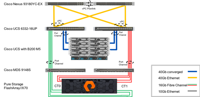
The reference hardware configuration includes:
· Two Cisco Nexus 93180YC-EX Switches
· Two Cisco UCS 6332-16UP Fabric Interconnects
· Cisco UCS 5108 Chassis with two Cisco UCS 2304 Fabric Extenders
· Cisco UCS B200 M5 Blade Servers
· Two Cisco MDS 9148S Multilayer Fabric Switches
· A Pure Storage FlashArray//X70
The virtual environment this supports is within VMware vSphere 6.5 U1, and includes virtual management and automation components from Cisco and Pure Storage built into the solution, or as optional add-ons.
This document will provide a low-level example of steps to deploy this base architecture that may need some adjustments depending on the customer environment. These steps include physical cabling, network, storage, compute, and virtual device configurations.
Software Revisions
Table 1 lists the software versions for hardware and virtual components used in this solution. Each of these versions have been used have been certified within interoperability matrixes supported by Cisco, Pure Storage, and VMware. For more current supported version information, consult the following sources:
· Cisco UCS Hardware and Software Interoperability Tool: http://www.cisco.com/web/techdoc/ucs/interoperability/matrix/matrix.html
· Pure Storage Interoperability(note, this interoperability list will require a support login form Pure): https://support.purestorage.com/FlashArray/Getting_Started/Compatibility_Matrix
· VMware Compatibility Guide: http://www.vmware.com/resources/compatibility/search.php
Additionally, it is also strongly suggested to align FlashStack deployments with the recommended releases for Cisco MDS 9000 Series Switches and Cisco Nexus 9000 switches used in the architecture:
If versions are selected that differ from the validated versions below, it is highly recommended to read the release notes of the selected version to be aware of any changes to features or commands that may have occurred.
| Layer | Device | Image | Comments |
| Compute | Cisco UCS Fabric Interconnects 6300 Series, UCS B-200 M5 | 3.2(1d) | Includes the Cisco UCS IOM 2304 and Cisco UCS VIC 1340 Cisco source |
| Network | Cisco Nexus 9000 NX-OS | 7.0(3)I5(2) |
|
| Storage | Cisco MDS 9148S | 6.2(21) |
|
|
| Pure Storage FlashArray//X70 | 4.10.5 |
|
| Software | Cisco UCS Manager | 3.2(1d) | |
|
| VMware vSphere ESXi Cisco Custom ISO | 6.5 U1 | |
|
| VMware vSphere fnic driver for ESXi | 1.6.0.34 | Included in 6.5 U1 Cisco Custom ISO |
|
| VMware vSphere nenic driver for ESXi | 1.0.6.0 | Included in 6.5 U1 Cisco Custom ISO |
|
| VMware vCenter | 6.5 U1 |
|
|
| Pure Storage vSphere Web Client Plugin | 3.0 | The 2.5.1 version is provided with Purity 4.10.5, but will default to provisioning of VMFS-5 datastores within the plugin. To enable the option of VMFS-6 through the plugin, a support request can be made with Pure to enable access to the 3.0 plugin. |
|
| Cisco UCSM plugin for the Sphere Web Client | 2.0.3 |
|
Configuration Guidelines
This document details the step-by-step configuration of a fully redundant and highly available Virtual Server Infrastructure built on Cisco and Pure Storage components. References are made to which component is being configured with each step, either 01 or 02 or A and B. For example, controller-1 and controller-2 are used to identify the two controllers within the Pure Storage FlashArray//X that are provisioned with this document, and Cisco Nexus A or Cisco Nexus B identifies the pair of Cisco Nexus switches that are configured. The Cisco UCS fabric interconnects are similarly configured. Additionally, this document details the steps for provisioning multiple Cisco UCS hosts, and these examples are identified as: VM-Host-FC-01, VM-Host-FC-02 to represent infrastructure and production hosts deployed to the fabric interconnects in this document. Finally, to indicate that you should include information pertinent to your environment in a given step, <<text>> appears as part of the command structure. Refer to the following example during a configuration step for both Nexus switches:
b19-93180-1&2 (config)# ntp server <<var_oob_ntp>> use-vrf management
This document is intended to enable you to fully configure the customer environment. In this process, various steps require you to insert customer-specific naming conventions, IP addresses, and VLAN schemes, as well as to record appropriate MAC addresses. Table 2 describes the VLANs necessary for deployment as outlined in this guide, and Table 3 lists the virtual machines (VMs) necessary for deployment as outlined in this guide.
| VLAN Name | VLAN Purpose | ID Used in Validating this Document | Customer Deployed Value |
| Native | VLAN to which untagged frames are assigned | 2 |
|
| Out of Band Mgmt | VLAN for out-of-band management interfaces | 15 |
|
| In-Band Mgmt | VLAN for in-band management interfaces | 115 |
|
| vMotion | VLAN for VMware vMotion | 200 |
|
| VM-App1 | VLAN for Production VM Interfaces | 201 |
|
| VM-App2 | VLAN for Production VM Interfaces | 202 |
|
| VM-App2 | VLAN for Production VM Interfaces | 203 |
|
Table 3 Infrastructure Virtual Machines
| Virtual Machine Description | VM Name Used in Validating This Document | Customer Deployed Value |
| Active Directory | Pure-AD |
|
| vCenter Server | Pure-VC |
|
Table 4 Configuration Variables
| Variable | Variable Description | Customer Deployed Value |
| <<var_nexus_A_hostname>> | Nexus switch A hostname (Example: b19-93180-1) |
|
| <<var_nexus_A_mgmt_ip>> | Out-of-band management IP for Nexus switch A (Example: 192.168.164.13) |
|
| <<var_oob_mgmt_mask>> | Out-of-band management network netmask (Example: 255.255.255.0) |
|
| <<var_oob_gateway>> | Out-of-band management network gateway (Example: 192.168.164.254) |
|
| <<var_oob_ntp>> | Out-of-band management network NTP server (Example: 192.168.164.254) |
|
| <<var_nexus_B_hostname>> | Nexus switch B hostname (Example: b19-93180-2) |
|
| <<var_nexus_B_mgmt_ip>> | Out-of-band management IP for Nexus switch B (Example: 192.168.164.14) |
|
| <<var_nexus_A_ib_ip>> | In-band management network interface for Nexus switch A (Example: 10.1.164.13) |
|
| <<var_nexus_B_ib_ip>> | In-band management network interface for Nexus switch B (Example: 10.1.164.14) |
|
| <<var_flasharray_hostname>> | Array hostname set during setup (Example: flashstack-1) |
|
| <<var_flasharray_vip>> | Virtual IP that will answer for the active management controller (Example: 192.168.164.40 |
|
| <<var_contoller-1_mgmt_ip>> | Out-of-band management IP for FlashArray controller-1 (Example: 192.168.164.41) |
|
| <<var_ contoller-1_mgmt_mask>> | Out-of-band management network netmask (Example: 255.255.255.0) |
|
| <<var_ contoller-1_mgmt_gateway>> | Out-of-band management network default gateway (Example: 192.168.164.254) |
|
| <<var_ contoller-2_mgmt_ip>> | Out-of-band management IP for FlashArray controller-2 (Example: 192.168.164.42) |
|
| <<var_ contoller-2_mgmt_mask>> | Out-of-band management network netmask (Example: 255.255.255.0) |
|
| <<var_ contoller-2_mgmt_gateway>> | Out-of-band management network default gateway (Example: 192.168.164.1) |
|
| <<var_password>> | Administrative password (Example: Fl@shSt4x) |
|
| <<var_dns_domain_name>> | DNS domain name (Example: flashstack.cisco.com) |
|
| <<var_nameserver_ip>> | DNS server IP(s) (Example: 10.1.164.9) |
|
| <<var_smtp_ip>> | Email Relay Server IP Address or FQDN (Example: smtp.flashstack.cisco.com) |
|
| <<var_smtp_domain_name>> | Email Domain Name (Example: flashstack.cisco.com) |
|
| <<var_timezone>> | FlashStack time zone (Example: America/New_York) |
|
| <<var_oob_mgmt_vlan_id>> | Out-of-band management network VLAN ID (Example: 15) |
|
| <<var_ib_mgmt_vlan_id>> | In-band management network VLAN ID (Example: 115) |
|
| <<var_ib_mgmt_vlan_netmask_length>> | Length of IB-MGMT-VLAN Netmask (Example: /24) |
|
| <<var_ib_gateway_ip>> | In-band management network VLAN ID (Example: 10.1.164.254) |
|
| <<var_vmotion_vlan_id>> | In-band management network VLAN ID (Example: 200) |
|
| <<var_vmotion_vlan_netmask_length>> | Length of IB-MGMT-VLAN Netmask (Example: /24) |
|
| <<var_native_vlan_id>> | Native network VLAN ID (Example: 2) |
|
| <<var_app_vlan_id>> | Example Application network VLAN ID (Example: 201) |
|
| <<var_snmp_contact>> | Administrator e-mail address (Example: admin@flashstack.cisco.com) |
|
| <<var_snmp_location>> | Cluster location string (Example: RTP9-B19) |
|
| <<var_mds_A_mgmt_ip>> | Cisco MDS Management IP address (Example: 192.168.164.15) |
|
| <<var_mds_A_hostname>> | Cisco MDS hostname (Example: mds-9148s-a) |
|
| <<var_mds_B_mgmt_ip>> | Cisco MDS Management IP address (Example: 192.168.164.15) |
|
| <<var_mds_B_hostname>> | Cisco MDS hostname (Example: mds-9148s-b) |
|
| <<var_vsan_a_id>> | VSAN used for the A Fabric between the FlashArray/MDS/FI (Example: 101) |
|
| <<var_vsan_b_id>> | VSAN used for the A Fabric between the FlashArray/MDS/FI (Example: 102) |
|
| <<var_ucs_clustername>> | Cisco UCS Manager cluster host name (Example: ucs-6332) |
|
| <<var_ucsa_mgmt_ip>> | Cisco UCS fabric interconnect (FI) A out-of-band management IP address (Example: 192.168.164.51) |
|
| <<var_ucs_mgmt_vip>> | Cisco UCS fabric interconnect (FI) Cluster out-of-band management IP address (Example: 192.168.164.50) |
|
| <<var_ucsb_mgmt_ip>> | Cisco UCS FI B out-of-band management IP address (Example: 192.168.164.52) |
|
| <<var_vm_host_fc_01_ip>> | VMware ESXi host 01 in-band management IP (Example: 10.1.164.21) |
|
| <<var_vm_host_fc_02_ip>> | VMware ESXi host 02 in-band management IP (Example: 10.1.164.22) |
|
| <<var_vm_host_fc_vmotion_01_ip>> | VMware ESXi host 01 vMotion IP (Example: 10.1.15.21) |
|
| <<var_vm_host_fc_vmotion_01_ip>> | VMware ESXi host 02 in-band management IP (Example: 10.1.15.22) |
|
| <<var_vmotion_subnet_mask>> | vMotion subnet mask (Example: 255.255.255.0) |
|
| <<var_vcenter_server_ip>> | IP address of the vCenter Server (Example: 10.1.164.100) |
|
FlashStack Cabling
This section details a cabling example for a FlashStack environment. To make connectivity clear in this example, the tables include both the local and remote port locations.
This document assumes that out-of-band management ports are plugged into an existing management infrastructure at the deployment site. The upstream network from the Nexus 93180YC-EX switches is out of scope of this document, with only the assumption that these switches will connect to the upstream switch or switches with a vPC.
Figure 2 shows the cabling configuration used in this FlashStack design.
Figure 2 FlashStack Cabling in the Validated Topology
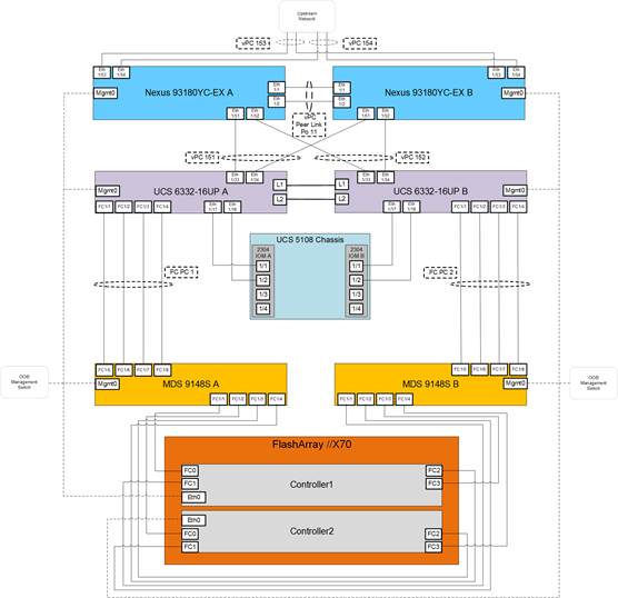
Table 5 through Table 12 provide the connectivity information for the components in the figure above.
Table 5 Cisco Nexus 93180YC-EX-A Cabling Information
| Local Device | Local Port | Connection | Remote Device | Remote Port |
| Cisco Nexus 93180YC-EX A
| Eth1/1 | 10GbE | Cisco Nexus 93180YC-EX B | Eth1/1 |
| Eth1/2 | 10GbE | Cisco Nexus 93180YC-EX B | Eth1/2 | |
| Eth1/51 | 40GbE | Cisco UCS 6332-16UP FI A | Eth 1/33 | |
| Eth1/52 | 40GbE | Cisco UCS 6332-16UP FI B | Eth 1/33 | |
| Eth1/53 | 40GbE or 100GbE | Upstream Network Switch | Any | |
| Eth1/54 | 40GbE or 100GbE | Upstream Network Switch | Any | |
| MGMT0 | GbE | GbE management switch | Any |
Table 6 Cisco Nexus 93180YC-EX-B Cabling Information
| Local Device | Local Port | Connection | Remote Device | Remote Port |
| Cisco Nexus 93180YC-EX B
| Eth1/1 | 10GbE | Cisco Nexus 93180YC-EX A | Eth1/1 |
| Eth1/2 | 10GbE | Cisco Nexus 93180YC-EX A | Eth1/2 | |
| Eth1/51 | 40GbE | Cisco UCS 6332-16UP FI A | Eth 1/34 | |
| Eth1/52 | 40GbE | Cisco UCS 6332-16UP FI B | Eth 1/34 | |
| Eth1/53 | 40GbE or 100GbE | Upstream Network Switch | Any | |
| Eth1/54 | 40GbE or 100GbE | Upstream Network Switch | Any | |
| MGMT0 | GbE | GbE management switch | Any |
![]() The ports Eth1/49-1/54 of the 93180YC-EX switches are ALE (Application Leaf Engine) uplink ports and do not support auto-negotiation. Devices connecting to these ports may need to have speed forced to 40GbE in interfaces on both sides. For the connections shown above going to the 6332-16UP FIs, BiDi (QSFP-40G-SR-BD) transceivers were used between the 93180YC-EX switches and the Fabric Interconnects to establish the 40Gb connection.
The ports Eth1/49-1/54 of the 93180YC-EX switches are ALE (Application Leaf Engine) uplink ports and do not support auto-negotiation. Devices connecting to these ports may need to have speed forced to 40GbE in interfaces on both sides. For the connections shown above going to the 6332-16UP FIs, BiDi (QSFP-40G-SR-BD) transceivers were used between the 93180YC-EX switches and the Fabric Interconnects to establish the 40Gb connection.
Table 7 Cisco UCS 6332-16UP FI A Cabling Information
| Local Device | Local Port | Connection | Remote Device | Remote Port |
| Cisco UCS 6332-16UP FI A
| FC 1/1 | 16Gb FC | MDS 9148S A | FC 1/5 |
| FC 1/2 | 16Gb FC | MDS 9148S A | FC 1/6 | |
| FC 1/3 | 16Gb FC | MDS 9148S A | FC 1/7 | |
| FC 1/4 | 16Gb FC | MDS 9148S A | FC 1/8 | |
| Eth1/17 | 40GbE | Cisco UCS Chassis 1 2304 FEX A | IOM 1/1 | |
| Eth1/18 | 40GbE | Cisco UCS Chassis 1 2304 FEX A | IOM 1/2 | |
| Eth1/33 | 40GbE | Cisco Nexus 93180YC-EX A | Eth1/51 | |
| Eth1/34 | 40GbE | Cisco Nexus 93180YC-EX B | Eth1/51 | |
| MGMT0 | GbE | GbE management switch | Any | |
| L1 | GbE | Cisco UCS 6332-16UP FI B | L1 | |
| L2 | GbE | Cisco UCS 6332-16UP FI B | L2 |
Table 8 Cisco UCS 6332-16UP FI B Cabling Information
| Local Device | Local Port | Connection | Remote Device | Remote Port |
| Cisco UCS 6332-16UP FI B
| FC 1/1 | 16Gb FC | MDS 9148S B | FC 1/5 |
| FC 1/2 | 16Gb FC | MDS 9148S B | FC 1/6 | |
| FC 1/3 | 16Gb FC | MDS 9148S B | FC 1/7 | |
| FC 1/4 | 16Gb FC | MDS 9148S B | FC 1/8 | |
| Eth1/17 | 40GbE | Cisco UCS Chassis 1 2304 FEX B | IOM 1/1 | |
| Eth1/18 | 40GbE | Cisco UCS Chassis 1 2304 FEX B | IOM 1/2 | |
| Eth1/33 | 40GbE | Cisco Nexus 93180YC-EX A | Eth1/52 | |
| Eth1/34 | 40GbE | Cisco Nexus 93180YC-EX B | Eth1/52 | |
| MGMT0 | GbE | GbE management switch | Any | |
| L1 | GbE | Cisco UCS 6332-16UP FI B | L1 | |
| L2 | GbE | Cisco UCS 6332-16UP FI B | L2 |
Table 9 Cisco MDS 9148S A Cabling Information
| Local Device | Local Port | Connection | Remote Device | Remote Port |
| Cisco MDS 9148S A
| FC 1/1 | 16Gb FC | FlashArray//X70 Controller 1 | FC0 |
| FC 1/2 | 16Gb FC | FlashArray//X70 Controller 2 | FC0 | |
| FC 1/3 | 16Gb FC | FlashArray//X70 Controller 1 | FC2 | |
| FC 1/4 | 16Gb FC | FlashArray//X70 Controller 2 | FC2 | |
| FC 1/5 | 16Gb FC | Cisco UCS 6332-16UP FI A | FC 1/1 | |
| FC 1/6 | 16Gb FC | Cisco UCS 6332-16UP FI A | FC 1/2 | |
| FC 1/7 | 16Gb FC | Cisco UCS 6332-16UP FI A | FC 1/3 | |
| FC 1/8 | 16Gb FC | Cisco UCS 6332-16UP FI A | FC 1/4 | |
| MGMT0 | GbE | GbE management switch | Any |
Table 10 Cisco MDS 9148S B Cabling Information
| Local Device | Local Port | Connection | Remote Device | Remote Port |
| Cisco MDS 9148S B
| FC 1/1 | 16Gb FC | FlashArray//X70 Controller 1 | FC1 |
| FC 1/2 | 16Gb FC | FlashArray//X70 Controller 2 | FC1 | |
| FC 1/3 | 16Gb FC | FlashArray//X70 Controller 1 | FC3 | |
| FC 1/4 | 16Gb FC | FlashArray//X70 Controller 2 | FC3 | |
| FC 1/5 | 16Gb FC | Cisco UCS 6332-16UP FI B | FC 1/1 | |
| FC 1/6 | 16Gb FC | Cisco UCS 6332-16UP FI B | FC 1/2 | |
| FC 1/7 | 16Gb FC | Cisco UCS 6332-16UP FI B | FC 1/3 | |
| FC 1/8 | 16Gb FC | Cisco UCS 6332-16UP FI B | FC 1/4 | |
| MGMT0 | GbE | GbE management switch | Any |
Table 11 Pure Storage FlashArray//X70 Controller 1 Cabling Information
| Local Device | Local Port | Connection | Remote Device | Remote Port |
| FlashArray//X70 Controller 1
| FC0 | 16Gb FC | Cisco MDS 9148S A | FC 1/1 |
| FC1 | 16Gb FC | Cisco MDS 9148S B | FC 1/1 | |
| FC2 | 16Gb FC | Cisco MDS 9148S A | FC 1/3 | |
| FC3 | 16Gb FC | Cisco MDS 9148S B | FC 1/3 | |
| Eth0 | GbE | GbE management switch | Any |
Table 12 Pure Storage FlashArray//X70 Controller 2 Cabling Information
| Local Device | Local Port | Connection | Remote Device | Remote Port |
| FlashArray//X70 Controller 2 | FC0 | 16Gb FC | Cisco MDS 9148S A | FC 1/2 |
| FC1 | 16Gb FC | Cisco MDS 9148S B | FC 1/2 | |
| FC2 | 16Gb FC | Cisco MDS 9148S A | FC 1/4 | |
| FC3 | 16Gb FC | Cisco MDS 9148S B | FC 1/4 | |
| Eth0 | GbE | GbE management switch | Any |
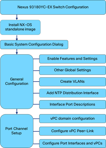
Figure 3 Cisco Nexus Configuration Workflow
Physical Connectivity
Physical cabling should be completed by following the diagram and table references in the previous section referenced as FlashStack Cabling.
FlashStack Nexus Switch Configuration
The following procedures describe how to configure the Cisco Nexus switches for use in a base FlashStack environment. This procedure assumes the use of Nexus 93180YC-EX switches running 7.0(3)I5(2). Configuration on a differing model of Nexus 9000 series switch should be comparable, but may differ slightly with model and changes in NX-OS release. The Cisco Nexus 93180YC-EX switch and NX-OS release were used in validation of this FlashStack solution, so the steps provided will reflect this model and release.
![]() The following procedure includes setup of NTP distribution on the In-Band Management VLAN. The interface-vlan feature and ntp commands are used to set this up. This procedure also assumes the default VRF will be used to route the In-Band Management VLAN.
The following procedure includes setup of NTP distribution on the In-Band Management VLAN. The interface-vlan feature and ntp commands are used to set this up. This procedure also assumes the default VRF will be used to route the In-Band Management VLAN.
Setting the NX-OS image on the Switch
The Cisco Nexus 93180YC-EX switch ships with the Application Centric Infrastructure (ACI) and will need to be reinstalled with NX-OS standalone release specified in this document. The NX-OS standalone software can be downloaded from software.cisco.com. With the image downloaded, it can be transferred to the switches via a USB or SCP from the loader prompt.
For an SCP transfer, the image will need to be accessible from a host reachable by the management interface connected to the switch. Login as admin and configure an available IP for the switch if it is not already on the network. Copy the image over from the server it has been placed on and reload the switch.
(none)#
(none)# ifconfig eth0 inet <<var_nexus_A_mgmt_ip>> netmask <<var_oob_mgmt_mask>>
(none)# scp localadmin@192.168.164.155:/tmp/nxos.7.0.3.I5.2.bin /bootflash
(none)# reload
This command will reload the chassis, Proceed (y/n)? [n]: y
During the reload, press Ctrl-C to interrupt the boot process and enter the loader prompt. From the loader prompt, boot the image copied over.
loader >
loader > boot nxos.7.0.3.I5.2.bin
Booting nxos.7.0.3.I5.2.bin
Trying diskboot
....
Cisco Nexus Basic System Configuration Dialog
Set up the initial configuration for the Cisco Nexus A switch on <<var_nexus_A_hostname>>, by walking through the following dialogue steps:
Abort Auto Provisioning and continue with normal setup ?(yes/no)[n]: y
---- System Admin Account Setup ----
Do you want to enforce secure password standard (yes/no) [y]: <Enter>
Enter the password for "admin": ********
Confirm the password for "admin": ********
---- Basic System Configuration Dialog VDC: 1 ----
This setup utility will guide you through the basic configuration of
the system. Setup configures only enough connectivity for management
of the system.
Please register Cisco Nexus9000 Family devices promptly with your
supplier. Failure to register may affect response times for initial
service calls. Nexus9000 devices must be registered to receive
entitled support services.
Press Enter at anytime to skip a dialog. Use ctrl-c at anytime
to skip the remaining dialogs.
Would you like to enter the basic configuration dialog (yes/no): yes
Create another login account (yes/no) [n]: <Enter>
Configure read-only SNMP community string (yes/no) [n]: <Enter>
Configure read-write SNMP community string (yes/no) [n]: <Enter>
Enter the switch name : <<var_nexus_A_hostname>>
Continue with Out-of-band (mgmt0) management configuration? (yes/no) [y]: <Enter>
Mgmt0 IPv4 address : <<var_nexus_A_mgmt_ip>>
Mgmt0 IPv4 netmask : <<var_oob_mgmt_mask>>
Configure the default gateway? (yes/no) [y]: <Enter>
IPv4 address of the default gateway : <<var_oob_gateway>>
Configure advanced IP options? (yes/no) [n]: <Enter>
Enable the telnet service? (yes/no) [n]: <Enter>
Enable the ssh service? (yes/no) [y]: <Enter>
Type of ssh key you would like to generate (dsa/rsa) [rsa]: <Enter>
Number of rsa key bits <1024-2048> [1024]: <Enter>
Configure the ntp server? (yes/no) [n]: y
NTP server IPv4 address : <<var_oob_ntp>>
Configure default interface layer (L3/L2) [L2]: <Enter>
Configure default switchport interface state (shut/noshut) [noshut]: shut
Configure CoPP system profile (strict/moderate/lenient/dense) [strict]: <Enter>
The following configuration will be applied:
password strength-check
switchname b19-93180-1
vrf context management
ip route 0.0.0.0/0 192.168.164.254
exit
no feature telnet
ssh key rsa 1024 force
feature ssh
ntp server 192.168.164.254
system default switchport
system default switchport shutdown
copp profile strict
interface mgmt0
ip address 192.168.164.13 255.255.255.0
no shutdown
Would you like to edit the configuration? (yes/no) [n]: <Enter>
Use this configuration and save it? (yes/no) [y]: <Enter>
Login and set the image if there is an older image present within bootflash.
User Access Verification
b19-93180-1 login: admin
b19-93180-1# configure terminal
Enter configuration commands, one per line. End with CNTL/Z.
b19-93180-1(config)# boot nxos bootflash:nxos.7.0.3.I5.2.bin
Performing image verification and compatibility check, please wait....
b19-93180-1(config)# copy run start
[########################################] 100%
Copy complete.
Set up the initial configuration for the Cisco Nexus B switch on <<var_nexus_B_hostname>>, by running through the same steps followed in the above configuration, making the appropriate substitutions for <<var_nexus_B_hostname>> and <<var_nexus_B_mgmt_ip>>.
Cisco Nexus Switch Configuration
Enable Features and Settings
To enable IP switching features, run the following commands on each Cisco Nexus:
b19-93180-1&2 (config)# feature lacp
b19-93180-1&2 (config)# feature vpc
b19-93180-1&2 (config)# feature interface-vlan
![]() The feature interface-vlan is an optional requirement if configuring an In-Band VLAN interface to redistribute NTP. Layer-3 routing is possible with Nexus switches after setting this feature, but is not covered in this architecture.
The feature interface-vlan is an optional requirement if configuring an In-Band VLAN interface to redistribute NTP. Layer-3 routing is possible with Nexus switches after setting this feature, but is not covered in this architecture.
Additionally, configure spanning tree and save the running configuration to start-up:
b19-93180-1&2 (config)# spanning-tree port type network default
b19-93180-1&2 (config)# spanning-tree port type edge bpduguard default
b19-93180-1&2 (config)# spanning-tree port type edge bpdufilter default
Set Global Configurations
Run the following commands on both switches to set global configurations:
b19-93180-1&2 (config)# port-channel load-balance src-dst l4port
b19-93180-1&2 (config)# ip route 0.0.0.0/0 <<var_ib-mgmt-vlan_gateway>>
b19-93180-1&2 (config)# ntp server <<var_oob_ntp>> use-vrf management
b19-93180-1&2 (config)# ntp master 3
Create VLANs
Run the following commands on both switches to create VLANs:
b19-93180-1&2 (config)# vlan <<var_ib-mgmt_vlan_id>>
b19-93180-1&2 (config-vlan)# name IB-MGMT-VLAN
b19-93180-1&2 (config-vlan)# vlan <<var_native_vlan_id>>
b19-93180-1&2 (config-vlan)# name Native-VLAN
b19-93180-1&2 (config-vlan)# vlan <<var_vmotion_vlan_id>>
b19-93180-1&2 (config-vlan)# name vMotion-VLAN
b19-93180-1&2 (config-vlan)# vlan <<var_application_vlan_id>>
b19-93180-1&2 (config-vlan)# name VM-App1-VLAN
Continue adding VLANs as appropriate to the customer’s environment.
Add Individual Port Descriptions for Troubleshooting
To add individual port descriptions for troubleshooting activity and verification for switch A, enter the following commands from the global configuration mode:
b19-93180-1(config)# interface Vlan115
b19-93180-1(config-if)# description In-Band NTP Redistribution Interface VLAN 115
b19-93180-1(config-if)# interface port-channel 11
b19-93180-1(config-if)# description vPC peer-link
b19-93180-1(config-if)# interface port-channel 151
b19-93180-1(config-if)# description vPC UCS 6332-16UP-1 FI
b19-93180-1(config-if)# interface port-channel 152
b19-93180-1(config-if)# description vPC UCS 6332-16UP-2 FI
b19-93180-1(config-if)# interface port-channel 153
b19-93180-1(config-if)# description vPC Upstream Network Switch A
b19-93180-1(config-if)# interface port-channel 154
b19-93180-1(config-if)# description vPC Upstream Network Switch B
b19-93180-1(config-if)# interface Ethernet1/1
b19-93180-1(config-if)# description vPC peer-link connection to b19-93180-2 Ethernet1/1
b19-93180-1(config-if)# interface Ethernet1/2
b19-93180-1(config-if)# description vPC peer-link connection to b19-93180-2 Ethernet1/2
b19-93180-1(config-if)# interface Ethernet1/51
b19-93180-1(config-if)# description vPC 151 connection to UCS 6332-16UP-1 FI Ethernet1/33
b19-93180-1(config-if)# interface Ethernet1/52
b19-93180-1(config-if)# description vPC 152 connection to UCS 6332-16UP-2 FI Ethernet1/33
b19-93180-1(config-if)# interface Ethernet1/53
b19-93180-1(config-if)# description vPC 153 connection to Upstream Network Switch A
b19-93180-1(config-if)# interface Ethernet1/54
b19-93180-1(config-if)# description vPC 154 connection to Upstream Network Switch B
![]() In these steps, the interface commands for the VLAN interface and Port-Channel interfaces, will create these interfaces if they do not already exist.
In these steps, the interface commands for the VLAN interface and Port-Channel interfaces, will create these interfaces if they do not already exist.
To add individual port descriptions for troubleshooting activity and verification for switch B, enter the following commands from the global configuration mode:
b19-93180-2(config)# interface Vlan115
b19-93180-2(config-if)# description In-Band NTP Redistribution Interface VLAN 115
b19-93180-2(config-if)# interface port-channel 11
b19-93180-2(config-if)# description vPC peer-link
b19-93180-2(config-if)# interface port-channel 151
b19-93180-2(config-if)# description vPC UCS 6332-16UP-1 FI
b19-93180-2(config-if)# interface port-channel 152
b19-93180-2(config-if)# description vPC UCS 6332-16UP-2 FI
b19-93180-2(config-if)# interface port-channel 153
b19-93180-2(config-if)# description vPC Upstream Network Switch A
b19-93180-2(config-if)# interface port-channel 154
b19-93180-2(config-if)# description vPC Upstream Network Switch B
b19-93180-2(config-if)# interface Ethernet1/1
b19-93180-2(config-if)# description vPC peer-link connection to b19-93180-1 Ethernet1/1
b19-93180-2(config-if)# interface Ethernet1/2
b19-93180-2(config-if)# description vPC peer-link connection to b19-93180-1 Ethernet1/2
b19-93180-2(config-if)# interface Ethernet1/51
b19-93180-2(config-if)# description vPC 151 connection to UCS 6332-16UP-1 FI Ethernet1/34
b19-93180-2(config-if)# interface Ethernet1/52
b19-93180-2(config-if)# description vPC 152 connection to UCS 6332-16UP-2 FI Ethernet1/34
b19-93180-2(config-if)# interface Ethernet1/53
b19-93180-2(config-if)# description vPC 153 connection to Upstream Network Switch A
b19-93180-2(config-if)# interface Ethernet1/54
b19-93180-2(config-if)# description vPC 154 connection to Upstream Network Switch B
Add NTP Distribution Interfaces
Optional VLAN interfaces are created on each Nexus switch to redistribute NTP to In-Band networks from their Out of Band network source. For 93180YC-EX A this will be:
b19-93180-1(config)# ntp source <<var_nexus_A_ib_ip>>
b19-93180-1(config)# ntp master 3
b19-93180-1(config)# interface Vlan115
b19-93180-1(config)# ip route 0.0.0.0/0 <<var_ib_gateway_ip>>
b19-93180-1(config-if)# no shutdown
b19-93180-1(config-if)# no ip redirects
b19-93180-1(config-if)# ip address <<var_nexus_A_ib_ip>>/<<var_ib-mgmt_vlan_netmask_length>>
b19-93180-1(config-if)# no ipv6 redirects
For 93180YC-EX B this will be:
b19-93180-2(config)# ntp source <<var_nexus_B_ib_ip>>
b19-93180-2(config)# ntp master 3
b19-93180-2(config)# interface Vlan115
b19-93180-1(config)# ip route 0.0.0.0/0 <<var_ib_gateway_ip>>
b19-93180-2(config-if)# no shutdown
b19-93180-2(config-if)# no ip redirects
b19-93180-2(config-if)# ip address <<var_nexus_A_ib_ip>>/<<var_ib-mgmt_vlan_netmask_length>>
b19-93180-2(config-if)# no ipv6 redirects
Create the vPC Domain
The vPC domain will be assigned a unique number from 1-1000 and will handle the vPC settings specified within the switches. To set the vPC domain configuration on 93180YC-EX A, run the following commands:
b19-93180-1(config)# vpc domain 10
b19-93180-1(config-vpc-domain)# peer-switch
b19-93180-1(config-vpc-domain)# role priority 10
b19-93180-1(config-vpc-domain)# peer-keepalive destination <<var_nexus_B_mgmt_ip>> source <<var_nexus_A_mgmt_ip>>
b19-93180-1(config-vpc-domain)# delay restore 150
b19-93180-1(config-vpc-domain)# peer-gateway
b19-93180-1(config-vpc-domain)# auto-recovery
b19-93180-1(config-vpc-domain)# ip arp synchronize
On the 93180YC-EX B switch run these slightly differing commands, noting that role priority and peer-keepalive commands will differ from what was previously set:
b19-93180-2(config)# vpc domain 10
b19-93180-2(config-vpc-domain)# peer-switch
b19-93180-2(config-vpc-domain)# role priority 20
b19-93180-2(config-vpc-domain)# peer-keepalive destination <<var_nexus_A_mgmt_ip>> source <<var_nexus_B_mgmt_ip>>
b19-93180-2(config-vpc-domain)# delay restore 150
b19-93180-2(config-vpc-domain)# peer-gateway
b19-93180-2(config-vpc-domain)# auto-recovery
b19-93180-2(config-vpc-domain)# ip arp synchronize
Configure Port Channel Member Interfaces
On each switch, configure the Port Channel member interfaces that will be part of the vPC Peer Link and configure the vPC Peer Link:
b19-93180-1&2 (config)# int eth 1/1-2
b19-93180-1&2 (config-if-range)# channel-group 11 mode active
b19-93180-1&2 (config-if-range)# no shut
b19-93180-1&2 (config-if-range)# int port-channel 11
b19-93180-1&2 (config-if)# switchport mode trunk
b19-93180-1&2 (config-if)# switchport trunk native vlan 2
b19-93180-1&2 (config-if)# switchport trunk allowed vlan 115,200-203
b19-93180-1&2 (config-if)# vpc peer-link
Configure Virtual Port Channels
On each switch, configure the Port Channel member interfaces and the vPC Port Channels to the Cisco UCS Fabric Interconnect and the upstream network switches:
Nexus Connection vPC to UCS Fabric A
b19-93180-1&2 (config-if)# int ethernet 1/51
b19-93180-1&2 (config-if)# channel-group 151 mode active
b19-93180-1&2 (config-if)# no shut
b19-93180-1&2 (config-if)# int port-channel 151
b19-93180-1&2 (config-if)# switchport mode trunk
b19-93180-1&2 (config-if)# switchport trunk native vlan 2
b19-93180-1&2 (config-if)# switchport trunk allowed vlan 115,200-203
b19-93180-1&2 (config-if)# spanning-tree port type edge trunk
b19-93180-1&2 (config-if)# mtu 9216
b19-93180-1&2 (config-if)# load-interval counter 3 60
b19-93180-1&2 (config-if)# vpc 151
Nexus Connection vPC to UCS Fabric B
b19-93180-1&2 (config-if)# int ethernet 1/52
b19-93180-1&2 (config-if)# channel-group 152 mode active
b19-93180-1&2 (config-if)# no shut
b19-93180-1&2 (config-if)# int port-channel 152
b19-93180-1&2 (config-if)# switchport mode trunk
b19-93180-1&2 (config-if)# switchport trunk native vlan 2
b19-93180-1&2 (config-if)# switchport trunk allowed vlan 115,200-203
b19-93180-1&2 (config-if)# spanning-tree port type edge trunk
b19-93180-1&2 (config-if)# mtu 9216
b19-93180-1&2 (config-if)# load-interval counter 3 60
b19-93180-1&2 (config-if)# vpc 152
Nexus Connection vPC to Upstream Network Switch A
b19-93180-1&2 (config-if)# interface Ethernet1/53
b19-93180-1&2 (config-if)# channel-group 153 mode active
b19-93180-1&2 (config-if)# no shut
b19-93180-1&2 (config-if)# int port-channel 153
b19-93180-1&2 (config-if)# switchport mode trunk
b19-93180-1&2 (config-if)# switchport trunk native vlan 2
b19-93180-1&2 (config-if)# switchport trunk allowed vlan 115
b19-93180-1&2 (config-if)# vpc 153
Nexus Connection vPC to Upstream Network Switch B
b19-93180-1&2 (config-if)# interface Ethernet1/54
b19-93180-1&2 (config-if)# channel-group 154 mode active
b19-93180-1&2 (config-if)# no shut
b19-93180-1&2 (config-if)# int port-channel 154
b19-93180-1&2 (config-if)# switchport mode trunk
b19-93180-1&2 (config-if)# switchport trunk native vlan 2
b19-93180-1&2 (config-if)# switchport trunk allowed vlan 115
b19-93180-1&2 (config-if)# int port-channel 154
b19-93180-1&2 (config-if)# vpc 154
*** Save all configuration to this point on both Nexus Switches ***
b19-93180-1&2 (config)# copy running-config startup-config
![]() vPC numbers have been chosen to correspond with the module and first port within a Port Channel, so in the example, having a first member of Ethernet 1/54 results in a vPC/Port Channel number of 154. This is optional, but can help in identifying port to Port Channel memberships.
vPC numbers have been chosen to correspond with the module and first port within a Port Channel, so in the example, having a first member of Ethernet 1/54 results in a vPC/Port Channel number of 154. This is optional, but can help in identifying port to Port Channel memberships.
FlashArray Initial Configuration
The following information should be gathered to enable the installation and configuration of the FlashArray. An official representative of Pure Storage will help rack and configure the new installation of the FlashArray.
Table 13 FlashArray Setup Information
| Global Array Settings | |
| Array Name (Hostname for Pure Array): |
|
| Virtual IP Address for Management: |
|
| Physical IP Address for Management on Controller 0 (CT0): |
|
| Physical IP Address for Management on Controller 1 (CT1): |
|
| Netmask: |
|
| Gateway IP Address: |
|
| DNS Server IP Address(es): |
|
| DNS Domain Suffix: (Optional) |
|
| NTP Server IP Address or FQDN: |
|
| Email Relay Server (SMTP Gateway IP address or FQDN): (Optional) |
|
| Email Domain Name: |
|
| Alert Email Recipients Address(es): (Optional) |
|
| HTTP Proxy Server and Port (For Pure1): (Optional) |
|
| Time Zone: |
|
When the FlashArray has completed initial configuration, it is important to configure the Cloud Assist phone-home connection in order to provide the best pro-active support experience possible. Furthermore, this will enable the analytics functionalities provided by Pure1.
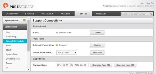
The Support Connectivity sub-view allows you to view and manage the Purity remote assist, phone home, and log features.
The Remote Assist section displays the remote assist status as "Connected" or "Disconnected". By default, remote assist is disconnected. A connected remote assist status means that a remote assist session has been opened, allowing Pure Storage Support to connect to the array. Disconnect the remote assist session to close the session.
The Phone Home section manages the phone home facility. The phone home facility provides a secure direct link between the array and the Pure Storage Technical Support web site. The link is used to transmit log contents and alert messages to the Pure Storage Support team so that when diagnosis or remedial action is required, complete recent history about array performance and significant events is available.
By default, the phone home facility is enabled. If the phone home facility is enabled to send information automatically, Purity transmits log and alert information directly to Pure Storage Support via a secure network connection. Log contents are transmitted hourly and stored at the support web site, enabling detection of array performance and error rate trends. Alerts are reported immediately when they occur so that timely action can be taken.
Phone home logs can also be sent to Pure Storage Technical support on demand, with options including Today's Logs, Yesterday's Logs, or All Log History.
The Support Logs section allows you to download the Purity log contents of the specified controller to the current administrative workstation. Purity continuously logs a variety of array activities, including performance summaries, hardware and operating status reports, and administrative actions.
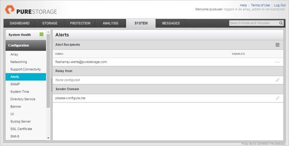
Adding an Alert Recipient
The Alerts sub-view is used to manage the list of addresses to which Purity delivers alert notifications, and the attributes of alert message delivery. You can designate up to 19 alert recipients. The Alert Recipients section displays a list of email addresses that are designated to receive Purity alert messages. Up to 20 alert recipients can be designated. The list includes the built-in flasharray-alerts@purestorage.com address, which cannot be deleted.
The Relay Host section displays the hostname or IP address of an SMTP relay host, if one is configured for the array. If you specify a relay host, Purity routes the email messages via the relay (mail forwarding) address rather than sending them directly to the alert recipient addresses.
In the Sender Domain section, the sender domain determines how Purity logs are parsed and treated by Pure Storage Support and Escalations. By default, the sender domain is set to the domain name please-configure.me.
It is crucial that you set the sender domain to the correct domain name. If the array is not a Pure Storage test array, set the sender domain to the actual customer domain name. For example, mycompany.com.
The email address that Purity uses to send alert messages includes the sender domain name and is comprised of the following components:
<Array_Name>-<Controller_Name>@<Sender_Domain_Name>.com
To add an alert recipient, complete the following steps:
1. Select System > Configuration > Alerts.
2. In the Alert Recipients section, click the menu icon and select Add Alert Recipient. The Create Alert User dialog box appears.
3. In the email field, enter the email address of the alert recipient.
4. Click Save.
Configuring the Domain Name System (DNS) Server IP Addresses
To configure the DNS server IP addresses, complete the following steps:
1. Select System > Configuration > Networking.
2. In the DNS section, hover over the domain name and click the pencil icon. The Edit DNS dialog box appears.
3. Complete the following fields:
a. Domain: Specify the domain suffix to be appended by the array when doing DNS lookups.
b. DNS#: Specify up to three DNS server IP addresses for Purity to use to resolve hostnames to IP addresses. Enter one IP address in each DNS# field. Purity queries the DNS servers in the order that the IP addresses are listed.
4. Click Save.
Directory Service Sub-View
The Directory Service sub-view manages the integration of FlashArrays with an existing directory service. When the Directory Service sub-view is configured and enabled, the FlashArray leverages a directory service to perform user account and permission level searches. Configuring directory services is OPTIONAL.
The FlashArray is delivered with a single local user, named pureuser, with array-wide (Array Admin) permissions.
To support multiple FlashArray users, integrate the array with a directory service, such as Microsoft Active Directory or OpenLDAP.
Role-based access control is achieved by configuring groups in the directory that correspond to the following permission groups (roles) on the array:
· Read Only Group. Read Only users have read-only privileges to run commands that convey the state of the array. Read Only uses cannot alter the state of the array.
· Storage Admin Group. Storage Admin users have all the privileges of Read Only users, plus the ability to run commands related to storage operations, such as administering volumes, hosts, and host groups. Storage Admin users cannot perform operations that deal with global and system configurations.
· Array Admin Group. Array Admin users have all the privileges of Storage Admin users, plus the ability to perform array-wide changes. In other words, Array Admin users can perform all FlashArray operations.
When a user connects to the FlashArray with a username other than pureuser, the array confirms the user's identity from the directory service. The response from the directory service includes the user's group, which Purity maps to a role on the array, granting access accordingly.
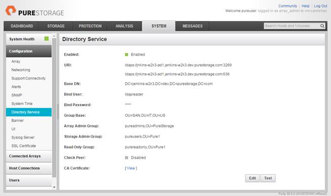
To configure the directory service settings, complete the following steps:
1. Select System > Configuration > Directory Service.
2. Configure the Directory Service fields:
a. Enabled: Select the check box to leverage the directory service to perform user account and permission level searches.
b. URI: Enter the comma-separated list of up to 30 URIs of the directory servers. The URI must include a URL scheme (ldap, or ldaps for LDAP over SSL), the hostname, and the domain. You can optionally specify a port. For example, ldap://ad.company.com configures the directory service with the hostname "ad" in the domain "company.com" while specifying the unencrypted LDAP protocol.
c. Base DN: Enter the base distinguished name (DN) of the directory service. The Base DN is built from the domain and should consist only of domain components (DCs). For example, for ldap://ad.storage.company.com, the Base DN would be: “DC=storage,DC=company,DC=com”
d. Bind User: Username used to bind to and query the directory. For Active Directory, enter the username - often referred to as sAMAccountName or User Logon Name - of the account that is used to perform directory lookups. The username cannot contain the characters " [ ] : ; | = + * ? < > / \, and cannot exceed 20 characters in length. For OpenLDAP, enter the full DN of the user. For example, "CN=John,OU=Users,DC=example,DC=com".
e. Bind Password: Enter the password for the bind user account.
f. Group Base: Enter the organizational unit (OU) to the configured groups in the directory tree. The Group Base consists of OUs that, when combined with the base DN attribute and the configured group CNs, complete the full Distinguished Name of each groups. The group base should specify "OU=" for each OU and multiple OUs should be separated by commas. The order of OUs should get larger in scope from left to right. In the following example, SANManagers contains the sub-organizational unit PureGroups: "OU=PureGroups,OU=SANManagers".
g. Array Admin Group: Common Name (CN) of the directory service group containing administrators with full privileges to manage the FlashArray. Array Admin Group administrators have the same privileges as pureuser. The name should be the Common Name of the group without the "CN=" specifier. If the configured groups are not in the same OU, also specify the OU. For example, "pureadmins,OU=PureStorage", where pureadmins is the common name of the directory service group.
h. Storage Admin Group: Common Name (CN) of the configured directory service group containing administrators with storage related privileges on the FlashArray. The name should be the Common Name of the group without the "CN=" specifier. If the configured groups are not in the same OU, also specify the OU. For example, "pureusers,OU=PureStorage", where pureusers is the common name of the directory service group.
i. Read Only Group: Common Name (CN) of the configured directory service group containing users with read-only privileges on the FlashArray. The name should be the Common Name of the group without the "CN=" specifier. If the configured groups are not in the same OU, also specify the OU. For example, "purereadonly,OU=PureStorage", where purereadonly is the common name of the directory service group.
j. Check Peer: Select the check box to validate the authenticity of the directory servers using the CA Certificate. If you enable Check Peer, you must provide a CA Certificate.
k. CA Certificate: Enter the certificate of the issuing certificate authority. Only one certificate can be configured at a time, so the same certificate authority should be the issuer of all directory server certificates. The certificate must be PEM formatted (Base64 encoded) and include the "-----BEGIN CERTIFICATE-----" and "-----END CERTIFICATE-----" lines. The certificate cannot exceed 3000 characters in total length.
3. Click Save.
4. Click Test to test the configuration settings. The LDAP Test Results pop-up window appears. Green squares represent successful checks. Red squares represent failed checks.
SSL Certificate Sub-View
Purity creates a self-signed certificate and private key when you start the system for the first time. The SSL Certificate sub-view allows you to view and change certificate attributes, create a new self-signed certificate, construct certificate signing requests, import certificates and private keys, and export certificates.
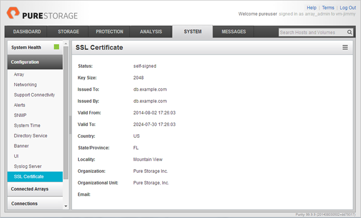
Creating a self-signed certificate replaces the current certificate. When you create a self-signed certificate, include any attribute changes, specify the validity period of the new certificate, and optionally generate a new private key.
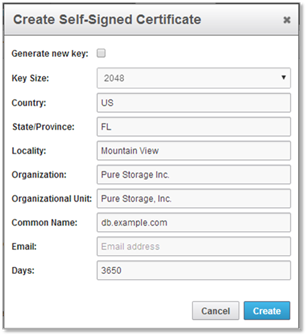
When you create the self-signed certificate, you can generate a private key and specify a different key size. If you do not generate a private key, the new certificate uses the existing key.
You can change the validity period of the new self-signed certificate. By default, self-signed certificates are valid for 3650 days.
CA-Signed Certificate
Certificate authorities (CA) are third party entities outside the organization that issue certificates. To obtain a CA certificate, you must first construct a certificate signing request (CSR) on the array.
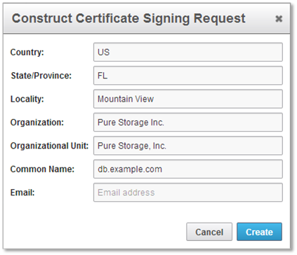
The CSR represents a block of encrypted data specific to your organization. You can change the certificate attributes when you construct the CSR; otherwise, Purity will reuse the attributes of the current certificate (self-signed or imported) to construct the new one. Note that the certificate attribute changes will only be visible after you import the signed certificate from the CA.
Send the CSR to a certificate authority for signing. The certificate authority returns the SSL certificate for you to import. Verify that the signed certificate is PEM formatted (Base64 encoded), includes the "-----BEGIN CERTIFICATE-----" and "-----END CERTIFICATE-----" lines, and does not exceed 3000 characters in total length. When you import the certificate, also import the intermediate certificate if it is not bundled with the CA certificate.
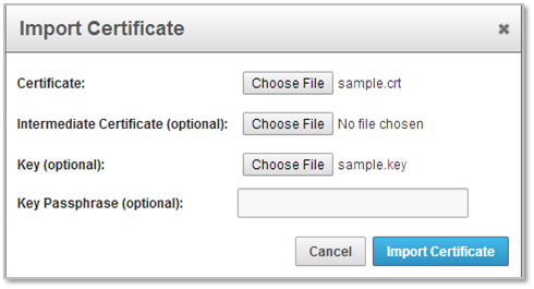
If the certificate is signed with the CSR that was constructed on the current array and you did not change the private key, you do not need to import the key. However, if the CSR was not constructed on the current array or if the private key has changed since you constructed the CSR, you must import the private key. If the private key is encrypted, also specify the passphrase.
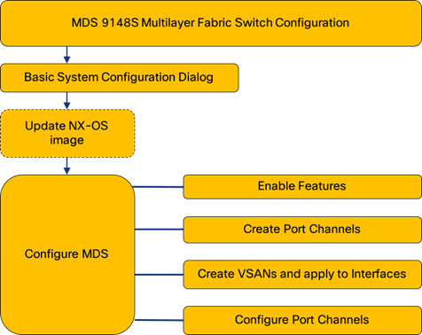
This section provides detailed instructions for the configuration of the Cisco MDS 9148S Multilayer Fabric Switches used in this FlashStack solution. Some changes may be appropriate for a customer’s environment, but care should be taken when stepping outside of these instructions as it may lead to an improper configuration.
Figure 4 Cisco 9148S Multilayer Fabric Switch Configuration Workflow
Physical Connectivity
Physical cabling should be completed by following the diagram and table references in the previous section referenced as FlashStack Cabling.
MDS Basic System Configuration Dialog
Set up the initial configuration for the Cisco MDS A switch on <<var_mds_A_hostname>>, by walking through the following dialogue steps:
Abort Auto Provisioning and continue with normal setup ?(yes/no)[n]: y
---- System Admin Account Setup ----
Do you want to enforce secure password standard (yes/no) [y]:
Enter the password for "admin":
Confirm the password for "admin":
---- Basic System Configuration Dialog ----
This setup utility will guide you through the basic configuration of
the system. Setup configures only enough connectivity for management
of the system.
Please register Cisco MDS 9000 Family devices promptly with your
supplier. Failure to register may affect response times for initial
service calls. MDS devices must be registered to receive entitled
support services.
Press Enter at anytime to skip a dialog. Use ctrl-c at anytime
to skip the remaining dialogs.
Would you like to enter the basic configuration dialog (yes/no): yes
Create another login account (yes/no) [n]:
Configure read-only SNMP community string (yes/no) [n]:
Configure read-write SNMP community string (yes/no) [n]:
Enter the switch name : <<var_mds_A_hostname>>
Continue with Out-of-band (mgmt0) management configuration? (yes/no) [y]:
Mgmt0 IPv4 address : <<var_mds_A_mgmt_ip>>
Mgmt0 IPv4 netmask : <<var_oob_mgmt_mask>>
Configure the default gateway? (yes/no) [y]:
IPv4 address of the default gateway : <<var_oob_gateway>>
Configure advanced IP options? (yes/no) [n]:
Enable the ssh service? (yes/no) [y]:
Type of ssh key you would like to generate (dsa/rsa) [rsa]:
Number of rsa key bits <1024-2048> [1024]: 2048
Enable the telnet service? (yes/no) [n]:
Configure congestion/no_credit drop for fc interfaces? (yes/no) [y]:
Enter the type of drop to configure congestion/no_credit drop? (con/no) [c]:
Enter milliseconds in multiples of 10 for congestion-drop for port mode F
in range (<100-500>/default), where default is 500. [d]:
Congestion-drop for port mode E must be greater than or equal to
Congestion-drop for port mode F. Hence, Congestion drop for port
mode E will be set as default.
Enable the http-server? (yes/no) [y]:
Configure clock? (yes/no) [n]:
Configure timezone? (yes/no) [n]: y
Enter timezone config [PST/MST/CST/EST] :EST
Enter Hrs offset from UTC [-23:+23] :-5
Enter Minutes offset from UTC [0-59] :0
Configure summertime? (yes/no) [n]:
Configure the ntp server? (yes/no) [n]: y
NTP server IPv4 address : 192.168.164.254
Configure default switchport interface state (shut/noshut) [shut]:
Configure default switchport trunk mode (on/off/auto) [on]:
Configure default switchport port mode F (yes/no) [n]:
Configure default zone policy (permit/deny) [deny]:
Enable full zoneset distribution? (yes/no) [n]:
Configure default zone mode (basic/enhanced) [basic]:
The following configuration will be applied:
password strength-check
switchname mds-9148s-a
interface mgmt0
ip address 192.168.164.15 255.255.255.0
no shutdown
ip default-gateway 192.168.164.254
ssh key rsa 2048 force
feature ssh
no feature telnet
system timeout congestion-drop default mode F
system timeout congestion-drop default mode E
feature http-server
clock timezone EST -5 0
ntp server 192.168.164.254
system default switchport shutdown
system default switchport trunk mode on
no system default zone default-zone permit
no system default zone distribute full
no system default zone mode enhanced
Would you like to edit the configuration? (yes/no) [n]:
Use this configuration and save it? (yes/no) [y]:
Set up the initial configuration for the Cisco MDS B switch on <<var_mds_B_hostname>>, by running through the same steps followed in the configuration, making the appropriate substitutions for <<var_mds_B_hostname>> and <<var_mds_B_mgmt_ip>>.
Upgrade Cisco MDS NX-OS release 6.2(21)
This document assumes you are using Cisco NX-OS 6.2(21). To upgrade the Cisco MDS 9148S software to version 6.2(21), refer to the Cisco MDS 9000 NX-OS Software Upgrade and Downgrade Guide, Release 6.2(x).
MDS Configuration
Set MDS Features
On each MDS 9148S switch, enable these features:
mds-9148s-a&b(config)# feature npiv
mds-9148s-a&b(config)# feature fport-channel-trunk
Create Port Channels and VSANs
On MDS 9148S A create a Port Channel that will uplink to the Cisco UCS Fabric Interconnect:
mds-9148s-a(config)# interface port-channel 1
On MDS 9148S B create a Port Channel that will uplink to the Cisco UCS Fabric Interconnect:
mds-9148s-b(config)# interface port-channel 2
On MDS 9148S A create the VSAN that will be used for connectivity to the Cisco UCS Fabric Interconnect and the Pure Storage FlashArray. Assign this VSAN to the interfaces that will connect to the Pure Storage FlashArray, as well as the interfaces and the Port Channel they create that are connected to the Cisco UCS Fabric Interconnect:
mds-9148s-a(config)# vsan database
mds-9148s-a(config-vsan-db)# vsan <<var_vsan_a_id>>
mds-9148s-a(config-vsan-db)# vsan <<var_vsan_a_id>> name Fabric-A
mds-9148s-a(config-vsan-db)# exit
mds-9148s-a(config)# zone smart-zoning enable vsan <<var_vsan_a_id>>
mds-9148s-a(config)# vsan database
mds-9148s-a(config-vsan-db)# vsan <<var_vsan_a_id>> interface fc1/1-4
mds-9148s-a(config-vsan-db)# vsan <<var_vsan_a_id>> interface po1
mds-9148s-a(config-vsan-db)# exit
mds-9148s-a(config)# int fc1/1-4
mds-9148s-a(config-if)# no shut
mds-9148s-a(config-if)# exit
Repeat these commands on MDS 9148S B using the Fabric B appropriate VSAN ID:
mds-9148s-b(config)# vsan database
mds-9148s-b(config-vsan-db)# vsan <<var_vsan_b_id>>
mds-9148s-b(config-vsan-db)# vsan <<var_vsan_b_id>> name Fabric-B
mds-9148s-b(config-vsan-db)# exit
mds-9148s-b(config)# zone smart-zoning enable vsan <<var_vsan_b_id>>
mds-9148s-b(config)# vsan database
mds-9148s-b(config-vsan-db)# vsan <<var_vsan_b_id>> interface fc1/1-4
mds-9148s-b(config-vsan-db)# vsan <<var_vsan_b_id>> interface po2
mds-9148s-b(config-vsan-db)# exit
mds-9148s-b(config)# int fc1/1-4
mds-9148s-b(config-if)# no shut
mds-9148s-b(config-if)# exit
Configure the MDS 9148S A Port Channel and add the interfaces connecting into the Cisco UCS Fabric Interconnect into it:
mds-9148s-a(config)# interface port-channel 1
mds-9148s-a(config-if)# channel mode active
mds-9148s-a(config-if)# switchport rate-mode dedicated
mds-9148s-a(config-if)# interface fc1/5-8
mds-9148s-a(config-if)# port-license acquire
mds-9148s-a(config-if)# channel-group 1 force
mds-9148s-a(config-if)# no shutdown
Repeat these commands on MDS 9148S B using the Fabric B appropriate Port Channel:
mds-9148s-b(config)# interface port-channel 2
mds-9148s-b(config-if)# channel mode active
mds-9148s-b(config-if)# switchport rate-mode dedicated
mds-9148s-b(config-if)# interface fc1/5-8
mds-9148s-b(config-if)# port-license acquire
mds-9148s-b(config-if)# channel-group 2 force
mds-9148s-b(config-if)# no shutdown
*** Save all configuration to this point on both MDS Switches ***
mds-9148s-a&b (config-if)# copy running-config startup-config
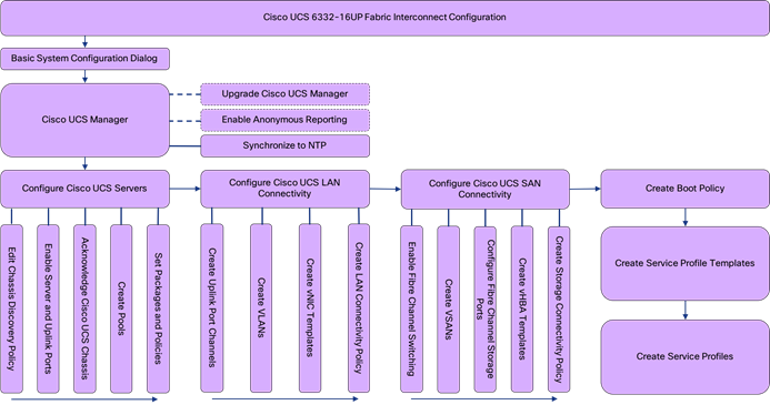
This section provides detailed instructions for the configuration of the Cisco UCS 6332-16UP Fabric Interconnects used in this FlashStack solution. As with the Nexus and MDS Switches covered beforehand, some changes may be appropriate for a customer’s environment, but care should be taken when stepping outside of these instructions as it may lead to an improper configuration.
Figure 5 Cisco UCS Configuration Workflow
Physical Connectivity
Physical cabling should be completed by following the diagram and table references in the previous section referenced as FlashStack Cabling.
Cisco UCS Base Configuration
The initial configuration dialogue for the Cisco UCS 6332-16UP Fabric Interconnects will be provide the primary information to the first fabric interconnect, with the second taking on most settings after joining the cluster.
To start on the configuration of the Fabric Interconnect A, connect to the console of the fabric interconnect and step through the Basic System Configuration Dialogue:
---- Basic System Configuration Dialog ----
This setup utility will guide you through the basic configuration of
the system. Only minimal configuration including IP connectivity to
the Fabric interconnect and its clustering mode is performed through these steps.
Type Ctrl-C at any time to abort configuration and reboot system.
To back track or make modifications to already entered values,
complete input till end of section and answer no when prompted
to apply configuration.
Enter the configuration method. (console/gui) ? console
Enter the setup mode; setup newly or restore from backup. (setup/restore) ? setup
You have chosen to setup a new Fabric interconnect. Continue? (y/n): y
Enforce strong password? (y/n) [y]: <Enter>
Enter the password for "admin": ********
Confirm the password for "admin": ********
Is this Fabric interconnect part of a cluster(select 'no' for standalone)? (yes/no) [n]: y
Enter the switch fabric (A/B) []: A
Enter the system name: <<var_ucs_6332_clustername>>
Physical Switch Mgmt0 IP address : <<var_ucsa_mgmt_ip>>
Physical Switch Mgmt0 IPv4 netmask : <<var_oob_mgmt_mask>>
IPv4 address of the default gateway : <<var_oob_gateway>>
Cluster IPv4 address : <<var_ucs_mgmt_vip>>
Configure the DNS Server IP address? (yes/no) [n]: y
DNS IP address : <<var_nameserver_ntp>>
Configure the default domain name? (yes/no) [n]: y
Default domain name : <<var_dns_domain_name>>
Join centralized management environment (UCS Central)? (yes/no) [n]: <Enter>
Following configurations will be applied:
Switch Fabric=A
System Name=bb08-6332
Enforced Strong Password=yes
Physical Switch Mgmt0 IP Address=192.168.164.51
Physical Switch Mgmt0 IP Netmask=255.255.255.0
Default Gateway=192.168.164.254
Ipv6 value=0
DNS Server=10.1.164.9
Domain Name=earthquakes.cisco.com
Cluster Enabled=yes
Cluster IP Address=192.168.164.50
NOTE: Cluster IP will be configured only after both Fabric Interconnects are initialized.
UCSM will be functional only after peer FI is configured in clustering mode.
Apply and save the configuration (select 'no' if you want to re-enter)? (yes/no): yes
Applying configuration. Please wait.
Configuration file - Ok
Continue the configuration on the console of the Fabric Interconnect B:
Enter the configuration method. (console/gui) [console] ?
Installer has detected the presence of a peer Fabric interconnect. This Fabric interconnect will be added to the cluster. Continue (y/n) ? y
Enter the admin password of the peer Fabric interconnect:
Connecting to peer Fabric interconnect... done
Retrieving config from peer Fabric interconnect... done
Peer Fabric interconnect Mgmt0 IPv4 Address: 192.168.164.51
Peer Fabric interconnect Mgmt0 IPv4 Netmask: 255.255.255.0
Cluster IPv4 address : 192.168.164.50
Peer FI is IPv4 Cluster enabled. Please Provide Local Fabric Interconnect Mgmt0 IPv4 Address
Physical Switch Mgmt0 IP address : 192.168.164.52
Apply and save the configuration (select 'no' if you want to re-enter)? (yes/no): yes
Applying configuration. Please wait.
Cisco UCS Manager Setup
Log in to Cisco UCS Manager
To log in to the Cisco Unified Computing System (UCS) environment and Cisco UCS Manager (UCSM), complete the following steps:
1. Open a web browser and navigate to the Cisco UCS fabric interconnect cluster address.
2. Click the Launch UCS Manager link within the opening page.
3. If prompted to accept security certificates, accept as necessary.
4. When the UCS Manager login is prompted, enter admin as the user name and enter the administrative password.
5. Click Login to log in to Cisco UCS Manager.
Upgrade Cisco UCS Manager Software to Version 3.2(1d)
This document assumes the use of Cisco UCS 3.2(1d). To upgrade the Cisco UCS Manager software and the Cisco UCS Fabric Interconnect software to version 3.2(1d), refer to Cisco UCS Manager Install and Upgrade Guides.
Anonymous Reporting
During the first connection to the Cisco UCS Manager GUI, a pop-up window will appear to allow for the configuration of Anonymous Reporting to Cisco on use to help with future development. To create anonymous reporting, complete the following step:
1. In the Anonymous Reporting window, select whether to send anonymous data to Cisco for improving future products, and provide the appropriate SMTP server gateway information if configuring:
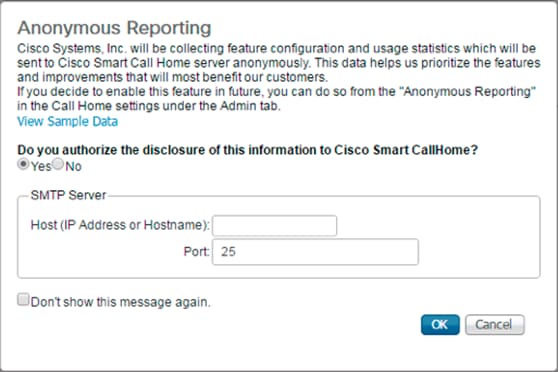
If there is a desire to enable or disable Anonymous Reporting at a later date, it can be found within Cisco UCS Manager under: Admin -> Communication Management -> Call Home, which has a tab on the far right for Anonymous Reporting.
Synchronize Cisco UCS to NTP
To synchronize the Cisco UCS environment to the NTP server, complete the following steps:
1. In Cisco UCS Manager, click the Admin tab in the navigation pane.
2. Select Timezone Management, and click Timezone.
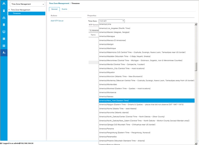
3. In the Properties pane, select the appropriate time zone in the Timezone menu.
4. Click Save Changes, and then click OK.
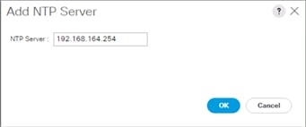
5. Click Add NTP Server.
6. Enter <<var_oob_ntp>> and click OK.
7. Click OK.
Configure Cisco UCS Servers
Edit Chassis Discovery Policy
Setting the discovery policy simplifies the addition of B-Series Cisco UCS chassis. To modify the chassis discovery policy, complete the following steps:
1. In Cisco UCS Manager, click the Equipment tab in the navigation pane and select Policies in the list on the left under the drop-down.
2. Under Global Policies, set the Chassis/FEX Discovery Policy to match the number of uplink ports that are cabled between the chassis or fabric extenders (FEXes) and the fabric interconnects.
3. Set the Link Grouping Preference to Port Channel.
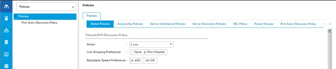
4. Leave other settings alone or change if appropriate to your environment.
5. Click Save Changes.
6. Click OK.
Enable Server and Uplink Ports
To enable server and uplink ports, complete the following steps:
1. In Cisco UCS Manager, click the Equipment tab in the navigation pane.
2. Select Equipment > Fabric Interconnects > Fabric Interconnect A (primary) > Fixed Module.
3. Expand Ethernet Ports.
4. Select the ports that are connected to the chassis, right-click them, and select “Configure as Server Port.”
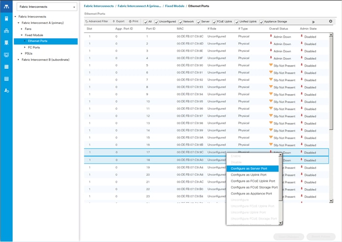
5. Click Yes to confirm server ports and click OK.
6. Verify that the ports connected to the chassis are now configured as server ports.
7. Select ports 39 and 40 that are connected to the Cisco Nexus switches, right-click them, and select Configure as Uplink Port.
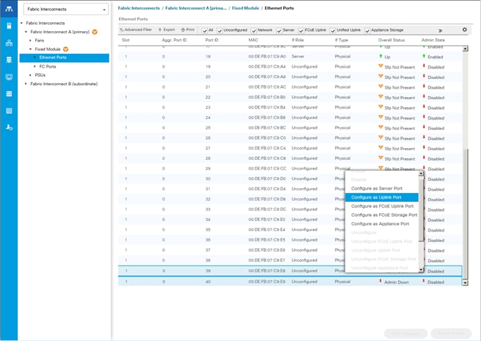
![]() The last 6 ports of the UCS 6332 and UCS 6332-16UP FIs will only work with optical based QSFP transceivers and AOC cables, so they can be better utilized as uplinks to upstream resources that might be optical only.
The last 6 ports of the UCS 6332 and UCS 6332-16UP FIs will only work with optical based QSFP transceivers and AOC cables, so they can be better utilized as uplinks to upstream resources that might be optical only.
8. Click Yes to confirm uplink ports and click OK.
9. Select Equipment > Fabric Interconnects > Fabric Interconnect B (subordinate) > Fixed Module.
10. Expand Ethernet Ports.
11. Select the ports that are connected to the chassis, right-click them and select Configure as Server Port.
12. Click Yes to confirm server ports and click OK.
13. Select ports 39 and 40 that are connected to the Cisco Nexus switches, right-click them, and select Configure as Uplink Port.
14. Click Yes to confirm the uplink ports and click OK.
Acknowledge Cisco UCS Chassis
To acknowledge all Cisco UCS chassis, complete the following steps:
1. In Cisco UCS Manager, click the Equipment tab in the navigation pane.
2. Expand Chassis and select each chassis that is listed.
3. Right-click each chassis and select Acknowledge Chassis.
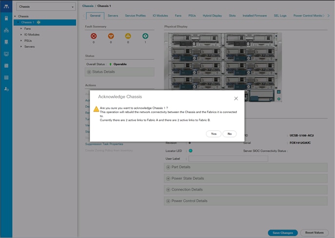
4. Click Yes and then click OK to complete acknowledging the chassis.
5. Click Yes and then click OK to complete acknowledging the chassis.
Create Pools
Create MAC Address Pools
To configure the necessary MAC address pools for the Cisco UCS environment, complete the following steps:
1. In Cisco UCS Manager, click the LAN tab in the navigation pane.
2. Select Pools > root.
![]() In this procedure, two MAC address pools are created, one for each switching fabric.
In this procedure, two MAC address pools are created, one for each switching fabric.
3. Right-click MAC Pools under the root organization.
4. Select Create MAC Pool to create the MAC address pool.
5. Enter MAC_Pool_A as the name of the MAC pool.
6. Optional: Enter a description for the MAC pool.
7. Select Sequential as the option for Assignment Order.
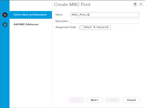
8. Click Next.
9. Click Add.
10. Specify a starting MAC address.
![]() For Cisco UCS deployments, the recommendation is to place 0A in the next-to-last octet of the starting MAC address to identify all of the MAC addresses as fabric A addresses. In our example, we have carried forward the of also embedding the extra building, floor and Cisco UCS domain number information giving us 00:25:B5:91:1A:00 as our first MAC address.
For Cisco UCS deployments, the recommendation is to place 0A in the next-to-last octet of the starting MAC address to identify all of the MAC addresses as fabric A addresses. In our example, we have carried forward the of also embedding the extra building, floor and Cisco UCS domain number information giving us 00:25:B5:91:1A:00 as our first MAC address.
11. Specify a size for the MAC address pool that is sufficient to support the available blade or server resources.
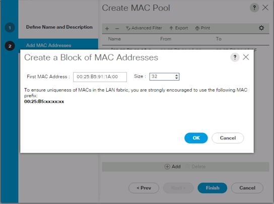
12. Click OK.
13. Click Finish.
14. In the confirmation message, click OK.
15. Right-click MAC Pools under the root organization.
16. Select Create MAC Pool to create the MAC address pool.
17. Enter MAC_Pool_B as the name of the MAC pool.
18. Optional: Enter a description for the MAC pool.
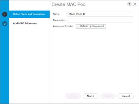
19. Click Next.
20. Click Add.
21. Specify a starting MAC address.
![]() For Cisco UCS deployments, it is recommended to place 0B in the next to last octet of the starting MAC address to identify all the MAC addresses in this pool as fabric B addresses. Once again, we have carried forward in our example of embedding the extra building, floor and Cisco UCS domain number information giving us 00:25:B5:91:1B:00 as our first MAC address.
For Cisco UCS deployments, it is recommended to place 0B in the next to last octet of the starting MAC address to identify all the MAC addresses in this pool as fabric B addresses. Once again, we have carried forward in our example of embedding the extra building, floor and Cisco UCS domain number information giving us 00:25:B5:91:1B:00 as our first MAC address.
22. Specify a size for the MAC address pool that is sufficient to support the available blade or server resources.
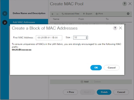
23. Click OK.
24. Click Finish.
25. In the confirmation message, click OK.
Create UUID Suffix Pool
To configure the necessary universally unique identifier (UUID) suffix pool for the Cisco UCS environment, complete the following steps:
1. In Cisco UCS Manager, click the Servers tab in the navigation pane.
2. Select Pools > root.
3. Right-click UUID Suffix Pools.
4. Select Create UUID Suffix Pool.
5. Enter UUID_Pool as the name of the UUID suffix pool.
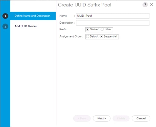
6. Optional: Enter a description for the UUID suffix pool.
7. Keep the prefix at the derived option.
8. Select Sequential for the Assignment Order.
9. Click Next.
10. Click Add to add a block of UUIDs.
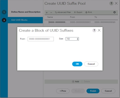
11. Keep the From: field at the default setting.
12. Specify a size for the UUID block that is sufficient to support the available blade or server resources.
13. Click OK.
14. Click Finish.
15. Click OK.
Create Server Pool
To configure the necessary server pool for the Cisco UCS environment, complete the following steps:
![]() Consider creating unique server pools to achieve the granularity that is required in your environment.
Consider creating unique server pools to achieve the granularity that is required in your environment.
1. In Cisco UCS Manager, click the Servers tab in the navigation pane.
2. Select Pools > root.
3. Right-click Server Pools.
4. Select Create Server Pool.
5. Enter Infra_Pool as the name of the server pool.
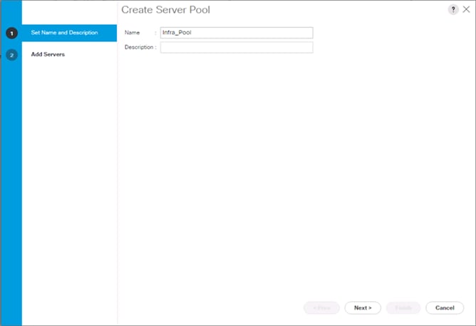
6. Optional: Enter a description for the server pool.
7. Click Next.
8. Select two (or more) servers to be used for the VMware management cluster and click >> to add them to the Infra_Pool server pool.
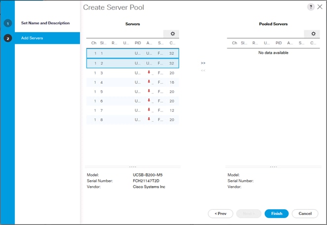
9. Click Finish.
10. Click OK.
Add a Block of IP Addresses for KVM Access
To create a block of IP addresses for in band server Keyboard, Video, Mouse (KVM) access in the Cisco UCS environment, complete the following steps:
1. In Cisco UCS Manager, click the LAN tab in the navigation pane.
2. Select Pools > root > IP Pools.
3. Right-click IP Pool ext-mgmt and select Create Block of IPv4 Addresses.
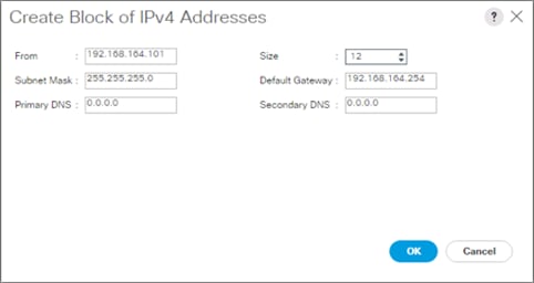
4. Enter the starting IP address of the block and the number of IP addresses required, and the subnet and gateway information.
5. Click OK to create the block of IPs.
6. Click OK.
Create a WWNN Pool
To configure the necessary WWNN pool for the Cisco UCS environment, complete the following steps on Cisco UCS Manager:
1. Select the SAN tab on the left.
2. Select Pools > root.
3. Right-click WWNN Pools under the root organization.
4. Select Create WWNN Pool to create the WWNN pool.
5. Enter WWNN_Pool for the name of the WWNN pool.
6. Optional: Enter a description for the WWNN pool.
7. Select Sequential for Assignment Order.
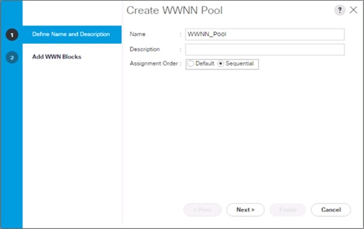
8. Click Next.
9. Click Add.
10. Modify the From field as necessary for the UCS Environment.
![]() Modifications of the WWN block, as well as the WWPN and MAC Addresses, can convey identifying information for the Cisco UCS domain. Within the From field in our example, the 6th octet was changed from 00 to 01 to represent as identifying information for this being our first Cisco UCS domain.
Modifications of the WWN block, as well as the WWPN and MAC Addresses, can convey identifying information for the Cisco UCS domain. Within the From field in our example, the 6th octet was changed from 00 to 01 to represent as identifying information for this being our first Cisco UCS domain.
![]() Also, when having multiple Cisco UCS domains sitting in adjacency, it is important that these blocks, the WWNN, WWPN, and MAC hold differing values between each set.
Also, when having multiple Cisco UCS domains sitting in adjacency, it is important that these blocks, the WWNN, WWPN, and MAC hold differing values between each set.
11. Specify a size of the WWNN block sufficient to support the available server resources.
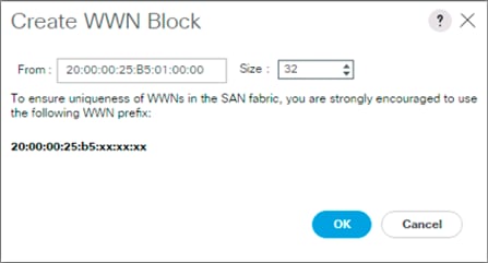
12. Click OK.
13. Click Finish to create the WWNN Pool.
14. Click OK.
Create WWPN Pools
To configure the necessary WWPN pools for the Cisco UCS environment, complete the following steps:
1. In Cisco UCS Manager, click the SAN tab in the navigation pane.
2. Select Pools > root.
3. In this procedure, two WWPN pools are created, one for each switching fabric.
4. Right-click WWPN Pools under the root organization.
5. Select Create WWPN Pool to create the WWPN pool.
6. Enter WWPN_Pool_A as the name of the WWPN pool.
7. Optional: Enter a description for the WWPN pool.
8. Select Sequential for Assignment Order.
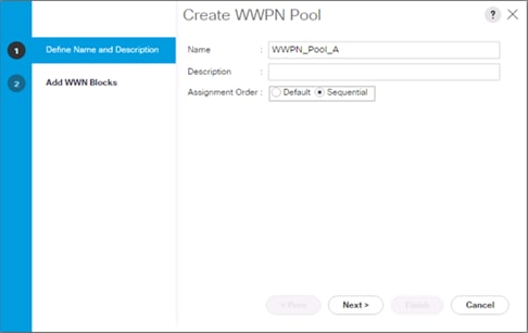
9. Click Next.
10. Click Add.
11. Specify a starting WWPN.
![]() For the FlashStack solution, the recommendation is to place 0A in the next-to-last octet of the starting WWPN to identify all of the WWPNs as fabric A addresses. Merging this with the pattern we used for the WWNN we see a WWPN block starting with 20:00:00:25:B5:01:0A:00.
For the FlashStack solution, the recommendation is to place 0A in the next-to-last octet of the starting WWPN to identify all of the WWPNs as fabric A addresses. Merging this with the pattern we used for the WWNN we see a WWPN block starting with 20:00:00:25:B5:01:0A:00.
12. Specify a size for the WWPN pool that is sufficient to support the available blade or server resources.
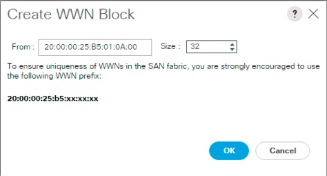
13. Click OK.
14. Click Finish.
15. In the confirmation message, click OK.
16. Right-click WWPN Pools under the root organization.
17. Select Create WWPN Pool to create the WWPN pool.
18. Enter WWPN_Pool_B as the name of the WWPN pool.
19. Optional: Enter a description for the WWPN pool.
20. Select Sequential for Assignment Order.
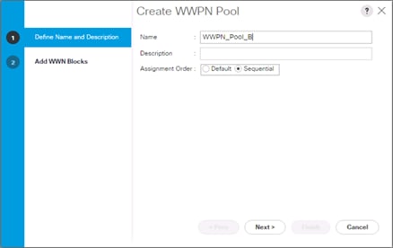
21. Click Next.
22. Click Add.
23. Specify a starting WWPN.
![]() For the FlashStack solution, the recommendation is to place 0B in the next-to-last octet of the starting WWPN to identify all of the WWPNs as fabric A addresses. Merging this with the pattern we used for the WWNN we see a WWPN block starting with 20:00:00:25:B5:01:0B:00.
For the FlashStack solution, the recommendation is to place 0B in the next-to-last octet of the starting WWPN to identify all of the WWPNs as fabric A addresses. Merging this with the pattern we used for the WWNN we see a WWPN block starting with 20:00:00:25:B5:01:0B:00.
24. Specify a size for the WWPN address pool that is sufficient to support the available blade or server resources.

25. Click OK.
26. Click Finish.
27. In the confirmation message, click OK.
Set Packages and Policies
Create Host Firmware Package
Firmware management policies allow the administrator to select the corresponding packages for a given server configuration. These policies often include packages for adapter, BIOS, board controller, FC adapters, host bus adapter (HBA) option ROM, and storage controller properties.
To create a firmware management policy for a given server configuration in the Cisco UCS environment, complete the following steps:
1. In Cisco UCS Manager, click the Servers tab in the navigation pane.
2. Select Policies > root.
3. Expand Host Firmware Packages.
4. Select default.
5. In the Actions pane, select Modify Package Versions.
6. Select the version 3.2(1d)B for the Blade Package, and optionally set version 3.2(1d)C for the Rack Package.
7. Leave Excluded Components with only Local Disk selected.
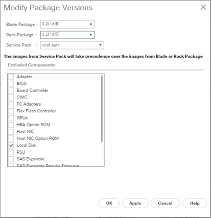
8. Click OK to modify the host firmware package and OK again to acknowledge the changes.
Create Server Pool Qualification Policy (Optional)
To create an optional server pool qualification policy for the Cisco UCS environment, complete the following steps:
![]() This example creates a policy for Cisco UCS B200 M5 servers for a server pool.
This example creates a policy for Cisco UCS B200 M5 servers for a server pool.
1. In Cisco UCS Manager, click the Servers tab in the navigation pane.
2. Select Policies > root.
3. Right-click Server Pool Policy Qualifications.
4. Select Create Server Pool Policy Qualification.
5. Name the policy UCS-B200M5.
6. Select Create Server PID Qualifications.
7. Select UCS-B200-M5 from the PID drop-down.
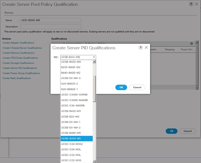
8. Click OK.
9. Optionally select additional qualifications to refine server selection parameters for the server pool.
10. Click OK to create the policy then click OK for the confirmation.
Download Cisco Custom Image for ESXi 6.5 U1
The VMware Cisco Custom Image will need to be downloaded for use during installation by manual access to the UCS KVM vMedia, or through a vMedia Policy covered in the subsection that follows these steps. To download the Cisco Custom Image, complete the following steps:
1. Click the following link: VMware vSphere Hypervisor Cisco Custom Image (ESXi) 6.5 U1.
2. You will need a user id and password on vmware.com to download this software.
3. Download the .iso file.
Create vMedia Policy for VMware ESXi 6.5 U1 Install Boot (optional if manually attaching ISO through KVM)
A separate HTTP web server is required to automate the availability of the ESXi image to each Service Profile on first power on. The creation of this web server is not covered in this document, but can be any existing web server capable of serving files via HTTP that are accessible on the OOB network that the ESXi image can be placed upon.
Place the Cisco Custom Image VMware ESXi 6.5 U1 ISO on the HTTP server and complete the following steps to create a vMedia Policy:
1. In Cisco UCS Manager, select Servers on the left.
2. Select Policies > root.
3. Right-click vMedia Policies.
4. Select Create vMedia Policy.
5. Name the policy ESXi-6.5U1-HTTP.
6. Enter “Mounts ISO for ESXi 6.5 U1” in the Description field.
7. Click Add.
8. Name the mount ESXi-6.5U1-HTTP.
9. Select the CDD Device Type.
10. Select the HTTP Protocol.
11. Enter the IP Address of the web server.
![]() Since DNS server IPs were not entered into the KVM IP earlier, it is necessary to enter the IP of the web server instead of the hostname.
Since DNS server IPs were not entered into the KVM IP earlier, it is necessary to enter the IP of the web server instead of the hostname.
12. Leave “None” selected for Image Name Variable.
13. Enter Vmware-ESXi-6.5.0-5969303-Custom-Cisco-6.5.1.1.iso as the Remote File name.
14. Enter the web server path to the ISO file in the Remote Path field.
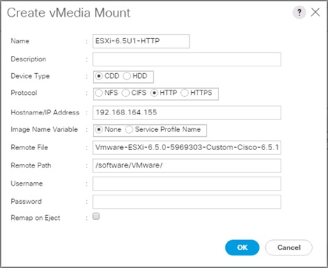
15. Click OK to create the vMedia Mount.
16. Click OK then OK again to complete creating the vMedia Policy.
![]() For any new servers added to the Cisco UCS environment the vMedia service profile template can be used to install the ESXi host. On first boot the host will boot into the ESXi installer. After ESXi is installed, the vMedia will not be referenced as long as the boot disk is accessible.
For any new servers added to the Cisco UCS environment the vMedia service profile template can be used to install the ESXi host. On first boot the host will boot into the ESXi installer. After ESXi is installed, the vMedia will not be referenced as long as the boot disk is accessible.
Create Server BIOS Policy
To create a server BIOS policy for the Cisco UCS environment, complete the following steps:
1. In Cisco UCS Manager, click Servers on the left.
2. Select Policies > root.
3. Right-click BIOS Policies.
4. Select Create BIOS Policy.
5. Enter VM-Host as the BIOS policy name.
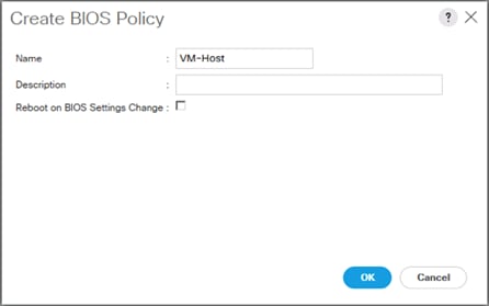
6. Select and right-click the newly created BIOS Policy.
7. Within the Main tab of the Policy:
8. Change CDN Control to enabled.
9. Change the Quiet Boot setting to disabled.
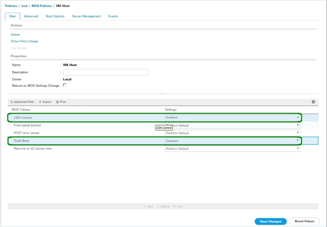
10. Click the Advanced tab, leaving the Processor tab selected within the Advanced tab.
11. Set the following within the Processor tab:
a. DRAM Clock Throttling -> Performance
b. Frequency Floor Override -> Enabled
c. Processor C State -> Disabled
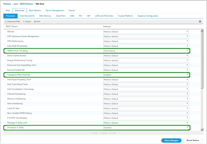
12. Scroll down to the remaining Processor options and select:
a. Processor C1E -> disabled
b. Processor C3 Report -> disabled
c. Processor C7 Report -> disabled
d. Energy Performance -> performance
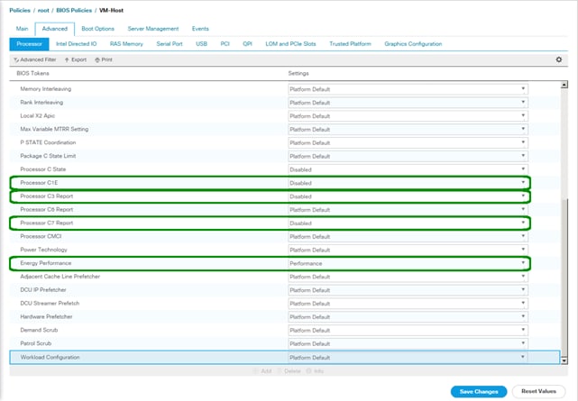
13. Click the RAS Memory tab, and select:
a. LV DDR Mode -> performance-mode
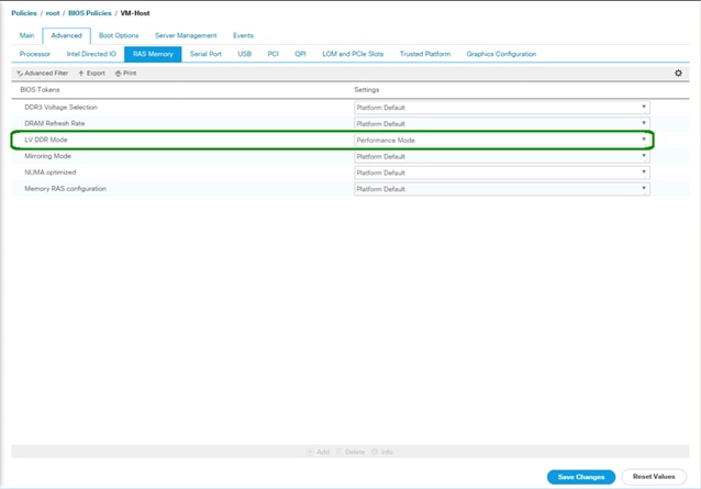
14. Click Save Changes.
15. Click OK.
Update the Default Maintenance Policy
To update the default Maintenance Policy, complete the following steps:
1. In Cisco UCS Manager, click the Servers tab in the navigation pane.
2. Select Policies > root.
3. Select Maintenance Policies > default.
4. Change the Reboot Policy to User Ack.
5. (Optional: Click “On Next Boot” to delegate maintenance windows to server owners).
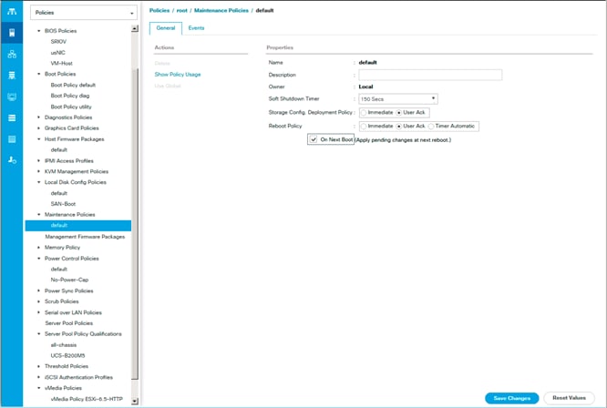
6. Click Save Changes.
7. Click OK to accept the change.
Create Local Disk Configuration Policy (Optional)
A local disk configuration for the Cisco UCS environment is necessary if the servers in the environment do not have a local disk.
![]() This policy should not be used on servers that contain local disks.
This policy should not be used on servers that contain local disks.
To create a local disk configuration policy, complete the following steps:
1. In Cisco UCS Manager, click the Servers tab in the navigation pane.
2. Select Policies > root.
3. Right-click Local Disk Config Policies.
4. Select Create Local Disk Configuration Policy.
5. Enter SAN-Boot as the local disk configuration policy name.
6. Change the mode to No Local Storage.
7. Click OK to create the local disk configuration policy.
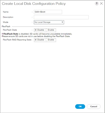
8. Click OK.
Create Power Control Policy
To create a power control policy for the Cisco UCS environment, complete the following steps:
1. In Cisco UCS Manager, click the Servers tab in the navigation pane.
2. Select Policies > root.
3. Right-click Power Control Policies.
4. Select Create Power Control Policy.
5. Enter No-Power-Cap as the power control policy name.
6. Change the power capping setting to No Cap.
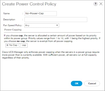
7. Click OK to create the power control policy.
8. Click OK.
Create Network Control Policy for Cisco Discovery Protocol
To create a network control policy that enables Cisco Discovery Protocol (CDP) on virtual network ports, complete the following steps:
1. In Cisco UCS Manager, click the LAN tab in the navigation pane.
2. Select Policies > root.
3. Right-click Network Control Policies.
4. Select Create Network Control Policy.
5. Enter Enable_CDP as the policy name.
6. For CDP, select the Enabled option.
7. Click OK to create the network control policy.
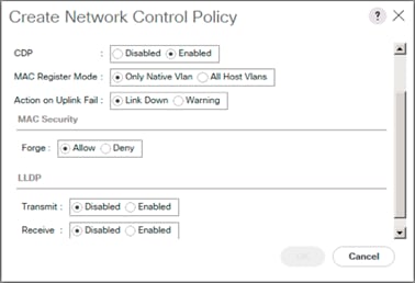
8. Click OK.
Configure UCS LAN Connectivity
Create Uplink Port Channels
To configure the necessary port channels out of the Cisco UCS environment, complete the following steps:
1. In Cisco UCS Manager, click the LAN tab in the navigation pane.
![]() In this procedure, two port channels are created: one from fabric A to both Cisco Nexus switches and one from fabric B to both Cisco Nexus switches.
In this procedure, two port channels are created: one from fabric A to both Cisco Nexus switches and one from fabric B to both Cisco Nexus switches.
2. Under LAN > LAN Cloud, expand the Fabric A tree.
3. Right-click Port Channels.
4. Select Create Port Channel.
5. Enter a unique ID for the port channel, (151 in our example to correspond with the upstream Nexus port channel).
6. With 151 selected, enter vPC-151-Nexus as the name of the port channel.
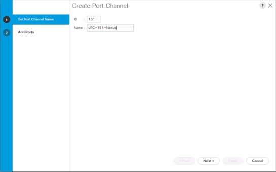
7. Click Next.
8. Select the following ports to be added to the port channel:
- Slot ID 1 and port 39
- Slot ID 1 and port 40

9. Click >> to add the ports to the port channel.
10. Click Finish to create the port channel.
11. Click OK.
12. In the navigation pane, under LAN > LAN Cloud, expand the fabric B tree.
13. Right-click Port Channels.
14. Select Create Port Channel.
15. Enter a unique ID for the port channel, (152 in our example to correspond with the upstream Nexus port channel).
16. With 152 selected, enter vPC-152-Nexus as the name of the port channel.
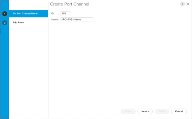
17. Click Next.
18. Select the following ports to be added to the port channel:
- Slot ID 1 and port 39
- Slot ID 1 and port 40
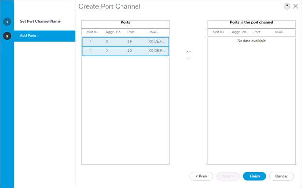
19. Click >> to add the ports to the port channel.
20. Click Finish to create the port channel.
21. Click OK.
Create VLANs
To configure the necessary virtual local area networks (VLANs) for the Cisco UCS environment, complete the following steps:
1. In Cisco UCS Manager, click the LAN tab in the navigation pane.
![]() In this procedure, six unique VLANs are created. See Table 2 for a list of VLANs to be created.
In this procedure, six unique VLANs are created. See Table 2 for a list of VLANs to be created.
2. Select LAN > LAN Cloud.
3. Right-click VLANs.
4. Select Create VLANs.
5. Enter Native-VLAN as the name of the VLAN to be used as the native VLAN.
6. Keep the Common/Global option selected for the scope of the VLAN.
7. Enter the native VLAN ID.
8. Keep the Sharing Type as None.
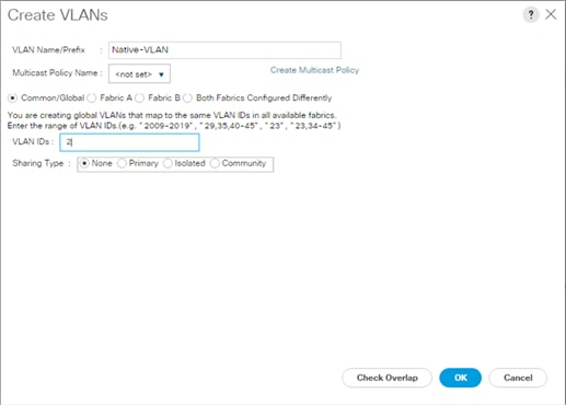
9. Click OK and then click OK again.
10. Expand the list of VLANs in the navigation pane, right-click the newly created Native-VLAN and select Set as Native VLAN.
11. Click Yes and then click OK.
12. Right-click VLANs.
13. Select Create VLANs
14. Enter IB-Mgmt as the name of the VLAN to be used for management traffic.
15. Keep the Common/Global option selected for the scope of the VLAN.
16. Enter the In-Band management VLAN ID.
17. Keep the Sharing Type as None.
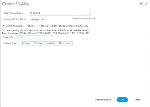
18. Click OK and then click OK again.
19. Right-click VLANs.
20. Select Create VLANs.
21. Enter vMotion as the name of the VLAN to be used for vMotion.
22. Keep the Common/Global option selected for the scope of the VLAN.
23. Enter the vMotion VLAN ID.
24. Keep the Sharing Type as None.

25. Click OK and then click OK again.
26. Right-click VLANs.
27. Select Create VLANs.
28. Enter VM-App- as the prefix of the VLANs to be used for VM Traffic.
29. Keep the Common/Global option selected for the scope of the VLAN.
30. Enter the VM-Traffic VLAN ID range.
31. Keep the Sharing Type as None.
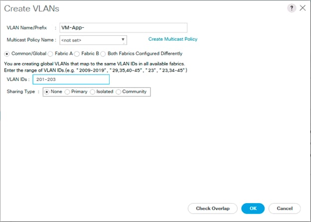
32. Click OK and then click OK again.
33. Repeat as needed for any additional VLANs created on the upstream Nexus switches.
Create vNIC Templates
To create the multiple virtual network interface card (vNIC) templates for the Cisco UCS environment, complete the following steps:
Create Management vNICs
For the vNIC_Mgmt_A Template, complete the following steps:
1. In Cisco UCS Manager, click the LAN tab in the navigation pane.
2. Select Policies > root.
3. Right-click vNIC Templates.
4. Select Create vNIC Template.
5. Enter vNIC_Mgmt_A as the vNIC template name.
6. Keep Fabric A selected.
7. Optional: select the Enable Failover checkbox.
![]() Selecting Failover can improve link failover time by handling it at the hardware level and can guard against any potential for NIC failure not being detected by the virtual switch.
Selecting Failover can improve link failover time by handling it at the hardware level and can guard against any potential for NIC failure not being detected by the virtual switch.
8. Select Primary Template for the Redundancy Type.
9. Leave Peer Redundancy Template as <not set>
![]() Redundancy Type and specification of Redundancy Template are configuration options to later allow changes to the Primary Template to automatically adjust onto the Secondary Template.
Redundancy Type and specification of Redundancy Template are configuration options to later allow changes to the Primary Template to automatically adjust onto the Secondary Template.
10. Under Target, make sure that the VM checkbox is not selected.
11. Select Updating Template as the Template Type.
12. Under VLANs, select the checkboxes for IB-Mgmt and Native-VLAN VLANs.
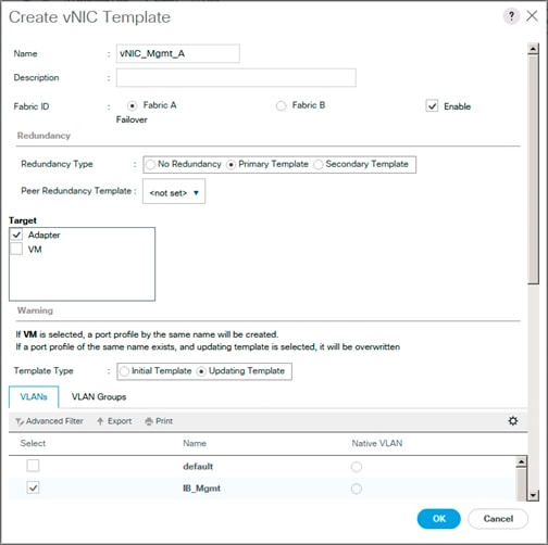
13. Set Native-VLAN as the native VLAN.
14. Leave vNIC Name selected for the CDN Source.
15. Leave 1500 for the MTU.
16. In the MAC Pool list, select MAC_Pool_A.
17. In the Network Control Policy list, select Enable_CDP.
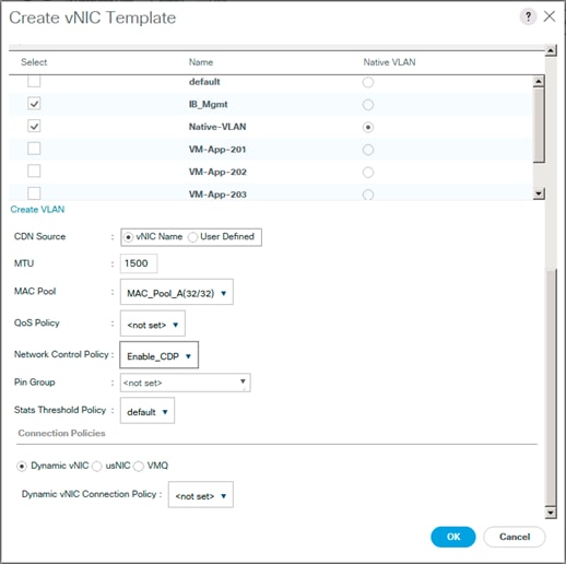
18. Click OK to create the vNIC template.
19. Click OK.
For the vNIC_Mgmt_B Template, complete the following steps:
1. In the navigation pane, select the LAN tab.
2. Select Policies > root.
3. Right-click vNIC Templates.
4. Select Create vNIC Template
5. Enter vNIC_Mgmt_B as the vNIC template name.
6. Select Fabric B.
7. Select Secondary Template for Redundancy Type.
8. For the Peer Redundancy Template drop-down, select vNIC_Mgmt_A.
![]() With Peer Redundancy Template selected, Failover specification, Template Type, VLANs, CDN Source, MTU, and Network Control Policy are all pulled from the Primary Template.
With Peer Redundancy Template selected, Failover specification, Template Type, VLANs, CDN Source, MTU, and Network Control Policy are all pulled from the Primary Template.
9. Under Target, make sure the VM checkbox is not selected.
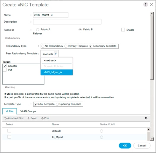
10. In the MAC Pool list, select MAC_Pool_B.

11. Click OK to create the vNIC template.
12. Click OK.
Create vMotion vNICs
For the vNIC_vMotion_A Template, complete the following steps:
1. In Cisco UCS Manager, click the LAN tab in the navigation pane.
2. Select Policies > root.
3. Right-click vNIC Templates.
4. Select Create vNIC Template.
5. Enter vNIC_vMotion_A as the vNIC template name.
6. Keep Fabric A selected.
7. Optional: select the Enable Failover checkbox.
8. Select Primary Template for the Redundancy Type.
9. Leave Peer Redundancy Template as <not set>
10. Under Target, make sure that the VM checkbox is not selected.
11. Select Updating Template as the Template Type.
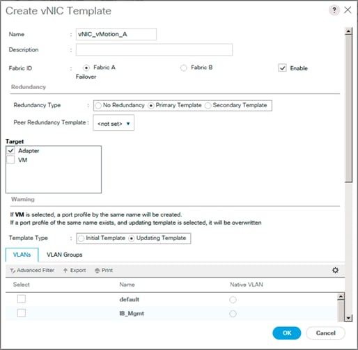
12. Under VLANs, select the checkboxes vMotion as the only VLAN.
13. Set vMotion as the native VLAN.
14. For MTU, enter 9000.
15. In the MAC Pool list, select MAC_Pool_A.
16. In the Network Control Policy list, select Enable_CDP.
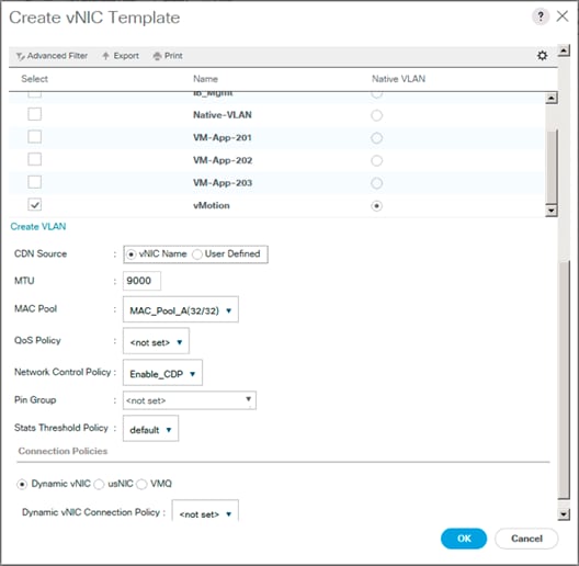
17. Click OK to create the vNIC template.
18. Click OK.
For the vNIC_vMotion_B Template, complete the following steps:
1. In the navigation pane, select the LAN tab.
2. Select Policies > root.
3. Right-click vNIC Templates.
4. Select Create vNIC Template
5. Enter vNIC_vMotion_B as the vNIC template name.
6. Select Fabric B.
7. Select Secondary Template for Redundancy Type.
8. For the Peer Redundancy Template drop-down, select vNIC_vMotion_A.
![]() With Peer Redundancy Template selected, MAC Pool will be the main configuration option left for this vNIC template.
With Peer Redundancy Template selected, MAC Pool will be the main configuration option left for this vNIC template.
9. Under Target, make sure the VM checkbox is not selected.
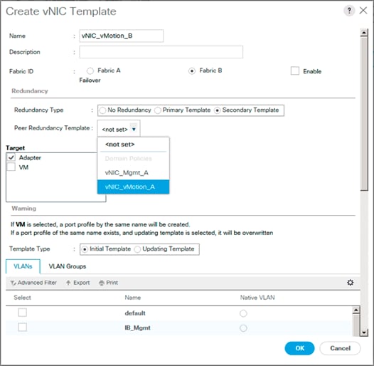
10. In the MAC Pool list, select MAC_Pool_B.
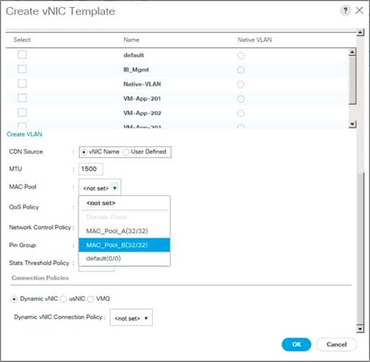
11. Click OK to create the vNIC template.
12. Click OK.
Create Application vNICs
For the vNIC_App_A Template, complete the following steps:
1. In Cisco UCS Manager, click the LAN tab in the navigation pane.
2. Select Policies > root.
3. Right-click vNIC Templates.
4. Select Create vNIC Template.
5. Enter vNIC_App_A as the vNIC template name.
6. Keep Fabric A selected.
7. Optional: select the Enable Failover checkbox.
8. Select Primary Template for the Redundancy Type.
9. Leave Peer Redundancy Template as <not set>
10. Under Target, make sure that the VM checkbox is not selected.
11. Select Updating Template as the Template Type.
12. Set default as the native VLAN.
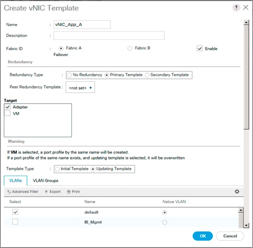
13. Under VLANs, select the checkboxes for any application or production VLANs that should be delivered to the ESXi hosts.
14. For MTU, enter 9000.
15. In the MAC Pool list, select MAC_Pool_A.
16. In the Network Control Policy list, select Enable_CDP.
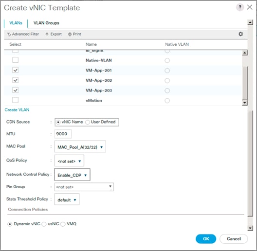
17. Click OK to create the vNIC template.
18. Click OK.
For the vNIC_App_B Template, complete the following steps:
1. In the navigation pane, select the LAN tab.
2. Select Policies > root.
3. Right-click vNIC Templates.
4. Select Create vNIC Template
5. Enter vNIC_App_B as the vNIC template name.
6. Select Fabric B.
7. Select Secondary Template for Redundancy Type.
8. For the Peer Redundancy Template drop-down, select vNIC_App_A.
![]() With Peer Redundancy Template selected, MAC Pool will be the main configuration option left for this vNIC template.
With Peer Redundancy Template selected, MAC Pool will be the main configuration option left for this vNIC template.
9. Under Target, make sure the VM checkbox is not selected.
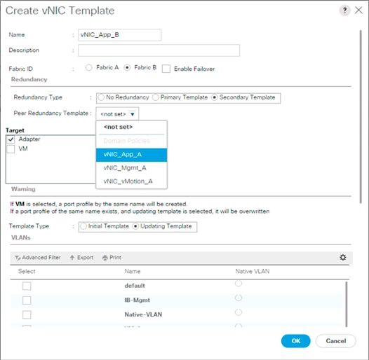
10. In the MAC Pool list, select MAC_Pool_B.

11. Click OK to create the vNIC template.
12. Click OK.
Set Jumbo Frames in Cisco UCS Fabric
To configure jumbo frames and enable quality of service in the Cisco UCS fabric, complete the following steps:
1. In Cisco UCS Manager, click the LAN tab in the navigation pane.
2. Select LAN > LAN Cloud > QoS System Class.
3. In the right pane, click the General tab.
4. On the Best Effort row, enter 9216 in the box under the MTU column.
5. Click Save Changes in the bottom of the window.
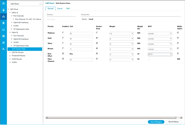
6. Click OK
Create LAN Connectivity Policy
To configure the necessary Fibre Channel Infrastructure LAN Connectivity Policy, complete the following steps:
1. In Cisco UCS Manager, click the LAN tab in the navigation pane.
2. Select LAN > Policies > root.
3. Right-click LAN Connectivity Policies.
4. Select Create LAN Connectivity Policy.
5. Enter FC-LAN-Policy as the name of the policy.
6. Click the upper Add button to add a vNIC.
7. In the Create vNIC dialog box, enter 00-Mgmt-A as the name of the vNIC.
![]() The numeric prefix of “00-“ and subsequent increments on the later vNICs are used in the vNIC naming to force the device ordering through Consistent Device Naming (CDN). Without this, some operating systems might not respect the device ordering that is set within Cisco UCS.
The numeric prefix of “00-“ and subsequent increments on the later vNICs are used in the vNIC naming to force the device ordering through Consistent Device Naming (CDN). Without this, some operating systems might not respect the device ordering that is set within Cisco UCS.
8. Select the Use vNIC Template checkbox.
9. In the vNIC Template list, select vNIC_Mgmt_A.
10. In the Adapter Policy list, select VMWare.
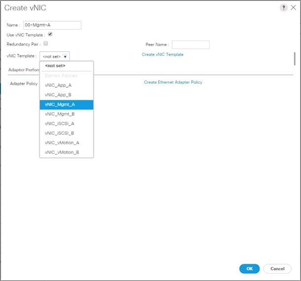
11. Click OK to add this vNIC to the policy.
12. Click the upper Add button to add another vNIC to the policy.
13. In the Create vNIC box, enter 01-Mgmt-B as the name of the vNIC.
14. Select the Use vNIC Template checkbox.
15. In the vNIC Template list, select vNIC_Mgmt_B.
16. In the Adapter Policy list, select VMWare.
17. Click OK to add the vNIC to the policy.
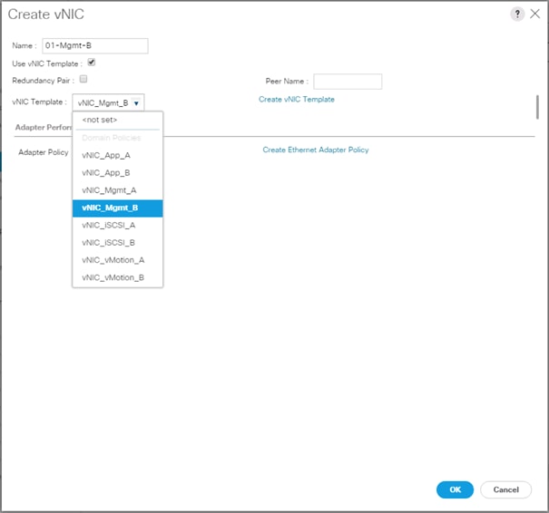
18. Click the upper Add button to add a vNIC.
19. In the Create vNIC dialog box, enter 02-vMotion-A as the name of the vNIC.
20. Select the Use vNIC Template checkbox.
21. In the vNIC Template list, select vNIC_vMotion_A.
22. In the Adapter Policy list, select VMWare.
23. Click OK to add this vNIC to the policy.
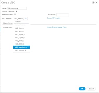
24. Click the upper Add button to add a vNIC to the policy.
25. In the Create vNIC dialog box, enter 03-vMotion-B as the name of the vNIC.
26. Select the Use vNIC Template checkbox.
27. In the vNIC Template list, select vNIC_vMotion_B.
28. In the Adapter Policy list, select VMWare.
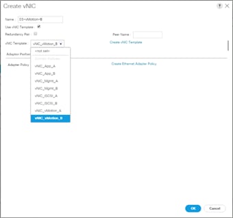
29. Click OK to add this vNIC to the policy.
30. Click the upper Add button to add a vNIC.
31. In the Create vNIC dialog box, enter 04-App-A as the name of the vNIC.
32. Select the Use vNIC Template checkbox.
33. In the vNIC Template list, select vNIC_App_A.
34. In the Adapter Policy list, select VMWare.
35. Click OK to add this vNIC to the policy.
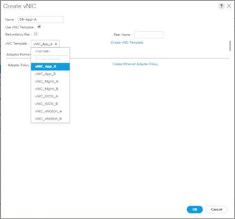
36. Click the upper Add button to add a vNIC to the policy.
37. In the Create vNIC dialog box, enter 05-App-B as the name of the vNIC.
38. Select the Use vNIC Template checkbox.
39. In the vNIC Template list, select vNIC_App_B.
40. In the Adapter Policy list, select VMWare.
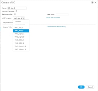
41. Click OK to add this vNIC to the policy.
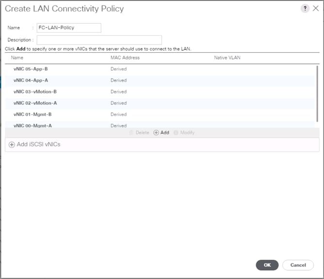
42. Click OK to create the LAN Connectivity Policy.
43. Click OK.
Configure FC SAN Connectivity
These Fibre Channel configuration steps will enable the FlashStack for provisioning of volumes to be used as datastores by the FlashStack vSphere hosts, and the creation of UCS Service Profiles that will be configured to boot from Fibre Channel LUNs.
Configure Unified Ports
The Cisco UCS 6332-16UP Fabric Interconnects will have a slider mechanism within the Cisco UCS Manager GUI interface that will control the first 16 ports starting from the first port, and configured in increments of the first 6, 12, or all 16 of the unified ports.
To enable the fibre channel ports, complete the following steps:
1. In Cisco UCS Manager, click the Equipment tab in the navigation pane.
2. Select Equipment > Fabric Interconnects > Fabric Interconnect A (primary)
3. Select Configure Unified Ports.
4. Click Yes on the pop-up window warning that changes to the fixed module will require a reboot of the fabric interconnect and changes to the expansion module will require a reboot of that module.
5. Within the Configured Fixed Ports pop-up window move the gray slider bar from the left to the right to select either 6, 12, or 16 ports to be set as FC Uplinks.
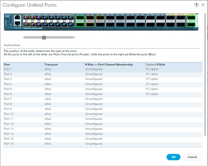
6. Click OK to continue
7. Select Equipment > Fabric Interconnects > Fabric Interconnect B (primary)
8. Select Configure Unified Ports.
9. Click Yes on the pop-up window warning that changes to the fixed module will require a reboot of the fabric interconnect and changes to the expansion module will require a reboot of that module.
10. Within the Configured Fixed Ports pop-up window move the gray slider bar from the left to the right to select either 6, 12, or 16 ports to be set as FC Uplinks.
11. Click OK to continue
![]() The Fabric Interconnects will reboot, reconnect to UCS Manager after they are back up.
The Fabric Interconnects will reboot, reconnect to UCS Manager after they are back up.
Create VSANs
To configure the necessary virtual storage area networks (VSANs) for the Cisco UCS environment, complete the following steps:
1. In Cisco UCS Manager, click the SAN tab in the navigation pane.
![]() In this procedure, two VSANs are created.
In this procedure, two VSANs are created.
2. Select SAN > SAN Cloud.
3. Right-click VSANs.
4. Select Create VSAN.
5. Enter VSAN_A as the name of the VSAN to be used for Fabric A
6. Leave Disabled selected for FC Zoning.
7. Select Fabric A.
8. Enter a unique VSAN ID and a corresponding FCoE VLAN ID. It is recommended use the same ID for both parameters and to use something other than 1.
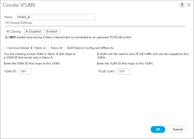
9. Click OK and then click OK again.
10. Under SAN Cloud, right-click VSANs.
11. Select Create VSAN.
12. Enter VSAN_B as the name of the VSAN to be used for Fabric B.
13. Leave Disabled selected for FC Zoning.
14. Select Fabric B.
15. Enter a unique VSAN ID and a corresponding FCoE VLAN ID. It is recommended use the same ID for both parameters and to use something other than 1.

16. Click OK and then click OK again.
Create FC Port Channels
To configure the necessary port channels for the Cisco UCS environment, complete the following steps:
Fabric-A
1. In the navigation pane under SAN > SAN Cloud expand the Fabric A tree.
2. Right-click FC Port Channels.
3. Select Create Port Channel.
4. Enter 1 for the ID and Po1 for the Port Channel name.
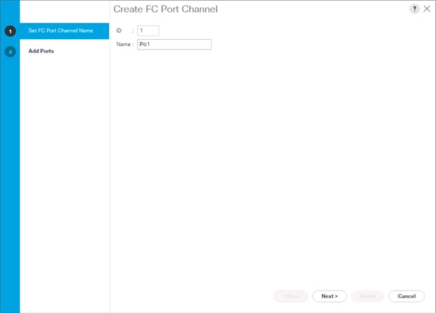
5. Click Next then choose appropriate ports and click >> to add the ports to the port channel.
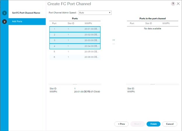
6. Click Finish.
7. Click OK.
8. Select the newly created Port-Channel.
9. Under the VSAN drop-down for Port-Channel 1, select VSAN_A 101.
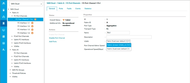
10. Click Save Changes and then click OK.
Fabric-B
1. In the navigation pane, under SAN > SAN Cloud, expand the Fabric B tree.
2. Right-click FC Port Channels.
3. Select Create Port Channel.
4. Enter 2 for the ID and Po2 for the Port Channel name.
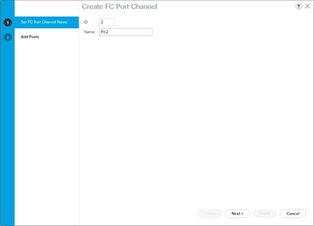
5. Click Next then choose appropriate the ports and click >> to add the ports to the port channel.
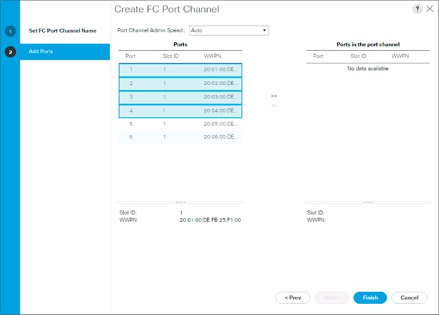
6. Click Finish.
7. Click OK.
8. Select the newly created Port-Channel
9. Under the VSAN drop-down for Port-Channel 2, select VSAN_B 102.
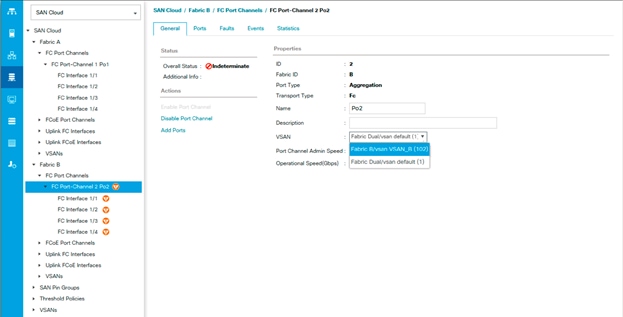
10. Click Save Changes and then click OK.
Create vHBA Templates
To create the necessary virtual host bus adapter (vHBA) templates for the Cisco UCS environment, complete the following steps:
1. In Cisco UCS Manager, click the SAN tab in the navigation pane.
2. Select Policies > root.
3. Right-click vHBA Templates.
4. Select Create vHBA Template.
5. Enter vHBA_Template_A as the vHBA template name.
6. Keep Fabric A selected.
7. Leave Redundancy Type as No Redundancy.
8. Select VSAN_A.
9. Leave Initial Template as the Template Type.
10. Select WWPN_Pool_A as the WWPN Pool.
11. Click OK to create the vHBA template.
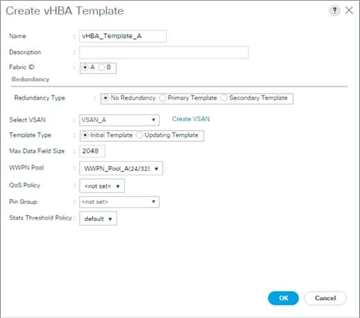
12. Click OK.
13. Right-click vHBA Templates.
14. Select Create vHBA Template.
15. Enter vHBA_Template_B as the vHBA template name.
16. Select Fabric B as the Fabric ID.
17. Select VSAN_B.
18. Leave Redundancy Type as No Redundancy.
19. Leave Initial Template as the Template Type.
20. Select WWPN_Pool_B as the WWPN Pool.
21. Click OK to create the vHBA template.

22. Click OK.
Create SAN Connectivity Policy
To configure the necessary Infrastructure SAN Connectivity Policy, complete the following steps:
1. In Cisco UCS Manager, click the SAN tab in the navigation pane.
2. Select SAN > Policies > root.
3. Right-click SAN Connectivity Policies.
4. Select Create SAN Connectivity Policy.
5. Enter Infra-SAN-Policy as the name of the policy.
6. Select the previously created WWNN_Pool for the WWNN Assignment.
7. Click the Add button at the bottom to add a vHBA.
8. In the Create vHBA dialog box, enter Fabric-A as the name of the vHBA.
9. Select the Use vHBA Template checkbox.
10. Leave Redundancy Pair unselected.
11. In the vHBA Template list, select vHBA_Template_A.
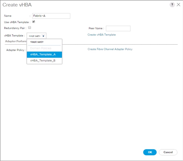
12. In the Adapter Policy list, select VMWare.
13. Click OK.
14. Click the Add button at the bottom to add a second vHBA.
15. In the Create vHBA dialog box, enter Fabric-B as the name of the vHBA.
16. Select the Use vHBA Template checkbox.
17. Leave Redundancy Pair unselected.
18. In the vHBA Template list, select vHBA_Template_B.
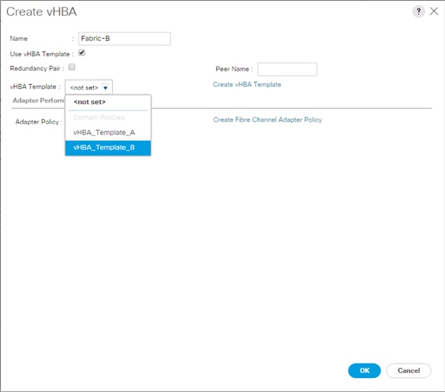
19. In the Adapter Policy list, select VMWare.
20. Click OK.
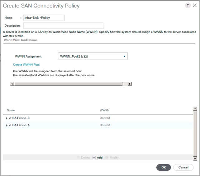
21. Click OK to create the SAN Connectivity Policy.
22. Click OK to confirm creation.
Create Boot Policy
This procedure will define the Primary and Secondary Boot Targets for each Fabric side (A/B). These will be the WWNs that need to be collected from the first adapter of each controller on the Pure Storage FlashArray that are visible from the System Health tab under the System section of the FlashArray Web GUI.
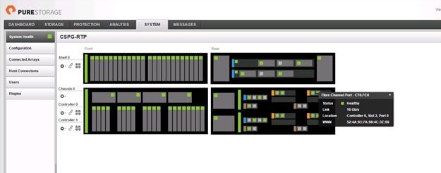
As an alternative to the GUI, connect to the FlashArray//X via ssh using the pureuser account and find the WWNs using the pureport list command:
pureuser@cspg-rtp-2> pureport list
Name WWN Portal IQN Failover
CT0.ETH8 - 10.164.101.41:3260 iqn.2010-06.com.purestorage:flasharray.491a50eccb3c035 -
CT0.ETH9 - 10.164.102.41:3260 iqn.2010-06.com.purestorage:flasharray.491a50eccb3c035 -
CT0.FC0 52:4A:93:76:87:FF:47:00 - - -
CT0.FC1 52:4A:93:76:87:FF:47:01 - - -
CT0.FC2 52:4A:93:76:87:FF:47:02 - - -
CT0.FC3 52:4A:93:76:87:FF:47:03 - - -
CT0.FC6 52:4A:93:76:87:FF:47:06 - - -
CT0.FC7 52:4A:93:76:87:FF:47:07 - - -
CT1.ETH8 - 10.164.101.42:3260 iqn.2010-06.com.purestorage:flasharray.491a50eccb3c035 -
CT1.ETH9 - 10.164.102.42:3260 iqn.2010-06.com.purestorage:flasharray.491a50eccb3c035 -
CT1.FC0 52:4A:93:76:87:FF:47:10 - - -
CT1.FC1 52:4A:93:76:87:FF:47:11 - - -
CT1.FC2 52:4A:93:76:87:FF:47:12 - - -
CT1.FC3 52:4A:93:76:87:FF:47:13 - - -
CT1.FC6 52:4A:93:76:87:FF:47:16 - - -
CT1.FC7 52:4A:93:76:87:FF:47:17 - -
Find the FC0 adapters for each controller from within the System view and record the values to be used for Primary and Secondary Targets. In the example lab environment, these appear as the first ports on the right side of each controller shown.
Table 14 Fabric A Boot Targets for the FlashArray//X
|
| Port Name | Target Role | WWN/WWPN Example Environment | WWN/WWPN Customer Environment |
| FlashArray//X Controller 0 | CT0.FC0 | Primary | 52:4A:93:76:87:FF:47:00 |
|
| FlashArray//X Controller 1 | CT1.FC0 | Secondary | 52:4A:93:76:87:FF:47:10 |
|
Within the same System view, find the FC1 adapters for each controller and record the values to be used for Primary and Secondary Targets. In the example lab environment, these appear as the second ports on the right side of each controller shown.
Table 15 Fabric B Boot Targets for the FlashArray//X
|
| Port Name | Target Role | WWN/WWPN Example Environment | WWN/WWPN Customer Environment |
| FlashArray//X Controller 0 | CT0.FC1 | Primary | 52:4A:93:76:87:FF:47:01 |
|
| FlashArray//X Controller 1 | CT1.FC1 | Secondary | 52:4A:93:76:87:FF:47:11 |
|
To create boot policies for the Cisco UCS environment, complete the following steps:
1. In Cisco UCS Manager, click the Servers tab in the navigation pane.
2. Select Policies > root.
3. Right-click Boot Policies.
4. Select Create Boot Policy.
5. Enter Boot-FC-X-A as the name of the boot policy.
6. Optional: Enter a description for the boot policy.
![]() Do not select the Reboot on Boot Order Change checkbox.
Do not select the Reboot on Boot Order Change checkbox.
7. Expand the Local Devices drop-down menu and select Add Remote CD/DVD.
8. Expand the vHBAs drop-down menu and select Add SAN Boot.
9. In the Add SAN Boot dialog box, enter Fabric-A in the vHBA field.
10. Confirm that Primary is selected for the Type option.
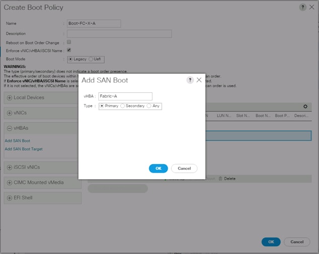
11. Click OK to add the SAN boot initiator.
12. From the vHBA drop-down menu, select Add SAN Boot Target.
13. Enter 1 as the value for Boot Target LUN.
14. Enter the WWPN for CT0.FC0 recorded in Table 14
15. Select Primary for the SAN boot target type.
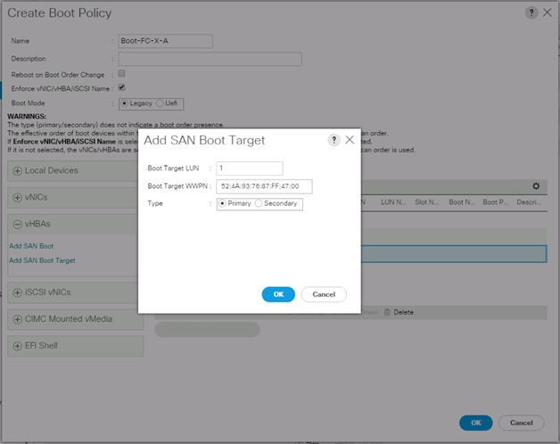
16. Click OK to add the SAN boot target.
17. From the vHBA drop-down menu, select Add SAN Boot Target.
18. Enter 1 as the value for Boot Target LUN.
19. Enter the WWPN for CT1.FC0 recorded in Table 14.
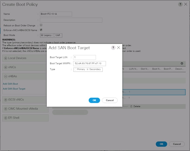
20. Click OK to add the SAN boot target.
21. From the vHBA drop-down menu, select Add SAN Boot.
22. In the Add SAN Boot dialog box, enter Fabric-B in the vHBA box.
![]() The SAN boot type should automatically be set to Secondary, and the Type option should be unavailable.
The SAN boot type should automatically be set to Secondary, and the Type option should be unavailable.
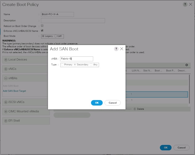
23. Click OK to add the SAN boot initiator.
24. From the vHBA drop-down menu, select Add SAN Boot Target.
25. Enter 1 as the value for Boot Target LUN.
26. Enter the WWPN for CT0.FC1 recorded in Table 14.
27. Select Primary for the SAN boot target type.
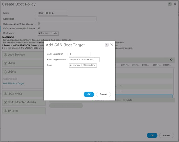
28. Click OK to add the SAN boot target.
29. From the vHBA drop-down menu, select Add SAN Boot Target.
30. Enter 1 as the value for Boot Target LUN.
31. Enter the WWPN for CT1.FC1 recorded in Table 15.
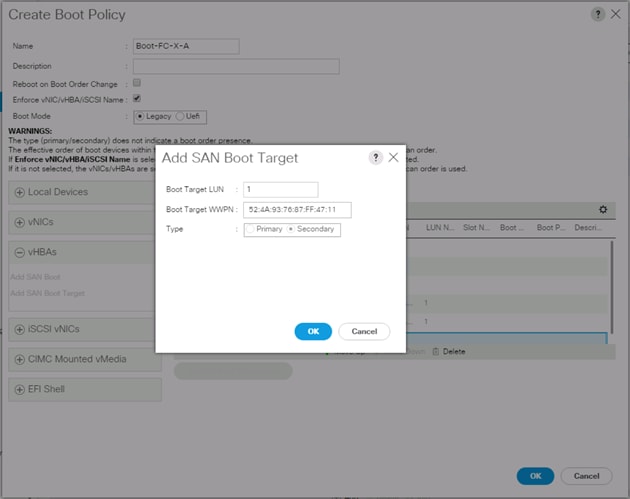
32. Click OK to add the SAN boot target.
33. Expand CIMC Mounted Media and select Add CIMC Mounted CD/DVD.
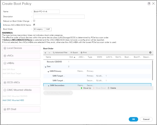
34. Click OK, then click OK again to create the boot policy.
Create Service Profile Template
In this procedure, one service profile template for Infrastructure ESXi hosts is created for fabric A boot.
To create the service profile template, complete the following steps:
1. In Cisco UCS Manager, click the Servers tab in the navigation pane.
2. Select Service Profile Templates > root.
3. Right-click root.
4. Select Create Service Profile Template to open the Create Service Profile Template wizard.
5. Enter VM-Host-FC-A as the name of the service profile template. This service profile template is configured to boot from FlashArray//X controller 1 on fabric A.
6. Select the “Updating Template” option.
7. Under UUID, select UUID_Pool as the UUID pool.
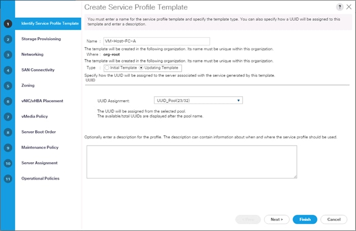
8. Click Next.
Configure Storage Provisioning
1. If you have servers with no physical disks, click the Local Disk Configuration Policy tab and select the SAN-Boot Local Storage Policy. Otherwise, select the default Local Storage Policy.
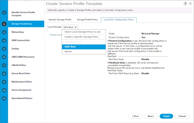
2. Click Next.
Configure Networking Options
To configure the network options, complete the following steps:
1. Keep the default setting for Dynamic vNIC Connection Policy.
2. Select the “Use Connectivity Policy” option to configure the LAN connectivity.
3. Select FC-LAN-Policy from the LAN Connectivity Policy drop-down.
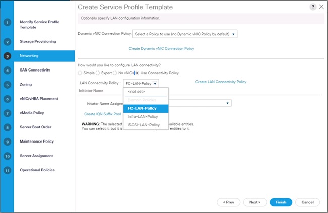
4. Click Next.
Configure Storage Options
1. Select the Use Connectivity Policy option for the “How would you like to configure SAN connectivity?” field.
2. Pick the Infra-SAN-Policy option from the SAN Connectivity Policy drop-down.
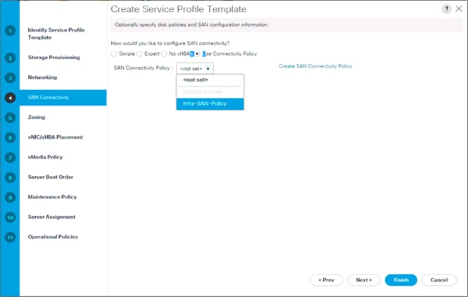
3. Click Next.
Configure Zoning Options
1. Leave Zoning configuration unspecified, and click Next.
Configure vNIC/HBA Placement
1. In the “Select Placement” list, leave the placement policy as “Let System Perform Placement”.
2. Click Next.
Configure vMedia Policy
1. Do not select a vMedia Policy.
2. Click Next.
Configure Server Boot Order
1. Select Boot-FC-X-A for Boot Policy.
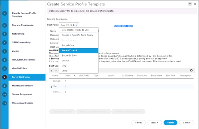
2. Click Next to continue to the next section.
Configure Maintenance Policy
1. Change the Maintenance Policy to default.
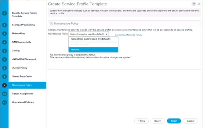
2. Click Next.
Configure Server Assignment
To configure server assignment, complete the following steps:
1. In the Pool Assignment list, select Infra_Pool.
2. Optional: Select a Server Pool Qualification policy.
3. Select Down as the power state to be applied when the profile is associated with the server.
4. Optional: Select “UCS-B200M5” for the Server Pool Qualification.
![]() Firmware Management at the bottom of the page can be left alone as it will use default from the Host Firmware list.
Firmware Management at the bottom of the page can be left alone as it will use default from the Host Firmware list.
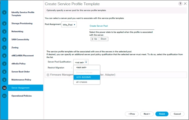
5. Click Next.
Configure Operational Policies
To configure the operational policies, complete the following steps:
1. In the BIOS Policy list, select VM-Host.
2. Expand Power Control Policy Configuration and select No-Power-Cap in the Power Control Policy list.
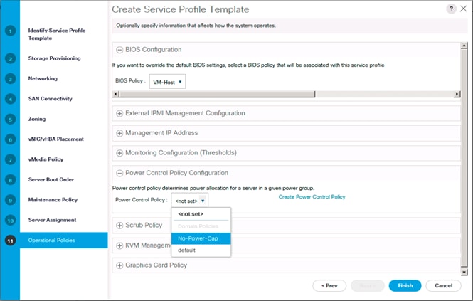
3. Click Finish to create the service profile template.
4. Click OK in the confirmation message.
Create vMedia Service Profile Template
If the optional ESXi 6.5 U1 vMedia Policy is being used, a clone of the created service profile template will be made to reference this vMedia Policy. The clone of the service profile template will have the vMedia Policy configured for it, and service profiles created from it, will be unbound and re-associated to the original service profile template after ESXi installation. To create a clone of the VM-Host-FC-A service profile template, and associate the vMedia Policy to it, complete the following steps:
1. Connect to UCS Manager, click Servers on the left.
2. Select Service Profile Templates > root > Service Template VM-Host-FC-A.
3. Right-click Service Template VM-Host-FC-A and select Create a Clone.
4. Name the clone VM-Host-FC-A-vM and click OK.
5. Select Service Template VM-Host-FC-A-vM.
6. In the right pane, select the vMedia Policy tab.
7. Under Actions, select Modify vMedia Policy.
8. Using the drop-down, select the ESXi-6.5U1-HTTP vMedia Policy.
9. Click OK then OK again to complete modifying the Service Profile Template.
Create Service Profiles
To create service profiles from the service profile template, complete the following steps:
1. Connect to the UCS 6332-16UP Fabric Interconnect UCS Manager, click the Servers tab in the navigation pane.
2. Select Service Profile Templates > root > Service Template VM-Host-FC-A-vM.
3. Right-click VM-Host-FC-A-vM and select Create Service Profiles from Template.
4. Enter VM-Host-FC-0 as the service profile prefix.
5. Leave 1 as “Name Suffix Starting Number.”
6. Leave 2 as the “Number of Instances.”
7. Click OK to create the service profiles.
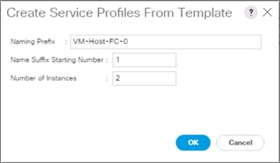
8. Click OK in the confirmation message to provision two FlashStack Service Profiles.
![]() When VMware ESXi 6.5 U1 has been installed on the hosts, the host Service Profiles can be unbound from the VM-Host-FC-A-vM and rebound to the VM-Host-FC-A Service Profile Template to remove the vMedia mapping from the host, to prevent issues at boot time if the HTTP source for the ESXi ISO is somehow not available.
When VMware ESXi 6.5 U1 has been installed on the hosts, the host Service Profiles can be unbound from the VM-Host-FC-A-vM and rebound to the VM-Host-FC-A Service Profile Template to remove the vMedia mapping from the host, to prevent issues at boot time if the HTTP source for the ESXi ISO is somehow not available.
This section continues the configuration of the Cisco MDS 9148S Multilayer Fabric Switches now that resources are attached, to provide zoning for supported devices.
Figure 6 MDS Fabric Zoning Workflow
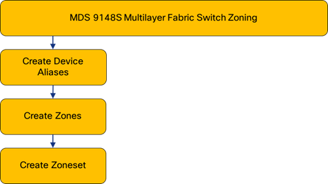
Create Device Aliases for the Connected FlashArray Ports
Gather the WWPN of the FlashArray adapters using the show flogi database command on each switch and create a spreadsheet to reference when creating device aliases on each MDS. For MDS 9148S A this will be:
mds-9148s-a# sh flogi database
--------------------------------------------------------------------------------
INTERFACE VSAN FCID PORT NAME NODE NAME
--------------------------------------------------------------------------------
fc1/1 1 0x5d0000 52:4a:93:76:87:ff:47:00 52:4a:93:76:87:ff:47:00
fc1/2 1 0x5d0100 52:4a:93:76:87:ff:47:02 52:4a:93:76:87:ff:47:02
fc1/3 1 0x5d0200 52:4a:93:76:87:ff:47:10 52:4a:93:76:87:ff:47:10
fc1/4 1 0x5d0300 52:4a:93:76:87:ff:47:12 52:4a:93:76:87:ff:47:12
port-channel1 101 0xe00400 24:01:00:de:fb:07:c9:80 20:65:00:de:fb:07:c9:81
Match these values to their sources previously collected in Table 14 and Table 15 from the Pure Storage Portal System Health view:
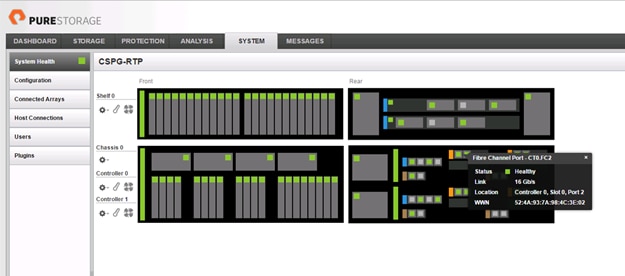
or the pure Purity command line output gained from an ssh connection to the FlashArray using the pureuser account:
pureuser@cspg-rtp-2> pureport list
Name WWN Portal IQN Failover
CT0.ETH8 - 10.164.101.41:3260 iqn.2010-06.com.purestorage:flasharray.491a50eccb3c035 -
CT0.ETH9 - 10.164.102.41:3260 iqn.2010-06.com.purestorage:flasharray.491a50eccb3c035 -
CT0.FC0 52:4A:93:76:87:FF:47:00 - - -
CT0.FC1 52:4A:93:76:87:FF:47:01 - - -
CT0.FC2 52:4A:93:76:87:FF:47:02 - - -
CT0.FC3 52:4A:93:76:87:FF:47:03 - - -
CT0.FC6 52:4A:93:76:87:FF:47:06 - - -
CT0.FC7 52:4A:93:76:87:FF:47:07 - - -
CT1.ETH8 - 10.164.101.42:3260 iqn.2010-06.com.purestorage:flasharray.491a50eccb3c035 -
CT1.ETH9 - 10.164.102.42:3260 iqn.2010-06.com.purestorage:flasharray.491a50eccb3c035 -
CT1.FC0 52:4A:93:76:87:FF:47:10 - - -
CT1.FC1 52:4A:93:76:87:FF:47:11 - - -
CT1.FC2 52:4A:93:76:87:FF:47:12 - - -
CT1.FC3 52:4A:93:76:87:FF:47:13 - - -
CT1.FC6 52:4A:93:76:87:FF:47:16 - - -
CT1.FC7 52:4A:93:76:87:FF:47:17 - -
and the UCS Service Profile vHBA listing for each host found within Servers -> Service Profiles -> <Service Profile of Source Host> -> Storage -> vHBAs.
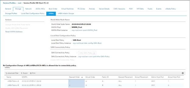
| Source | Switch/Port | WWPN/PWWN | Customer WWPN/PWWN |
| FlashStack-CT0FC2-fabricA | MDS A fc 1/1 | 52:4A:93:76:87:FF:47:00 |
|
| FlashStack-CT0FC0-fabricA | MDS A fc 1/2 | 52:4A:93:76:87:FF:47:02 |
|
| FlashStack-CT1FC2-fabricA | MDS A fc 1/3 | 52:4A:93:76:87:FF:47:10 |
|
| FlashStack-CT1FC0-fabricA | MDS A fc 1/4 | 52:4A:93:76:87:FF:47:12 |
|
| UCS Fabric Interconnect | SAN Port Channel A | 20:65:00:de:fb:07:c9:81 |
|
| VM-Host-FC-01-A | SAN Port Channel A | 20:00:00:25:b5:01:0a:08 |
|
| VM-Host-FC-02-A | SAN Port Channel A | 20:00:00:25:b5:01:0a:09 |
|
Create device alias database entries for each of the PWWNs mapping them to their human readable source names:
mds-9148s-a(config-if)# device-alias database
mds-9148s-a(config-device-alias-db)# device-alias name FlashArray-CT0FC0-fabricA pwwn 52:4A:93:76:87:FF:47:00
mds-9148s-a(config-device-alias-db)# device-alias name FlashArray-CT0FC2-fabricA pwwn 52:4A:93:76:87:FF:47:02
mds-9148s-a(config-device-alias-db)# device-alias name FlashArray-CT1FC0-fabricA pwwn 52:4A:93:76:87:FF:47:10
mds-9148s-a(config-device-alias-db)# device-alias name FlashArray-CT0FC2-fabricA pwwn 52:4A:93:76:87:FF:47:12
mds-9148s-a(config-device-alias-db)# device-alias name VM-Host-FC-01-A pwwn 20:00:00:25:b5:01:0a:08
mds-9148s-a(config-device-alias-db)# device-alias name VM-Host-FC-02-A pwwn 20:00:00:25:b5:01:0a:09
mds-9148s-a(config-device-alias-db)# exit
mds-9148s-a(config)# device-alias commit
Repeat these steps on MDS 9148S B, starting with gathering the flogi database information:
mds-9148s-b# sh flogi database
--------------------------------------------------------------------------------
INTERFACE VSAN FCID PORT NAME NODE NAME
--------------------------------------------------------------------------------
fc1/1 102 0x640200 52:4a:93:76:87:ff:47:01 52:4a:93:76:87:ff:47:01
fc1/2 102 0x640300 52:4a:93:76:87:ff:47:03 52:4a:93:76:87:ff:47:03
fc1/3 102 0x640000 52:4a:93:76:87:ff:47:11 52:4a:93:76:87:ff:47:11
fc1/4 102 0x640100 52:4a:93:76:87:ff:47:13 52:4a:93:76:87:ff:47:13
port-channel2 102 0x640400 24:02:00:de:fb:25:f1:00 20:66:00:de:fb:25:f1:01
port-channel2 102 0x640401 20:00:00:25:b5:01:0b:00 20:00:00:25:b5:01:00:00
port-channel2 102 0x640407 20:00:00:25:b5:01:0b:01 20:00:00:25:b5:01:00:01
| Source | Switch/Port | WWPN/PWWN | Customer WWPN/PWWN |
| FlashStack-CT0FC2-fabricB | MDS B fc 1/1 | 52:4A:93:76:87:FF:47:03 |
|
| FlashStack-CT0FC0-fabricB | MDS B fc 1/2 | 52:4A:93:76:87:FF:47:01 |
|
| FlashStack-CT1FC2-fabricB | MDS B fc 1/3 | 52:4A:93:76:87:FF:47:13 |
|
| FlashStack-CT1FC0-fabricB | MDS B fc 1/4 | 52:4A:93:76:87:FF:47:11 |
|
| UCS Fabric Interconnect | SAN Port Channel B | 24:02:00:de:fb:25:f1:00 |
|
| VM-Host-FC-01-B | SAN Port Channel B | 20:00:00:25:b5:01:0b:08 |
|
| VM-Host-FC-02-B | SAN Port Channel B | 20:00:00:25:b5:01:0b:09 |
|
Create device alias database entries for each of the PWWNs mapping them to their human readable source names:
mds-9148s-b(config-if)# device-alias database
mds-9148s-b(config-device-alias-db)# device-alias name FlashArray-CT0FC1-fabricB pwwn 52:4A:93:76:87:FF:47:01
mds-9148s-b(config-device-alias-db)# device-alias name FlashArray-CT0FC3-fabricB pwwn 52:4A:93:76:87:FF:47:03
mds-9148s-b(config-device-alias-db)# device-alias name FlashArray-CT1FC1-fabricB pwwn 52:4A:93:76:87:FF:47:11
mds-9148s-b(config-device-alias-db)# device-alias name FlashArray-CT1FC3-fabricB pwwn 52:4A:93:76:87:FF:47:13
mds-9148s-b(config-device-alias-db)# device-alias name VM-Host-FC-01-B pwwn 20:00:00:25:b5:01:0b:08
mds-9148s-b(config-device-alias-db)# device-alias name VM-Host-FC-02-B pwwn 20:00:00:25:b5:01:0b:09
mds-9148s-b(config-device-alias-db)# exit
mds-9148s-b(config)# device-alias commit
MDS VSAN Zoning
Create zones for each host using the device aliases created in the previous step, specifying init and target roles to optimize zone traffic:
Zone for UCS VM-Host-FC-01 on MDS A
mds-9148s-a(config)# zone name VM-Host-FC-01-A vsan 101
mds-9148s-a(config-zone)# member device-alias VM-Host-FC-01-A init
mds-9148s-a(config-zone)# member device-alias FlashArray-CT0FC0-fabricA target
mds-9148s-a(config-zone)# member device-alias FlashArray-CT0FC2-fabricA target
mds-9148s-a(config-zone)# member device-alias FlashArray-CT1FC0-fabricA target
mds-9148s-a(config-zone)# member device-alias FlashArray-CT1FC2-fabricA target
Zone for UCS VM-Host-FC-02 on MDS A
mds-9148s-a(config-zone)# zone name VM-Host-FC-02-A vsan 101
mds-9148s-a(config-zone)# member device-alias VM-Host-FC-02-A init
mds-9148s-a(config-zone)# member device-alias FlashArray-CT0FC0-fabricA target
mds-9148s-a(config-zone)# member device-alias FlashArray-CT0FC2-fabricA target
mds-9148s-a(config-zone)# member device-alias FlashArray-CT1FC0-fabricA target
mds-9148s-a(config-zone)# member device-alias FlashArray-CT1FC2-fabricA target
Zone for UCS VM-Host-FC-01 on MDS B
mds-9148s-b(config)# zone name VM-Host-FC-01-B vsan 102
mds-9148s-b(config-zone)# member device-alias VM-Host-FC-01-B init
mds-9148s-b(config-zone)# member device-alias FlashArray-CT0FC1-fabricB target
mds-9148s-b(config-zone)# member device-alias FlashArray-CT0FC3-fabricB target
mds-9148s-b(config-zone)# member device-alias FlashArray-CT1FC1-fabricB target
mds-9148s-b(config-zone)# member device-alias FlashArray-CT1FC3-fabricB target
Zone for UCS VM-Host-FC-02 on MDS B
mds-9148s-b(config)# zone name VM-Host-FC-02-B vsan 102
mds-9148s-b(config-zone)# member device-alias VM-Host-FC-02-B init
mds-9148s-b(config-zone)# member device-alias FlashArray-CT0FC1-fabricB target
mds-9148s-b(config-zone)# member device-alias FlashArray-CT0FC3-fabricB target
mds-9148s-b(config-zone)# member device-alias FlashArray-CT1FC1-fabricB target
mds-9148s-b(config-zone)# member device-alias FlashArray-CT1FC3-fabricB target
Repeating these steps on each MDS for each Cisco UCS host provisioned.
Add zones to the zoneset
Add the zones to a zoneset on each MDS switch:
zoneset for MDS A
mds-9148s-a(config-zone)# zoneset name flashstack-zoneset vsan 101
mds-9148s-a(config-zoneset)# member VM-Host-FC-01-A
mds-9148s-a(config-zoneset)# member VM-Host-FC-02-A
zoneset for MDS B
mds-9148s-b(config-zone)# zoneset name flashstack-zoneset vsan 102
mds-9148s-b(config-zoneset)# member VM-Host-FC-01-B
mds-9148s-b(config-zoneset)# member VM-Host-FC-02-B
Activate the zonesets and save the configuration:
zoneset for MDS A
mds-9148s-a(config-zoneset)# zoneset activate name flashstack-zoneset vsan 101
mds-9148s-a(config)# copy run start
zoneset for MDS B
mds-9148s-b(config-zoneset)# zoneset activate name flashstack-zoneset vsan 102
mds-9148s-b(config)# copy run start
The Pure Storage FlashArray//X is accessible to the FlashStack, but no storage has been deployed at this point. The storage to be deployed will include:
· ESXi Fibre Channel Boot LUNs
· VMFS Datastores
The FC Boot LUNs will need to be setup from the Pure Storage Web Portal, but the VMFS datastores can be directly provisioned from the vSphere Web Client after the Pure Storage vSphere Web Client Plugin has later on been registered with the vCenter.
Figure 7 FlashArray//X Storage Deployment Workflow
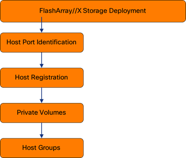
Host Registration
For Host registration, complete the following steps:
1. Host entries can be made from the Pure Storage Web Portal from the STORAGE tab, by selecting the + box next to Hosts appearing in the left side column:
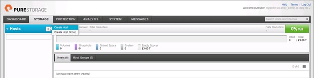
2. After clicking the Create Host option, a pop-up will appear to create an individual host entry on the FlashArray:
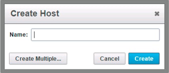
3. To create more than one host entry, click the Create Multiple… option, filling in the Name, Start Number, Count, and Number of Digits, with a “#” appearing in the name where an iterating number will appear:
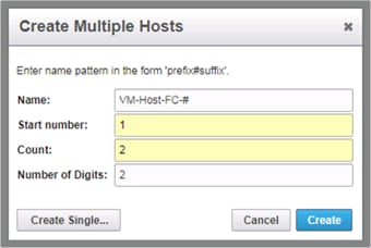
4. Click Create to add the hosts.
5. For each host created, select the host from within the STORAGE tab, and click the Host Ports tab within the individual host view. From the Host Ports tab select the gear icon drop-down and select Configure Fibre Channel WWNs:
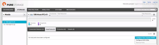
6. A pop-up will appear for Configure Fibre Channel WWNs for Host <host being configured>. Within this pop-up, click the Enter WWNs Manually button and enter in the WWNs (WWPN) for each host previously recorded in Table 16 and Table 17:
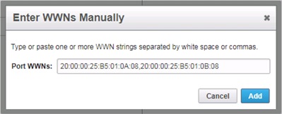
7. After adding the WWNs, click Confirm to add the Host Ports. Repeat these steps for each host created.
Private Volumes for each ESXi Host
To create private volumes for each ESXi host, complete the following steps:
1. Volumes can be provisioned from the Pure Storage Web Portal from the STORAGE tab, by clicking the + box next to Volumes appearing in the left side column:
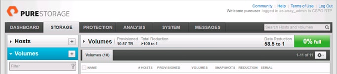
2. A pop-up will appear to create a volume on the FlashArray:
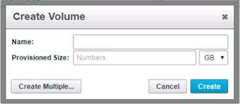
3. To create more than one volume, click the Create Multiple… option, filling in the Name, Provisioned Size, Staring Number, Count, and Number of Digits, with a “#” appearing in the name where an iterating number will appear:
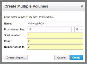
4. Click Create to provision the volumes to be used as FC boot LUNs.
5. Go back to the Hosts section under the STORAGE tab. Click one of the hosts and select the gear icon drop-down within the Connected Volumes tab within that host.
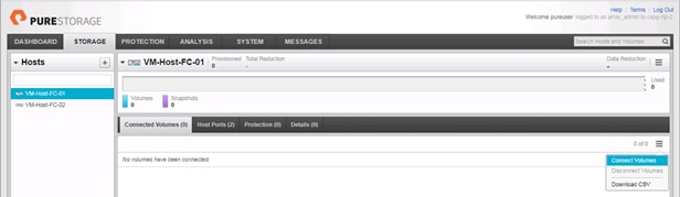
6. Within the drop-down of the gear icon, select Connect Volumes, and a pop-up will appear:
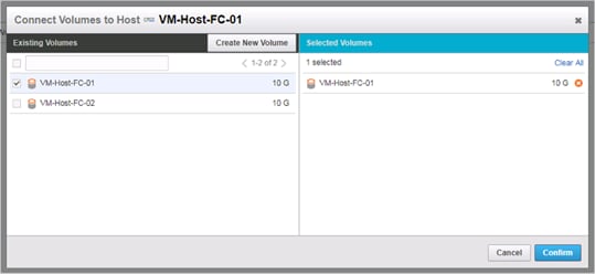
7. Select the volume that has been provisioned for the host, click the + next to the volume and select Confirm to proceed. Repeat the steps for connecting volumes for each of the host/volume pairs configured.
Host Groups
The Host entries allow for the individual boot LUNs to associate to each ESXi host, but the shared volumes to use as VM datastores need Host Groups to have those volumes shared amongst multiple hosts.
To create a Host Group in the Pure Storage Web Portal, complete the following steps:
1. Select the STORAGE tab and click the + box next to Hosts appearing in the left side column:
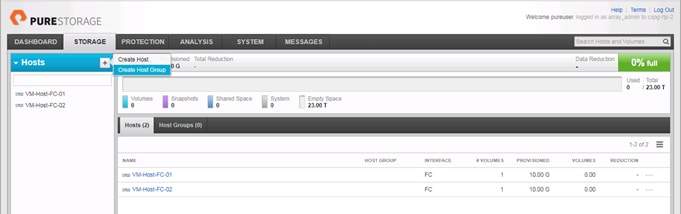
2. Select the Create Host Group option and provide a name for the Host Group to be used by the ESXi cluster:
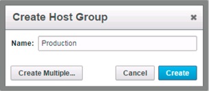
3. With Hosts still selected within the STORAGE tab, click the gear icon drop-down within the Hosts tab of the Host Group created, and select Add Hosts:
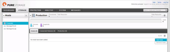
4. Select the + icon next to each host and click Confirm to add them to the Host Group:
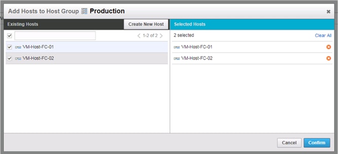
ESXi Installation
This section provides detailed instructions to install VMware ESXi 6.5 U1 in a FlashStack environment. After these procedures are completed, FC booted ESXi hosts will be configured.
Figure 8 vSphere Deployment Workflow
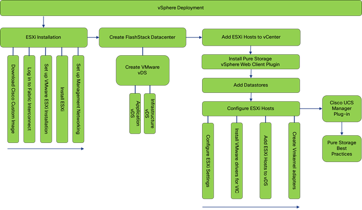
Several methods exist for installing ESXi in a VMware environment. These procedures focus on how to use the built-in keyboard, video, mouse (KVM) console and virtual media features in Cisco UCS Manager to map remote installation media to individual servers and connect to their boot logical unit numbers (LUNs).
Download Cisco Custom Image for ESXi 6.5 U1
The VMware Cisco Custom Image will be needed for use during installation by manual access to the UCS KVM vMedia, or through a vMedia Policy covered in a previous subsection. If the Cisco Custom Image was not downloaded during the vMedia Policy setup, download it now by completing the following steps:
1. Click the following link: VMware vSphere Hypervisor Cisco Custom Image (ESXi) 6.5 U1.
2. You will need a user id and password on vmware.com to download this software.
3. Download the .iso file.
Log in to Cisco UCS 6332-16UP Fabric Interconnect
The IP KVM enables the administrator to begin the installation of the operating system (OS) through remote media. It is necessary to log in to the UCS environment to run the IP KVM.
To log in to the Cisco UCS environment, complete the following steps:
1. Open a web browser to https:// <<var_ucs_mgmt_vip>>
2. Select the Launch UCS Manager Section in the HTML section to pull up the UCSM HTML5 GUI.
3. Enter admin for the Username, and provide the password used during setup.
4. Within the UCSM select Servers -> Service Profiles, and pick the first host provisioned, which should be named VM-Host-FC-01.
5. Click the KVM Console option within Actions, and accept the KVM server certificate in the new window or browser tab that is spawned for the KVM session.
6. Click the link within the new window or browser tab to load the KVM client application.
Set Up VMware ESXi Installation
![]() Skip this step if you are using vMedia policies. ISO file will already be connected to KVM.
Skip this step if you are using vMedia policies. ISO file will already be connected to KVM.
To prepare the server for the OS installation, complete the following steps on each ESXi host:
1. In the KVM window, click Virtual Media icon ![]() in the upper right of the screen.
in the upper right of the screen.
2. Click Activate Virtual Devices
3. Click Virtual Media again and select Map CD/DVD.
4. Browse to the ESXi installer ISO image file and click Open.
5. Click Map Device.
6. Click the KVM tab to monitor the server boot.
7. Boot the server by selecting Boot Server and clicking OK, then click OK again.
Install ESXi
To install VMware ESXi to the FC bootable LUN of the hosts, complete the following steps on each host:
1. On reboot, the machine detects the presence of the ESXi installation media. Select the ESXi installer from the boot menu that is displayed.
2. After the installer is finished loading, press Enter to continue with the installation.
3. Read and accept the end-user license agreement (EULA). Press F11 to accept and continue.
4. Select the LUN that was previously set up as the installation disk for ESXi and press Enter to continue with the installation.
5. Select the appropriate keyboard layout and press Enter.
6. Enter and confirm the root password and press Enter.
7. The installer issues a warning that the selected disk will be repartitioned. Press F11 to continue with the installation.
8. After the installation is complete, if using locally mapped Virtual Media, click the Virtual Media tab and clear the checkmark next to the ESXi installation media. Click Yes.
![]() The ESXi installation image must be unmapped to make sure that the server reboots into ESXi and not into the installer. If using a vMedia Policy, this will be unnecessary as the vMedia will appear after the installed OS.
The ESXi installation image must be unmapped to make sure that the server reboots into ESXi and not into the installer. If using a vMedia Policy, this will be unnecessary as the vMedia will appear after the installed OS.
9. From the KVM window, press Enter to reboot the server.
Set Up Management Networking for ESXi Hosts
Adding a management network for each VMware host is necessary for managing the host. To add a management network for the VMware hosts, complete the following steps on each ESXi host:
1. After the server has finished rebooting, press F2 to customize the system.
2. Log in as root, enter the corresponding password, and press Enter to log in.
3. Select the Configure the Management Network option and press Enter.
4. Select Network Adapters option leave vmnic0 selected, arrow down to vmnic1 and press space to select vmnic1 as well and press Enter.
5. Select the VLAN (Optional) option and press Enter.
6. Enter the <<var_ib_mgmt_vlan_id>> and press Enter.
7. From the Configure Management Network menu, select IPv4 Configuration and press Enter.
8. Select the Set Static IP Address and Network Configuration option by using the space bar.
9. Enter <<var_vm_host_infra_01_ip>> for the IPv4 Address for managing the first ESXi host.
10. Enter <<var_ib_mgmt_vlan_netmask_length>> for the Subnet Mask for the first ESXi host.
11. Enter <<var_ib_mgmt_gateway>> for the Default Gateway for the first ESXi host.
12. Press Enter to accept the changes to the IPv4 configuration.
13. Select the DNS Configuration option and press Enter.
![]() Because the IP address is assigned manually, the DNS information must also be entered manually.
Because the IP address is assigned manually, the DNS information must also be entered manually.
14. Enter the IP address of <<var_nameserver_ip>> for the Primary DNS Server.
15. Optional: Enter the IP address of the Secondary DNS Server.
16. Enter the fully qualified domain name (FQDN) for the first ESXi host.
17. Press Enter to accept the changes to the DNS configuration.
18. Select the IPv6 Configuration option and press Enter.
19. Using the spacebar, select Disable IPv6 (restart required) and press Enter.
20. Press Esc to exit the Configure Management Network submenu.
21. Press Y to confirm the changes and return to the main menu.
22. The ESXi host reboots. After reboot, press F2 and log back in as root.
23. Select Test Management Network to verify that the management network is set up correctly and press Enter.
24. Press Enter to run the test.
25. Press Enter to exit the window, and press Esc to log out of the VMware console.
26. Repeat steps 1-47 for additional hosts provisioned, using appropriate values.
Create FlashStack Datacenter
If a new Datacenter is needed for the FlashStack, complete the following steps on the vCenter:
1. Connect to the vSphere Web Client and click Hosts and Clusters from the left side Navigator window, or the Hosts and Clusters icon from the Home center window.
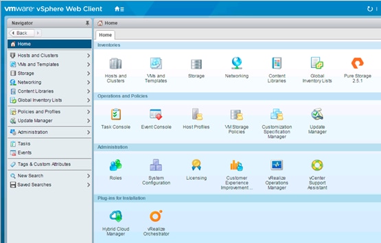
2. Right-click the vCenter icon and select New Datacenter… from the drop-down options.
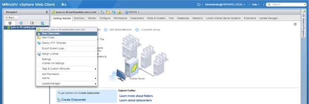
3. From the New Datacenter pop-up dialogue enter in a Datacenter name and click OK.
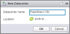
Create VMware vDS for Infrastructure and Application Traffic
The VMware vDS setup will consist of two vDS that are separated for Infrastructure use versus Application traffic.
FlashStack Infrastructure vDS
To configure the first VMware vDS, complete the following steps:
1. Connect to the vSphere Web Client and click Networking from the left side Navigator window, or the Networking icon from the Home center window.
2. Right-click the FlashStack-VSI datacenter and select Distributed Switch > New Distributed Switch…
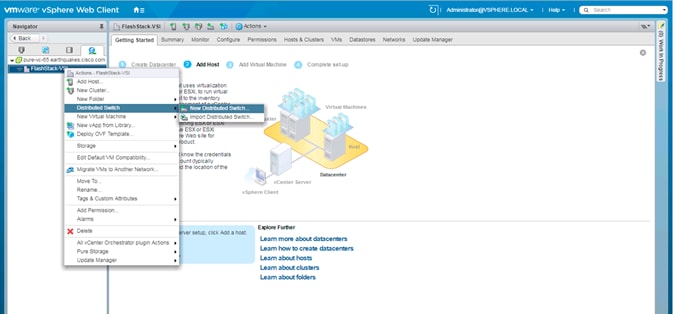
3. Give the Distributed Switch a descriptive name and click Next.
4. Make sure Distributed switch: 6.5.0 is selected and click Next.
5. Leave the Number of uplinks at 4. If VMware Network I/O Control is to be used for Quality of Service, leave Network I/O Control Enabled. Otherwise, Disable Network I/O Control. Enter IB-Mgmt for the name of the default Port group to be created. Click Next.
6. Review the information and click Finish to complete creating the vDS.

7. Right-click the newly created vDS on the left, and select Settings -> Edit Settings…
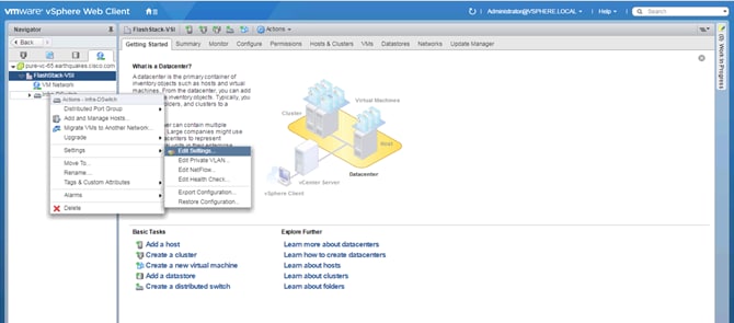
8. Click the Advanced option on the left side of the Edit Settings window, and adjust the MTU from 1500 to 9000.
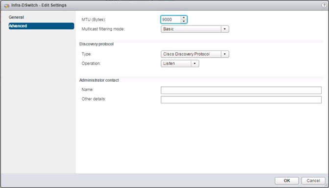
9. Click OK to save the changes.
10. On the left, expand the FlashStack VSI datacenter and the newly created vDS.
11. Right-click the IB-Mgmt Distributed Port Group, and select Edit Settings…
12. Click VLAN, changing VLAN type from None to VLAN, and enter in the appropriate VLAN number for the IB-Mgmt network.
13. Click the Teaming and Failover and move the Uplinks 3 and 4 to the Unused uplinks state, and move the Uplink 2 to the Standby uplinks state.
![]() Movement of Uplink 2 to standby is guiding Management traffic to stay within the A side fabric contained within Uplink 1 to prevent unnecessary traffic hops up into the Nexus switch to traverse between fabrics. Uplinks 3 and 4 are set as unused as these are the vMotion vNICs and will be used by the other Distributed Port Group in this vDS.
Movement of Uplink 2 to standby is guiding Management traffic to stay within the A side fabric contained within Uplink 1 to prevent unnecessary traffic hops up into the Nexus switch to traverse between fabrics. Uplinks 3 and 4 are set as unused as these are the vMotion vNICs and will be used by the other Distributed Port Group in this vDS.
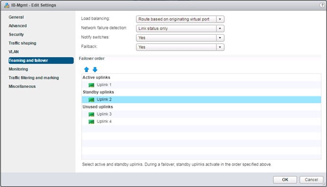
14. Click OK to save the changes.
15. Right-click the infrastructure vDS (Infra-DSwitch), and select Distributed Port Group -> New Distributed Port Group…
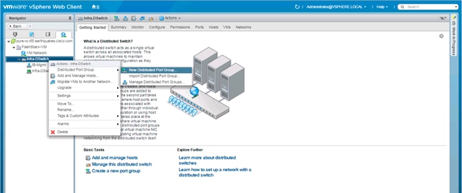
16. Name the new Port Group vMotion and click Next.
17. Change the VLAN type from None to VLAN, select the VLAN ID appropriate for your vMotion traffic, and select the Customize default policies configuration check box under the Advanced section.
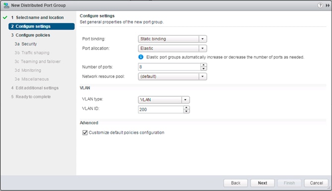
18. Click Next.
19. Click Next through the Security and Traffic Shaping sections.
20. Within the Teaming and failover section, move Uplinks 1 and 2 to the Unused uplinks section, and move Uplink 3 to the Standby uplinks section.
![]() Teaming for the vMotion Distributed Port Group will be a mirror of teaming on the Infrastructure Distributed Port group. Uplinks 1 and 2 are unused because they are used by the Infrastructure Distributed Port group, and Uplink 3 will be moved to standby to guide vMotion traffic to stay within the B side fabric contained within Uplink 4.
Teaming for the vMotion Distributed Port Group will be a mirror of teaming on the Infrastructure Distributed Port group. Uplinks 1 and 2 are unused because they are used by the Infrastructure Distributed Port group, and Uplink 3 will be moved to standby to guide vMotion traffic to stay within the B side fabric contained within Uplink 4.
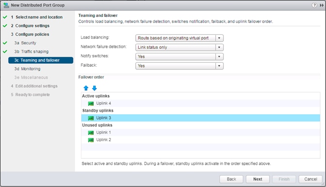
21. Click Next.
22. Click Next past Monitoring, Miscellaneous, and click Edit additional settings sections.
23. Review the Ready to complete section.
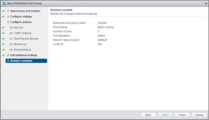
24. Click Finish to create the Distributed Port Group.
FlashStack Application vDS
To configure the second VMware vDS, complete the following steps:
1. Right-click the FlashStack-VSI Datacenter and select Distributed Switch -> New Distributed Switch… to create the Application vDS.
2. Provide a name for the vDS (App-DSwitch), and click Next.
3. Make sure Distributed switch: 6.5.0 is selected and click Next.
4. Change the Number of uplinks to 2. If VMware Network I/O Control is to be used for Quality of Service, leave Network I/O Control Enabled. Otherwise, Disable Network I/O Control. Enter App-201 for the name of the default Port group to be created. Click Next.
5. Review the information and click Finish to complete creating the vDS.
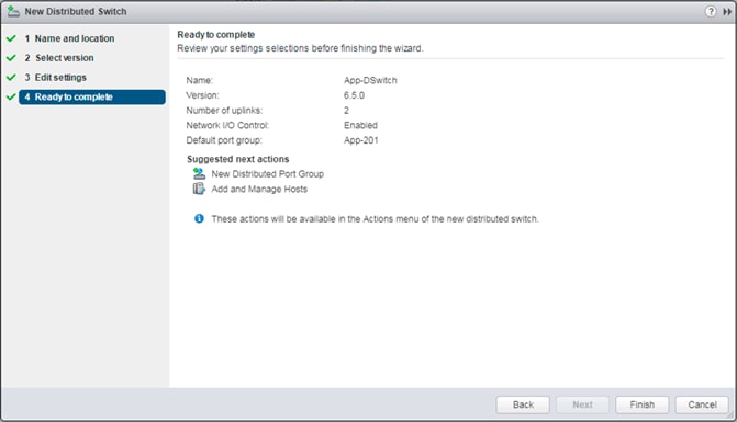
6. Right-click the newly created App-DSwitch vDS, and select Settings -> Edit Settings…
7. Click the Advanced option for the Edit Settings window and change the MTU from 1500 to 9000.
8. Click OK to save the changes.
9. Right-click the App-201 Distributed Port Group, and select Edit Settings…
10. Click VLAN, changing VLAN type from None to VLAN, and enter in the appropriate VLAN number for the first application network.
![]() The application Distributed Port Groups will not need to adjust their NIC Teaming as they will be Active/Active within the two vNICs uplinks associated to the App-DSwitch, using the default VMware Route based on originating virtual port load balancing algorithm.
The application Distributed Port Groups will not need to adjust their NIC Teaming as they will be Active/Active within the two vNICs uplinks associated to the App-DSwitch, using the default VMware Route based on originating virtual port load balancing algorithm.
11. Click OK to save the changes.
12. Right-Click the App-DSwitch, selecting Distributed Port Group -> New Distributed Port Group… for any additional application networks to be created, setting the appropriate VLAN for each new Distributed Port Group.
Add the VMware ESXi Hosts Using the VMware vSphere Web Client
To add the VMware ESXi Hosts using the VMware vSphere Web Client, complete the following steps:
1. From the Hosts and Clusters tab, right-click the new or existing Datacenter within the Navigation window, and select New Cluster… from the drop-down options.
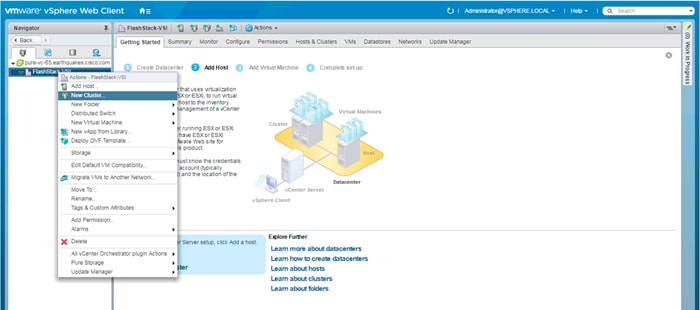
2. Enter a name for the new cluster, select the DRS and HA check mark boxes, leaving all other options with defaults.
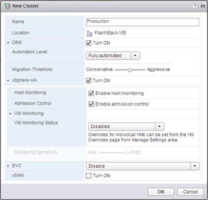
3. Click OK to create the cluster.
4. Right-click the newly created cluster and select the Add Host… drop-down option.
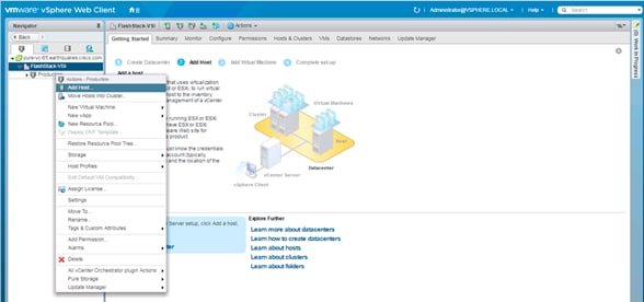
5. Enter the IP or FQDN of the first ESXi host and click Next.
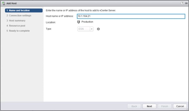
6. Enter root for the User Name, provide the password set during initial setup, and click Next.
7. Click Yes in the Security Alert pop-up to confirm the host’s certificate.
8. Click Next past the Host summary dialogue.
9. Provide a license by clicking the green + icon under the License title, select an existing license, or skip past the Assign license dialogue by clicking Next.
10. Leave lockdown mode Disabled within the Lockdown mode dialogue window, and click Next.
11. Skip past the Resource pool dialogue by clicking Next.
12. Confirm the Summary dialogue and add the ESXi host to the cluster by clicking Next.
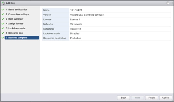
13. Repeat these steps for each ESXi host to be added to the cluster.
Pure Storage vSphere Web Client Plugin
The Pure Storage vSphere Web Client Plugin will be accessible through the vSphere Web Client after registration through the Pure Storage Web Portal.
![]() The Purity 4.10.5 release comes with the 2.5.1 version of the plugin, which will work, but will not allow provisioning of VMFS-6 datastores. The example below shows an early release of the 3.0 plugin, which can be installed to the FlashArray by submitting a support request with Pure Support asking for the plugin upgrade. This is not a requirement, but in the absence of the upgraded plugin, LUNs would need to be manually provisioned through the Purity Web Console, and VMFS-6 datastore would be created from the LUNs within vCenter.
The Purity 4.10.5 release comes with the 2.5.1 version of the plugin, which will work, but will not allow provisioning of VMFS-6 datastores. The example below shows an early release of the 3.0 plugin, which can be installed to the FlashArray by submitting a support request with Pure Support asking for the plugin upgrade. This is not a requirement, but in the absence of the upgraded plugin, LUNs would need to be manually provisioned through the Purity Web Console, and VMFS-6 datastore would be created from the LUNs within vCenter.
The vCenter server for this environment should be in place on an independent management cluster that is accessible to the In-Band management network the ESXi hosts will be deployed to.
If a new dedicated vCenter server is required for your environment, please follow the instructions from VMware found at: https://docs.vmware.com/en/VMware-vSphere/6.5/vsphere-esxi-vcenter-server-65-installation-setup-guide.pdf.
To access the Pure Storage vSphere Web Client Plugin, complete the following steps:
1. Go to System -> Plugins -> vSphere:
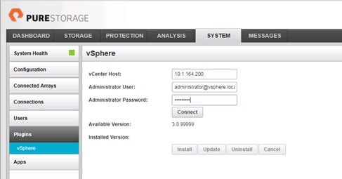
2. Enter the vCenter Host IP or FQDN, the Administrator User to connect with, the password for the Administrator User, and click Connect. Once connected, select the Install button to register the plugin.
3. With the plugin registered, connect to the vSphere Web Client and select the Pure Storage Plugin from the Home page:
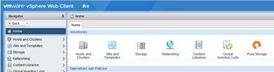
4. Click Add FlashArray within the options under the Object tab.
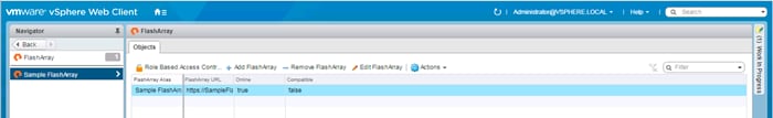
![]() The Sample FlashArray entry can optionally be removed.
The Sample FlashArray entry can optionally be removed.
5. Enter the FlashArray Name, FlashArray URL, Username and Password in the Add FlashArray pop-up window.
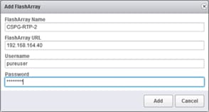
6. Click Add to register the FlashArray//X within the plugin.
Add Datastores
These next steps add a datastore to place VMs on the FlashArray//X and optionally a second datastore for keeping their swapfiles.
![]() A dedicated swapfile location will not provide a performance increase over the existing all flash datastores created from the FlashArray//X, but can be useful to have these files in a separate location to have them excluded from snapshots and backups.
A dedicated swapfile location will not provide a performance increase over the existing all flash datastores created from the FlashArray//X, but can be useful to have these files in a separate location to have them excluded from snapshots and backups.
1. Right-click the cluster and select the Pure Storage -> Create Datastore option from the drop-down.
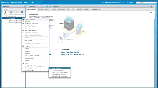
2. Give the Datastore Name a value appropriate for VM store in the environment, select a starting size for the Datastore Size, click the VMFS 6 selection under VMFS Options, and click Create to provision the volume.
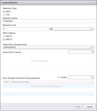
3. Optionally, repeat these similar steps to create a swap datastore to be used by the ESXi hosts. Right-click the cluster and select the Pure Storage -> Create Datastore option from the drop-down.
4. Give the Datastore Name a value appropriate for VM swapfiles on the ESXi host, select a starting size for the Datastore Size, click the VMFS 6 selection under VMFS Options, and click Create to provision the volume.
Configure ESXi Hosts in the Cluster
Configure ESXi Settings
A couple of base settings are needed for stability of the vSphere environment, as well as optional enablement of SSH connectivity to each host for the updating of drivers.
To configure ESXi settings, complete the following steps:
1. Select the first ESXi host to configure with standard settings.
2. Select the Configure tab and select Time Configuration within the options on the left under System, and click Edit within Time Configuration.
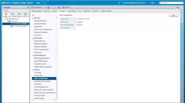
3. Select Use Network Time Protocol (Enable NTP client), enter <<var_nexus_A_ib_ip>>, <<var_nexus_A_ib_ip>> for the NTP Servers, select Start and stop with host for NTP Service Startup Policy, and click Start within NTP Service Status. Click OK to submit the changes.
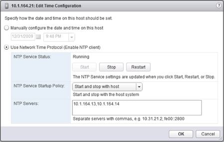
4. (Optional) Click Security Profile within the Configure tab under the System section for the host.
![]() Security Profile settings of ESXi Shell and SSH are enabled for the potential update of the nenic and fnic drivers later. These steps are unnecessary if using VMware Update Manager and these drivers are being handled by being included into a configured baseline. If SSH is enabled for updates, it is recommended to later disable this service if it is considered a security risk in the environment.
Security Profile settings of ESXi Shell and SSH are enabled for the potential update of the nenic and fnic drivers later. These steps are unnecessary if using VMware Update Manager and these drivers are being handled by being included into a configured baseline. If SSH is enabled for updates, it is recommended to later disable this service if it is considered a security risk in the environment.
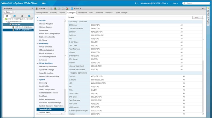
5. Scroll down to the Services section within Security Profile and click the Edit button.
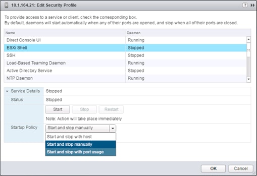
6. Select the ESXi Shell entry, change the Startup Policy to Start and stop with port usage, and click Start. Repeat these steps for the SSH entry. Click OK.

7. If an optional ESXi swap datastore was configured earlier, click System Swap the System section within the Configure tab and click Edit.
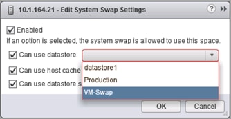
8. Checkmark the Can use datastore option, and from the drop-down select the ESXi swap datastore that was configured. Click OK.
9. Repeat these steps on each ESXi host being added into the cluster.
Install VMware Driver for the Cisco Virtual Interface Card (VIC)
The Cisco Custom Image for VMware vSphere 6.5 U1 comes with the currently specified fnic 1.6.0.34 and the nenic 1.0.6.0 for fibre channel and Ethernet traffic from the ESXi host, so neither will require updating at this time. For the most recent versions, please refer to Cisco UCS HW and SW Availability Interoperability Matrix. If a more recent driver is made available that is appropriate for VMware vSphere 6.5 U1, the following is an example of the steps that can be followed to update the drivers.
To install VMware VIC Drivers on the ESXi hosts, complete the following steps:
1. Download and extract either driver bundle (example nenic Driver version 1.0.6.0) to the system the vSphere Web Client is running from.
2. Within the vSphere Web Client, select one of the datastores common to all of the hosts.
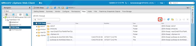
3. Click the Upload a file to the Datastore button.
4. Select and upload the offline_bundle (VMW-ESX-6.5.0-nenic-1.0.6.0-offline_bundle-5894048.zip) from each of the extracted driver downloads.
5. Place all hosts in Maintenance mode requiring update.
6. Connect to each ESXi host through ssh from a shell connection or putty terminal.
7. Login as root with the root password.
8. Run the following command (substituting the appropriate datastore directory if needed) on each host:
esxcli software vib update -d /vmfs/volumes/ESXi-Swap/VMW-ESX-6.5.0-nenic-1.0.6.0-offline_bundle-5894048.zip
9. Reboot each host by typing reboot from the SSH connection after the command has been run.
10. Log into the Host Client on each host once reboot is complete.
Add the ESXi hosts to the vDS
To Add the ESXi Hosts to each vDS, complete the following steps:
1. Within the Networking tab of the Navigator window, right-click the Infra-DSwitch vDS and select Add and Manage Hosts…

2. Leave Add hosts selected and click Next.
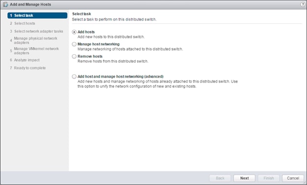
3. Click the green + icon next to New hosts…
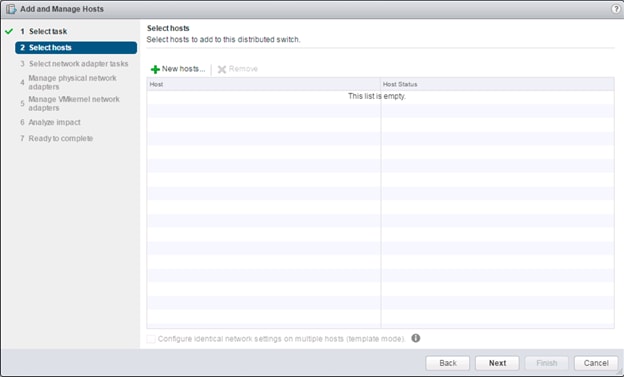
4. In the Select new hosts pop-up that appears, select the hosts to be added, and click OK to begin joining them to the vDS.

5. Click Next.
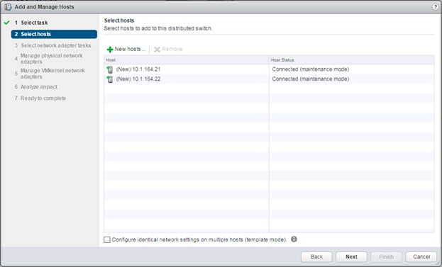
6. Leave Manage physical adapters and Manage VMkernel adapters both selected and click Next.
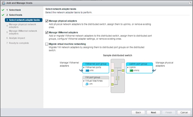
7. Select vmnic0 from the Host/Physical Network Adapters column and click the Assign uplink option.
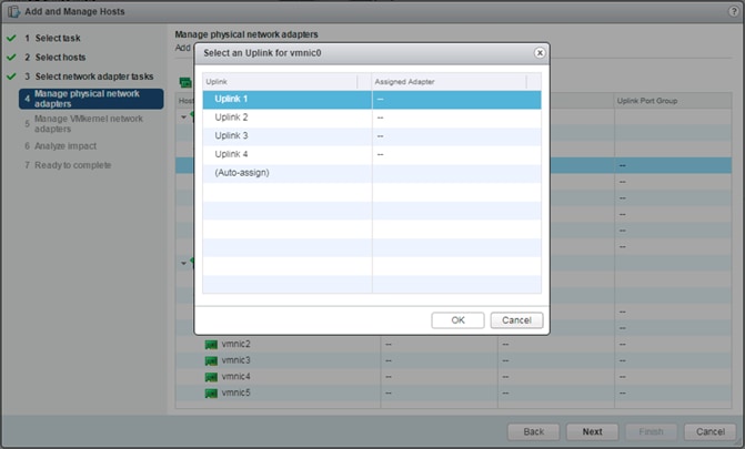
8. Leave Uplink 1 selected and click OK.
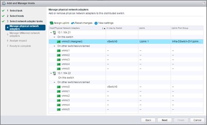
9. Repeat this step for vmnic1-3, assigning them to uplinks 2-4 in corresponding sequence.
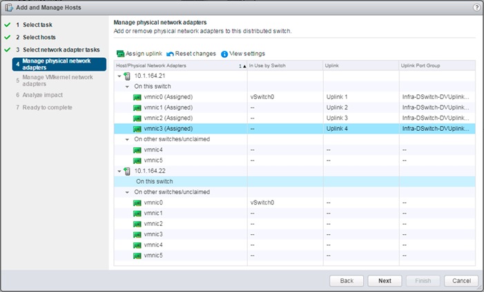
10. Repeat these assignment for all additional ESXi hosts being configured.
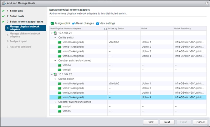
11. Click Next.
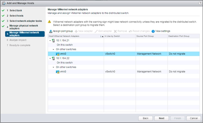
12. Select the vmk0 of the first host and click the Assign port group option.
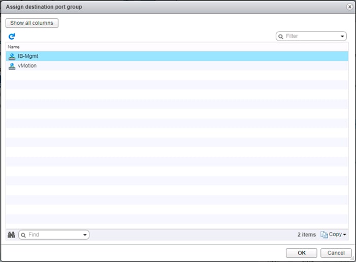
13. Select the IB-Mgmt destination port group and click OK.
14. Repeat this step for all additional hosts being configured.
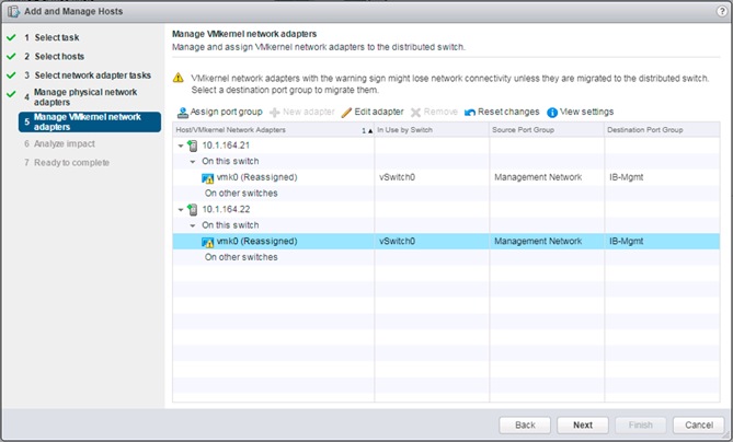
15. Click Next.
16. Click Next past Analyze impact.
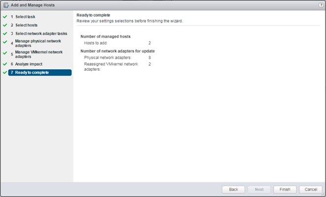
17. Review the settings and click Finish to apply.
18. Similar to the steps followed for adding the Infra-DSwitch vDS, within the Networking tab of the Navigator window, right-click the App-DSwitch vDS and select Add and Manage Hosts…
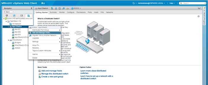
19. Leave Add hosts selected and click Next.
20. Click the green + icon next to New hosts…
21. In the Select new hosts pop-up that appears, select the hosts to be added, and click OK to begin joining them to the vDS.
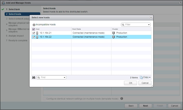
22. Click Next.
23. Leave Manage physical adapters selected and unselect Manage VMkernel adapters.
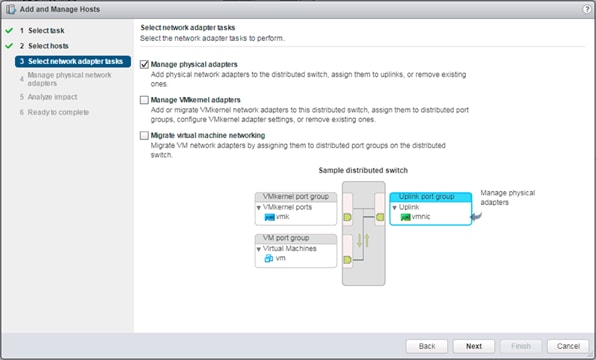
24. Click Next.
25. Select vmnic4 from the Host/Physical Network Adapters column and click the Assign uplink option.
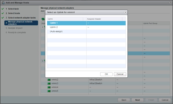
26. Leave Uplink 1 selected and click OK.
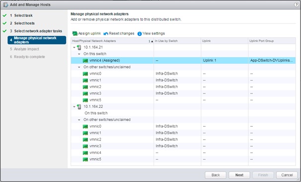
27. Repeat this step for vmnic5, assigning it to uplink 2, then perform these same steps for vmnic4 and vmnic5 for all remaining ESXi hosts to be configured.
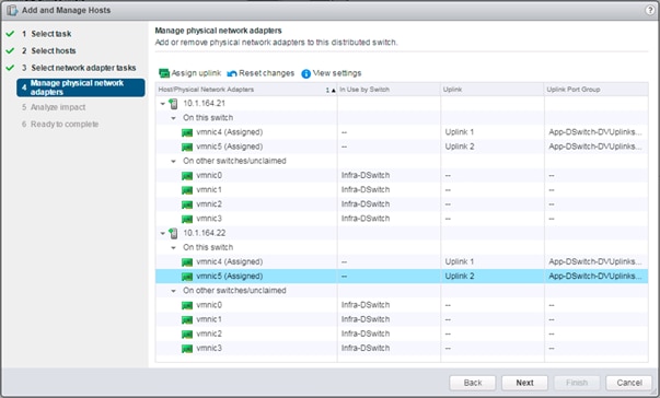
28. Click Next.
29. Click Next past Analyze impact.
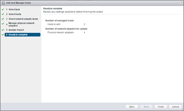
30. Review the settings and click Finish to apply.
Create vMotion VMkernel adapters
A vMotion VMkernel adapter will be created for FlashStack infrastructure to keep vMotion traffic independent of management traffic. To create the vMotion VMKernel adapters, perform the following steps:
1. From the Hosts and Clusters, drill down to the first host and select the Configure tab for that host.
2. Select the VMkernel adapters option within the Networking section of Configure.
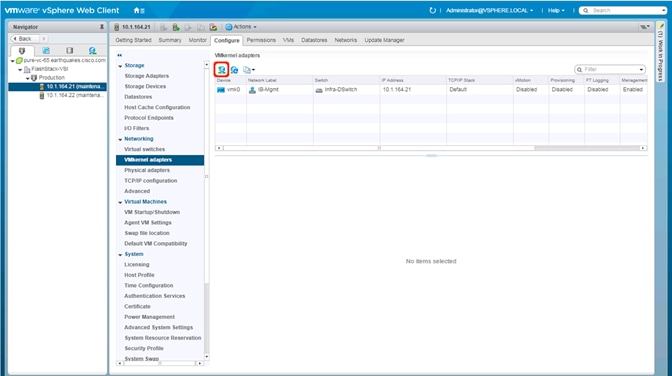
3. Click the first icon under VMkernel adapters to Add host networking.
4. Leave the connection type selected as VMkernel Network Adapter and click Next.
5. Select Browse with Select an existing network selected.
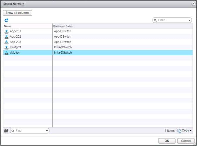
6. Pick the vMotion network from the list shown and click OK.
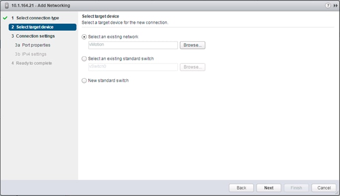
7. Click Next.
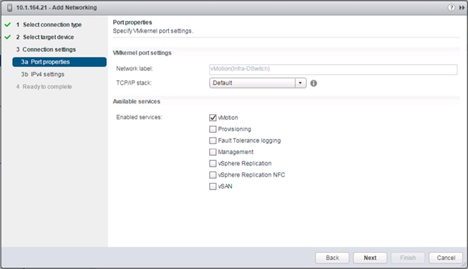
8. Select the vMotion from the Available services and click Next.
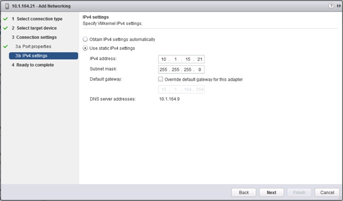
9. Provide and IP address and subnet mask within the vMotion network. Click Next.
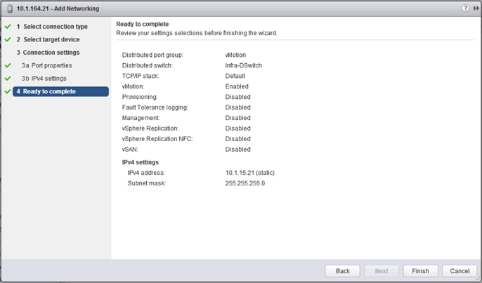
10. Review the settings and click Finish to create the VMkernel adapter.
11. Select the newly created vMotion VMkernel adapter.
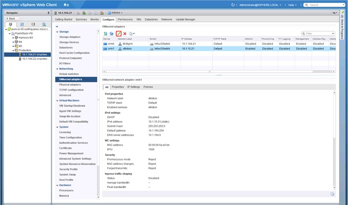
12. Click the pencil icon to Edit settings for the VMkernel adapter.
13. Select the NIC Settings option and change the MTU from 1500 to 9000.
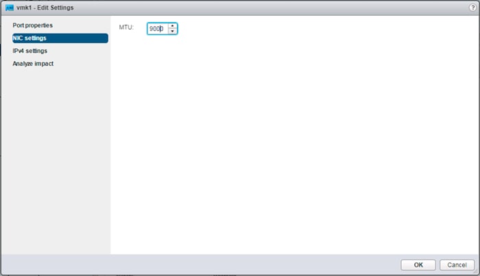
14. Click OK to save the changes.
15. Repeat these steps to create and adjust vMotion VMkernel adapters for each additional ESXi host.
Cisco UCS Manager Plug-in for VMware vSphere Web Client
The Cisco UCS Manager Plug-in for VMware vSphere Web Client allows administration of UCS domains through the VMware’s vCenter administrative interface. The capabilities of the plug-in include:
· View Cisco UCS physical hierarchy
· View inventory, installed firmware, faults, power and temperature statistics
· Map the ESXi host to the physical server
· Manage firmware for Cisco UCS B and C series servers
· Launch the Cisco UCS Manager GUI
· Launch the KVM consoles of UCS servers
· Switch the existing state of the locator LEDs
The installation is only valid for VMware vCenter 5.5 or higher, and will require revisions of .NET Framework 4.5 and VMware PowerCLI 5.1 or greater.
Cisco UCS Manager Plug-in Installation
To begin the plug-in installation on a Windows system that meets the previously stated requirements, complete the following steps:
1. Download the plugin and registration tool from: https://software.cisco.com/download/release.html?mdfid=286282669&catid=282558030&softwareid=286282010&release=2.0.3
2. Place the downloaded ucs-vcplugin-2.0.3.zip file on an accessible web server previously used for hosting the VMware ESXi ISO.
3. Extract the Cisco_UCS_Plugin_Registration_Tool_1_1_3.zip and open the executable file within it.
4. Leave Register Plugin selected for the Action, and fill in:
a. IP/Hostname
b. Username
c. Password
d. URL that plugin has been uploaded to
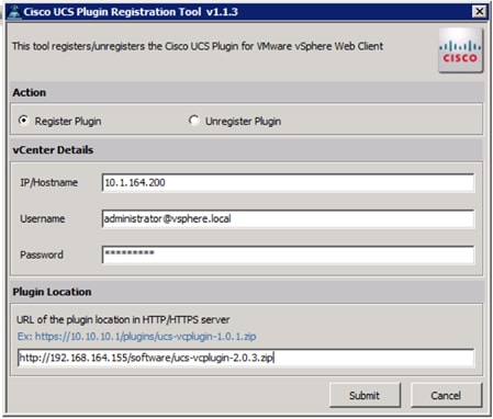
5. A pop-up will appear explaining that ‘allowHttp=true’ will need to be added to the webclient.properties file on the VCSA in the /etc/vmware/vsphere-client directory.
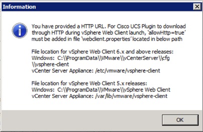
6. Take care of this issue after the plugin has been registered, click OK to close the Information dialogue box.
7. Click Submit to register the plugin with the vCenter Server Appliance.
8. To resolve the change needed for the HTTP download of the vSphere Web Client launch, connect to the VCSA with ssh using the root account and edit /etc/vmware/vsphere-client/webclient.properties to add “allowHttp=true” or type:
echo ’allowHttp=true’ >> /etc/vmware/vsphere-client/webclient.properties
![]() This will add “allowHttp=true” to the end of the webclient.properties file. Make sure to use two greater than symbols “>>” to append to the end of the configuration file, a single greater than symbol will replace the entire pre-existing file with what has been sent with the echo command.
This will add “allowHttp=true” to the end of the webclient.properties file. Make sure to use two greater than symbols “>>” to append to the end of the configuration file, a single greater than symbol will replace the entire pre-existing file with what has been sent with the echo command.
9. Reboot the VCSA.
FlashStack UCS Domain Registration
Registration of the FlashStack UCS Domain can now be performed. The account used will correlate to the permissions allowed to the plugin, admin will be used in our example, but a read only account could be used with the plugin if that was appropriate for the environment.
To register the UCS Domain, complete the following steps:
1. Opening up the vSphere Web Client.
2. Select the Home from the Navigator or drop-down options, and double-click the Cisco UCS icon appearing in the Administration section.
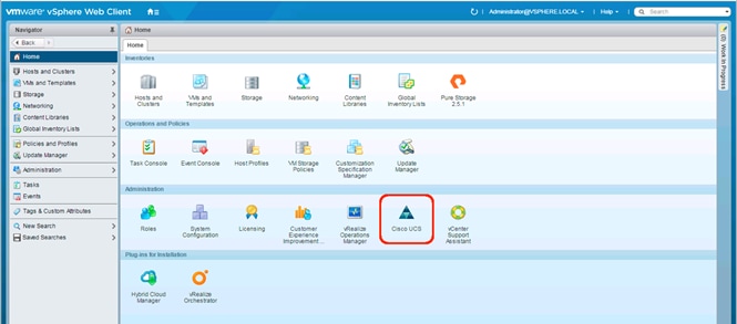
3. Click the Register button and provide the following options in the Register UCS Domain dialogue box that appears:
a. UCS Hostname/IP
b. Username
c. Password
d. Port (if different than 443)
e. Leave SSL selected and click the Visible to All users option
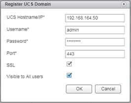
4. Click OK to register the UCS Domain.
Using the Cisco UCS vCenter Plugin
The plugin can now enable the functions described at the start of this section by double-clicking the registered UCS Domain:
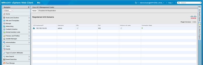
This will display a view of the components associated to the domain:
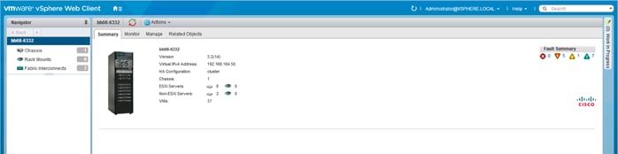
Selecting within the chassis or rack mounts will provide a list of ESXi or non-ESXi servers to perform operations on the following:
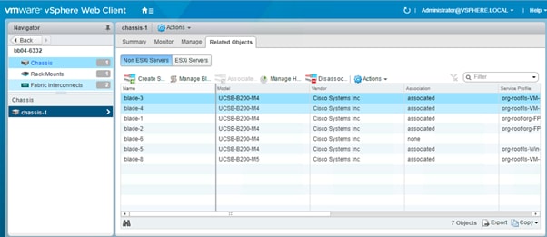
In addition to viewing and working within objects shown in the UCS Plug-in’s view of the UCS Domain, direct access of UCS functions provided by the plugin can be selected within the drop-down options of hosts registered to vCenter or within the Summary page of the ESXi host:
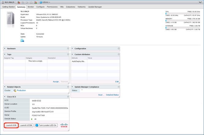
For full installation instructions and usage information, please refer to the Cisco UCS Manager Plug-in for VMware vSphere Web Client User Guide at: http://www.cisco.com/c/en/us/td/docs/unified_computing/ucs/sw/vmware_tools/vCenter/vCenter_Plugin_User_Guide/2x/b_vCenter_2x.html
Pure Storage Best Practices for vSphere
The Pure Storage FlashArray has very few necessary best practice changes for VMware ESXi. There are, though, a few requirements and considerations:
· Virtual Disk Types: Pure Storage recommends thin type virtual disks for the majority of virtual machines. Thin virtual disks are the most flexible and provide benefits such as in-guest space reclamation support. For virtual machines that demand the lowest possible latency with the most consistent performance, eagerzeroedthick virtual disks should be used. The use of zeroedthick (aka “lazy” or “sparse”) is discouraged at all times.
· Virtual Machine SCSI adapter: Pure Storage recommends using the Paravirtual SCSI adapter in virtual machines to provide access to virtual disks/RDMs. The Paravirtual SCSI adapter provides the highest possible performance levels with the most efficient use of CPU during intense workloads. Virtual machines with small I/O requirements can use the default adapters if preferred.
· Volume sizing and volume count: Pure Storage has no recommendations around volume sizing or volume count. The FlashArray volumes have no artificially limited queue depth, not on the volume level or the port level. A single volume can use the entire performance of the FlashArray if needed. In the case of very large volumes, or volumes serving intense workloads it might be necessary to increase internal queues inside of ESXi (HBA device queue, Disk.SchedNumReqOutstanding, virtual SCSI adapter queue).
· VMFS-6 is the recommended datastore type to enable automatic Run Space Reclamation (UNMAP) to ensure the FlashArray capacity usage accurately reflects the actual usage inside of VMware.
Configuration Example Files
Cisco Nexus 93180YC-EX A
version 7.0(3)I5(2)
switchname b19-93180-1
vdc b19-93180-1 id 1
limit-resource vlan minimum 16 maximum 4094
limit-resource vrf minimum 2 maximum 4096
limit-resource port-channel minimum 0 maximum 511
limit-resource u4route-mem minimum 248 maximum 248
limit-resource u6route-mem minimum 96 maximum 96
limit-resource m4route-mem minimum 58 maximum 58
limit-resource m6route-mem minimum 8 maximum 8
cfs eth distribute
feature interface-vlan
feature lacp
feature vpc
username admin password 5 $5$JXKeJeBt$AiT5ys/yITyKSslQRZJ0MX1AiaE160K89W5IwJ4r9q7 ro
le network-admin
ip domain-lookup
system default switchport
copp profile strict
snmp-server user admin network-admin auth md5 0x6a85fb275aedd28f4481cea9cd8724e1 priv
0x6a85fb275aedd28f4481cea9cd8724e1 localizedkey
rmon event 1 log trap public description FATAL(1) owner PMON@FATAL
rmon event 2 log trap public description CRITICAL(2) owner PMON@CRITICAL
rmon event 3 log trap public description ERROR(3) owner PMON@ERROR
rmon event 4 log trap public description WARNING(4) owner PMON@WARNING
rmon event 5 log trap public description INFORMATION(5) owner PMON@INFO
ntp server 192.168.164.254 use-vrf management
ntp source 10.1.164.13
ntp master 3
vlan 1-2,115,200-203
vlan 2
name Native-VLAN
vlan 115
name IB-MGMT-VLAN
vlan 200
name vMotion-VLAN
vlan 201
name VM-App1-VLAN
vlan 202
name VM-App2-VLAN
vlan 203
name VM-App3-VLAN
spanning-tree port type edge bpduguard default
spanning-tree port type edge bpdufilter default
spanning-tree port type network default
vrf context management
ip route 0.0.0.0/0 192.168.164.254
port-channel load-balance src-dst l4port
vpc domain 10
peer-switch
role priority 10
peer-keepalive destination 192.168.164.14 source 192.168.164.13
delay restore 150
peer-gateway
auto-recovery
ip arp synchronize
interface Vlan1
interface Vlan115
description In-Band NTP Redistribution Interface VLAN 115
no shutdown
no ip redirects
ip address 10.1.164.13/24
no ipv6 redirects
interface port-channel11
switchport mode trunk
switchport trunk native vlan 2
switchport trunk allowed vlan 115,200-203
spanning-tree port type network
vpc peer-link
interface port-channel151
switchport mode trunk
switchport trunk native vlan 2
switchport trunk allowed vlan 115,200-203
spanning-tree port type edge trunk
mtu 9216
load-interval counter 3 60
vpc 151
interface port-channel152
description UCS 6332-16UP-2 FI
switchport mode trunk
switchport trunk native vlan 2
switchport trunk allowed vlan 115,200-203
spanning-tree port type edge trunk
mtu 9216
load-interval counter 3 60
vpc 152
interface port-channel153
description Mgmt Switch
switchport mode trunk
switchport trunk native vlan 2
switchport trunk allowed vlan 115
spanning-tree port type network
mtu 9216
vpc 153
interface port-channel154
description Mgmt Switch
switchport mode trunk
switchport trunk native vlan 2
switchport trunk allowed vlan 115
spanning-tree port type network
mtu 9216
vpc 154
interface Ethernet1/1
description vPC peer-link connection to b19-93180-2 Ethernet1/1
switchport mode trunk
switchport trunk native vlan 2
switchport trunk allowed vlan 115,200-203
channel-group 11 mode active
no shutdown
interface Ethernet1/2
description vPC peer-link connection to b19-93180-2 Ethernet1/2
switchport mode trunk
switchport trunk native vlan 2
switchport trunk allowed vlan 115,200-203
channel-group 11 mode active
no shutdown
interface Ethernet1/3
interface Ethernet1/4
interface Ethernet1/5
interface Ethernet1/6
interface Ethernet1/7
interface Ethernet1/8
interface Ethernet1/9
interface Ethernet1/10
interface Ethernet1/11
interface Ethernet1/12
interface Ethernet1/13
interface Ethernet1/14
interface Ethernet1/15
interface Ethernet1/16
interface Ethernet1/17
interface Ethernet1/18
interface Ethernet1/19
interface Ethernet1/20
interface Ethernet1/21
interface Ethernet1/22
interface Ethernet1/23
interface Ethernet1/24
interface Ethernet1/25
interface Ethernet1/26
interface Ethernet1/27
interface Ethernet1/28
interface Ethernet1/29
interface Ethernet1/30
interface Ethernet1/31
interface Ethernet1/32
interface Ethernet1/33
interface Ethernet1/34
interface Ethernet1/35
interface Ethernet1/36
interface Ethernet1/37
interface Ethernet1/38
interface Ethernet1/39
interface Ethernet1/40
interface Ethernet1/41
interface Ethernet1/42
interface Ethernet1/43
interface Ethernet1/44
interface Ethernet1/45
interface Ethernet1/46
interface Ethernet1/47
interface Ethernet1/48
interface Ethernet1/49
interface Ethernet1/50
interface Ethernet1/51
description vPC 151 connection to UCS 6332-16UP-1 FI Ethernet1/33
switchport mode trunk
switchport trunk native vlan 2
switchport trunk allowed vlan 115,200-203
mtu 9216
load-interval counter 3 60
channel-group 151 mode active
no shutdown
interface Ethernet1/52
description vPC 152 connection to UCS 6332-16UP-2 FI Ethernet1/33
switchport mode trunk
switchport trunk native vlan 2
switchport trunk allowed vlan 115,200-203
mtu 9216
load-interval counter 3 60
channel-group 152 mode active
no shutdown
interface Ethernet1/53
description vPC 153 connection to Upstream Network Switch A
switchport mode trunk
switchport trunk native vlan 2
switchport trunk allowed vlan 115
mtu 9216
channel-group 153 mode active
no shutdown
interface Ethernet1/54
description vPC 154 connection to Upstream Network Switch B
switchport mode trunk
switchport trunk native vlan 2
switchport trunk allowed vlan 115
mtu 9216
channel-group 154 mode active
no shutdown
interface mgmt0
vrf member management
ip address 192.168.164.13/24
line console
line vty
boot nxos bootflash:/nxos.7.0.3.I5.2.bin
ip route 0.0.0.0/0 10.1.164.254
Cisco Nexus 93180YC-EX B
version 7.0(3)I5(2)
switchname b19-93180-2
vdc b19-93180-2 id 1
limit-resource vlan minimum 16 maximum 4094
limit-resource vrf minimum 2 maximum 4096
limit-resource port-channel minimum 0 maximum 511
limit-resource u4route-mem minimum 248 maximum 248
limit-resource u6route-mem minimum 96 maximum 96
limit-resource m4route-mem minimum 58 maximum 58
limit-resource m6route-mem minimum 8 maximum 8
cfs eth distribute
feature interface-vlan
feature lacp
feature vpc
username admin password 5 $5$D2EmPIzj$QAlwjzc/KcandBmhkr9rkukM88F6DPxCJi02Yj2TXV8 ro
le network-admin
ip domain-lookup
system default switchport
copp profile strict
snmp-server user admin network-admin auth md5 0xff46f80beea9e51b005db0cf74071b95 priv
0xff46f80beea9e51b005db0cf74071b95 localizedkey
rmon event 1 log trap public description FATAL(1) owner PMON@FATAL
rmon event 2 log trap public description CRITICAL(2) owner PMON@CRITICAL
rmon event 3 log trap public description ERROR(3) owner PMON@ERROR
rmon event 4 log trap public description WARNING(4) owner PMON@WARNING
rmon event 5 log trap public description INFORMATION(5) owner PMON@INFO
ntp server 192.168.164.254 use-vrf management
ntp source 10.1.164.14
ntp master 3
vlan 1-2,115,200-203
vlan 2
name Native-VLAN
vlan 115
name IB-MGMT-VLAN
vlan 200
name vMotion-VLAN
vlan 201
name VM-App1-VLAN
vlan 202
name VM-App2-VLAN
vlan 203
name VM-App3-VLAN
spanning-tree port type edge bpduguard default
spanning-tree port type edge bpdufilter default
spanning-tree port type network default
vrf context management
ip route 0.0.0.0/0 192.168.164.254
port-channel load-balance src-dst l4port
vpc domain 10
peer-switch
role priority 20
peer-keepalive destination 192.168.164.13 source 192.168.164.14
delay restore 150
peer-gateway
auto-recovery
ip arp synchronize
interface Vlan1
interface Vlan115
description In-Band NTP Redistribution Interface VLAN 115
no shutdown
no ip redirects
ip address 10.1.164.14/24
no ipv6 redirects
interface port-channel11
switchport mode trunk
switchport trunk native vlan 2
switchport trunk allowed vlan 115,200-203
spanning-tree port type network
vpc peer-link
interface port-channel151
switchport mode trunk
switchport trunk native vlan 2
switchport trunk allowed vlan 115,200-203
spanning-tree port type edge trunk
mtu 9216
load-interval counter 3 60
vpc 151
interface port-channel152
description UCS 6332-16UP-2 FI
switchport mode trunk
switchport trunk native vlan 2
switchport trunk allowed vlan 115,200-203
spanning-tree port type edge trunk
mtu 9216
load-interval counter 3 60
vpc 152
interface port-channel153
description Mgmt Switch
switchport mode trunk
switchport trunk native vlan 2
switchport trunk allowed vlan 115
spanning-tree port type network
mtu 9216
vpc 153
interface port-channel154
description Mgmt Switch
switchport mode trunk
switchport trunk native vlan 2
switchport trunk allowed vlan 115
spanning-tree port type network
mtu 9216
vpc 154
interface Ethernet1/1
description vPC peer-link connection to b19-93180-1 Ethernet1/1
switchport mode trunk
switchport trunk native vlan 2
switchport trunk allowed vlan 115,200-203
channel-group 11 mode active
no shutdown
interface Ethernet1/2
description vPC peer-link connection to b19-93180-1 Ethernet1/2
switchport mode trunk
switchport trunk native vlan 2
switchport trunk allowed vlan 115,200-203
channel-group 11 mode active
no shutdown
interface Ethernet1/3
interface Ethernet1/4
interface Ethernet1/5
interface Ethernet1/6
interface Ethernet1/7
interface Ethernet1/8
interface Ethernet1/9
interface Ethernet1/10
interface Ethernet1/11
interface Ethernet1/12
interface Ethernet1/13
interface Ethernet1/14
interface Ethernet1/15
interface Ethernet1/16
interface Ethernet1/17
interface Ethernet1/18
interface Ethernet1/19
interface Ethernet1/20
interface Ethernet1/21
interface Ethernet1/22
interface Ethernet1/23
interface Ethernet1/24
interface Ethernet1/25
interface Ethernet1/26
interface Ethernet1/27
interface Ethernet1/28
interface Ethernet1/29
interface Ethernet1/30
interface Ethernet1/31
interface Ethernet1/32
interface Ethernet1/33
interface Ethernet1/34
interface Ethernet1/35
interface Ethernet1/36
interface Ethernet1/37
interface Ethernet1/38
interface Ethernet1/39
interface Ethernet1/40
interface Ethernet1/41
interface Ethernet1/42
interface Ethernet1/43
interface Ethernet1/44
interface Ethernet1/45
interface Ethernet1/46
interface Ethernet1/47
interface Ethernet1/48
interface Ethernet1/49
interface Ethernet1/50
interface Ethernet1/51
description vPC 151 connection to UCS 6332-16UP-1 FI Ethernet1/34
switchport mode trunk
switchport trunk native vlan 2
switchport trunk allowed vlan 115,200-203
mtu 9216
load-interval counter 3 60
channel-group 151 mode active
no shutdown
interface Ethernet1/52
description vPC 152 connection to UCS 6332-16UP-2 FI Ethernet1/34
switchport mode trunk
switchport trunk native vlan 2
switchport trunk allowed vlan 115,200-203
mtu 9216
load-interval counter 3 60
channel-group 152 mode active
no shutdown
interface Ethernet1/53
description vPC 153 connection to Upstream Network Switch A
switchport mode trunk
switchport trunk native vlan 2
switchport trunk allowed vlan 115
mtu 9216
channel-group 153 mode active
no shutdown
interface Ethernet1/54
description vPC 154 connection to Upstream Network Switch B
switchport mode trunk
switchport trunk native vlan 2
switchport trunk allowed vlan 115
mtu 9216
channel-group 154 mode active
no shutdown
interface mgmt0
vrf member management
ip address 192.168.164.14/24
line console
line vty
boot nxos bootflash:/nxos.7.0.3.I5.2.bin
ip route 0.0.0.0/0 10.1.164.254
Cisco MDS 9148S A
version 6.2(21)
power redundancy-mode redundant
feature npiv
feature fport-channel-trunk
role name default-role
description This is a system defined role and applies to all users.
rule 5 permit show feature environment
rule 4 permit show feature hardware
rule 3 permit show feature module
rule 2 permit show feature snmp
rule 1 permit show feature system
username admin password 5 $5$VAPll/l.$7MBrRrPUWwxvuc5NSN19b2vv4N5yc09sFrofJ/6vgK3 role network-admin
ssh key rsa 2048
ip domain-lookup
ip host mds-9148s-a 192.168.164.15
aaa group server radius radius
snmp-server user admin network-admin auth md5 0x65ef5a4dec8cd0c72253a031d8595eba priv 0x65ef5a4dec8cd0c72253a031d85
95eba localizedkey
rmon event 1 log description FATAL(1) owner PMON@FATAL
rmon event 2 log description CRITICAL(2) owner PMON@CRITICAL
rmon event 3 log description ERROR(3) owner PMON@ERROR
rmon event 4 log description WARNING(4) owner PMON@WARNING
rmon event 5 log description INFORMATION(5) owner PMON@INFO
snmp-server community ucspm group network-operator
ntp server 192.168.164.254
ip access-list sl_def_acl permit tcp any any established
ip access-list sl_def_acl deny tcp any any eq port dst_telnet
ip access-list sl_def_acl deny tcp any any eq port dst_www
ip access-list sl_def_acl deny tcp any any eq port dst_ssh
ip access-list sl_def_acl permit ip any any
vsan database
vsan 101 name "Fabric-A"
device-alias database
device-alias name VM-Host-FC-01-A pwwn 20:00:00:25:b5:01:0a:08
device-alias name VM-Host-FC-02-A pwwn 20:00:00:25:b5:01:0a:09
device-alias name FlashStack-X-CT0FC0-fabricA pwwn 52:4a:93:76:87:ff:47:00
device-alias name FlashStack-X-CT0FC2-fabricA pwwn 52:4a:93:76:87:ff:47:02
device-alias name FlashStack-X-CT1FC0-fabricA pwwn 52:4a:93:76:87:ff:47:10
device-alias name FlashStack-X-CT1FC2-fabricA pwwn 52:4a:93:76:87:ff:47:12
device-alias commit
fcdomain fcid database
vsan 101 wwn 20:00:00:25:b5:01:0a:08 fcid 0xe0040b dynamic
! [VM-Host-FC-01-A]
vsan 101 wwn 20:00:00:25:b5:01:0a:09 fcid 0xe0040c dynamic
! [VM-Host-FC-02-A]
vsan 101 wwn 52:4a:93:76:87:ff:47:00 fcid 0xe00500 dynamic
! [FlashStack-X-CT0FC0-fabricA]
vsan 101 wwn 52:4a:93:76:87:ff:47:02 fcid 0xe00600 dynamic
! [FlashStack-X-CT0FC2-fabricA]
vsan 101 wwn 52:4a:93:76:87:ff:47:10 fcid 0xe00700 dynamic
! [FlashStack-X-CT1FC0-fabricA]
vsan 101 wwn 52:4a:93:76:87:ff:47:12 fcid 0xe00800 dynamic
! [FlashStack-X-CT1FC2-fabricA]
interface mgmt0
ip address 192.168.164.15 255.255.255.0
interface port-channel1
channel mode active
switchport rate-mode dedicated
vsan database
vsan 101 interface port-channel1
vsan 101 interface fc1/1
vsan 101 interface fc1/2
vsan 101 interface fc1/3
vsan 101 interface fc1/4
clock timezone EST -5 0
switchname mds-9148s-a
line console
line vty
boot kickstart bootflash:/m9100-s5ek9-kickstart-mz.6.2.21.bin
boot system bootflash:/m9100-s5ek9-mz.6.2.21.bin
interface fc1/5
interface fc1/6
interface fc1/7
interface fc1/8
interface fc1/1
interface fc1/2
interface fc1/3
interface fc1/4
interface fc1/9
interface fc1/10
interface fc1/11
interface fc1/12
interface fc1/13
interface fc1/14
interface fc1/15
interface fc1/16
interface fc1/17
interface fc1/18
interface fc1/19
interface fc1/20
interface fc1/21
interface fc1/22
interface fc1/23
interface fc1/24
interface fc1/25
interface fc1/26
interface fc1/27
interface fc1/28
interface fc1/29
interface fc1/30
interface fc1/31
interface fc1/32
interface fc1/33
interface fc1/34
interface fc1/35
interface fc1/36
interface fc1/37
interface fc1/38
interface fc1/39
interface fc1/40
interface fc1/41
interface fc1/42
interface fc1/43
interface fc1/44
interface fc1/45
interface fc1/46
interface fc1/47
interface fc1/48
interface fc1/5
interface fc1/6
interface fc1/7
interface fc1/8
zone smart-zoning enable vsan 101
!Active Zone Database Section for vsan 101
zone name VM-Host-FC-02-A vsan 101
member pwwn 20:00:00:25:b5:01:0a:09 init
! [VM-Host-FC-02-A]
member pwwn 52:4a:93:76:87:ff:47:00 target
! [FlashStack-X-CT0FC0-fabricA]
member pwwn 52:4a:93:76:87:ff:47:02 target
! [FlashStack-X-CT0FC2-fabricA]
member pwwn 52:4a:93:76:87:ff:47:10 target
! [FlashStack-X-CT1FC0-fabricA]
member pwwn 52:4a:93:76:87:ff:47:12 target
! [FlashStack-X-CT1FC2-fabricA]
zone name VM-Host-FC-01-A vsan 101
member pwwn 20:00:00:25:b5:01:0a:08 init
! [VM-Host-FC-01-A]
member pwwn 52:4a:93:76:87:ff:47:00 target
! [FlashStack-X-CT0FC0-fabricA]
member pwwn 52:4a:93:76:87:ff:47:02 target
! [FlashStack-X-CT0FC2-fabricA]
member pwwn 52:4a:93:76:87:ff:47:10 target
! [FlashStack-X-CT1FC0-fabricA]
member pwwn 52:4a:93:76:87:ff:47:12 target
! [FlashStack-X-CT1FC2-fabricA]
zoneset name flashstack-zoneset vsan 101
member VM-Host-FC-02-A
member VM-Host-FC-01-A
zoneset activate name flashstack-zoneset vsan 101
do clear zone database vsan 101
!Full Zone Database Section for vsan 101
zone name VM-Host-FC-02-A vsan 101
member pwwn 20:00:00:25:b5:01:0a:09 init
! [VM-Host-FC-02-A]
member pwwn 52:4a:93:76:87:ff:47:00 target
! [FlashStack-X-CT0FC0-fabricA]
member pwwn 52:4a:93:76:87:ff:47:02 target
! [FlashStack-X-CT0FC2-fabricA]
member pwwn 52:4a:93:76:87:ff:47:10 target
! [FlashStack-X-CT1FC0-fabricA]
member pwwn 52:4a:93:76:87:ff:47:12 target
! [FlashStack-X-CT1FC2-fabricA]
zone name VM-Host-FC-01-A vsan 101
member pwwn 20:00:00:25:b5:01:0a:08 init
! [VM-Host-FC-01-A]
member pwwn 52:4a:93:76:87:ff:47:00 target
! [FlashStack-X-CT0FC0-fabricA]
member pwwn 52:4a:93:76:87:ff:47:02 target
! [FlashStack-X-CT0FC2-fabricA]
member pwwn 52:4a:93:76:87:ff:47:10 target
! [FlashStack-X-CT1FC0-fabricA]
member pwwn 52:4a:93:76:87:ff:47:12 target
! [FlashStack-X-CT1FC2-fabricA]
zoneset name flashstack-zoneset vsan 101
member VM-Host-FC-02-A
member VM-Host-FC-01-A
interface fc1/1
switchport description flasharray-x-CT0FC0
port-license acquire
no shutdown
interface fc1/2
switchport description flasharray-x-CT0FC2
port-license acquire
no shutdown
interface fc1/3
switchport description flasharray-x-CT1FC0
port-license acquire
no shutdown
interface fc1/4
switchport description flasharray-x-CT1FC2
port-license acquire
no shutdown
interface fc1/5
switchport description UCS 6332-16UP Port 1
port-license acquire
channel-group 1 force
no shutdown
interface fc1/6
switchport description UCS 6332-16UP Port 2
port-license acquire
channel-group 1 force
no shutdown
interface fc1/7
switchport description UCS 6332-16UP Port 3
port-license acquire
channel-group 1 force
no shutdown
interface fc1/8
switchport description UCS 6332-16UP Port 4
port-license acquire
channel-group 1 force
no shutdown
interface fc1/9
interface fc1/10
interface fc1/11
interface fc1/12
interface fc1/13
interface fc1/14
interface fc1/15
interface fc1/16
interface fc1/17
interface fc1/18
interface fc1/19
interface fc1/20
interface fc1/21
interface fc1/22
interface fc1/23
interface fc1/24
interface fc1/25
interface fc1/26
interface fc1/27
interface fc1/28
interface fc1/29
interface fc1/30
interface fc1/31
interface fc1/32
interface fc1/33
interface fc1/34
interface fc1/35
interface fc1/36
interface fc1/37
interface fc1/38
interface fc1/39
interface fc1/40
interface fc1/41
interface fc1/42
interface fc1/43
interface fc1/44
interface fc1/45
interface fc1/46
interface fc1/47
interface fc1/48
ip default-gateway 192.168.164.254
Cisco MDS 9148S B
version 6.2(21)
power redundancy-mode redundant
feature npiv
feature fport-channel-trunk
role name default-role
description This is a system defined role and applies to all users.
rule 5 permit show feature environment
rule 4 permit show feature hardware
rule 3 permit show feature module
rule 2 permit show feature snmp
rule 1 permit show feature system
username admin password 5 $5$6BSGwPG5$SpgWoDQBQdZtf9UdnPo9fl93pRBjMBXgxIssnoJe.o9 role network-admin
ssh key rsa 2048
ip domain-lookup
ip host mds-9148s-b 192.168.164.16
aaa group server radius radius
snmp-server user admin network-admin auth md5 0x60988f2817fde405d4ec90d7cee74f1c priv 0x60988f2817fde405d4ec90d7cee74f
1c localizedkey
rmon event 1 log description FATAL(1) owner PMON@FATAL
rmon event 2 log description CRITICAL(2) owner PMON@CRITICAL
rmon event 3 log description ERROR(3) owner PMON@ERROR
rmon event 4 log description WARNING(4) owner PMON@WARNING
rmon event 5 log description INFORMATION(5) owner PMON@INFO
snmp-server community ucspm group network-operator
ntp server 192.168.164.254
vsan database
vsan 102 name "Fabric-B"
device-alias database
device-alias name VM-Host-FC-01-B pwwn 20:00:00:25:b5:01:0b:08
device-alias name VM-Host-FC-02-B pwwn 20:00:00:25:b5:01:0b:09
device-alias name FlashArray-X-CT0FC1-fabricB pwwn 52:4a:93:76:87:ff:47:01
device-alias name FlashArray-X-CT0FC3-fabricB pwwn 52:4a:93:76:87:ff:47:03
device-alias name FlashArray-X-CT1FC1-fabricB pwwn 52:4a:93:76:87:ff:47:11
device-alias name FlashArray-X-CT1FC3-fabricB pwwn 52:4a:93:76:87:ff:47:13
device-alias commit
fcdomain fcid database
vsan 102 wwn 20:00:00:25:b5:01:0b:08 fcid 0x640003 dynamic
! [VM-Host-FC-01-B]
vsan 102 wwn 20:00:00:25:b5:01:0b:09 fcid 0x640005 dynamic
! [VM-Host-FC-02-B]
vsan 102 wwn 52:4a:93:76:87:ff:47:13 fcid 0x640500 dynamic
! [FlashArray-X-CT1FC3-fabricB]
vsan 102 wwn 52:4a:93:76:87:ff:47:03 fcid 0x640600 dynamic
! [FlashArray-X-CT0FC3-fabricB]
vsan 102 wwn 52:4a:93:76:87:ff:47:11 fcid 0x640700 dynamic
! [FlashArray-X-CT1FC1-fabricB]
vsan 102 wwn 52:4a:93:76:87:ff:47:01 fcid 0x640800 dynamic
! [FlashArray-X-CT0FC1-fabricB]
interface mgmt0
ip address 192.168.164.16 255.255.255.0
interface port-channel2
channel mode active
switchport rate-mode dedicated
vsan database
vsan 102 interface port-channel2
vsan 102 interface fc1/1
vsan 102 interface fc1/2
vsan 102 interface fc1/3
vsan 102 interface fc1/4
clock timezone EST -5 0
switchname mds-9148s-b
line console
line vty
boot kickstart bootflash:/m9100-s5ek9-kickstart-mz.6.2.21.bin
boot system bootflash:/m9100-s5ek9-mz.6.2.21.bin
interface fc1/5
interface fc1/6
interface fc1/7
interface fc1/8
interface fc1/1
interface fc1/2
interface fc1/3
interface fc1/4
interface fc1/9
interface fc1/10
interface fc1/11
interface fc1/12
interface fc1/13
interface fc1/14
interface fc1/15
interface fc1/16
interface fc1/17
interface fc1/18
interface fc1/19
interface fc1/20
interface fc1/21
interface fc1/22
interface fc1/23
interface fc1/24
interface fc1/25
interface fc1/26
interface fc1/27
interface fc1/28
interface fc1/29
interface fc1/30
interface fc1/31
interface fc1/32
interface fc1/33
interface fc1/34
interface fc1/35
interface fc1/36
interface fc1/37
interface fc1/38
interface fc1/39
interface fc1/40
interface fc1/41
interface fc1/42
interface fc1/43
interface fc1/44
interface fc1/45
interface fc1/46
interface fc1/47
interface fc1/48
interface fc1/5
interface fc1/6
interface fc1/7
interface fc1/8
zone smart-zoning enable vsan 102
!Active Zone Database Section for vsan 102
!Active Zone Database Section for vsan 102
zone name VM-Host-FC-01-B vsan 102
member pwwn 20:00:00:25:b5:01:0b:08 init
! [VM-Host-FC-01-B]
member pwwn 52:4a:93:76:87:ff:47:01 target
! [FlashArray-X-CT0FC1-fabricB]
member pwwn 52:4a:93:76:87:ff:47:03 target
! [FlashArray-X-CT0FC3-fabricB]
member pwwn 52:4a:93:76:87:ff:47:13 target
! [FlashArray-X-CT1FC3-fabricB]
member pwwn 52:4a:93:76:87:ff:47:11 target
! [FlashArray-X-CT1FC1-fabricB]
zone name VM-Host-FC-02-B vsan 102
member pwwn 20:00:00:25:b5:01:0b:09 init
! [VM-Host-FC-02-B]
member pwwn 52:4a:93:76:87:ff:47:01 target
! [FlashArray-X-CT0FC1-fabricB]
member pwwn 52:4a:93:76:87:ff:47:03 target
! [FlashArray-X-CT0FC3-fabricB]
member pwwn 52:4a:93:76:87:ff:47:13 target
! [FlashArray-X-CT1FC3-fabricB]
member pwwn 52:4a:93:76:87:ff:47:11 target
! [FlashArray-X-CT1FC1-fabricB]
zoneset name flashstack-zoneset vsan 102
member VM-Host-FC-01-B
member VM-Host-FC-02-B
zoneset activate name flashstack-zoneset vsan 102
do clear zone database vsan 102
!Full Zone Database Section for vsan 102
zone name VM-Host-FC-01-B vsan 102
member pwwn 20:00:00:25:b5:01:0b:08 init
! [VM-Host-FC-01-B]
member pwwn 52:4a:93:76:87:ff:47:01 target
! [FlashArray-X-CT0FC1-fabricB]
member pwwn 52:4a:93:76:87:ff:47:03 target
! [FlashArray-X-CT0FC3-fabricB]
member pwwn 52:4a:93:76:87:ff:47:13 target
! [FlashArray-X-CT1FC3-fabricB]
member pwwn 52:4a:93:76:87:ff:47:11 target
! [FlashArray-X-CT1FC1-fabricB]
zone name VM-Host-FC-02-B vsan 102
member pwwn 20:00:00:25:b5:01:0b:09 init
! [VM-Host-FC-02-B]
member pwwn 52:4a:93:76:87:ff:47:01 target
! [FlashArray-X-CT0FC1-fabricB]
member pwwn 52:4a:93:76:87:ff:47:03 target
! [FlashArray-X-CT0FC3-fabricB]
member pwwn 52:4a:93:76:87:ff:47:13 target
! [FlashArray-X-CT1FC3-fabricB]
member pwwn 52:4a:93:76:87:ff:47:11 target
! [FlashArray-X-CT1FC1-fabricB]
interface fc1/1
switchport description flasharray-x-CT0FC1
port-license acquire
no shutdown
interface fc1/2
switchport description flasharray-x-CT0FC3
port-license acquire
no shutdown
interface fc1/3
switchport description flasharray-x-CT1FC1
port-license acquire
no shutdown
interface fc1/4
switchport description flasharray-x-CT1FC3
port-license acquire
no shutdown
interface fc1/5
switchport description UCS 6332-16UP Port 1
port-license acquire
channel-group 2 force
no shutdown
interface fc1/6
switchport description UCS 6332-16UP Port 2
port-license acquire
channel-group 2 force
no shutdown
interface fc1/7
switchport description UCS 6332-16UP Port 3
port-license acquire
channel-group 2 force
no shutdown
interface fc1/8
switchport description UCS 6332-16UP Port 4
port-license acquire
channel-group 2 force
no shutdown
interface fc1/9
interface fc1/10
interface fc1/11
interface fc1/12
interface fc1/13
interface fc1/14
interface fc1/15
interface fc1/16
interface fc1/17
interface fc1/18
interface fc1/19
interface fc1/20
interface fc1/21
interface fc1/22
interface fc1/23
interface fc1/24
interface fc1/25
interface fc1/26
interface fc1/27
interface fc1/28
interface fc1/29
interface fc1/30
interface fc1/31
interface fc1/32
interface fc1/33
interface fc1/34
interface fc1/35
interface fc1/36
interface fc1/37
interface fc1/38
interface fc1/39
interface fc1/40
interface fc1/41
interface fc1/42
interface fc1/43
interface fc1/44
interface fc1/45
interface fc1/46
interface fc1/47
interface fc1/48
ip default-gateway 192.168.164.254
Ramesh Isaac, Technical Marketing Engineer, Cisco Systems, Inc.
Ramesh Isaac is a Technical Marketing Engineer in the Cisco UCS Data Center Solutions Group. Ramesh has worked in data center and mixed-use lab settings since 1995. He started in information technology supporting UNIX environments and focused on designing and implementing multi-tenant virtualization solutions in Cisco labs before entering Technical Marketing. Ramesh holds certifications from Cisco, VMware, and Red Hat.
Cody Hosterman, Technical Director for Virtualization Ecosystem Integration at Pure Storage
Cody Hosterman focuses on the core VMware vSphere virtualization platform, VMware cloud and management applications and third-party products. He has a deep background in virtualization and storage technologies, including experience as a Solutions Engineer and Principal Virtualization Technologist. In his current position, he is responsible for VMware integration strategy, best practices, and developing new integrations and documentation. Cody has over 9 years of experience in virtualization and storage in various technical capacities. He is a VMware vExpert, and holds a bachelor’s degree from Pennsylvania State University in Information Sciences and Technology.
 Feedback