Cisco and Hitachi Adaptive Solutions with Cisco UCSX, VMware 8U1, and Hitachi VSP 5600 Design Guide
Available Languages
Bias-Free Language
The documentation set for this product strives to use bias-free language. For the purposes of this documentation set, bias-free is defined as language that does not imply discrimination based on age, disability, gender, racial identity, ethnic identity, sexual orientation, socioeconomic status, and intersectionality. Exceptions may be present in the documentation due to language that is hardcoded in the user interfaces of the product software, language used based on RFP documentation, or language that is used by a referenced third-party product. Learn more about how Cisco is using Inclusive Language.
- US/Canada 800-553-2447
- Worldwide Support Phone Numbers
- All Tools
 Feedback
 Feedback
Published: December 2023
In partnership with:
![]()
About the Cisco Validated Design Program
The Cisco Validated Design (CVD) program consists of systems and solutions designed, tested, and documented to facilitate faster, more reliable, and more predictable customer deployments. For more information, go to: http://www.cisco.com/go/designzone.
Cisco and Hitachi are introducing this Adaptive Solutions for Converged Infrastructure Virtual Server Infrastructure (VSI) as a validated reference architecture, documented as a Cisco Validated Design (CVD). This converged infrastructure design is powered by industry-leading Hitachi storage and Cisco compute, and is your assurance for a robust, high-performance, and scalable data center. Trusted by global customers with their critical applications and data, the hybrid cloud platform is a natural choice to accelerate application performance, boost efficiency, and deliver unparalleled data availability, while meeting sustainability goals.
The release of this CVD includes this design guide as well as additional deployment guides covering standard and automated deployment approaches. This architecture brings together decades of industry expertise and superior technologies to meet the enterprise business challenges of today and position our customers for the future.
This Adaptive Solutions CVD release incorporates the 7th generation of Cisco Unified Computing System (Cisco UCS) servers, including Cisco UCS C-Series and Cisco UCS X-Series Servers, powered using 4th Gen Intel Xeon Scalable processors. The new Cisco UCS X-Series M7 servers delivers an energy-efficient infrastructure, consuming 31 percent less power than the previous blade chassis, with advanced monitoring and management to help Enterprises meet their sustainability goals. Cisco UCS X-Series also received the 2023 SEAL Sustainable Product Award, which recognizes products "purpose-built" for a sustainable future.
Cisco delivers the LAN and SAN through the Cisco Nexus 9000 Series switches along with Cisco MDS Fibre Channel switches to enable Cisco UCS X-Series with the Hitachi Virtual Storage Platform (VSP). The Hitachi VSP 5600 is a storage system that is part of the Hitachi Virtual Storage Platform (VSP) 5000 Series.
Some of the key advantages within this design are:
• Storage for performance and availability-critical workloads: The VSP 5600 model offers a 42 percent improvement in data reduction efficiency, increasing more usable capacity. With end-to-end NVMe, the new VSP 5600 model delivers up to 33 million IOPS and as low as 39 microseconds of latency.
• New generation of servers: the 7th generation of Cisco UCS servers is improved with the 4th Gen Intel Xeon Scalable Processors with up to 60 cores per processor and up 8TB of DDR-4800 DIMMs.
• End-to-End 32Gbps Fibre Channel: utilizing the 5th Generation Cisco UCS Virtual Interface Card (VIC) 15231, the 5th Generation Cisco UCS 6536 Fabric Interconnect, and the Cisco UCS X9108-100G Intelligent Fabric Module to deliver 32Gbps of Fibre Channel (SCSI and NVMe) connectivity from the VSP 5600 storage system to the Cisco UCS servers.
• Innovative cloud operations: continuous feature delivery with Cisco Intersight removing the need for maintaining on-premises virtual machines supporting management functions.
• Built for investment protections: design enabled for future technologies such as 64G Fibre Channel, 400G Ethernet, liquid cooling, and high-Wattage CPUs; CXL (Compute Express Link) ready hardware.
This architecture is brought together with VMware vSphere 8.0 U1 as the hypervisor for the Adaptive Solutions VSI. VMware vSphere continues to be the commanding preference amongst enterprise virtualization customers, and this release includes new features increasing operational efficiency, as well as increased metrics to determine energy efficiency.
The growing library of Adaptive Solutions content can be found here: https://www.cisco.com/c/en/us/solutions/design-zone/data-center-design-guides/data-center-design-guides-all.html#Hitachi
This chapter contains the following:
• Audience
Cisco and Hitachi are in partnership to create this Adaptive Solutions for Converged Infrastructure Cisco Validated Design (CVD) to bring further value to our joint customers in creating the modern data center. This data center is built with the Adaptive Solutions for Converged Infrastructure (CI) design, for Virtual Server Infrastructure (VSI) incorporating components and best practices from both companies to deliver the power, scalability, and resiliency to address the business needs of our customers. Leveraging decades of industry expertise and superior technology, this Cisco CVD offers a resilient, agile, and flexible foundation for today’s businesses. In addition, the Cisco and Hitachi partnership extends beyond a single solution, enabling businesses to benefit from their ambitious roadmap of evolving technologies such as advanced analytics, IoT, cloud, and edge capabilities. With Cisco and Hitachi, organizations can confidently take the next step in their modernization journey and prepare themselves to take advantage of new business opportunities enabled by innovative technology.
This document describes a validated approach for deploying Cisco and Hitachi technologies as private cloud infrastructure. The recommended solution architecture consists of Cisco Unified Computing System X-Series (Cisco UCS X-Series), Cisco Nexus 9000 Series switches, Cisco MDS Fibre channel switches, and Hitachi Virtual Storage Platform (VSP). It is based on VMware vSphere 8.0 U1 to meet the most relevant needs of customer deployments and delivers multiple new features for optimizing storage utilization and facilitating private cloud common to these releases.
The intended audience of this document includes but is not limited to IT architects, sales engineers, field consultants, professional services, IT managers, partner engineering, and customers who want to take advantage of an infrastructure built to deliver IT efficiency and enable IT innovation.
This document provides design guidance around incorporating the Cisco Intersight managed Cisco UCS X-Series platform and the Hitachi VSP 5600 in the Adaptive Solutions architecture. This document introduces various design elements and explains various considerations and best practices for a successful deployment. It also highlights the design and product requirements for integrating virtualization and storage systems to Cisco Intersight to deliver a true cloud-based integrated approach to infrastructure management.
Adaptive Solutions for Converged Infrastructure is a powerful and scalable architecture, leveraging the strengths of both Cisco and Hitachi, delivered in a unified support model. The Adaptive Solutions Virtual Server Infrastructure data center is brought together as a validated architecture using the following components:
• Cisco Unified Computing System featuring Cisco UCS X-Series servers
• Cisco Nexus family of switches
• Cisco MDS multilayer fabric switches
• Hitachi Virtual Storage Platform featuring the VSP 5600
The Adaptive Solutions architecture presents 100Gbps compute along with a 32Gbps Fibre Channel storage network implemented for VMware vSphere 8.0 U1. The Cisco UCS X-Series compute is implemented and overseen within the cloud by Cisco Intersight, giving an additional operational view of all layers of the infrastructure through the Cisco SaaS platform of Intersight. The Hitachi VSP storage is additionally configured and given greater operational oversight through Hitachi Ops Center.
The following design elements are new to the Adaptive Solutions architecture:
• Cisco UCS X210c M7 servers with Intel Xeon Scalable Processors with up to 60 cores per processor and up to 8TB of DDR-4800 DIMMs
• 100Gbps Ethernet and 32Gbps Fibre Channel in Adaptive Solutions
• Integration of the 5th Generation Cisco UCS 6536 Fabric Interconnect into Adaptive Solutions
• Integration of the 5th Generation Cisco UCS 15000-Series VICs into Adaptive Solutions
• Integration of the Cisco UCS X9108-100G Intelligent Fabric Module into the Cisco UCS X-Series 9508 Chassis
• Deployment of Cisco UCS with Cisco Intersight Managed Mode (IMM)
• VMware vSphere 8.0 Update 1
• Hitachi Virtual Storage Platform (VSP) 5600
• Hitachi Ops Center release version 10.9.3.
• Hitachi Storage Provider for VMware vCenter release version 3.7.3.
This chapter contains the following:
• Cisco Unified Compute System X-Series
• Cisco UCS C220 M7 and C240 M7 Rack Servers
• Cisco UCS 6536 Fabric Interconnects
• Cisco Nexus Switching Fabric
• Cisco MDS 9124V 64G Multilayer Fabric Switch
• Cisco Nexus Dashboard Fabric Controller
• Hitachi Virtual Storage Platform
• Hitachi Unified Compute Platform Advisor
• Hitachi Storage Plug-in for VMware vCenter
• Hitachi Storage Provider for VMware vCenter
• Hitachi Remote Ops (Hi-Track)
The Adaptive Solutions Virtual Server Infrastructure (VSI) is a reference architecture comprised of components and best practices from Cisco and Hitachi.
Figure 1. Adaptive Solutions Components
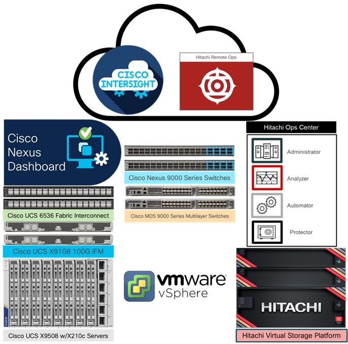 The Cisco and Hitachi components used in Adaptive Solutions designs have been validated within this reference architecture so customers have a relevant example they can use to explicitly deploy in their environment or adjust as needed within the respective product compatibility lists of Cisco and Hitachi. The best practices are intended to be relevant across supported product families, but deployment steps may differ when using supported components other than those shown in this design. Each of the component families shown in Figure 1 (Cisco UCS, Cisco Nexus, Cisco MDS, and Hitachi VSP) offers platform and resource options to scale up or scale out the infrastructure while supporting the same features.
The Adaptive Solutions hardware is built with the following components:
• Cisco UCS X9508 Chassis with Cisco UCS X9108-100G Intelligent Fabric Modules and up to eight Cisco UCS X210c M7 Compute Nodes.
• Fifth-generation Cisco UCS 6536 Fabric Interconnects to support 10/25/40/100GbE and 16/32GbFC connectivity from various components.
• High-speed Cisco NX-OS-based Nexus 93600CD-GX switching design to supporting 100GE connectivity with up to 400GE uplink connections.
• Future proof Cisco MDS 9124V switches to support up to 64G Fibre Channel connectivity.
• Hitachi Virtual Storage Platform 5000 series (VSP 5000 series) represents the industry’s highest performing and most scalable storage solution. Built on 57 years of Hitachi engineering experience and innovation in the IT sector, VSP 5000 series offers superior performance, resiliency, and agility, featuring response times as low as 39 microseconds, and all backed up with the industry’s first and most comprehensive 100 percent data availability guarantee.
The software components of the solution consist of:
• Cisco Intersight platform to deploy the Cisco UCS components and maintain and support the infrastructure.
• Cisco Intersight Assist Virtual Appliance to help connect Hitachi VSP, Cisco Nexus switches, Cisco MDS Switches, and VMware vCenter to Cisco Intersight, giving visibility and management capabilities to these elements.
• Cisco Nexus Dashboard with Cisco Nexus Dashboard Fabric Controller for complete lifecycle management of Cisco NX-OS based SAN fabrics.
• VMware vSphere 8.0 U1 to incorporate new features to the release, including the Cisco Intersight enabled Hardware Support Manager (HSM) of Cisco UCS firmware.
• Hitachi Ops Center Administrator to provide a unified management platform for Hitachi storage systems that manages and monitors their storage infrastructure from a single console, simplifying management tasks and improving operational efficiency.
• Hitachi Ops Center API Configuration Manager REST enables programmatic management of Hitachi storage systems. It is an independent and lightweight component that includes CCI (Command Control Interface), which is used as part of the configuration manager REST API. It uses LAN or Fibre Channel network-based communication with the targeted storage system.
• Hitachi Unified Compute Platform (UCP) Advisor provides features that automate and simplify deployment and management of multiple Hitachi VSP systems within a native VMware vSphere web client environment. The Hitachi Unified Compute Platform Advisor allows you to perform storage-based operations on Hitachi enterprise storage allowing VMware administrators to manage and deploy their storage from a native VMware environment.
• Hitachi Storage Provider for VMware vCenter (VASA Provider) is a virtual appliance that enables organizations to deploy software-defined storage solutions for VMware vSphere Virtual Volumes (vVols) on Hitachi Virtual Storage Platform (VSP) systems and provide storage policy-based provisioning for both VMFS and vVols datastores.
• Hitachi Remote Ops monitors, alerts, collects data and provides analytics to customers about Hitachi solutions continuously.
• VMware vCenter to set up and manage the virtual infrastructure as well as Cisco Intersight integration.
Cisco Unified Computing System X-Series
The Cisco UCS X-Series Modular System is designed to take the current generation of the Cisco UCS platform to the next level with its future-ready design and cloud-based management. Decoupling and moving the platform management to the cloud allows Cisco UCS to respond to customer feature and scalability requirements in a much faster and efficient manner. Cisco UCS X-Series state of the art hardware simplifies the data-center design by providing flexible server options. A single server type, supporting a broader range of workloads, results in fewer different data-center products to manage and maintain. The Cisco Intersight cloud-management platform manages Cisco UCS X-Series as well as integrating with third-party devices, including VMware vCenter and Hitachi storage, to provide visibility, optimization, and orchestration from a single platform, thereby driving agility and deployment consistency.
Figure 2. Cisco UCS X9508 Chassis
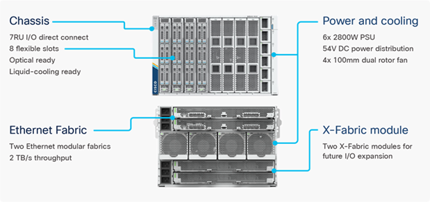
Cisco UCS X9508 Chassis
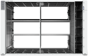
The Cisco UCS X-Series chassis is engineered to be adaptable and flexible. As seen in Figure 3, the Cisco UCS X9508 chassis has only a power-distribution midplane. This midplane-free design provides fewer obstructions for better airflow. For I/O connectivity, vertically oriented compute nodes intersect with horizontally oriented fabric modules, allowing the chassis to support future fabric innovations. Cisco UCS X9508 Chassis’ superior packaging enables larger compute nodes, thereby providing more space for actual compute components, such as memory, GPU, drives, and accelerators. Improved airflow through the chassis enables support for higher power components, and more space allows for future thermal solutions (such as liquid cooling) without limitations.
Figure 3. Cisco UCS X9508 Chassis – Midplane Free Design
The Cisco UCS X9508 7-Rack-Unit (7RU) chassis has eight flexible slots. These slots can house a combination of compute nodes and a pool of current and future I/O resources that includes GPU accelerators, disk storage, and nonvolatile memory. At the top rear of the chassis are two Intelligent Fabric Modules (IFMs) that connect the chassis to upstream Cisco UCS 6400 or 6500 Series Fabric Interconnects. At the bottom rear of the chassis are slots to house X-Fabric modules that can flexibly connect the compute nodes with I/O devices. Six 2800W Power Supply Units (PSUs) provide 54V power to the chassis with N, N+1, and N+N redundancy. A higher voltage allows efficient power delivery with less copper and reduced power loss. Efficient, 100mm, dual counter-rotating fans deliver industry-leading airflow and power efficiency, and optimized thermal algorithms enable different cooling modes to best support the customer’s environment.
Cisco UCS 9108-100G Intelligent Fabric Modules
In the end-to-end 100Gbps Ethernet design, for the Cisco UCS X9508 Chassis, the network connectivity is provided by a pair of Cisco UCS 9108-100G Intelligent Fabric Modules (IFMs). Like the fabric extenders used in the Cisco UCS 5108 Blade Server Chassis, these modules carry all network traffic to a pair of Cisco UCS 6536 Fabric Interconnects (FIs). IFMs also host the Chassis Management Controller (CMC) for chassis management. In contrast to systems with fixed networking components, Cisco UCS X9508’s midplane-free design enables easy upgrades to new networking technologies as they emerge making it straightforward to accommodate new network speeds or technologies in the future.
Figure 4. Cisco UCS 9108-100G Intelligent Fabric Module
Each IFM supports eight 100Gb uplink ports for connecting the Cisco UCS X9508 Chassis to the FIs and 8 100Gb server ports for the eight compute nodes. IFM server ports can provide up to 200 Gbps of unified fabric connectivity per compute node across the two IFMs. The uplink ports connect the chassis to the Cisco UCS FIs, providing up to 1600Gbps connectivity across the two IFMs. The unified fabric carries management, VM, and Fibre Channel over Ethernet (FCoE) traffic to the FIs, where management traffic is routed to the Cisco Intersight cloud operations platform, FCoE traffic is forwarded to either native Fibre Channel interfaces through unified ports on the FI (to Cisco MDS switches) or to FCoE uplinks (to Cisco Nexus switches supporting SAN switching), and data Ethernet traffic is forwarded upstream to the data center network (via Cisco Nexus switches).
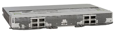
Cisco UCS X210c M7 Compute Node
The Cisco UCS X9508 Chassis is designed to host up to 8 Cisco UCS X210c M7 Compute Nodes. The hardware details of the Cisco UCS X210c M7 Compute Nodes are shown in Figure 5.
Figure 5. Figure 5 Cisco UCS X210c M7 Compute Node
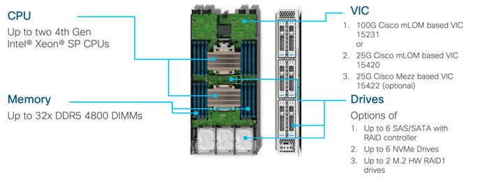
The Cisco UCS X210c M7 features:
• CPU: Up to 2x 4th Gen Intel Xeon Scalable Processors with up to 60 cores per processor and 2.6 MB Level 3 cache per core.
• Memory: Up to 32 x 256 GB DDR5-4800 DIMMs for a maximum of 8 TB of main memory.
• Disk storage: Up to 6 SAS or SATA drives can be configured with an internal RAID controller, or customers can configure up to 6 NVMe drives. 2 M.2 memory cards can be added to the Compute Node with optional RAID 1 mirroring.
• Virtual Interface Card (VIC): Up to 2 VICs including an mLOM Cisco UCS VIC 15231 (100Gbps) or an mLOM Cisco UCS VIC 15420 (50Gbps) and a mezzanine Cisco UCS VIC card 15422 can be installed in a Compute Node to pair with and extend the connectivity of the Cisco UCS VIC 15420 adapter.
• Security: The server supports an optional Trusted Platform Module (TPM). Additional security features include a secure boot FPGA and ACT2 anti-counterfeit provisions.
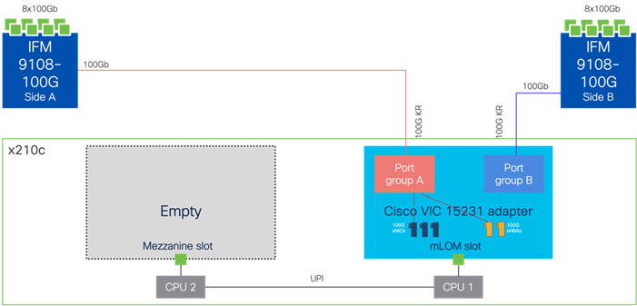
Cisco UCS VIC 15231
Cisco UCS VIC 15231 fits the mLOM slot in the Cisco UCS X210c Compute Node and enables up to 100 Gbps of unified fabric connectivity to each of the chassis IFMs for a total of 200 Gbps of connectivity per server. Cisco UCS VIC 15231 connectivity to the IFM and up to the fabric interconnects is delivered through 100Gbps. Cisco UCS VIC 15231 supports 512 virtual interfaces (both FCoE and Ethernet) capable of providing 100Gbps, along with the latest networking innovations including NVMeoF over FC or TCP, and VxLAN/NVGRE offload.
Figure 6. Cisco UCS VIC 15231 in Cisco UCS X210c M7
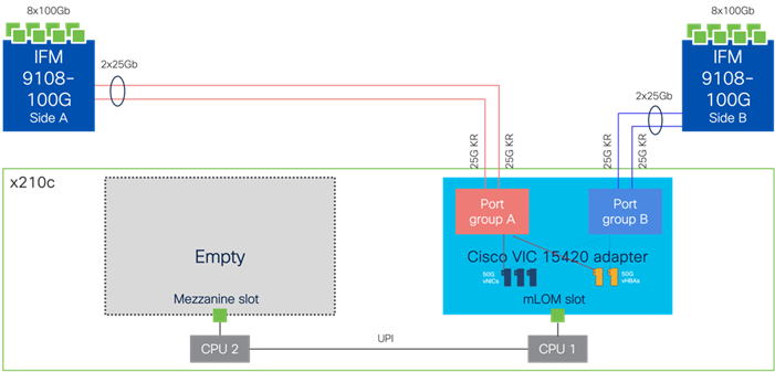
Cisco UCS VIC 15420
Cisco UCS VIC 15420 fits the mLOM slot in the Cisco UCS X210c Compute Node and enables up to 50 Gbps of unified fabric connectivity to each of the chassis IFMs for a total of 100 Gbps of connectivity per server. Cisco UCS VIC 15420 connectivity to the IFM and up to the fabric interconnects is delivered through 4x 25-Gbps connections, which are configured automatically as 2x 50-Gbps port channels. Cisco UCS VIC 15420 supports 512 virtual interfaces (both Fibre Channel and Ethernet) capable of providing 50Gbps, along with the latest networking innovations including NVMeoF over RDMA (ROCEv2), and VxLAN/NVGRE offload.
Figure 7. Cisco UCA VIC 15420 in Cisco UCS X210c M7
Cisco UCS VIC 15420 and VIC 15422
The optional Cisco UCS VIC 15422 fits the mezzanine slot on the server to extend the bandwidth of a Cisco UCS VIC 15420 equipped compute node. The connections between the previous 4th generation Cisco UCS VIC 1440 plus Port Expander in the Cisco UCS B200 blades and the I/O modules in the Cisco UCS 5108 chassis are comprised of multiple 10Gbps KR lanes extending between mLOM and Mezzanine slots to increase bandwidth. The same connections between Cisco UCS VIC 15420 and IFMs in Cisco UCS X-Series comprise of multiple 25Gbps KR links resulting in higher speed connectivity in Cisco UCS X210c M7 Compute Nodes when connecting to either the 9108-100G or the 9108-25G IFMs.
Figure 8. Cisco UCS VIC 15420 and 115422 in Cisco UCS X210c M7
A bridge card (UCSX-V5-BRIDGE) extends this VIC’s 2x 50 Gbps of network connections up to the mLOM slot and out through the mLOM’s IFM connectors, bringing the total bandwidth to 100 Gbps per fabric for a total bandwidth of 200 Gbps per server. This pairing presents an effective capacity of 200Gbps for the vNICs and vHBAs but will need to be distributed between at least four 50Gbps virtual interfaces to realize this capacity.
Cisco UCS C220 M7 and C240 M7 Rack Servers
The Cisco UCS C220 M7 (1RU) and C240 M7 (2RU) Rack Servers extend the capabilities of the Cisco UCS rack server portfolio with the addition of up to two 4th Gen Intel Xeon Scalable CPUs, with up to 52 cores per socket within the Cisco UCS C220 M7 and up to 60 cores per socket in the Cisco UCS C240 M7.
Figure 9. Cisco UCS C220 M7 Rack Server
The Cisco UCS C220 M7 has a maximum memory capacity for 2 CPUs of 4 TB (for 32 x 128 GB DDR5 4800 MT/s DIMMs), with the Cisco UCS C240 M7 having a larger memory capacity of 8 TB (for 32 x 256 GB DDR5 4800 MT/s DIMMs) for 2 CPUs. The Cisco UCS C220 M7 supports up to 3 PCIe 4.0 slots or up to 2 PCIe 5.0 slots, while the Cisco UCS C240 M7 provides increased capacity allowing for up to 8 PCIe 4.0 slots or up to 4 PCIe 5.0 slots, with both providing a modular LAN on motherboard (mLOM) slot.
Figure 10. Cisco UCS C240 M7 Rack Server
The Cisco UCS C220 M7 supports up to 3 GPUs, and the Cisco UCS C240 M7 servers expands this to support up to 5 GPUs per server. Both servers support several PCIe and mLOM VIC options for connecting to the Cisco UCS 6536 Fabric Interconnects, allowing for quad port 10/25/50 Gbps or dual port 40/100/200 Gbps network connectivity. The Cisco UCS C220 M7 and C240 M7 servers are valid within an Adaptive Solutions architecture but are not featured within this design.
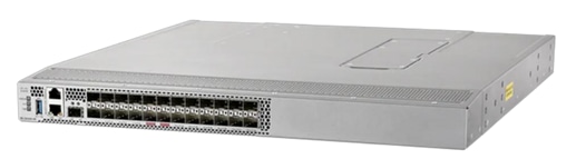
Cisco UCS 6536 Fabric Interconnects
The Cisco UCS Fabric Interconnects (FIs) provide a single point for connectivity and management for the entire Cisco UCS system. Typically deployed as an active/active pair, the system’s FIs integrate all components into a single, highly available management domain controlled by Cisco Intersight (currently, the Cisco UCS 6536 FI does not support Cisco UCS Manager). Cisco UCS FIs provide a single unified fabric for the system, with low-latency, lossless, cut-through switching that supports LAN, SAN, and management traffic using a single set of cables.
Figure 11. Cisco UCS 6536 Fabric Interconnect
The Cisco UCS 6536 FI utilized in the current design is a 36-port Fabric Interconnect. This single RU device includes up to 36 10/25/40/100 Gbps Ethernet ports, 16 8/16/32-Gbps Fibre Channel ports via 4 128 Gbps to 4x32 Gbps breakouts on ports 33-36. All 36 ports support breakout cables or QSA interfaces.
Note: The Cisco UCS 6536 FI was initially released to only support Intersight Managed Mode (IMM). This has changed and Cisco UCS Manager (UCSM) mode is now supported on the Cisco UCS 6536 Fabric Interconnects to include Cisco UCS X-Series, Cisco UCS B-Series Blade Servers, Cisco UCS C-Series Rack Servers, Cisco UCS S-Series Storage Servers, as well as the associated storage resources and networks.
The Cisco Intersight platform is a Software-as-a-Service (SaaS) infrastructure lifecycle management platform that delivers simplified configuration, deployment, maintenance, and support. The Cisco Intersight platform is designed to be modular, so you can adopt services based on their individual requirements. The platform significantly simplifies IT operations by bridging applications with infrastructure, providing visibility and management from bare-metal servers and hypervisors to serverless applications, thereby reducing costs and mitigating risk. This unified SaaS platform uses a unified Open API design that natively integrates with third-party platforms and tools.
Figure 12. Cisco Intersight Overview
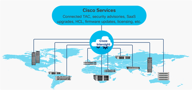
The main benefits of Cisco Intersight infrastructure services are as follows:
• Stay ahead of problems with global visibility and accelerate trouble resolution through proactive support capabilities.
• Provide role based access control (RBAC) to resources within the data center through a single platform.
• Intersight Cloud Orchestrator (ICO) provides a task based “low code” workflow approach to executing storage operations.
• Combine the convenience of a SaaS platform with the capability to connect from anywhere and manage infrastructure through a browser or mobile app.
• Elimination of silos for managing datacenter ecosystem as all components, including Hitachi storage can be managed via Intersight.
• Upgrade to add workload optimization and Kubernetes services when needed.
Cisco Intersight Virtual Appliance and Private Virtual Appliance
In addition to the SaaS deployment model running on Intersight.com, on-premises options can be purchased separately. The Cisco Intersight Virtual Appliance and Cisco Intersight Private Virtual Appliance are available for organizations that have additional data locality or security requirements for managing systems. The Cisco Intersight Virtual Appliance delivers the management features of the Cisco Intersight platform in an easy-to-deploy VMware Open Virtualization Appliance (OVA) or Microsoft Hyper-V Server virtual machine that allows you to control the system details that leave your premises. The Cisco Intersight Private Virtual Appliance is provided in a form factor specifically designed for those who operate in disconnected (air gap) environments. The Private Virtual Appliance requires no connection to public networks or back to Cisco to operate.
Cisco Intersight Assist
Cisco Intersight Assist helps you add endpoint devices to Cisco Intersight. A data center could have multiple devices that do not connect directly with Cisco Intersight. Any device that is supported by Cisco Intersight, but does not connect directly with it, will need a connection mechanism. Cisco Intersight Assist provides that connection mechanism to include Cisco Nexus switches, Cisco MDS switches, the Cisco Nexus Dashboard, and the Hitachi Virtual Storage Platform.
Cisco Intersight Assist is available within the Cisco Intersight Virtual Appliance, which is distributed as a deployable virtual machine contained within an Open Virtual Appliance (OVA) file format. More details about the Cisco Intersight Assist VM deployment configuration are described in later sections.
Licensing Requirements
The Cisco Intersight platform uses a subscription-based license with multiple tiers. You can purchase a subscription duration of one, three, or five years and choose the required Cisco UCS server volume tier for the selected subscription duration. You can purchase any of the following higher-tier Cisco Intersight licenses using the Cisco ordering tool:
• Cisco Intersight Essentials: Essentials offers comprehensive monitoring and inventory visibility across global locations, UCS Central Software and Cisco Integrated Management Controller (IMC) supervisor entitlement, policy-based configuration with server profiles, firmware management, Connected TAC with Proactive RMAs, and evaluation of compatibility with the Cisco Hardware Compatibility List (HCL).
• Cisco Intersight Advantage: Advantage offers all the features and functions of the Essentials tier. It includes storage widgets and cross-domain inventory correlation across compute, storage, and virtual environments (VMware ESXi). It also includes OS installation for supported Cisco UCS platforms and Intersight Orchestrator for orchestration across Cisco UCS and third party systems.
Servers in the Cisco Intersight Managed Mode require at least the Essentials license. For more information about the features provided in the various licensing tiers, see https://intersight.com/help/getting_started#licensing_requirements.
Cisco Hardware Support Manager
The Cisco Hardware Support Manager (HSM) service option enabled with vSphere Lifecycle Manager (vLCM) plug-in allows you to update the Operating System and perform firmware upgrades simultaneously with a single firmware image. The HSM is integrated with Cisco Intersight Infrastructure Service, which enables you to manage your vCenter server instance.
The Cisco Nexus 9000 Series Switches offer both modular and fixed 1/10/25/40/100/400 Gigabit Ethernet switch configurations with scalability up to 115 Tbps of nonblocking performance with less than five-microsecond latency, wire speed VXLAN gateway, bridging, and routing support.
Figure 13. Cisco Nexus 93600CD-GX Switch
The Cisco Nexus 9000 series switch featured in this design is the Cisco Nexus 93600CD-GX configured in NX-OS standalone mode. NX-OS is a purpose-built data-center operating system designed for performance, resiliency, scalability, manageability, and programmability at its foundation. It provides a robust and comprehensive feature set that meets the demanding requirements of virtualization and automation.
The Cisco Nexus 93600CD-GX Switch is a 1RU switch that supports 12 Tbps of bandwidth and 4.0 bpps across 28 fixed 40/100G QSFP-28 ports and 8 fixed 10/25/40/50/100/200/400G QSFP-DD ports. Breakout supported on ports, 25-36: 2x200, 4x100, 2x100, 8x50, 4x50, 2x50, 4x25, 4x10, and 10G w/QSA. This switch was chosen for this solution because of its robust uplink capabilities in a 1RU format, and future-proofness of 400G capacity.
Port groups within the 93600CD-GX switches follow specific requirements when configuring breakout ports, which is explained in the hardware installation guide, here: https://www.cisco.com/c/en/us/td/docs/switches/datacenter/nexus9000/hw/n93600cd-gx-hig/guide/b_c93600cd-gx-nxos-mode-hardware-installation-guide/m_overview1.html
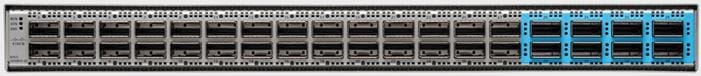
Cisco MDS 9124V 64G Multilayer Fabric Switch
The next-generation Cisco MDS 9124V 64-Gbps 24-Port Fibre Channel Switch (Figure 14) supports 64, 32, and 16 Gbps Fibre Channel ports and provides high-speed Fibre Channel connectivity for all-flash arrays and high-performance hosts. This switch offers state-of-the-art analytics and telemetry capabilities built into its next-generation Application-Specific Integrated Circuit (ASIC) chipset. This switch allows seamless transition to Fibre Channel Non-Volatile Memory Express (NVMe/FC) workloads whenever available without any hardware upgrade in the SAN. It empowers small, midsize, and large enterprises that are rapidly deploying cloud-scale applications using extremely dense virtualized servers, providing the benefits of greater bandwidth, scale, and consolidation.
Figure 14. Cisco MDS 9124V 64G Multilayer Fabric Switch
The Cisco MDS 9124V delivers advanced storage networking features and functions with ease of management and compatibility with the entire Cisco MDS 9000 family portfolio for reliable end-to-end connectivity. This switch also offers state-of-the-art SAN analytics and telemetry capabilities that have been built into this next-generation hardware platform. This new state-of-the-art technology couples the next-generation Cisco port ASIC with a fully dedicated network processing unit designed to complete analytics calculations in real time. The telemetry data extracted from the inspection of the frame headers are calculated on board (within the switch) and, using an industry-leading open format, can be streamed to any analytics-visualization platform. This switch also includes a dedicated 10/100/1000BASE-T telemetry port to maximize data delivery to any telemetry receiver including the Cisco Nexus Dashboard Fabric Controller. The Cisco MDS 9148V 48-Port Fibre Channel Switch is also available when more ports are needed.
Cisco Nexus Dashboard Fabric Controller
Cisco Nexus Dashboard Fabric Controller (NDFC) is the next generation of Cisco’s Data Center Network Manager (DCNM). It is a comprehensive management and automation solution for all Cisco Nexus and Cisco Multilayer Distributed Switching (MDS) platforms powered by Cisco NX-OS. NDFC provides management, automation, control, monitoring, and integration for deployments spanning LAN, SAN, and IP Fabric for Media (IPFM) fabrics. NDFC facilitates seamless interconnectivity, automation, and management for hybrid-cloud environments.
NDFC provides a rich set of features which include:
• Management through fabric-oriented configuration and operations visibility, providing oversight of large deployments with little overhead. This is presented through the Nexus Dashboard, but also a RESTful API for easy integration.
• Automation within a simple deployment approach to bootstrapping new fabrics in both private and hybrid cloud environments. Fabric builder policy templates and automatic bootstrapping create greatly simplified deployments.
• Monitoring and visualization are achieved with active topology views per fabric. Combined with Cisco’s Nexus Dashboard Insights, customers receive a comprehensive view enabling in depth visibility to their day-2 operations.
• SAN management within Adaptive Solutions using NDFC provides a number of additional operational features including backups, image management, and Device Manager access for switches added to the fabric.
Hitachi Virtual Storage Platform
Hitachi Virtual Storage Platform is a highly scalable, true enterprise-class storage system that can virtualize external storage and provide virtual partitioning and quality of service for diverse workload consolidation. With the industry’s only 100 percent data availability guarantee, Virtual Storage Platform delivers the highest uptime and flexibility for your block-level storage needs.
Figure 15. Hitachi Virtual Storage Platform
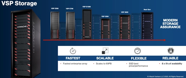
Hitachi Virtual Storage Platform 5000 Series
The VSP 5200 and VSP 5600 models provide enhanced capacity efficiency with improved data reduction performance along with SCM tiering and full end-to-end NVMe. Hitachi Virtual Storage Platform 5000 series storage systems reliably deliver more data faster than ever for open-systems and mainframe applications. These enterprise-level storage systems are available in configurations with up to 69 PB of raw capacity and with scalability to manage up to 33 million IOPS with latency as low as 39 µs accelerates application response and increases application consolidation, making these models the most powerful and most responsive storage systems available. The Hitachi Remote Ops monitoring system and Hitachi Ops Center Analyzer software enable superior uptime. To ensure that operations are always up and running, VSP 5000 series models can optionally be backed by a 100 percent data availability guarantee.
Hardware-assisted data reduction technology offers up to a 40 percent performance improvement over existing VSP 5000 series models. Nondisruptive data-in-place (DIP) migration is provided when upgrading from VSP 5100 to VSP 5600 or from VSP 5500 to VSP 5600.
VSP 5000 series provides high performance, high availability, and reliability for enterprise-class data centers and features the industry's most comprehensive suite of local and remote data protection capabilities, including true active-active metro-clustering. When combined with server virtualization, storage virtualization supports applications at cloud scale while reducing complexity.
VSP 5000 series is the first storage in the industry to offer a mixed NVMe, SCM solid-state disk (SSD), serial-attached SCSI (SAS) SSD, and HDD environment that can not only scale up in capacity but also scale out for performance. VSP 5000 series models include the industry leading VSP 5100 and VSP 5500 models and the newest VSP 5200 and VSP 5600 models.
Figure 16. Hitachi Virtual Storage Platform 5600
Hitachi VSP 5000 Key Features
• Agility and scalability
VSP 5100 and VSP 5200 all-flash arrays (AFAs) are scale-up enterprise storage platforms with one pair of controller nodes supporting open and mainframe workloads. VSP 5500 and VSP 5600 AFAs start with a single node pair and can scale out to three node pairs. All of these models are also available as hybrid arrays (VSP 5100H, VSP 5200H, VSP 5500H, VSP 5600H) that support the following drive types:
◦ NVMe SCM
◦ NVMe SSD
◦ SAS SSD
◦ SAS FMD (available only when upgrading to VSP 5600)
◦ SAS HDD
Note: The VSP 5100 and VSP 5200 models support either SAS or NVMe configurations, while VSP 5500 and VSP 5600 support mixed SAS and NVMe backend configurations.
• All-flash performance accelerated by NVMe technology
NVMe drives provide high throughput and low latency to achieve high response performance, enabling large volumes of data to be processed rapidly with response times as low as 39 microseconds. NVMe storage class memory (SCM) drives provide significantly quicker access to data, up to 10 times faster than flash drives, and are more durable than flash drives.
• Capacity efficiency
The advanced adaptive data reduction (ADR) technologies of the VSP 5000 series provide a guaranteed effective capacity of 4:1 to improve storage utilization and reduce storage footprint. Compression and also deduplication, if desired, can be enabled for all internal and external storage media at the volume level for enhanced tunability.
• Reliability and resiliency
Leveraging hot-swappable components, nondisruptive maintenance and upgrades, and outstanding data protection, VSP 5000 series offers complete system redundancy and is backed by a 100 percent data availability guarantee. The active-active controller architecture of VSP 5000 series protects against local faults and performance issues, and hardware redundancy eliminates all active single points of failure, no matter how unlikely, to provide the highest level of reliability and data availability.
• Artificial-intelligence-based solutions
All VSP 5000 series models come with Hitachi Ops Center Analyzer, which analyzes telemetry to optimize application performance and prevent extended outages. Manual administrative tasks are streamlined and implemented with fewer errors, facilitating the addition of new applications and the expansion of existing applications. In addition, Hitachi Ops Center Analyzer works with Hitachi Ops Center Automator to maintain best practices and quality of service (QoS).
• Simple, easy-to-use management
VSP 5000 series can be set up quickly and managed with ease using Hitachi Ops Center Administrator. Ops Center Administrator reduces the complexity of steps needed to deploy, monitor, and reconfigure storage resources. Additionally, REST APIs allow integration with existing toolsets and automation templates to further consolidate management tasks.
Hitachi Ops Center Suite delivers enhanced AIOps capabilities using AI/ML to provide real-time monitoring and to increase performance and tuning of your storage environment. For more information about Hitachi Virtual Storage Platform 5000 Series, see: https://www.hitachivantara.com/en-us/products/storage-platforms/primary-block-storage/vsp-5000-series.html
Hitachi Virtual Storage Platform E1090 Series
The Hitachi Virtual Storage Platform E series builds on 58 years of proven Hitachi engineering experience, offering you a superior range of business continuity options that provide the best reliability in the industry. As a result, 85 percent of Fortune 100 financial services companies trust Hitachi storage systems with their mission-critical data.
The Hitachi Virtual Storage Platform E1090 (VSP E1090) storage system is a high-performance, large-capacity data storage system. The VSP E1090 all-flash arrays (AFAs) support NVMe and SAS solid-state drives (SSDs). The VSP E1090H hybrid models can be configured with both SSDs and hard disk drives (HDDs).
The NVMe flash architecture delivers consistent, low-microsecond latency, which reduces the transaction costs of latency-critical applications and delivers predictable performance to optimize storage resources.
The hybrid architecture allows for greater scalability and provides data-in-place migration support.
The storage systems offer superior performance, resiliency, and agility, featuring response times as low as 41μ, all backed up with the industry’s first and most comprehensive 100% data availability guarantee.
The Hitachi Virtual Storage Platform E series innovative active-active controller architecture protects your business against local faults while mitigating performance issues as well as providing all enterprise features of the VSP 5000 series in a lower cost form factor to satisfy midrange customer needs and business requirements.
Hitachi VSP E1090 Key features
• High performance
◦ Multiple controller configuration distributes processing across controllers
◦ High-speed processing facilitated by up to 1,024 GiB of cache
◦ I/O processing speed increased by NVMe flash drives
◦ High-speed front-end data transfer up to 32 Gbps for FC and 10 Gbps for iSCSI
◦ I/O response times as low as low as 41 μ
◦ Integrated with Hitachi Ops Center to improve IT operational efficiencies
• High reliability
◦ Service continuity for all main components due to redundant configuration
◦ RAID 1, RAID 5, and RAID 6 support (RAID 6 including 14D+2P)
◦ Data security by transferring data to cache flash memory in case of a power outage
• Scalability and versatility
◦ Scalable capacity up to 25.9 PB, 287 PB (external), and 8.4M IOPS
◦ The hybrid architecture allows for greater scalability and provides data-in-place migration support
• Performance and Resiliency Enhancements
◦ Upgraded controllers with 14 percent more processing power than VSP E990 and 53 percent more processing power than VSP F900
◦ Significantly improved adaptive data reduction (ADR) performance through Compression Accelerator Modules
◦ An 80 percent reduction in drive rebuild time compared to earlier midsized enterprise platforms
◦ Smaller access size for ADR metadata reduces overhead
◦ Support for NVMe allows extremely low latency with up to 5 times higher cache miss IOPS per drive
• Reliability and serviceability
The Virtual Storage Platform (VSP) E1090 storage system is designed to deliver industry-leading performance and availability. The VSP E1090 features a single, flash-optimized Storage Virtualization Operating System (SVOS) image running on 64 processor cores, sharing a global cache of 1 TiB. The VSP E1090 offers higher performance with fewer hardware resources than competitors. The VSP E1090 was upgraded to an advanced Cascade Lake CPU, permitting read response times as low as 41 microseconds and data reduction throughput was improved up to 2X by the new Compression Accelerator Module. Improvements in reliability and serviceability allow the VSP E1090 to claim an industry-leading 99.9999% availability (on average, 0.3 seconds per year of downtime expected).
• Advanced AIOps and easy-to-use management
The Hitachi Virtual Storage Platform E series achieves greater efficiency and agility with Hitachi Ops Center’s advanced AIOps which provide real-time monitoring for VSP E series systems located on-premises or in a colocation facility. Hitachi’s advanced AIOps provides unique integration of IT analytics and automation that identifies issues and, through automation, quickly resolves issues before they impact your critical workloads. Ops Center uses the latest AI and machine learning (ML) capabilities to improve IT operations through an Ops Center simplifies day-to-day administrative, optimization and management orchestration for VSP E-Series, freeing you to focus on innovation and strategic initiatives.
Figure 17. Hitachi Virtual Storage Platform E1090
For more information about Hitachi Virtual Storage Platform E-Series, see: https://www.hitachivantara.com/en-us/products/storage-platforms/primary-block-storage/vsp-e-series.html
Hitachi Virtual Storage Platform Software Components and Features
Hitachi Storage Virtualization Operating System RF
Hitachi Storage Virtualization Operating System (SVOS) RF (Resilient Flash) delivers best-in-class business continuity and data availability and simplifies storage management of all Hitachi VSPs by sharing a common operating system. Flash performance is optimized with a patented flash-aware I/O stack to further accelerate data access. Adaptive inline data reduction increases storage efficiency while enabling a balance of data efficiency and application performance. Industry-leading storage virtualization allows Hitachi Storage Virtualization Operating System RF to use third-party all-flash and hybrid arrays as storage capacity, consolidating resources and extending the life of storage investments.
Hitachi Storage Virtualization Operating System RF works with the virtualization capabilities of the Hitachi VSP storage systems to provide the foundation for global storage virtualization. SVOS RF delivers software-defined storage by abstracting and managing heterogeneous storage to provide a unified virtual storage layer, resource pooling, and automation. Hitachi Storage Virtualization Operating System RF also offers self-optimization, automation, centralized management, and increased operational efficiency for improved performance and storage utilization. Optimized for flash storage, Hitachi Storage Virtualization Operating System RF provides adaptive inline data reduction to keep response times low as data levels grow, and selectable services enable data-reduction technologies to be activated based on workload benefit.
Hitachi Storage Virtualization Operating System RF integrates with Hitachi’s base and advanced software packages to deliver superior availability and operational efficiency. You gain active-active clustering, data-at-rest encryption, insights via machine learning, and policy-defined data protection with local and remote replication.
Figure 18. Hitachi Storage Virtualization Operating System RF Features
For more information about Hitachi Storage Virtualization Operating System RF, see: https://www.hitachivantara.com/en-us/products/storage-platforms/primary-block-storage/virtualization-operating-system.html
Hitachi Thin Image Provisioning Advanced
Hitachi Thin Image Advanced (HTI Advanced) enables you to perform cost-effective replication by storing only the differential data between the primary volumes (P-VOLs) and secondary volumes (S-VOLs). Thin Image Advanced stores snapshots in a Hitachi Virtual Storage Platform family (VSP family) storage system. If a logical data failure occurs in the storage system due to erroneous data update or virus infection, you can restore it using the stored snapshot of the data. Pairs created by using Thin Image Advanced are called Thin Image Advanced pairs.
The high-speed, nondisruptive snapshot technology of Hitachi Thin Image Advanced snapshot software rapidly creates up to one million point-in-time copies of mission-critical information within any Hitachi storage system or virtualized storage pool, without impacting host service or performance levels. Because snapshots store only the changed data, the volume of storage capacity required for each snapshot copy volume is greatly reduced. As a result, Hitachi Thin Image Advanced can provide significant savings over full-volume cloning methods. These snapshot copies are fully read/write compatible with other hosts and can be used for system backups, application testing and data mining applications while the business continues to run at full capacity.
• Thin Image Advanced snapshots rapidly create up to 1,024 instant point-in-time copies for data protection or application testing.
• Saves up to 90 percent or more disk space by storing only changed data blocks.
• Speeds backups from hours to a few minutes, virtually eliminating traditional backup windows.
• Near-instant restoration of critical data to increase business continuity.
• Application- and OS-independent but can be integrated with application backup triggers.
• Fast, simple, and reliable snapshot software.
Figure 19. Hitachi Thin Image Provisioning Advanced
For more information on Hitachi Thin Image Advanced, see: https://knowledge.hitachivantara.com/Documents/Management_Software/SVOS/9.8.7/Local_Replication/Thin_Image_Advanced/01_Overview_of_Thin_Image_Advanced
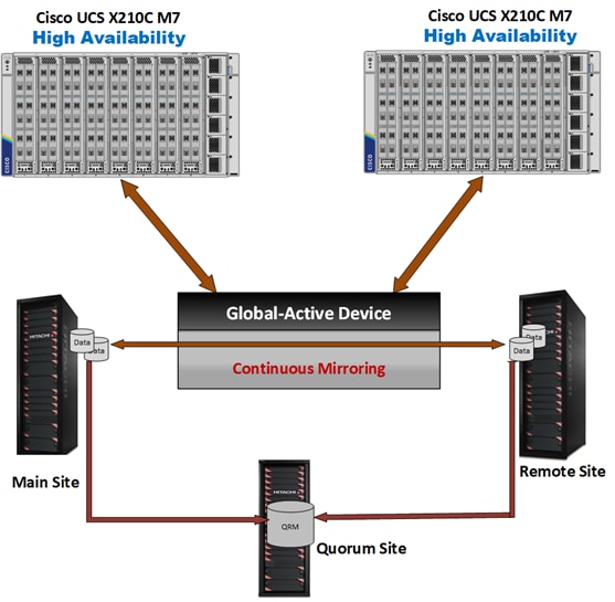
High Availability with Global-active Device
Global-active device enables you to create and maintain synchronous, remote copies of data volumes. A Virtual Storage Machine (VSM) is configured in the primary and secondary storage systems using the actual information of the primary storage system, and the global-active device primary and secondary volumes are assigned the same virtual LDEV (Logical Device) number in the VSM. This enables the host to see the pair volumes as a single volume on a single storage system, and both volumes receive the same data from the host. A quorum disk, which can be in a third and external storage system or in an iSCSI-attached host server, is used to monitor the global-active device pair volumes. The quorum disk acts as a heartbeat for the global-active device pair, with both storage systems accessing the quorum disk to check on each other. A communication failure between systems results in a series of checks with the quorum disk to identify the problem so the system can receive host updates.
Global-active device simplifies and automates high availability to ensure continuous operations for mission-critical data and applications. Global-active device provides full metro clustering between data centers that can be up to 500 km apart. Supporting read/write copies of the same data in two places at the same time, global-active device 's active-active design implements cross-mirrored storage volumes between matched VSP storage systems to protect data and minimize data-access disruptions for host applications due to site or storage system failures. Global-active device ensures that up-to-date data is always available and enables production workloads on both systems, while maintaining full data consistency and protection.
Figure 20. Global Active Device between Primary and Secondary Data Centers
VMware Native Multi-Pathing (NMP) on the host runs in the Active/Active configuration. While this configuration works well at campus distances, at metro distances Asymmetric Logical Unit Access (ALUA) is required to support optimized/nonoptimized paths and ensure that the shortest path is used. If the host cannot access the primary volume (P-VOL) or secondary volume (S-VOL), host I/O is redirected by the alternate path software to the appropriate volume without any impact to the host applications.
Global-active device volume pairs have the following benefits:
• Continuous I/O: If a primary volume becomes unavailable, the host continues to transparently access the secondary volume.
• Clustered failover: You do not need to perform storage system tasks such as suspension or resynchronization of global-active device pairs due to a host failure.
• Host Load Balancing: If a virtual machine or host is creating a high load at one site, you can move the load to the other site.
• High performance: Multipath software allows application access to mirrored data from the shortest path for highest performance.
• Workload mobility: The concurrent data mirroring capability of global-active device makes data immediately available to servers at a second site (over metro distances).
• Nondisruptive data migration: Data volumes can be migrated between storage systems without disruption to normal operations.
For more information about High availability with global-active device with Cisco UCS, see: https://www.cisco.com/c/en/us/td/docs/unified_computing/ucs/UCS_CVDs/cisco_hitachi_adaptivesolutions_ci_stretcheddc.html
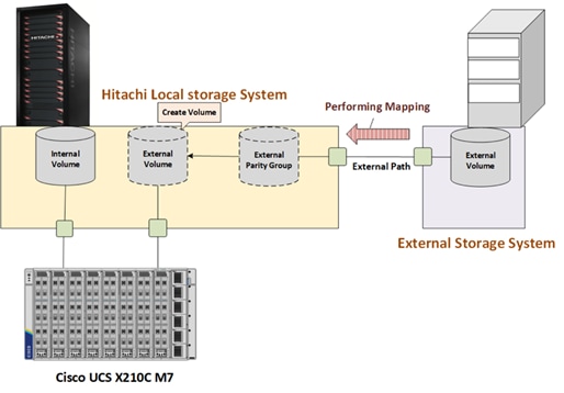
Hitachi Universal Volume Manager
Hitachi Universal Volume Manager (UVM) is a built-in capability that allows virtualization of legacy or third-party storage devices behind the Hitachi VSP, thus allowing all storage to be managed from a single system along with providing all native VSP capabilities to the virtualized system. To use volumes on the external system on the target VSP, external path connections must be made between the controllers of the external storage system and the target VSP. Once physical connections are made, volumes of the external storage system must be mapped to the target VSP. External volumes can be used in situations such as:
• Backup of target VSP storage volumes to an external storage system.
• Using the capacity of external storage system through the target VSP.
• Migration of data from legacy external storage system to the new target VSP.
Figure 21 shows the system components and configuration for UVM.
Figure 21. Hitachi Universal Volume Manager Operations for VSP storage system
For more information about Hitachi UVM, see: https://www.hitachivantara.com/en-us/pdf/architecture-guide/vsp-universal-volume-manager-with-cisco-intersight.pdf
Hitachi Ops Center is an integrated suite of applications that enable you to optimize your data center operations through integrated configuration, analytics, automation, and copy data management. These features allow you to administer, automate, optimize, and protect your Hitachi storage infrastructure.
The following modules are included in the Hitachi Ops Center:
• Ops Center Administrator
• Ops Center Analyzer
• Ops Center Automator
• Ops Center Protector
• Ops Center API Configuration Manager
• Ops Center Analyzer Viewpoint
Figure 22. Hitachi Ops Center Products

Hitachi Ops Center Administrator
Hitachi Ops Center Administrator is an infrastructure management solution that unifies storage provisioning, data protection, and storage management across the entire Hitachi Virtual Storage Platform family.
Figure 23. Hitachi Ops Center Administrator UI Console
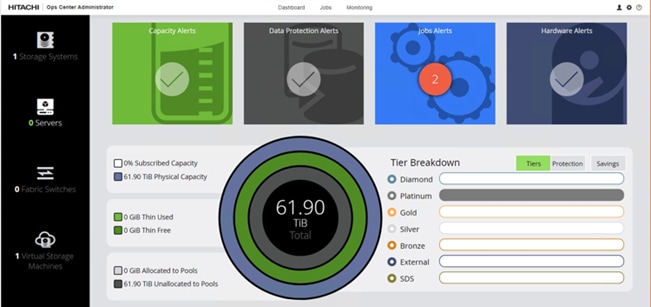
The Hitachi Ops Center Administrator key benefits are:
• Reduction in administration time and effort to efficiently deploy and manage new storage resources via Administrators easy to use interface.
• Utilization of common configurations to centrally manage multiple Hitachi Virtual Storage Platform systems.
• Standard based APIs which enable fast storage provisioning operations and integration with external tools.
• Utilize common administrative workflows to manage highly available storage volumes.
• Integrate with Hitachi Ops Center management to incorporate analytics, automation, and data protection.
For more information on Hitachi Ops Center Administrator, see: https://www.hitachivantara.com/en-us/products/storage-software/ai-operations-management/ops-center/administrator.html
Ops Center Analyzer
Ops Center Analyzer provides a comprehensive application service-level and storage performance management solution that enables you to quickly identify and isolate performance problems, determine the root cause, and provide solutions. It enables proactive monitoring from the application level through server, network, and storage resources for end-to-end visibility of your monitored environment. It also increases performance and storage availability by identifying problems before they can affect applications.
Figure 24. Hitachi Ops Center Analyzer UI Console
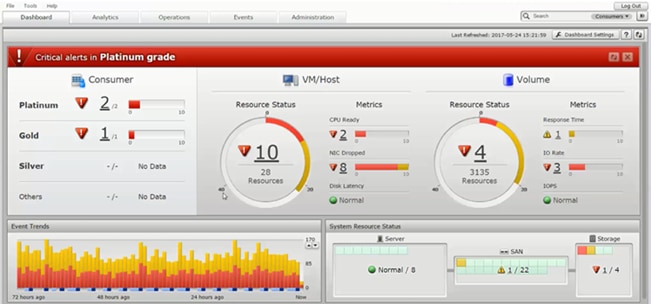
The Ops Center Analyzer collects and correlates data from these sources:
• Storage systems
• Fibre Channel switches
• Hypervisors
• Hosts
For more information on Hitachi Ops Center Analyzer, see: https://www.hitachivantara.com/en-us/products/storage-software/ai-operations-management/ops-center/analyzer.html
Ops Center Analyzer Viewpoint
Ops Center Analyzer viewpoint displays user the operational status of data centers around the world in a single window allowing comprehensive insight to global operations.
Figure 25. Hitachi Ops Center Analyzer viewpoint
With Hitachi Ops Center Analyzer Viewpoint, the following information can be utilized:
• Check the overall status of multiple data centers: By accessing Analyzer viewpoint from a web browser, you can collectively display and view information about supported resources in the data centers. Even for a large-scale system consisting of multiple data centers, you can check the comprehensive status of all data centers.
• Easily analyze problems related to resources: By using the UI, you can display information about resources in a specific data center in a drill-down view and easily identify where a problem occurred. Additionally, since you can launch the Ops Center Analyzer UI from the Analyzer viewpoint UI, you can quickly perform the tasks needed to resolve the problem.
For more Information about Ops Center, see: https://www.hitachivantara.com/en-us/products/storage-software/ai-operations-management/ops-center.html
Hitachi Ops Center Protector
With Hitachi Ops Center Protectors you can easily configure in-system or remote-replication with the Hitachi VSP. Protector as a enterprise data copy management platform provides business-defined data protection, which simplifies the creation and management of complex, business-defined policies to meet service-level objectives for availability, recoverability, and retention.
Figure 26. Hitachi Ops Center Protector UI Console
For more information about Hitachi Ops Center Protector, see: https://www.hitachivantara.com/en-us/products/storage-software/data-protection-cyber-resiliency/ops-center-protector.html
Hitachi Ops Center Automator
Hitachi Ops Center Automator is a software solution that provides automation to simplify end-to-end data management tasks such as storage provisioning for storage and data center administrators. The building blocks of the product are prepackaged automation templates known as service templates which can be customized and configured for other people in the organization to utilize as a self-service model hence reducing the load on traditional administrative staff.
Figure 27. Hitachi Ops Center Automator UI Console
For more information on Hitachi Ops Center Automator, see: https://www.hitachivantara.com/en-us/products/storage-software/ai-operations-management/ops-center/automator.html
Hitachi Ops Center API Configuration Manager
Hitachi Ops Center API Configuration Manager REST is an independent and light weight binary which enables programmatic management of Hitachi VSP storage systems using restful APIs. This component can be deployed stand alone or as a part of Hitachi Ops Center.
The REST API supports the following storage systems:
• VSP 5000 series
• VSP E Series
• VSP F Series VSP G Series
Figure 28. Hitachi Ops Center API Configuration Manager
Hitachi Unified Compute Platform Advisor
Hitachi Unified Compute Platform (UCP) Advisor simplifies IT management and orchestration for faster and easier deployment of storage resources which back the Cisco UCS ecosystem. Hitachi UCP Advisor has features that allow VMware administrators to manage native Hitachi storage in their vSphere environments and provides the capability to manage multiple VSP storage systems with a single instance of UCP Advisor.
With Hitachi Unified Compute Platform Advisor, VMware administrators get greater insight into Hitachi VSP storage system capacity metrics, along with an insight into the following native to the RAID subsystem.
The following information can be viewed with the help of Hitachi Unified Computer Platform Advisor:
• Datastore
• Parity groups
• Logical units
• Storage pools
• Ports
• Host groups
• Replication pairs
• Resource groups
Hitachi UCP Advisor allows various storage management operations to be performed from the native VMware vCenter Web Client user interface. The storage provisioning operations include the following:
• Datastore Provisioning: This creates a backend logical unit (LU), mounts the LU to host groups, and mounts VMFS datastores to your virtual environment. This can be done in a single operation using UCP Advisor.
• Parity Group Provisioning: This gives insight to available parity group resources within a RAID system. It enables the creation of a parity group based on drive type and RAID level directly from the Unified Compute Platform Advisor plug-in.
• Logical Unit Provisioning: Administrators can view all created logical units on the RAID subsystem, even though they may have been provisioned by another storage management product. With Unified Compute Platform Advisor, you can provision a new LU directly from the pools available on the storage system.
• Storage Pool Provisioning: With UCP Advisor, administrators have the ability to carve various storage pools which include pools created with Hitachi Dynamic Provisioning, Hitachi Dynamic Tiering, and Hitachi Thin Image.
• Host Group Provisioning: UCP Advisor allows administrators to create host groups directly from the plug-in user interface
• Storage Replication: UCP Advisor allows administrators to manage replication pair polices.
With Hitachi Unified Compute Platform Advisor, you can delete or rollback storage system settings directly from the plugin within the VMware vCenter Web Client. These operations include the following:
• Deletion of Logical Devices (LUs): Unified Compute Platform Advisor removes a logical device on the RAID subsystem.
• Deletion of Storage Pools: Unified Compute Platform Advisor allows the removal of dynamic provisioning, dynamic tiering, and thin image pools
• Deletion of Host Groups: Use Unified Compute Platform Advisor to clear logical containers on the RAID system, which correlates logical units to WWN initiators and targets
• Deletion of Datastores: This unmounts or deletes VMFS datastores and removes back end logical units on a RAID system
• Removal of hosts and LUN paths from Host Groups: With Unified Compute Platform Advisor, administrators can remove host WWNs, and logical unit LUN paths associated with a host group all from the native VMware vCenter web client.
Hitachi Unified Compute Platform Advisor provides administrators the ability to expand storage resources directly from the native VMware vSphere Web Client user interface:
• Expansion of Storage Pools: Expand a backend storage pool by adding available pool volumes to the pool with Unified Compute Platform Advisor.
• Expansion of Logical Unit backing datastore: Expand a logical unit on the backend RAID subsystem supporting the VMFS datastore with Unified Compute Platform Advisor.
• Expansion of Existing Datastore: Unified Compute Platform Advisor automates the expansion of an existing datastore once the backend logical unit has been allocated additional capacity.
Figure 29. Hitachi Unified Compute Platform Advisor
UCP Advisor is not a part of this design but can be utilized in customer environments. For more information on UCP Advisor, see: https://knowledge.hitachivantara.com/Documents/Converged/UCP_Advisor#s178874
Hitachi Storage Plug-in for VMware vCenter
Hitachi Storage Plug-in for VMware vCenter integrates Hitachi storage information and provisioning operations with the VMware vSphere Web Client. This integration allows VMware administrators to provision and mount VMFS datastores in their native vSphere environment without having to engage storage administrators. This provides the additional value of being able to perform storage operations within the same interface (VMware vCenter) that VMware administrators use to perform typical virtual infrastructure operations in a single pane of glass.
Hitachi Storage Plug-in for VMware vCenter provides the below capabilities to view storage information, provision datastores, and delete datastores.
• View: The View function displays the storage system information registered in the storage plug-in, the datastore on the ESXi host using the storage system, and virtual machine information.
• Provision Datastore: The Provision Datastore function creates a Logical Device used as a datastore for a Virtual Machine File System (VMFS) and Raw Device Mapping objects (RDMs) by a storage system registered with the Hitachi Storage Plug-in.
• Delete Datastore (or LDEV): The Delete Datastore function is a one-step operation that removes datastores or logical devices from storage systems registered with the storage plug-in. It does not remove datastores or logical devices that were created without using the storage plugin.
The software requires access to RAID storage system controllers using TCP/IP, while VMware ESXi servers must include TCP/IP or Fibre Channel connectivity to the storage systems.
Figure 30. Hitachi Storage Plug-in for VMware vCenter
Hitachi Storage Plug-in for VMware vCenter is not a part of this design but can be leveraged in customer deployments. For more information about Hitachi Storage Plug-in for VMware vCenter, see: https://knowledge.hitachivantara.com/Documents/Adapters_and_Drivers/Storage_Adapters_and_Drivers/VMware/Storage_Plug-in_for_VMware_vCenter
Hitachi Storage Provider for VMware vCenter
Hitachi Storage Provider for VMware vCenter (VASA Provider) is a virtual appliance that enables organizations to enable software-defined storage solutions for VMware vSphere Virtual Volumes (vVols) on Hitachi Virtual Storage Platform (VSP) systems and provide storage policy-based provisioning for both VMFS and vVols datastores.
Hitachi Storage Provider for VMware vCenter also allows VMware APIs for Storage Awareness (VASA) features to be used with Hitachi storage systems. VASA Provider allows policies to be made by making the storage attribute information available to be seen in vSphere. Hitachi VASA Provider supports:
• VMware vSphere Virtual Volumes (vVols) - This function constitutes the VASA Provider (VP) component of VMware Virtual Volumes (vVols), which allows vVols to be used with supported Hitachi storage systems in a 1:1 mapping enabling greater insight into virtual machine performance.
• VMware Virtual Machine File System (VMFS) - VASA allows storage capability information and alert notifications related to VMFS file systems to be generated automatically and displayed in vCenter Server.
Figure 31. Hitachi VASA Provider Implementation
VMware Storage Policy Based Management (SPBM) tags for devices backing VMFS file systems are provided, which associate the VMFS file systems with storage profiles and capabilities. These profiles allow storage policies to be configured in vSphere for VMFS file systems in addition to VMware vVols based on underlying storage capabilities. For example, in vCenter, a datastore can be assigned tags, such as "Encryption: Yes" which indicates the underlying storage system can provision vVols or LDEVs with encryption capabilities.
For more information, see: https://www.hitachivantara.com/en-us/pdf/architecture-guide/vmware-vsphere-virtual-volumes-with-virtual-storage-platform.pdf
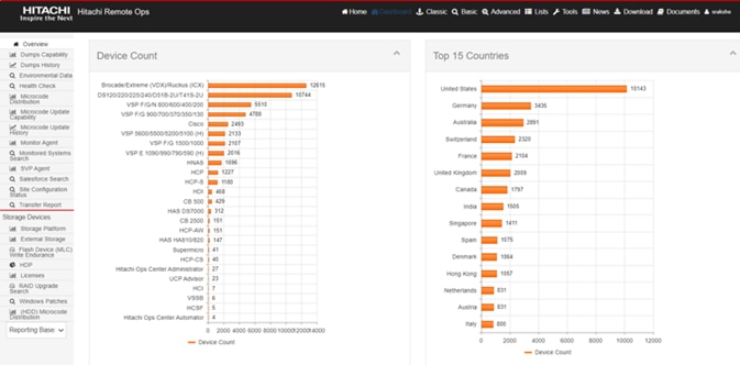
Hitachi Remote Ops monitoring system gives constant access to the full spectrum of our unmatched Global Support Center infrastructure and expertise while satisfying the highest security requirements to protect your environment.
Remote Ops can make recommendations to improve your performance. Since Remote Ops performs regular health checks to analyze errors and automatically opens a case for you when needed, Hitachi Vantara experts can contact you proactively and tune your environment remotely, while always keeping your data secure
Hitachi Remote Ops monitoring system supports the following Hitachi products as well as other third-party solutions.
Figure 32. Hitachi Remote Ops (Hi-Track)
For more information, see: https://www.hitachivantara.com/en-us/pdf/datasheet/remote-ops-monitoring-system-datasheet.pdf
VMware vSphere is the enterprise workload platform that brings the benefits of cloud to on-premises workloads. VMware vSphere aggregates the infrastructure of an entire data center to create a single powerhouse with resources that can be allocated quickly and dynamically to any application in need.
VMware vSphere 8.0 Update 1 is validated in this release and officially launches vSphere Configuration Profiles, which allow you to manage ESXi cluster configurations by specifying a desired host configuration at the cluster level, automate the scanning of ESXi hosts for compliance to the specified Desired Configuration and remediate any host that is not compliant.
VMware vSphere Configuration Profiles are featured along with the Intersight enabled Hardware Support Manager, this will require that you use vSphere Lifecycle Manager images to manage your cluster lifecycle, a vSphere 8.0 Update 1 environment, and Enterprise Plus or vSphere+ license.
For additional features enabled by VMware vSphere 8.0 U1, refer to the release notes: https://docs.vmware.com/en/VMware-vSphere/8.0/rn/vsphere-vcenter-server-801-release-notes/index.html
VMware vCenter Server
VMware vCenter Server provides centralized management of all hosts and VMs from a single HTML5 based web client and aggregates performance monitoring of clusters, hosts, and VMs. VMware vCenter Server gives administrators a deep insight into the status and configuration of compute clusters, hosts, VMs, storage, the guest OS, and other critical components of a virtual infrastructure. VMware vCenter manages the rich set of features available in a VMware vSphere environment and integrates with third party infrastructure, to include products from both Cisco and Hitachi.
This chapter contains the following:
• Physical End-to-End Connectivity
• Cisco UCS X-Series Configuration - Cisco Intersight Managed Mode
• VMware vSphere - ESXi Design
• Cisco Intersight Integration with VMware vCenter, Hitachi Storage, and Cisco Switches
• Security
The Adaptive Solutions architecture delivers a cloud-managed infrastructure solution on the latest Cisco UCS hardware featuring the Cisco UCS 6536 Fabric Interconnect and the Cisco UCS X210c M7 Compute nodes. The Virtual Server Infrastructure architecture is built to deliver the VMware vSphere 8.0 U1 hypervisor with the Hitachi Virtual Storage Platform (VSP) providing the storage infrastructure serving stateless compute through SAN boot, as well as high performance block storage for the application. The Cisco Intersight cloud-management platform is utilized to configure and manage the infrastructure, with visibility at all layers of the architecture.
This release of the Adaptive Solutions architecture uses a high-speed Fibre Channel (FC)—based storage access design, with 100G Ethernet available for the compute layer for supporting the application. In this design, the Hitachi VSP 5600 and the Cisco UCS X-Series are connected through Cisco MDS 9124V Fibre Channel Switches providing boot from SAN over the FC network, with both FC and FC-NVMe validated for VMFS datastores.
The physical connectivity details of the topology are shown in Figure 33.
Figure 33. Adaptive Solutions VSI for vSphere 8.0 U1 Physical Topology
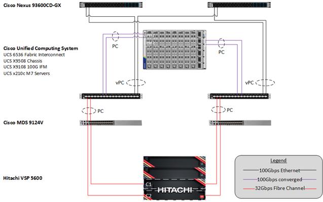
To validate the configuration, the components are set up as follows:
• Cisco UCS 6536 Fabric Interconnects provide the chassis and network connectivity.
• The Cisco UCS X9508 Chassis connects to fabric interconnects using Cisco UCS 9108-100G intelligent fabric modules (IFMs), where two 100 Gigabit Ethernet ports are used on each IFM to connect to the appropriate FI. If additional bandwidth is required, up to eight 100G ports can be utilized to the chassis.
• Cisco UCS X210c M7 Compute Nodes contain the fifth-generation Cisco 15231 virtual interface cards (VICs).
• Cisco UCS 6536 Fabric Interconnects are connected to the Cisco MDS 9124V switches using multiple 32-Gbps Fibre Channel connections (utilizing breakouts) configured as a single port channel for SAN connectivity.
• Cisco Nexus 93600CD-GX Switches in Cisco NX-OS mode provide the switching fabric.
• Cisco UCS 6536 Fabric Interconnect 100-Gigabit Ethernet uplink ports connect to Cisco Nexus 93600CD-GX Switches in a Virtual Port Channel (vPC) configuration.
• The Hitachi VSP 5600 is connected to the Cisco MDS 9124V using multiple 32Gbps Fibre Channel connections.
• VMware 8.0 U1 ESXi software is installed on Cisco UCSX-210c M7 Compute Nodes to validate the infrastructure.
Note: There are Cisco UCS C220 M7 servers mentioned in the deployment guide as an example of configuring 25GE breakouts for server connections on the Cisco UCS 6536 FI but are not otherwise featured in this design.
In the Adaptive Solutions deployment, each Cisco UCS server equipped with a Cisco Virtual Interface Card (VIC) is configured for multiple virtual Network Interfaces (vNICs) and virtual Host Based Adapters(vHBAs), which appear as standards-compliant PCIe endpoints to the OS. The end-to-end logical connectivity delivers multi-pathing for the VLAN/VSAN connectivity between the server profile for an ESXi host and the storage configuration on the Hitachi VSP 5600 is described below.
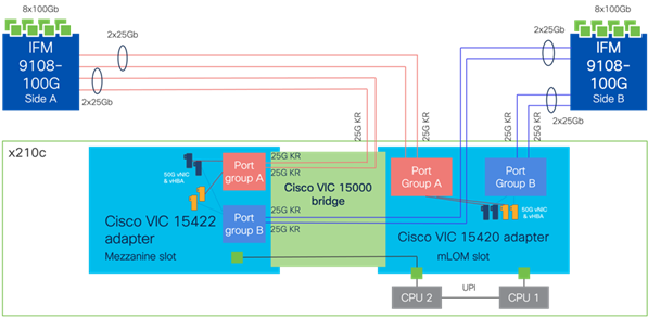
Figure 34 illustrates the end-to-end connectivity design.
Figure 34. Logical End-to-End Connectivity
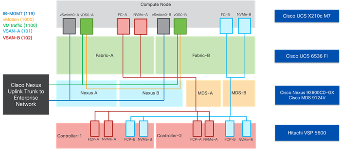
Each ESXi server profile supports:
• Managing the ESXi hosts using a common management segment
• Diskless SAN boot using FC with persistent operating system installation for true stateless computing
• The vNICs are:
◦ Two redundant vNICs (vSwitch0-A and vSwitch0-B) carry the management VLAN which is pinned to fabric A to keep ESXi management traffic primarily within fabric A. The MTU value for these vNICs is set as a Jumbo MTU (9000), but management interfaces with MTU 1500 can be placed on these vNICs.
◦ Two redundant vNICs (vDS0-A and vDS0-B) are used by vDS0 and carry VMware vMotion traffic and customer application data traffic. Like the management traffic, the vMotion traffic is pinned to fabric B to keep it contained within fabric B. The MTU for the vNICs is set to Jumbo MTU (9000), but interfaces that require MTU 1500 can be placed on these vNICs.
• Four vHBAs are:
◦ Two vHBAs (one for FC and one for FC-NVMe) defined on Fabric A to provide access to SAN-A path.
◦ Two vHBAs (one for FC and one for FC-NVMe) defined on Fabric B to provide access to SAN-B path.
• Each ESXi host (compute node) mounts VMFS datastores and vVols from the Hitachi VSP 5600 for deploying virtual machines.
VLAN Configuration
Table 1 lists VLANs configured for setting up the environment along with their usage.
| VLAN ID |
Name |
Usage |
| 2 |
Native-VLAN |
Use VLAN 2 as native VLAN instead of default VLAN (1) |
| 19 |
OOB-MGMT-VLAN |
Out-of-band management VLAN to connect management ports for various devices |
| 119 |
IB-MGMT-VLAN |
In-band management VLAN utilized for all in-band management connectivity - for example, ESXi hosts, VM management, and so on. |
| 1000 |
vMotion |
VMware vMotion traffic |
| 1100 |
VM-Traffic |
VM data traffic VLAN |
Physical End-to-End Connectivity
The physical end-to-end connectivity specific to the storage traffic is shown in Figure 35. The Fabric Interconnects create a demarcation of FCoE handling from the compute side as the VICs talk to the IFM and connect to the FIs. The server to IFM connection that the VICs participate in is a direct physical connection of KR links between the server and the IFM, differing from the previous generation of Cisco UCS 5108 Chassis where a physical KR lane structure mediated the traffic between the servers and the respective Cisco UCS IOMs.
Leaving the FIs, the traffic is converted to direct Fibre Channel packets carried within dedicated SAN port channels to the MDS. After being received by the MDS, the zoning within each MDS isolates the intended initiator to target connectivity between FC-SCSI and FC-NVMe as it proceeds to the VSP.
The specific connections as the storage traffic flows from a Cisco UCS X210c M7 server in a UCS environment to Hitachi VSP 5600 system is as follows:
• Each Cisco UCS X210c M7 server is equipped with a Cisco UCS VIC 15231 adapter that connects to each fabric at a link speed of 100Gbps.
• The link from the Cisco UCS VIC 15231 is physically connected into the Cisco UCS 9108 100G IFM as they both reside in the Cisco UCS X9508 chassis.
• Connecting from each IFM to the Fabric Interconnect with pairs of 100Gb uplinks (can be increased to up to 8 100GB connections per IFM) that are automatically configured as port channels during chassis association, which carry the FC frames as FCoE along with the Ethernet traffic coming from the chassis.
• Continuing from the Cisco UCS 6536 Fabric Interconnects, a breakout MPO transceiver that presents multiple 32G FC ports configured as a port channel into the Cisco MDS 9124V, carrying FC-SCSI and FC-NVMe traffic, for increased aggregate bandwidth and link loss resiliency.
• Ending at the Hitachi VSP 5600 Fibre Channel controller ports with dedicated F_Ports on the Cisco MDS 9124V for each N_Port WWPN of the VSP controller, with each channel board (CHB).
Figure 35. Adaptive Solutions end to end physical multi-pathing for Fibre Channel
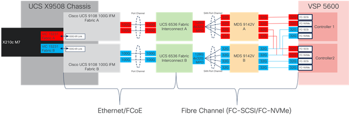
The dedicated Ethernet traffic utilizes the same links coming from the IFM into the FIs as shown in figure 37, but will communicate beyond the FIs within a pair of port channels that are received across the upstream Nexus as two separate Virtual Port Channels (vPC) that each Nexus will participate in.
As with the FC storage traffic, the Ethernet data traffic follows similar paths as follows:
• Each Cisco UCS X210c M7 server is equipped with a VIC 15231 adapter that connects to each fabric at a link speed of 100Gbps.
• The link from the VIC 15231 is physically connected into the Cisco UCS Cisco UCS 9108 100G IFM as they both reside in the X9508 chassis.
· Connecting from each IFM to a dedicated Fabric Interconnect with pairs of 100Gb uplinks (can be increased to up to 8 100GB connections per IFM) that are automatically configured as port channels during chassis association.
· Connecting out of the Fabric Interconnects, the port channels are configured with two 100Gb uplinks to the Nexus that can be expanded as needed.
Figure 36. Adaptive Solutions End-to-End Physical Multi-Pathing for Ethernet
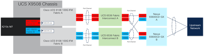
The Cisco UCS X9508 Chassis is equipped with the Cisco UCS 9108-100G intelligent fabric modules (IFMs). The Cisco UCS X9508 Chassis connects to each Cisco UCS 6536 FI using two of the eight 100GE ports, as shown in Figure 37. If you require more bandwidth, all eight ports on the IFMs can be connected to each FI.
Figure 37. Cisco UCS X9508 Chassis Connectivity to Cisco UCS Fabric Interconnects
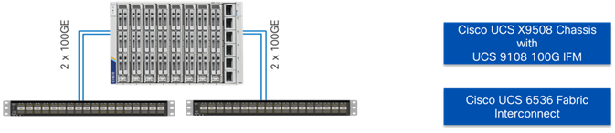
The Cisco Nexus 93600CD-GX device configuration covers the core networking requirements for Layer 2 and Layer 3 communication. Some of the key NX-OS features implemented within the design are:
• Feature interface-vans—Allows for VLAN IP interfaces to be configured within the switch as gateways.
• Feature HSRP—Allows for Hot Standby Routing Protocol configuration for high availability.
• Feature LACP—Allows for the utilization of Link Aggregation Control Protocol (802.3ad) by the port channels configured on the switch.
• Feature VPC—Virtual Port-Channel (vPC) presents the two Nexus switches as a single “logical” port channel to the connecting upstream or downstream device.
• Feature LLDP—Link Layer Discovery Protocol (LLDP), a vendor-neutral device discovery protocol, allows the discovery of both Cisco devices and devices from other sources.
• Feature NX-API—NX-API improves the accessibility of CLI by making it available outside of the switch by using HTTP/HTTPS. This feature helps with configuring the Cisco Nexus switch remotely using the automation framework.
• Feature UDLD—Enables unidirectional link detection for various interfaces.
Cisco UCS Fabric Interconnect 6536 to Cisco Nexus 93600CD-GX Ethernet Connectivity
Cisco UCS 6536 FIs are connected with port channels to Cisco Nexus 93600CD-GX switches using 100GE connections configured as virtual port channels. Each FI is connected to both Cisco Nexus switches using a 100G connection; additional links can easily be added to the port channel to increase the bandwidth as needed. Figure 38 illustrates the physical connectivity details.
Figure 38. Cisco UCS 6536 FI Ethernet Connectivity
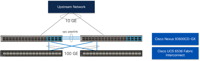
Upstream connections for the Cisco Nexus 93600CD-GX can support up to 400G links, however for the validated environment, 10G connections were used with QSA modules.
The Cisco MDS 9124V delivers 32Gbps Fibre Channel (FC) capabilities to the Adaptive Solutions design that is future proofed with 64Gbps capability. A redundant 32 Gbps Fibre Channel SAN configuration is deployed utilizing two Cisco MDS 9124Vs switches. Some key MDS features implemented within the design are:
• Feature NPIV—N port identifier virtualization (NPIV) provides a means to assign multiple FC IDs to a single N port.
• Feature fport-channel-trunk—F-port-channel-trunks allow for the fabric logins from the NPV switch to be virtualized over the port channel. This provides nondisruptive redundancy should individual member links fail.
• Enhanced Device Alias – a feature that allows device aliases (a name for a WWPN) to be used in zones instead of WWPNs, making zones more readable. Also, if a WWPN for a vHBA or Hitachi VSP port changes, the device alias can be changed, and this change will carry over into all zones that use the device alias instead of changing WWPNs in all zones.
• Smart-Zoning—a feature that reduces the number of TCAM entries and administrative overhead by identifying the initiators and targets in the environment.
Cisco UCS Fabric Interconnect 6536 to Cisco MDS 9124V SAN Connectivity
For SAN connectivity, each Cisco UCS 6536 Fabric Interconnect is connected to a Cisco MDS 9124V SAN switch using a breakout on ports 33-36 to a 4 x 32G Fibre Channel SAN port-channel connection, as shown in Figure 39.
Figure 39. Cisco UCS 6536 FI to Cisco MDS 9124V SAN Connectivity
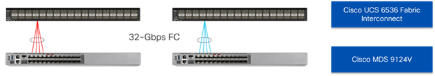
Fibre Channel connectivity within the SAN port-channel will carry both FC-SCSI and FC-NVMe traffic that are separated by dedicated zones within the MDS for FC-SCSI vs FC-NVMe initiators to targets.
Hitachi VSP 5600 to MDS 9124V SAN Connectivity
For SAN connectivity, each Hitachi VSP 5600 controller is connected to both of the Cisco MDS 9124V SAN switches using 32G Fibre Channel connections, as shown in Figure 40.
Figure 40. Hitachi VSP 5600 to Cisco MDS 9124V SAN Connectivity
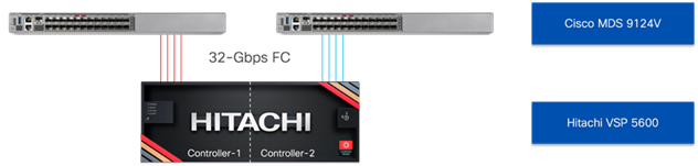
Fibre Channel connectivity from the Cisco MDS to the Hitachi VSP 5600 is separated within the MDS by dedicated zones for the FC-SCSI vs FC-NVMe initiators to targets but are also physically separated on the controllers with certain ports dedicated to FC-SCSI vs FC-NVMe.
Cisco UCS X-Series Configuration - Cisco Intersight Managed Mode
Cisco Intersight Managed Mode standardizes policy and operation management for Cisco UCS X-Series and the remaining UCS hardware used in this CVD. The Cisco UCS compute nodes are configured using server profiles defined in Cisco Intersight. These server profiles derive all the server characteristics from various policies and templates. At a high level, configuring Cisco UCS using Intersight Managed Mode consists of the steps shown in Figure 41.
Figure 41. Configuration Steps for Cisco Intersight Managed Mode
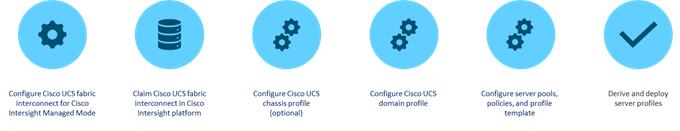
Set up Cisco UCS Fabric Interconnect for Cisco Intersight Managed Mode
During the initial configuration, for the management mode the configuration wizard enables customers to choose whether to manage the fabric interconnect through Cisco UCS Manager or the Cisco Intersight platform. Customers can switch the management mode for the fabric interconnects between Cisco Intersight and Cisco UCS Manager at any time; however, Cisco UCS FIs must be set up in Intersight Managed Mode (IMM) for configuring the Cisco UCS X-Series system and the Cisco UCS 6536 fabric interconnects. Figure 42 shows the dialog during initial configuration of Cisco UCS FIs for setting up IMM.
Figure 42. Fabric Interconnect Setup for Cisco Intersight Managed Mode
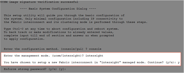
Claim a Cisco UCS Fabric Interconnect in the Cisco Intersight Platform
After setting up the Cisco UCS fabric interconnect for Cisco Intersight Managed Mode, FIs can be claimed to a new or an existing Cisco Intersight account. When a Cisco UCS fabric interconnect is successfully added to the Cisco Intersight platform, all future configuration steps are completed in the Cisco Intersight portal.
Figure 43. Cisco Intersight: Fabric Interconnects
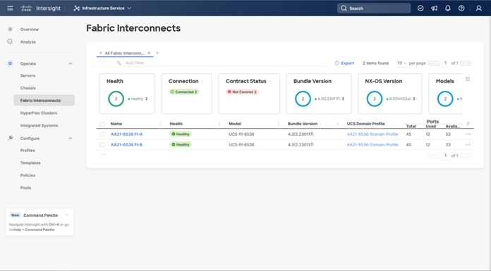 You can verify whether a Cisco UCS fabric interconnect is in Cisco UCS Manager managed mode or Cisco Intersight Managed Mode by clicking the fabric interconnect name and looking at the detailed in-formation screen for the FI, as shown in Figure 44.
![]()
Figure 44. Cisco UCS FI in Intersight Managed Mode
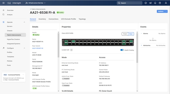
Cisco UCS Chassis Profile (Optional)
A Cisco UCS Chassis profile configures and associate chassis policy to an IMM claimed chassis. The chassis profile feature is available in Intersight only if customers have installed the Intersight Essentials License. The chassis-related policies can be attached to the profile either at the time of creation or later.
The chassis profile is used to set the power policy for the chassis. By default, Cisco UCS X-Series power supplies are configured in GRID mode, but the power policy can be utilized to set the power supplies in non-redundant or N+1/N+2 redundant modes.
Cisco UCS Domain Profile
A Cisco UCS domain profile configures a fabric interconnect pair through reusable policies, allows configuration of the ports and port channels, and configures the VLANs and VSANs to be used in the network. It defines the characteristics of and configures the ports on the fabric interconnects. One Cisco UCS domain profile can be assigned to one fabric interconnect domain, which will be associated with one port policy per Cisco UCS domain profile.
Some of the characteristics of the Cisco UCS domain profile in the environment are:
• A single domain profile is created for the pair of Cisco UCS fabric interconnects.
• Unique port policies are defined for the two fabric interconnects.
• The VLAN configuration policy is common to the fabric interconnect pair because both fabric interconnects are configured for the same set of VLANs.
• The VSAN configuration policies are unique for the two fabric interconnects because the VSANs are unique.
• The Network Time Protocol (NTP), network connectivity, Link Control (UDLD), and system Quality-of-Service (QoS) policies are common to the fabric interconnect pair.
After the Cisco UCS domain profile has been successfully created and deployed, the policies including the port policies are pushed to the Cisco UCS fabric interconnects. The Cisco UCS domain profile can easily be cloned to install additional Cisco UCS systems. When cloning the UCS domain profile, the new UCS domains utilize the existing policies for consistent deployment of additional Cisco UCS systems at scale.
Figure 45. Cisco UCS Domain Profile
The Cisco UCS X9508 Chassis and Cisco UCS X210c M7 Compute Nodes are automatically discovered when the ports are successfully configured using the domain profile as shown in Figure 46, Figure 47, and Figure 48.
Figure 46. Cisco UCS X9508 Chassis Front View
Figure 47. Cisco UCS X9508 Chassis Rear View
Figure 48. Cisco UCS X210c M7 Compute Nodes
Server Profile Template
A server profile template enables resource management by simplifying policy alignment and server configuration. A server profile template is created using the server profile template wizard. The server profile template wizard groups the server policies into the following categories to provide a quick summary view of the policies that are attached to a profile:
• Compute policies: UUID pool, BIOS, boot order, and virtual media policies. (Firmware, Power, and Thermal polices are not used in this design)
• Management policies: Integrated Management Controller (IMC) Access, Intelligent Platform Management Interface (IPMI) over LAN, and virtual Keyboard, Video, and Mouse (KVM) policies. (Certificate Management, Local User, Serial over LAN (SOL), Simple Network Management Protocol (SNMP), and Syslog policies are not used in this design)
• Storage policies: With a SAN boot design, these policies are not used, but will be relevant for accessing any storage local to the compute node.
• Network policies: adapter configuration, LAN connectivity, and SAN connectivity policies.
Note: The LAN connectivity policy requires you to create Ethernet network policy, Ethernet adapter policy, and Ethernet QoS policy.
Note: The SAN connectivity policy requires you to create Fibre Channel (FC) network policy, Fibre Channel adapter policy, and Fibre Channel QoS policy. SAN connectivity policy is only required for the FC connectivity option.
Some of the characteristics of the server profile template are as follows:
• BIOS policy is created to specify various server parameters in accordance with UCS VSI best practices and Cisco UCS Performance Tuning Guides.
• Boot order policy defines virtual media (KVM mapped DVD), the FC SAN paths, and a CIMC mapped DVD for OS installation.
• IMC access policy defines the management IP address pool for KVM access.
• LAN connectivity policy is used to create four virtual network interface cards (vNICs); two for management virtual switches (vSwitch0) and two for application vSphere Distributed Switch (vDS); along with various policies and pools.
• SAN connectivity policy is used to create four virtual host bus adapters (vHBAs); two each (FC and FC-NVMe) for SAN A and for SAN B; along with various policies and pools.
Figure 49 shows various policies associated with the server profile template.
Figure 49. Server Profile Template
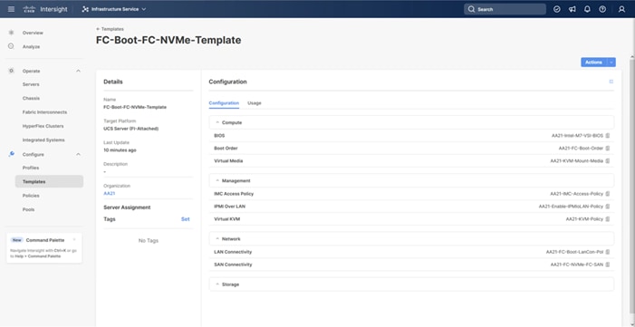
Derive and Deploy Server Profiles from the Cisco Intersight Server Profile Template
The Cisco Intersight server profile allows server configurations to be deployed directly on the compute nodes based on polices defined in the server profile template. After a server profile template has been successfully created, server profiles can be derived from the template and associated with the Cisco UCS Compute Nodes, as shown in Figure 50.
Figure 50. Deriving a Server Profile from Templates
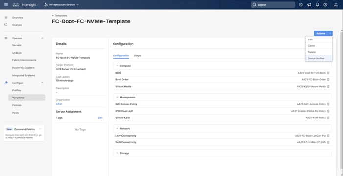
On successful deployment of the server profile, the Cisco UCS Compute Nodes are configured with parameters defined in the server profile and can boot from the storage LUN hosted from the Hitachi VSP 5600.
Cisco UCS Ethernet Adapter Policies
The processing of Ethernet packet can be adjusted within Cisco UCS to use of Cisco UCS Ethernet Adapter policies to optimize network traffic into multiple receive (RX) queues and maximize the use of multiple CPU cores in servicing these queues resulting in higher network throughput on up to 100Gbps interfaces. IMM (and UCSM) adapter policies allow the number of transmit (TX) and RX queues and the queue ring size (buffer size) to be adjusted, and features such as Receive Side Scaling (RSS) to be enabled. RSS allows multiple RX queues to each be assigned to a different CPU core, allowing parallel processing of incoming Ethernet traffic.
VMware ESXi 8.0 U1 supports RSS, a single TX queue, and up to 16 RX queues. This CVD introduces the fifth-generation Cisco VICs which support a ring size up to 16K (16,384), where the previous fourth-generation VICs support a ring size up to 4K (4096). Increasing the ring size can result in increased latency, but with the higher speed 100Gbps interfaces used in this CVD, the data moves through the buffers in less time, minimizing the latency increase. In this CVD, two Ethernet Adapter policies are defined, with additional policies with higher ring sizes possible for environments incorporating IP based storage.
Table 2. Cisco UCS Ethernet Adapter Policy specifics
| Policy Name |
TX Queues |
TX Ring Size |
RX Queues |
RX Ring Size |
RSS |
| VMware-Default |
1 |
256 |
1 |
512 |
Disabled |
| VMware-HighTraffic |
1 |
4096 |
8 |
4096 |
Enabled |
Figure 51 shows part of the VMware-High-Trf Ethernet Adapter policy in Cisco Intersight. For more information on configuring Ethernet Adapter polices, see: https://www.cisco.com/c/en/us/products/collateral/interfaces-modules/unified-computing-system-adapters/white-paper-c11-744754.html.
Figure 51. VMware-High-Trf Ethernet Adapter Policy
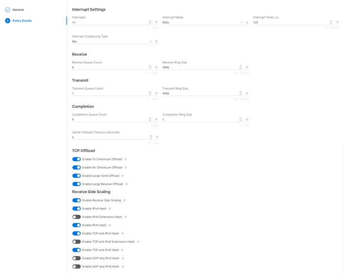
Each VSP storage system is comprised of multiple controllers and Fibre Channel adapters that control connectivity to the Fibre Channel fabrics via the MDS FC switches. Channel boards (CHBs) are used within the VSP 5600 models and have two controllers contained within the storage system. The multiple CHBs within each storage system allow for designing multiple layers of redundancy within the storage architecture, increasing availability, and maintaining performance during a failure event.
The VSP 5600, CHBs each contain up to four individual Fibre Channel ports, allowing for redundant connections to each fabric in the Cisco UCS infrastructure. The VSP CHBs each contain up to four individual Fibre Channel ports, allowing for redundant connections to each fabric in the Cisco UCS infrastructure. In this deployment 4 ports are configured for FC-SCSI protocol, one from controller 1 (CL1-A) and one from controller 2 (CL2-A) going into MDS fabric A, as well as one from controller 1 (CL3-A) and one from controller 2 (CL4-A) going into MDS fabric B for a total of 4 connections. These connections provide the data path to boot LUNs and VMFS datastores that utilize FC-SCSI protocol. Additionally, 4 ports are configured for FC-NVMe, one from controller 1 (CL1-B) and one from controller 2 (CL2-B) going into MDS fabric A, and one from controller 1 (CL3-B) and one from controller 2 (CL4-B) going into MDS fabric B to provide an additional data path for VMFS datastores that utilize the FC-NVMe protocol.
With the Cisco UCS ability to provide alternate data paths each, Fibre Channel fabric provides total of 16 paths, with four paths to each host which hold boot LUN as well as for VMFS datastores per host, comprised of two paths on each fabric. If you plan to deploy VMware ESXi hosts, each host’s WWN should be in its own host group. This approach provides granular control over LUN presentation to ESXi hosts. This is the best practice for SAN boot environments such as Cisco UCS, because ESXi hosts do not have access to other ESXi hosts’ boot LUNs.
Figure 52. Logical View of LUNs to VSP 5600 Port Association
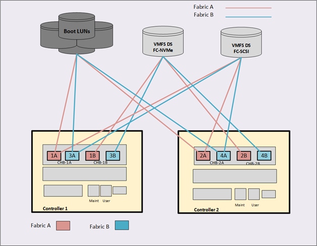
Hitachi Storage Provider for VMware vCenter
Hitachi Storage Provider for VMware vCenter (Storage Provider for VMware vCenter) allows you to use the following VMware APIs for Storage Awareness (VASA) features with Hitachi storage systems:
• VMware vSphere Virtual Volumes (vVols)
• VMware Virtual Machine File System (VMFS) via VMware Storage Policy Based Management (SPBM)
Configure the Protocol Endpoint
The protocol endpoint (PE) is an LDEV used by a VMware ESXi host to access a VSP storage system. On the storage system, the PE is known as the administrative logical unit (ALU).
The PE must be attached to an ESXi host in order to use vVols. Hitachi VSP Storage Navigator is used to create PEs with the provisioning type ALU and assigns them to a VMware ESXi host. When an ALU has been assigned to your respective VMware ESXi hosts, you must register the VASA storage provider within the VMware vSphere Web Client. A PE must be assigned to each ESXi host within a vVol environment, within this design the protocol endpoints are allocated to the same hostgroups as the FC-SCSI VMFS datastores that use ports CL1-A, CL2-A for fabric A and CL3-A, CL4-A for fabric B.
Configure the Hitachi VSP
Storage Navigator must be used to create the following:
• Protocol Endpoint (ALU)
• vVols Resource Group
• Dynamic provisioning pools (Can also be configured via Ops Center Administrator)
• Hitachi Thin Image pools (Can also be configured via Ops Center Administrator)
To create virtual volumes (vVols), VSP storage must be setup with system resources and resource groups. vVols use dynamic provisioning pools to store virtual machine data and use pools created by Hitachi Thin Image to store snapshot data. A vVol virtual machine configuration file uses multiple LDEV IDs to create a 1:1 correspondence with the LUNs. These resources are collected and made available as a single logical resource group.
Register the Storage System in VASA
After you have deployed the VASA provider within your virtual environment, onboard and register the storage system that will provide the backend storage to VASA.
Create a Storage Container and Define a Capability Profile
With VASA, each vVols storage container corresponds to a storage system resource group containing dynamic provisioning pools, optional pools made with Hitachi Thin Image, and LDEV IDs. To use vVols, you must create a storage container corresponding to the storage system's resource group and set capability profiles for each dynamic provisioning pool in the group. Profiles for storage containers push storage attributes to the VMware administrator to view within VMware vSphere.
Define a Virtual Machine Storage Profile
When configuring the VASA Provider, VMware administrators must create a virtual machine storage policy based on the capabilities that are pushed down from the VASA Provider. These attributes can be based on cost, RAID level, pool type, tiers, location, and data protection capabilities.
Deploy a vSphere Virtual Volumes (vVols) Datastore
After you have successfully registered and configured the VASA Provider, you can implement a vVols datastore with FC-SCSI protocol that VMs can leverage.
Figure 53. VASA provider with vVols from VSP 5600 storage
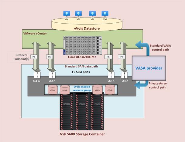
Hitachi Ops Center Administrator
Within this design, Hitachi Ops Center Administrator was used to configure the VSP 5600 to provide boot LUNs and VMFS datastores to the VSI infrastructure hosted on the Cisco UCS.
You can perform the following operations from the Hitachi Ops Center Administrator (Figure 54):
Figure 54. Hitachi Ops Center Administrator
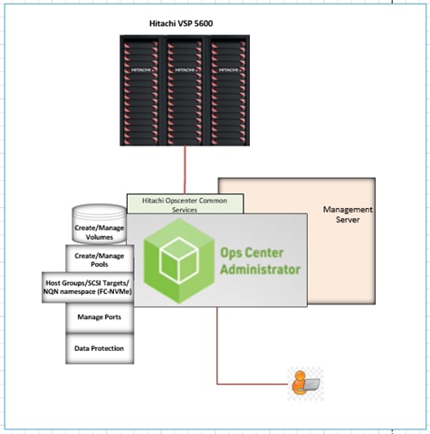
The following are the operations performed through Hitachi Ops Center Administrator:
• Initialization of Parity groups
Parity groups are the basic units of storage capacity. Creating parity groups converts the raw disk capacity in your storage system into usable capacity. Via Administrator the parity group can be initialized to a basic LDEV which can be now used for pool creation of HDP or HDT.
Note: For VSP 5600 series, Parity groups cannot be created via Ops Center Administrator, but can be initialized in Ops Center Administrator.
If you choose to use the basic method to create parity groups, Ops Center Administrator automatically reviews the available spare disks and allocates more spare disks if needed. If you choose to create parity groups using the advanced method, you should review the number of spare disks in the parity groups inventory summary. To assign more or fewer spare disks, use disk management.
• Creating a boot and application pool
When parity groups have been initialized, pools can be created in order to provide thin provisioned volumes for host or application use, there are two different options to create a pool. i.e. basic and advanced. When creating a pool, use the basic option to take advantage of tiers that are based on best practices. If you want more flexibility and do not need to take advantage of best practices, you can use the advanced option to select specific parity groups.
The pool types are as follows:
• HDP (Dynamic Provisioning), which allocates virtual volumes to a host and uses the physical capacity that is necessary according to the data write request.
• Tiered, which is used with Dynamic Provisioning and places data in a hardware tier according to the I/O load. For example, a data area that has a high I/O load is placed in a high-speed hardware tier, and a data area that has a low I/O load is placed in a low-speed hardware tier.
• Optional: HTI (Thin Image), which stores snapshot data in pools. A pool consists of multiple pool-VOLs. The pool-VOLs contain the snapshot data. A pool can contain up to 1,024 pool-VOLs.
Within this design, HDP pools were utilized to provide both boot LUNs and VMFS datastores to VSI infrastructure.
• Managing port security and settings
Before Ops Center Administrator can create a host storage domain (HSD) on a port, you may need to change the port security and settings like port attributes. For example, port security must be enabled for Fibre or iSCSI ports. By default, security is disabled on supported storage systems. If port security is disabled, Ops Center Administrator does not select the port for host storage domain (HSD) creation.
To provision volumes based on FC-SCSI and FC-NVMe ports in Ops Center Administrator, set the following:
◦ For Fibre with SCSI mode ports: Enable Security
◦ For Fibre with NVMe mode ports: Disable Security
• Server and server groups inventory
With Hitachi Ops Center Administrator, you can utilize the concept of servers to onboard the Cisco UCS servers used to support VSI. Servers can be added by defining their HBA WWNs related to fabric A and fabric B for both FC-SCSI and FC-NVMe, as well as in the case of FC-NVMe host NQN identifier. This definition will create the traditional host group on the Hitachi VSP as well as namespace used for FC-NVMe protocol. Once servers have been onboarded, they can be placed in server groups for easy one click allocation of boot LUNs for VMFS datastores to the entire cluster.
While attaching volume to Server or Server group below are the setting for Host mode options (HMOs) and Host mode needs to be selected with protocol as FC-SCSI:
◦ Host mode: 63 ((VAAI) Support Option for vStorage APIs based on T10 standards) must be enabled
◦ Host mode: 21 VMware Extension since Host operating system is VMware server with LUSE volume support.
Figure 55. FC-SCSI storage logical provisioning
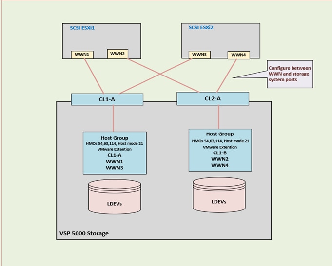
While attaching volume to Server or Server group Host mode VMware extension (EX) needs to be selected with protocol FC-NVMe. With FC-NVMe, NQNs do not replace FC WWNs–they both exist. The WWN of each side is what is advertised on the FC layer to enable physical connectivity and zoning. The NQN is what enables the NVMe layer to communicate to the correct Fibre Channel endpoints. To abstract ESXi host NQNs administrators are required to run the following command:
#esxcli nvme info get
Figure 56. FC-NVMe storage logical provisioning
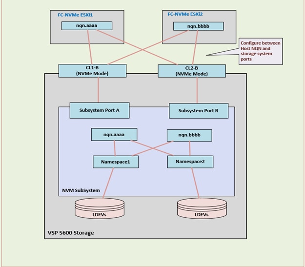
The VMware vSphere design incorporates concepts and best practices from VMware, Cisco, and Hitachi in setting up ESXi hosts on Cisco UCS servers to deliver reliability and performance of those servers to the Hitachi storage and Cisco Nexus network they connect to.
ESXi VIC Virtual Adapters
Multiple vNICs (and vHBAs) are created for the ESXi hosts using the Cisco Intersight server profile using the Cisco VIC 15231 adapters and are then assigned to specific virtual and distributed switches. The vNIC and vHBA distribution for the ESXi hosts is as follows:
• Two vNICs (one on each fabric) for the VMware virtual switch vSwitch0 to support the in-band management traffic. The port group for the management traffic is pinned to UCS Fabric A to reduce the need to leave the fabric for management communication between the ESXi hosts. The standard VMware-Default Cisco UCS Ethernet adapter policy is assigned to these vNICs.
• Two vNICs (one on each fabric) for the VMware vSphere Distributed Switch (vDS) vDS0 to support customer data traffic and vMotion traffic. In this vDS, VMware vMotion is pinned to UCS Fabric B ensuring vMotion is switched in the B-side fabric interconnect for the same traffic concentrations reasons that keeps management traffic isolated to Cisco UCS Fabric A. The higher performance VMware-HighTraffic Cisco UCS Ethernet adapter policy configured within this design uses Receive Side Scaling (RSS) and is assigned to these vNICs.
• Two vHBAs (one on each fabric) for standard Fibre Channel (FC) traffic. This specifically includes the SAN boot of the Cisco UCS X210c with the installed ESXi instances, but a validation of FC for virtual volumes (vVols) and VMFS datastores was conducted.
• Two vHBAs (one on each fabric) for Fibre Channel over NVMe (FC-NVMe) are configured for the ESXi hosts to utilize high performance FC-NVMe connectivity.
• Within this validated VSI architecture, the vNICs are presented as 100G virtual connections and the vHBAs are presented as 64G virtual connections.
Figure 57 shows the ESXi virtual adapter configurations in detail.
Figure 57. Figure 59 VMware vSphere - ESXi Host Networking
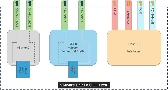
vSphere Configuration Profiles
vSphere Configuration Profiles is a new production feature in VMware vSphere 8.0 U1 that has replaced Host Profiles within vSphere. After the first host has been setup, additional hosts can be consistently added with vSphere Configuration Profiles. Remediation is handled through the extraction of a json file from a reference host for the cluster. This reference host will have gone through a basic configuration once added to vCenter, adjusting settings, such as NTP, Power, Datastore access, VMkernel creation, and vDS membership.
With the extracted json, snippets can be created for the additional hosts copied from the reference host and are brought back into the “host-specific” section.
Figure 58. Editing the exported host configuration profile json to include additional hosts
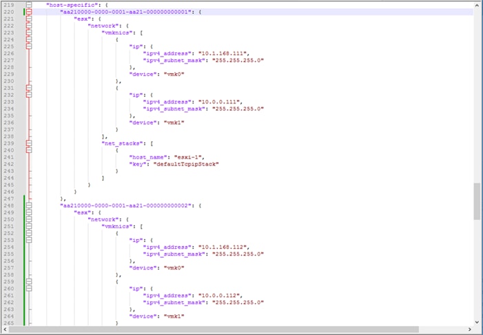
The adjusted json file is then imported back in for the cluster and a compliance is run to adjust the added hosts to the common configurations and host specific settings that are contained within the json file.
Cisco Hardware Support Manager (HSM) for VMware vCenter Integration with Cisco Intersight
The Cisco Hardware Support Manager (HSM) is enabled by the connection from the VMware vCenter through the Cisco Intersight Assist to be used within vSphere Lifecycle Manager (vLCM). This provides the ability to update the operating system drivers (VIBs) and perform firmware upgrades simultaneously with a single firmware image allowing for image consistency at a cluster level.
Figure 59. ESXi Custom Image for Cisco with updated firmware and drivers within vLCM
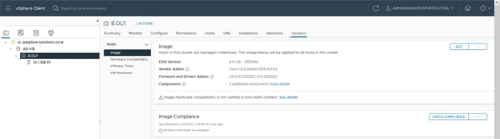
The Cisco Intersight HSM becomes available within vLCM after the VMware vCenter is added as a target within Cisco Intersight from Cisco Intersight Assist providing firmware and driver as updates for the cluster.
Figure 60. Intersight Hardware Support Manager selected within vLCM
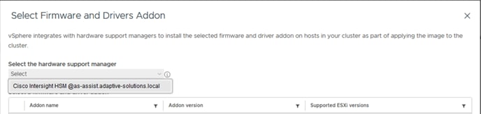 Cluster compliance with the image is tracked, and individual hosts can be updated within vLCM and automatically rebooted to bring them into compliance.
Cisco Intersight Integration with VMware vCenter, Hitachi Storage, and Cisco Switches
Hitachi storage and VMware vCenter connect to Cisco Intersight using third-party device connectors, and Cisco Nexus and MDS switches using a Cisco device connector. Cisco Intersight Assist virtual appliance enables Cisco Intersight to communicate with both non-Cisco devices and supported Cisco switches because third-party infrastructure does not contain any built-in Cisco Intersight device connector. Cisco Intersight uses:
• The device connector running within the Cisco Intersight Assist virtual appliance to communicate with the VMware vCenter.
• The device connector running within a Cisco Intersight Assist virtual appliance to connect with the Hitachi Ops Center API Configuration Manager to integrate with the Hitachi VSP.
• The device connector running within the Cisco Intersight Assist virtual appliance to communicate with Cisco Nexus 9000 and MDS switches.
Note: A single Cisco Intersight Assist virtual appliance can support Hitachi VSP storage, VMware vCenter, and Cisco switches.
Figure 61. Intersight Assist for presenting Cisco and Hitachi Infrastructure
Cisco Intersight integration with VMware vCenter, Hitachi VSP, and Cisco switches enables customers to perform the following tasks right from the Cisco Intersight dashboard:
• Monitor the virtualization, storage, and switching environment.
• Add various dashboard widgets to obtain useful at-a-glance information.
• Perform common Virtual Machine tasks such as power on/off, remote console and so on.
• Orchestrate virtual, storage, and switching, environment to perform common configuration tasks.
The Adaptive Solutions architecture enables customers to use new management capabilities with no compromise in their existing Hitachi VSP, VMware, and switch operations. IT users will be able to manage heterogeneous infrastructure from a centralized Cisco Intersight portal. At the same time, the IT staff can continue to use Hitachi VSP, VMware vCenter, and Cisco Switch Interfaces for comprehensive analysis, diagnostics, and reporting of virtual, storage, and switching environments.
Obtain Storage-level Information
With the Cisco Intersight Assist deployed and connected to the Intersight SaaS platform, the Hitachi VSP can be brought into visibility from a connection with the Hitachi Ops Center API Configuration Manager and Cisco Intersight Assist.
Figure 62. Hitachi VSP 5600 Information in Cisco Intersight
Obtain VMware vCenter and Cisco Switch Information
After successfully claiming the VMware vCenter and supported Cisco switches as targets, customers can also view information on these products in Cisco Intersight.
Figure 63. VMware vCenter Information in Cisco Intersight
Figure 64. Cisco Nexus Information in Cisco Intersight
Figure 65. Cisco MDS Information in Cisco Intersight
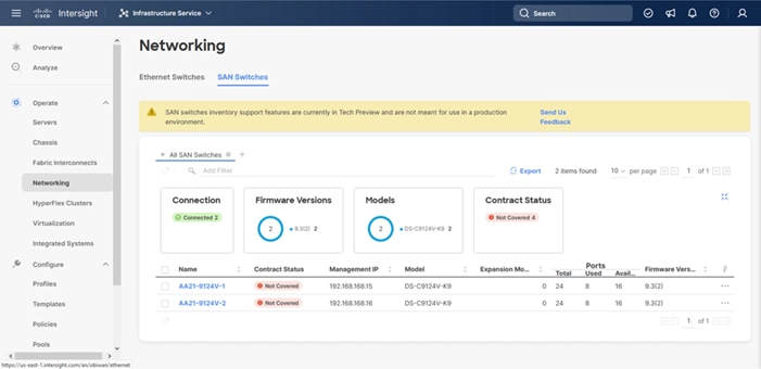
Detailed views of the VMware vSphere subcomponents and the added switches are available by selecting the left-side menu options and listed targets.
All components in the Adaptive Solutions design are built to create a secure infrastructure, accessible only by those who need it within their operational categories.
Cisco Intersight
Cisco Intersight supports SSO (Single-Sign-On), along with RBAC controls to structure access and permissions to managed resources. With Cisco UCS overseen by Intersight Managed Mode, all servers become centrally maintained by consistent access policies which are secured by default:
• SSH (TCP port 22) – Encrypted and enabled by default (it cannot be disabled)
• HTTPS (TCP port 443) – Encrypted (OpenSSL-based)
• KVM Management (TCP port 2068) – Encrypted (RC4)
Figure 66. Security and access for Cisco Intersight overseeing Cisco and Hitachi infrastructure
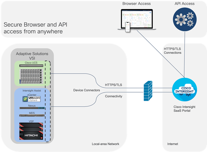
Within the Cisco UCS platform, the Cisco UCS X-Series servers also support an optional Trusted Platform Module (TPM) and UEFI Secure Boot. Additional security features include a secure boot FPGA and ACT2 anticounterfeit provisions.
In the design, operational components are separated by in-band and out-of-band networks to insulate traffic as needed. Zoning within VSANs restricts FC traffic to designated targets and initiators as a base level of isolation. Cisco Nexus and MDS both support RBAC, TACACS+, RADIUS and direct LDAP, for structuring permissions and ensuring secure access. Information on further securing Cisco Nexus and MDS switches can be found here:
https://sec.cloudapps.cisco.com/security/center/resources/securing_nx_os.html#_Toc303633207
Hitachi
Some of the security features in the Hitachi VSP include:
• Protection from unauthorized access - All VSP 5000 series models are hardened to prevent any leaks of physical data and unauthorized system access. This enables you to protect sensitive data from unauthorized access, meet stringent data privacy requirements, and adhere to strict regulatory compliance policies. Additional measures are available to ensure quick recovery from ransomware attacks.
• Data Security for VSP Storage System - Hitachi storage systems provide the following features to protect sensitive data from unauthorized access, meet stringent data privacy requirements, and adhere to strict regulatory compliance policies:
◦ Data-at-rest encryption - The Encryption License Key feature provides hardware-based Advanced Encryption Standard (AES) encryption that enables you to implement and manage data-at-rest encryption for sensitive data on your storage system.
◦ Data retention Utility - The Data Retention Utility feature enables you to protect your data volumes from read and/or write operations and define the data retention term for the protected volumes.
◦ Volume Shredder - The Volume Shredder feature enables you to shred data after the prescribed retention period ends. This function erases the data by overwriting it with dummy data to prevent the deleted data from being restored.
VMware vSphere
VMware vSphere 8.0 U1 brings improvements including the addition of an SSH timeout on ESXi hosts, a TPM Provisioning policy allowing a vTPM to be replaced when cloning VMs, and TLS 1.2 as the minimum supported TLS version.
VMware vCenter supports SSO, configurable to an Active Directory server allowing RBAC for differentiated access levels and centralized account management. Firewall settings for hosts, access using SSH and, lockdown mode can be set consistently at the cluster level using configuration profiles. Prompt remediation of security updates can also be easily managed through VMware vSphere Lifecycle Manager.
More information on VMware vSphere security best practices can be found here: https://core.vmware.com/vmware-vsphere-8-security-configuration-guide
Data centers around the world currently account for 1 percent of the global electricity consumption, with this percentage doubling for total amount consumed within US, making them a considerable factor to energy consumption. Among the various components within a data center, servers are identified to consume the largest share of the electricity. According to Gartner, the proportion of the overall data center power budget allocated to storage is expected to double by 2030, rising from less than 20 percent in 2020 to nearly 40 percent.
Figure 67. Energy breakdown within a data center
Reducing datacenter power consumption is an important goal, and the Adaptive Solutions design offers several implementations and options to address sustainability, some of which are detailed below.
Sustainable Design
One key approach is to focus on a modern, sustainable design while striving to increase overall efficiency. Data center consolidation, modernization and maximizing rack utilization are crucial steps to achieve this goal.
Replacing older servers with advanced models, such as the Cisco UCS M7 servers introduced in this solution can significantly improve performance and achieve higher virtual machine (VM) consolidation ratios compared to previous generations, while continuing to provide more flexibility and increased performance to support new and evolving applications. The Cisco UCS M7 servers can handle more workloads with a 4-to-1 consolidation ratio compared to the previous generation of servers.
The Cisco UCS X-9508 used in this solution, provides a future-ready platform with the density and efficiency of blade servers and the expandability and flexibility of rack servers. The modular, chassis-based design allows you to share resources (chassis enclosure, switching fabric, power, and cooling) among multiple servers for a more efficient utilization of rack space, power, and cooling, while maintaining the flexibility to expand capabilities as needed. The Cisco UCS-X9508 7-RU chassis supports up to 8 compute nodes with unified connectivity and management. Each compute node can also support up to 6 Solid-State Drives (SSDs), or Non-Volatile Memory Express (NVMe) drives for a total of ~90TB of local storage using 15.3TB NVMe drives available today. For AI/ML, VDI and other compute-intensive workloads, you can add NVIDIA and Intel Flex GPUs to the Cisco UCS X-Series chassis, directly on each compute node or using a dedicated PCIe (X440p) node. Cisco UCS-X9508 can support up to 16 GPUs using the X440p PCIe nodes, with the option to add an additional two GPUs on the compute nodes. Cisco UCS X-Series is also designed for the next decade of computing, with the ability to support new technologies as they evolve and mature such as PCI Gen5.0, CXL and liquid cooling for a more efficient data center.
Sustainable Components
Hitachi Virtual Storage Platform and Cisco UCS X-Series platform used in this solution are committed to sustainability in their design and implementation of both products. These are critical tools for enterprises as they modernize their data centers and select infrastructure to consolidate their workloads.
Cisco UCS X-Series Platform Sustainability
The Cisco UCS X-Series platform is designed with several energy efficient features to optimize power and cooling as outlined below. Cisco UCS X-Series was recently awarded the 2023 SEAL Sustainable Product Award for products that are “purpose-built” for a sustainable future.
• Cisco UCS X-Series chassis uses a more open design for less air impedance and minimal air-handling material to reduce the overall resources that need to be sourced and installed within the system.
• It is equipped with modular, titanium-rated power supply units (PSUs) and 54-volt DC-power delivery system that minimizes the many internal power conversions, internal copper cabling needed, and amperage – saving in both overhead and power loss.
• The Cisco UCS X-Series has modular counter-rotating fans with wider apertures and high cubic feet per minute (CFM). It also has innovative zone-based cooling to optimize only those components needing more handling. With an innovative fan speed algorithm, an industry first, the Cisco UCS X-Series can optimize power consumption and minimize hysteresis to prevent fan speed overshot and reduce overall fan power consumption.
• The architecture of the Cisco UCS X-Series can extend the useful life of server elements using a mid-plane-less design to disaggregate components, with the ability to support new high-speed interconnects in the future and extend the refresh cycle of components.
For Cisco UCS X-Series servers, server power usage is displayed under the server’s Statistics tab for various customizable intervals as shown below. By enabling Intelligent Platform Management Interface (IPMI) over LAN policy on each server, power usage and other metrics can be queried from IPMI over LAN, allowing multiple management components (for example, VMware vCenter and Cisco Intersight) to monitor and provide a broader picture of the power consumption over time from a server and workload perspective. Alternatively, you can also use Redfish to query server power usage when managing the servers in Intersight Managed Mode.
Figure 68. Cisco Intersight visibility of energy use for a Cisco UCS X210c server
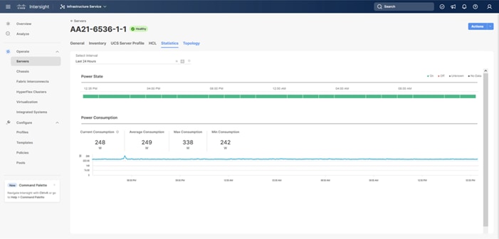
To reduce power consumption, Cisco Intersight provides Server BIOS policies that can be configured to potentially conserve power without affecting performance. These policies provide multiple options specifying both how Cisco UCS X-Series Chassis fans are controlled and how Cisco UCS X-Series Chassis power supplies are used. Additionally these policies provide priority levels for Cisco UCS X-Series servers for power allocation to these servers.
Note: For more information on the BIOS policy options and recommendations, see Performance Tuning Best Practices Guide for Cisco UCS M7 Platforms.
The Cisco UCS Chassis can also implement a policy through Cisco Intersight to provide intelligent options in power use. These options are:
• Power Redundancy: Redundancy Mode determines the number of PSUs the chassis keeps as redundant. N+2 mode is only supported on Cisco UCS X-Series.
• Power Save Mode: If the requested power budget is less than available power capacity, the additional PSUs not required to comply with redundancy policy are placed in Power Save mode.
• Dynamic Power Rebalancing: If enabled, this mode allows the chassis to dynamically reallocate the power between servers depending on their power usage.
• Extended Power Capacity: If enabled, this mode allows chassis available power to be increased by borrowing power from redundant power supplies.
• Power Allocation (Watts): Sets the Allocated Power Budget of the Chassis. This field is only supported for Cisco UCS X-Series Chassis.
VMware vSphere Sustainability
VMware vSphere used in the Adaptive Solutions design also provides several energy management capabilities as outlined below:
• Host Power Management (HPM) – When a host is powered on, this feature can reduce the power consumption of the host. This is enabled using the Power Policy option that can be set to High Performance, Balanced, Low Power, or Custom and interacts with the server BIOS settings. In this CVD, the policy is set to Balanced (default) for a balance between power consumption and performance. Enterprises can change this policy as needed to meet the needs of their workloads and environment. In VMware vSphere 8.0, this policy can be changed by navigating to [vSphere Cluster Name] > Host > Configure > Hardware > Overview.
Figure 69. Power Management configuration with VMware vSphere
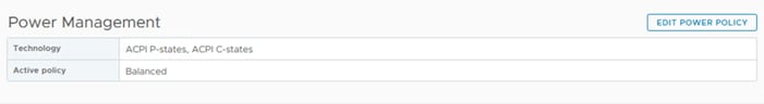
Note: The technology field shows a list of the technologies available to ESXi on that host and is derived from the server BIOS settings. For power savings, both ACPI P-states and ACPI C-states should be available to ESXi.
For more details on the options, see Performance Best Practices for VMware vSphere 8.0.
• Distributed Power Management (DPM) – Unlike HPM, DPM reduces power consumption by powering-off underutilized ESXi hosts in a cluster. DPM will first migrate virtual machines to other hosts in the cluster before putting the hosts into stand-by. When demand increases, DPM will bring the hosts back online and load-balance workloads across all hosts in the cluster. DPM uses Distributed Resource Scheduling (DRS) to migrate VM workloads and is therefore configured along with DRS (at the cluster-level) as shown below from navigating to [vSphere Cluster Name] > Services > vSphere DRS, select EDIT… and find the DPM configuration within the Power Management tab.
Figure 70. Cluster level enablement of Distributed Power Management
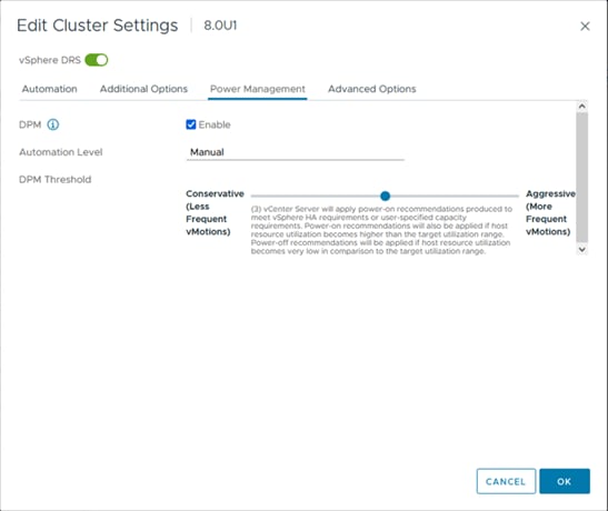
Note: DPM does not violate VMware High Availability (HA) settings and takes it into account to meet the HA requirements.
Note: DPM requires IPMI configuration on the UCS server that was deployed using the IPMI over LAN policy in the UCS Server Profile configuration as discussed earlier. IPMI settings must also be configured on each ESXi host in VMware vCenter by navigating to [vSphere Cluster Name] > Host > Configure > System > Power Management as shown below. In this setup, IPMI over LAN is used to power on a suspended server when demand on the cluster increases.
Figure 71. Distributed Power Management configuration of a specific Cisco UCS X210c server
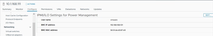
Note: DPM currently does not work with Cisco UCS C-Series servers in Intersight Managed Mode.
• Displaying VMware ESXi Host Power Usage – In addition to IPMI over LAN, local IPMI is also supported in VMware ESXi with Cisco UCS servers. VMware ESXi can use local IPMI to query many server hardware sensors, including server power usage as shown below by navigating to [vSphere Cluster Name] > Host > Monitor > Hardware Health.
Figure 72. VMware vSphere visibility of power use of a specific Cisco UCS X210c server
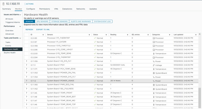
Hitachi Virtual Storage Platform Sustainability
The Hitachi VSP storage solution is certified with CFP (Carbon Footprint of Products) that is a scheme of “visualizing” CO2 equivalent emissions obtained by converting Greenhouse Gas emissions from the entire life cycle stages of a product (goods or service), that is from the raw material acquisition stage to the disposal and recycling stage. Hitachi’s eco-friendly storage products help reduce CO2 emissions by approximately 30 percent to 60 percent compared to previous models.
Figure 73. Carbon Footprint Certification for Hitachi Virtual Storage Platforms
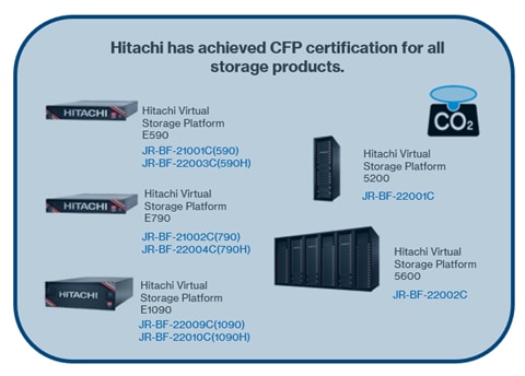
For more information, see: https://ecoleaf-label.jp/pdf_view.php?uuid=4b6e827f-96ad-4743-ba72-051dc2d1bbf5.pdf&filename=JR-BF-22006C_ENG.pdf
Additionally, the Hitachi Virtual Storage Platform brings the following advantages for a greener datacenter:
• Unique hardware-based data compression achieves approximately 60 percent reduction in power consumption
• Fast data compression processing improves read/write performance by 40 percent
• Automatic switching enables high performance and energy savings
• Eliminating the need for data migration saves energy while minimizing waste
The Hitachi Virtual Storage Platform E1090 storage solution is also certified under the USA ENERGY STAR program and is number 1 in its class.
Figure 74. ENERGY STAR Certification
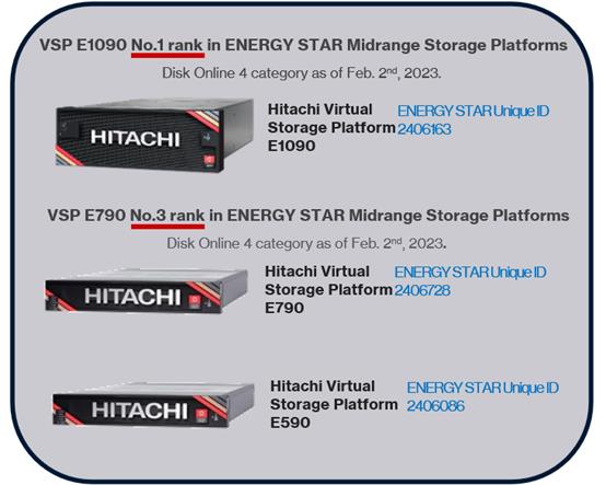
For more information, see: https://www.energystar.gov/productfinder/product/certified-data-center-storage/details/2406163/export/pdf
Some of the key design considerations for the Adaptive Solutions VSI architecture are explained in this section.
Management Design Considerations
Out-of-band Management Network
The management interface of every physical device is connected to a dedicated out-of-band management switch which can be part of the existing management infrastructure in a customer’s environment. The out of band management network provides management access to all the devices in the environment for initial and on-going configuration changes. The routing and switching configuration for this network is independent of the deployment and therefore changes in configurations do not impact management access to the devices. In this CVD, the out-of-band management network is carried within the Cisco Nexus uplinks to allow Cisco UCS CIMC/KVM connectivity.
In-band Management Network
The in-band management is a VLAN configured for connectivity to internally accessed infrastructure in the design. The primary example for in-band connectivity is the management connectivity for VMware vCenter, ESXi and other management components like Hitachi Ops Center. The hardware management interfaces to the Nexus, MDS, UCS, and the Hitachi VSP are in the out-of-band management network which has direct Layer 3 access to the in-band management network. In a production environment might require a firewall separating the two.
VMware vCenter Deployment Consideration
While hosting the VMware vCenter on the same ESXi hosts that the vCenter is managing is supported, it is a best practice to deploy the VMware vCenter on a separate management infrastructure which was the approach in this design. The in-band management VLAN provides connectivity between the VMware vCenter and the ESXi hosts deployed in the environment. In this CVD Deployment Guide, the steps for installing VMware vCenter are not covered, but the configuration is started from what would be considered a fresh install of the VMware vCenter appliance.
Jumbo Frames
An MTU of 9216 is configured at all network levels to allow jumbo frames as needed by the guest OS and application layer. This allows the network at every point to negotiate an MTU up to 9000 with the end point. For VLANs that leave through the Nexus switch uplinks (IB-MGMT and VM-Traffic networks), all endpoints should have an MTU of 1500. For Storage and vMotion VLANs that stay within the design, an MTU of 9000 should be used on all endpoints for higher performance. It is important that all endpoints within a VLAN have the same MTU setting. It is important to remember that most virtual machine network interfaces have an MTU of 1500 set by default and that it may be difficult to change this setting to 9000, especially on many virtual machines. Note that a VLAN tagged trunk can contain both VLANs with MTU 1500 and VLANs with MTU 9000 interfaces.
NTP
For many reasons, including authentication and log correlation, it is critical that all components are properly synchronized to a time-of-day clock. To support this synchronization, all components in this design support network time protocol (NTP). In the setup, the two Cisco Nexus switches are synchronized through NTP to at least two external NTP sources. Cisco Nexus NTP distribution is then set up and all the other components can use the IP of any of the switches’ L3 interfaces, including mgmt0 as an NTP source. If a customer already has NTP distribution in place, that can be used instead of Cisco Nexus switch NTP distribution.
Boot From SAN
When using Cisco UCS Server technology with shared storage, it is a best practice to configure boot from SAN and store the boot partitions on remote storage. This enables architects and administrators to take full advantage of the stateless nature of Cisco UCS Server Profiles for hardware flexibility across the server hardware and overall portability of server identity. Boot from SAN also removes the need to populate local server storage thereby reducing cost and administrative overhead.
UEFI Secure Boot
This validation uses Unified Extensible Firmware Interface (UEFI) Secure Boot. UEFI is a specification that defines a software interface between an operating system and platform firmware. With UEFI secure boot enabled, all executables, such as boot loaders and adapter drivers, are authenticated as properly signed by the BIOS before they can be loaded. Additionally, a Trusted Platform Module (TPM) is also installed in the Cisco UCS compute nodes. VMware ESXi 8.0 U1 supports UEFI Secure Boot and VMware vCenter 8.0 U1 supports UEFI Secure Boot Attestation between the TPM module and ESXi, validating that UEFI Secure Boot has properly taken place.
VMware Virtual Volumes
This validation provides VMware Virtual Volumes (vVols) through the VASA provider within Hitachi Ops Center, for customers looking for more granular control of their SAN environment. A virtual machine can be spread across one vVols datastore or multiple vVols datastores.
NVMe over Fibre Channel
This validation supports NVMe over Fibre Channel (FC-NVMe) to provide the high-performance and low-latency benefits of NVMe across fabrics connecting servers and storage. FC-NVMe is implemented through the Fibre Channel over NVMe (FC-NVMe) standard which is designed to enable NVMe based message commands to transfer data and status information between a host computer and a target storage subsystem over a Fibre Channel network fabric. FC-NVMe simplifies the NVMe command sets into basic FCP instructions.
FC-NVMe requires the creation of additional FC-NVMe specific Fibre Channel interfaces on Cisco UCS Compute nodes and on the Hitachi VSP controllers. Appropriate zoning configurations are also required on Cisco MDS switches.
Deployment Hardware and Software
This chapter contains the following:
• Hardware and Software Revisions
Hardware and Software Revisions
Table 3 lists the hardware and software used in this solution.
Table 3. Hardware and Software Revisions
| Component |
Software |
|
| Network |
Cisco Nexus 93600CD-GX |
10.2(5)M |
| Cisco MDS 9124V |
9.3(2) |
|
| Nexus Dashboard |
2.3(2d) |
|
| Nexus Dashboard Fabric Controller |
12.1.2e |
|
| Compute |
Cisco UCS Fabric Interconnect 6536 and UCS 9108-100G IFM |
4.3(2b) |
| Cisco UCS X210c with Cisco UCS VIC 15231 |
5.1(1.230052) |
|
| Cisco UCS Tools |
1.3.3-1OEM |
|
| Cisco VIC nenic Driver for ESXi |
2.0.11.0 |
|
| Cisco VIC nfnic Driver for ESXi |
5.0.0.41 |
|
| VMware ESXi |
Cisco Custom 8.0 U1a (with 8.0 U1c patch) |
|
| VMware vCenter Appliance |
8.0 U1c |
|
| Cisco Intersight Assist Virtual Appliance |
1.0.9-588 (automatically upgrades to current release) |
|
| Storage |
Hitachi VSP 5600 |
SVOS 90-09-21-00/01 |
| Ops Center Administrator/CM Rest |
10.9.3 |
|
Ramesh Isaac, Technical Marketing Engineer, Cisco Systems, Inc.
Ramesh Isaac is a Technical Marketing Engineer in the Cisco UCS Data Center Solutions Group. Ramesh has worked in the data center and mixed-use lab settings for over 25 years. He started in information technology supporting UNIX environments and focused on designing and implementing multi-tenant virtualization solutions in Cisco labs before entering Technical Marketing where he has supported converged infrastructure and virtual services as part of solution offerings as Cisco. Ramesh has held certifications from Cisco, VMware, and Red Hat.
Sandeep Rakshe, Senior Software Development Engineer, Hitachi Vantara
Sandeep Rakshe is a Senior Software Development Engineer in the Hitachi Engineering Converged UCP group. Sandeep has worked as QA and Solutions group with mainly experience in disaster recovery solutions. He started in information technology with different FC and NAS Storages with expertise in products such as Symantec NetBackup, Veritas Storage foundation, Hitachi Ops Center Protector and Unified compute advisor (Hyperconverged infrastructure solutions), IBM IP flash system IP replication, VMware vSAN. Sandeep has held certifications from Cisco and Red Hat.
Ramakrishna Manupuri, Senior Software Development Engineer, Hitachi Vantara
Ramakrishna Manupuri is a Senior Software Development Engineer, in the Solutions Engineering team of Converged UCP group. He has worked as a Solution engineer with mainly experience in UCP products, Cloud services, SAN Storage solutions and Virtualization technologies with expertise in VMware products such as VMware Cloud Foundation (Hyperconverged infrastructure solution), vCloud Director, vSphere, vSAN, VMware Site Recovery Manager (SRM). Ramakrishna has held certifications from VMware (VCP), AWS Solutions Architect - Associate and Fortinet (NSE4).
Acknowledgements
For their support and contribution to the design, validation, and creation of this Cisco Validated Design, the authors would like to thank:
• John George, Technical Marketing Engineer, Cisco Systems, Inc.
• Archana Sharma, Engineering Technical Leader, Cisco Systems, Inc.
• Arvin Jami, Solutions Architect, Hitachi Vantara
This appendix contains the following:
• Compute
• Network
• Storage
Cisco Intersight: https://www.intersight.com
Cisco Intersight Managed Mode: https://www.cisco.com/c/en/us/td/docs/unified_computing/Intersight/b_Intersight_Managed_Mode_Configuration_Guide.html
Cisco Unified Computing System: https://www.cisco.com/site/us/en/products/computing/servers-unified-computing-systems/index.html
Cisco UCS 6536 Fabric Interconnects: https://www.cisco.com/c/en/us/products/collateral/servers-unified-computing/ucs6536-fabric-interconnect-ds.html
Cisco Nexus 9000 Series Switches: http://www.cisco.com/c/en/us/products/switches/nexus-9000-series-switches/index.html
Cisco MDS 9124V Switches: https://www.cisco.com/c/en/us/products/collateral/storage-networking/mds-9100-series-multilayer-fabric-switches/mds-9124v-fibre-channel-switch-ds.html
Cisco Nexus Dashboard Fabric Controller: https://www.cisco.com/c/en/us/products/collateral/cloud-systems-management/prime-data-center-network-manager/nb-06-ndfc-ds-cte-en.html
Hitachi Virtual Storage Platform E series: https://www.hitachivantara.com/en-us/products/storage-platforms/primary-block-storage/vsp-e-series.html
Hitachi Virtual Storage Platform 5000 series: https://www.hitachivantara.com/en-us/products/storage-platforms/primary-block-storage/vsp-5000-series.html
Hitachi SVOS: https://www.hitachivantara.com/en-us/products/storage-platforms/primary-block-storage/virtualization-operating-system.html
Hitachi Ops Center: https://www.hitachivantara.com/en-us/products/storage-software/ai-operations-management/ops-center.html
VMware vCenter Server: http://www.vmware.com/products/vcenter-server/overview.html
VMware vSphere: https://www.vmware.com/products/vsphere
Cisco UCS Hardware Compatibility Matrix: https://ucshcltool.cloudapps.cisco.com/public/
VMware and Cisco Unified Computing System: http://www.vmware.com/resources/compatibility
Hitachi Product Compatibility Guide: https://compatibility.hitachivantara.com/
For comments and suggestions about this guide and related guides, join the discussion in the Cisco Community at https://cs.co/en-cvds.
CVD Program
ALL DESIGNS, SPECIFICATIONS, STATEMENTS, INFORMATION, AND RECOMMENDATIONS (COLLECTIVELY, "DESIGNS") IN THIS MANUAL ARE PRESENTED "AS IS," WITH ALL FAULTS. CISCO AND ITS SUPPLIERS DISCLAIM ALL WARRANTIES, INCLUDING, WITHOUT LIMITATION, THE WARRANTY OF MERCHANTABILITY, FITNESS FOR A PARTICULAR PURPOSE AND NONINFRINGEMENT OR ARISING FROM A COURSE OF DEALING, USAGE, OR TRADE PRACTICE. IN NO EVENT SHALL CISCO OR ITS SUPPLIERS BE LIABLE FOR ANY INDIRECT, SPECIAL, CONSEQUENTIAL, OR INCIDENTAL DAMAGES, INCLUDING, WITHOUT LIMITATION, LOST PROFITS OR LOSS OR DAMAGE TO DATA ARISING OUT OF THE USE OR INABILITY TO USE THE DESIGNS, EVEN IF CISCO OR ITS SUPPLIERS HAVE BEEN ADVISED OF THE POSSIBILITY OF SUCH DAMAGES.
THE DESIGNS ARE SUBJECT TO CHANGE WITHOUT NOTICE. USERS ARE SOLELY RESPONSIBLE FOR THEIR APPLICATION OF THE DESIGNS. THE DESIGNS DO NOT CONSTITUTE THE TECHNICAL OR OTHER PROFESSIONAL ADVICE OF CISCO, ITS SUPPLIERS OR PARTNERS. USERS SHOULD CONSULT THEIR OWN TECHNICAL ADVISORS BEFORE IMPLEMENTING THE DESIGNS. RESULTS MAY VARY DEPENDING ON FACTORS NOT TESTED BY CISCO.
CCDE, CCENT, Cisco Eos, Cisco Lumin, Cisco Nexus, Cisco StadiumVision, Cisco TelePresence, Cisco WebEx, the Cisco logo, DCE, and Welcome to the Human Network are trademarks; Changing the Way We Work, Live, Play, and Learn and Cisco Store are service marks; and Access Registrar, Aironet, AsyncOS, Bringing the Meeting To You, Catalyst, CCDA, CCDP, CCIE, CCIP, CCNA, CCNP, CCSP, CCVP, Cisco, the Cisco Certified Internetwork Expert logo, Cisco IOS, Cisco Press, Cisco Systems, Cisco Systems Capital, the Cisco Systems logo, Cisco Unified Computing System (Cisco UCS), Cisco UCS B-Series Blade Servers, Cisco UCS C-Series Rack Servers, Cisco UCS S-Series Storage Servers, Cisco UCS X-Series, Cisco UCS Manager, Cisco UCS Management Software, Cisco Unified Fabric, Cisco Application Centric Infrastructure, Cisco Nexus 9000 Series, Cisco Nexus 7000 Series. Cisco Prime Data Center Network Manager, Cisco NX-OS Software, Cisco MDS Series, Cisco Unity, Collaboration Without Limitation, EtherFast, EtherSwitch, Event Center, Fast Step, Follow Me Browsing, FormShare, GigaDrive, HomeLink, Internet Quotient, IOS, iPhone, iQuick Study, LightStream, Linksys, MediaTone, MeetingPlace, MeetingPlace Chime Sound, MGX, Networkers, Networking Academy, Network Registrar, PCNow, PIX, PowerPanels, ProConnect, ScriptShare, SenderBase, SMARTnet, Spectrum Expert, StackWise, The Fastest Way to Increase Your Internet Quotient, TransPath, WebEx, and the WebEx logo are registered trade-marks of Cisco Systems, Inc. and/or its affiliates in the United States and certain other countries. (LDW_P4)
All other trademarks mentioned in this document or website are the property of their respective owners. The use of the word partner does not imply a partnership relationship between Cisco and any other company. (0809R)