FlexPod Datacenter using IaC with Cisco IMM M7, VMware vSphere 8, and NetApp ONTAP 9.12.1
Available Languages
Bias-Free Language
The documentation set for this product strives to use bias-free language. For the purposes of this documentation set, bias-free is defined as language that does not imply discrimination based on age, disability, gender, racial identity, ethnic identity, sexual orientation, socioeconomic status, and intersectionality. Exceptions may be present in the documentation due to language that is hardcoded in the user interfaces of the product software, language used based on RFP documentation, or language that is used by a referenced third-party product. Learn more about how Cisco is using Inclusive Language.
- US/Canada 800-553-2447
- Worldwide Support Phone Numbers
- All Tools
 Feedback
 Feedback
![]()
In partnership with:

About the Cisco Validated Design Program
The Cisco Validated Design (CVD) program consists of systems and solutions designed, tested, and documented to facilitate faster, more reliable, and more predictable customer deployments. For more information, go to: http://www.cisco.com/go/designzone.
The FlexPod Datacenter solution is a validated design for deploying Cisco and NetApp technologies and products to build shared private and public cloud infrastructure. Cisco and NetApp have partnered to deliver a series of FlexPod solutions that enable strategic data center platforms. The success of the FlexPod solution is driven through its ability to evolve and incorporate both technology and product innovations in the areas of management, compute, storage, and networking. This document explains the deployment details of incorporating the Cisco UCS X-Series M7 and C-Series M7 servers into the FlexPod Datacenter and the ability to monitor and manage FlexPod components from the cloud using Cisco Intersight. Some of the key advantages of integrating Cisco UCS M7 servers into the FlexPod infrastructure are:
● Upgraded servers: 4th Gen Intel Xeon Scalable Processors with up to 60 cores per processor and up 8TB of DDR-4800 DIMMs.
● Sustainability: taking advantage of sustainability and power usage monitoring features of all the components of the stack and utilizing the Cisco UCS X-Series advanced power and cooling policies.
● Simpler and programmable infrastructure: infrastructure as code delivered using Ansible.
● End-to-End 100Gbps Ethernet: utilizing the 5th Generation Cisco UCS VICs 15231 and 15238, the 5th Generation Cisco UCS 6536 Fabric Interconnect, and the Cisco UCSX-I-9108-100G Intelligent Fabric Module to deliver 100Gbps Ethernet from the server through the network to the storage.
● End-to-End 32Gbps Fibre Channel: utilizing the 5th Generation Cisco UCS VICs 15231 and 15238, the 5th Generation Cisco UCS 6536 Fabric Interconnect, and the Cisco UCSX-I-9108-100G Intelligent Fabric Module to deliver 32Gbps Ethernet from the server (via 100Gbps FCoE) through the network to the storage.
● Built for investment protections: design ready for future technologies such as liquid cooling and high-Wattage CPUs; CXL-ready.
In addition to the compute-specific hardware and software innovations, the integration of the Cisco Intersight cloud platform with VMware vCenter, NetApp Active IQ Unified Manager, and Cisco Nexus and MDS switches delivers monitoring, orchestration, and workload optimization capabilities for different layers (virtualization, storage, and networking) of the FlexPod infrastructure. The modular nature of the Cisco Intersight platform also provides an easy upgrade path to additional services, such as workload optimization.
For information about the FlexPod design and deployment details, including the configuration of various elements of design and associated best practices, refer to Cisco Validated Designs for FlexPod, here: https://www.cisco.com/c/en/us/solutions/design-zone/data-center-design-guides/flexpod-design-guides.html.
Solution Overview
This chapter contains the following:
● Audience
Powered by the Cisco Intersight cloud-operations platform, the Cisco UCS with X-Series and Cisco UCS C-Series enables the next-generation cloud-operated FlexPod infrastructure that not only simplifies data-center management but also allows the infra-structure to adapt to the unpredictable needs of modern applications as well as traditional workloads. With the Cisco Intersight platform, you get all the benefits of SaaS delivery and the full lifecycle management of Intersight-connected distributed servers and integrated NetApp storage systems across data centers, remote sites, branch offices, and edge environments.
The intended audience of this document includes but is not limited to IT architects, sales engineers, field consultants, professional services, IT managers, partner engineering, and customers who want to take advantage of an infrastructure built to deliver IT efficiency and enable IT innovation.
What’s New in this Release?
The following design elements distinguish this version of FlexPod from previous models:
● Cisco UCS X210C M7, C220 M7, and C240 M7 servers with Intel Xeon Scalable Processors with up to 60 cores per processor, up to 8TB of DDR-4800 DIMMs, and Cisco 5th Generation Virtual Interface Cards (VICs)
● An updated, more complete end-to-end Infrastructure as Code (IaC) Day 0 configuration of the FlexPod Infrastructure utilizing Ansible Scripts
● NetApp ONTAP 9.12.1
● VMware vSphere 8.0
Deployment Hardware and Software
This chapter contains the following:
● Ansible Automation Workflow and Solution Deployment
The FlexPod Datacenter with Cisco UCS and Cisco Intersight meets the following general design requirements:
● Resilient design across all layers of the infrastructure with no single point of failure
● Scalable design with the flexibility to add compute capacity, storage, or network bandwidth as needed
● Modular design that can be replicated to expand and grow as the needs of the business grow
● Flexible design that can support different models of various components with ease
● Simplified design with ability to integrate and automate with external automation tools
● Cloud-enabled design which can be configured, managed, and orchestrated from the cloud using GUI or APIs
To deliver a solution which meets all these design requirements, various solution components are connected and configured as covered in the upcoming sections.
The FlexPod Datacenter solution with Cisco UCS IMM M7, VMware 8.0, and NetApp ONTAP 9.12.1 is built using the following hardware components:
● Cisco UCS X9508 Chassis with Cisco UCSX-I-9108-100G intelligent fabric modules (IFMs) and up to eight Cisco UCS X210C M7 Compute Nodes with 4th Generation Intel Xeon Scalable CPUs
● Fifth-generation Cisco UCS 6536 Fabric Interconnects to support 100GbE, 25GbE, and 32GFC connectivity from various components
● Cisco UCS C220 M7 and C240 M7 rack mount servers with 4th Generation Intel Xeon Scalable CPUs
● High-speed Cisco NX-OS-based Nexus 93600CD-GX switching design to support 100GE and 400GE connectivity
● NetApp AFF A800 end-to-end NVMe storage with 25G or 100G Ethernet and (optional) 32G Fibre Channel connectivity
● Cisco MDS 9132T* switches to support Fibre Channel storage configuration
Note: * Cisco MDS 9132T and FC connectivity is not needed when implementing IP-based connectivity design supporting iSCSI boot from SAN, NFS, and NVMe-TCP.
The software components of this solution consist of:
● Cisco Intersight to deploy, maintain, and support the Cisco UCS server components
● Cisco Intersight SaaS platform to maintain and support the FlexPod components
● Cisco Intersight Assist Virtual Appliance to help connect NetApp ONTAP, VMware vCenter, and Cisco Nexus and MDS switches with Cisco Intersight
● NetApp Active IQ Unified Manager to monitor and manage the storage and for NetApp ONTAP integration with Cisco Intersight
● VMware vCenter to set up and manage the virtual infrastructure as well as Cisco Intersight integration
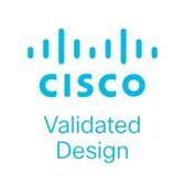
FlexPod Datacenter for IP-based Storage Access
Figure 1 shows various hardware components and the network connections for the IP-based FlexPod design.
The reference hardware configuration includes:
● Two Cisco Nexus 93600CD-GX Switches in Cisco NX-OS mode provide the switching fabric.
● Two Cisco UCS 6536 Fabric Interconnects (FI) provide the chassis connectivity. Two 100 Gigabit Ethernet ports from each FI, configured as a Port-Channel, are connected to each Nexus 93600CD-GX.
● One Cisco UCS X9508 Chassis connects to fabric interconnects using Cisco UCS UCSX-I-9108-100G IFMs, where four 100 Gigabit Ethernet ports are used on each IOM to connect to the appropriate FI. If additional bandwidth is required, all eight 100G ports can be utilized.
● One NetApp AFF A800 HA pair connects to the Cisco Nexus 93600CD-GX Switches using two 100 GE ports from each controller configured as a Port-Channel.
● One Cisco UCS C240 M7 rack mount server connects to the Fabric Interconnects using two 100 GE ports per server.
● One Cisco UCS C220 M7 rack mount server connects to the Fabric Interconnects using four 25 GE ports per server via breakout.
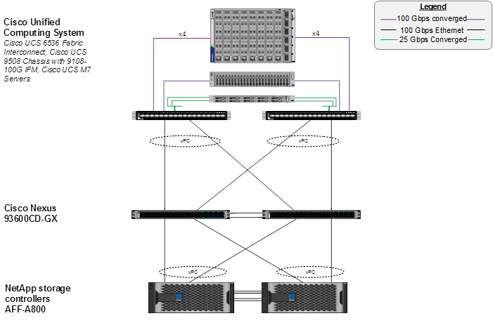
FlexPod Datacenter for FC-based Storage Access
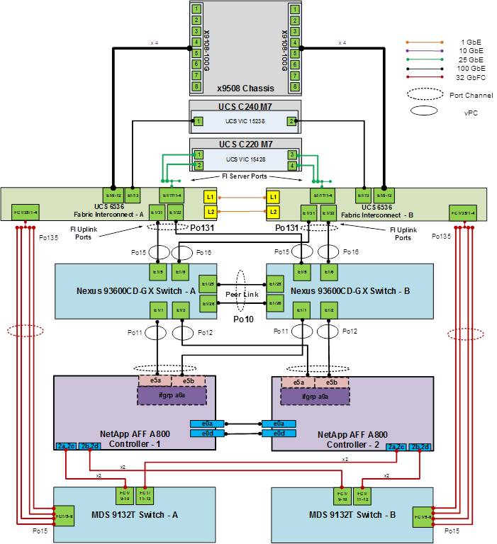
Figure 2 shows various hardware components and the network connections for the FC-based FlexPod design.
The reference hardware configuration includes:
● Two Cisco Nexus 93600CD-GX Switches in Cisco NX-OS mode provide the switching fabric.
● Two Cisco UCS 6536 Fabric Interconnects (FI) provide the chassis connectivity. Two 100 Gigabit Ethernet ports from each FI, configured as a Port-Channel, are connected to each Cisco Nexus 93600CD-GX. Four FC ports are connected to the Cisco MDS 9132T switches using 32-Gbps Fibre Channel connections via breakout configured as a single port channel for SAN connectivity.
● One NetApp AFF A800 HA pair connects to the Cisco Nexus 93600CD-GX Switches using two 100 GE ports from each controller configured as a Port-Channel. Two 32Gbps FC ports from each controller are connected to each Cisco MDS 9132T for SAN connectivity.
● One Cisco UCS C240 M7 Rack Mount Server connects to the Fabric Interconnects using two 100 GE ports per server. These connections are also converged and carry both Ethernet and FCoE.
● One Cisco UCS C220 M7 Rack Mount Server connects to the Fabric Interconnects using four 25 GE ports per server. These connections are also converged and carry both Ethernet and FCoE.
Note: The NetApp storage controller and disk shelves should be connected according to best practices for the specific storage controller and disk shelves. For disk shelf cabling, refer to NetApp Support: https://docs.netapp.com/us-en/ontap-systems/index.html
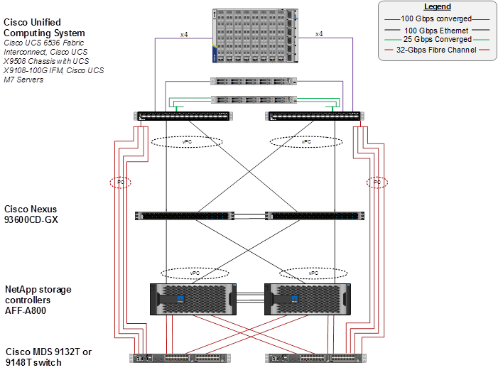
FlexPod Datacenter for FC-based Storage Access with Nexus SAN Switching
Figure 3 shows various hardware components and the network connections for the FC-based FlexPod design.
The reference hardware configuration includes:
● Two Cisco Nexus 93180YC-FX, 93360YC-FX2, or 9336C-FX2-E Switches in Cisco NX-OS mode provide the switching fabric for both LAN and SAN.
● Two Cisco UCS 6536 Fabric Interconnects (FI) provide the chassis connectivity. Two 100 Gigabit Ethernet ports from each FI, configured as a Port-Channel, are connected to each Nexus switch. Two 100G FCoE ports are connected to the Cisco Nexus switches configured as a single Ethernet port channel for SAN connectivity.
● One Cisco UCS X9508 Chassis connects to fabric interconnects using Cisco UCS UCSX-I-9108-100G IFMs, where four 100 Gigabit Ethernet ports are used on each IOM to connect to the appropriate FI. If additional bandwidth is required, all eight 100G ports can be utilized. The chassis to fabric interconnect connections are converged and carry both Ethernet and Fibre Channel over Ethernet (FCoE).
● One NetApp AFF A800 HA pair connects to the Cisco Nexus Switches using two 100 GE ports from each controller configured as a Port-Channel. Two 32Gbps FC ports from each controller are connected to each Cisco Nexus switch for SAN connectivity (Cisco Nexus 9336C-FX2-E using breakout).
● One Cisco UCS C220 M7 Rack Mount Server connects to the Fabric Interconnects using two 100 GE ports per server. These connections are also converged and carry both Ethernet and FCoE.
● One Cisco UCS C220 M7 Rack Mount Server connects to the Fabric Interconnects four 25 GE ports per server. These connections are also converged and carry both Ethernet and FCoE.
Note: The NetApp storage controller and disk shelves should be connected according to best practices for the specific storage controller and disk shelves. For disk shelf cabling, refer to NetApp Support: https://docs.netapp.com/us-en/ontap-systems/index.html
VLAN Configuration
Table 1 lists VLANs configured for setting up the FlexPod environment along with their usage.
| VLAN ID |
Name |
Usage |
IP Subnet used in this deployment |
| 2 |
Native-VLAN |
Use VLAN 2 as native VLAN instead of default VLAN (1). |
|
| 1020 |
OOB-MGMT-VLAN |
Out-of-band management VLAN to connect management ports for various devices |
10.102.0.0/24; GW: 10.102.0.254 |
| 1021 |
IB-MGMT-VLAN |
In-band management VLAN utilized for all in-band management connectivity - for example, ESXi hosts, VM management, and so on. |
10.102.1.0/24; GW: 10.102.1.254 |
| 1022 |
VM-Traffic |
VM data traffic VLAN |
10.102.2.0/24; GW: 10.102.2.254 |
| 3050 |
NFS-VLAN |
NFS VLAN for mounting datastores in ESXi servers for VMs |
192.168.50.0/24 ** |
| 3010* |
iSCSI-A |
iSCSI-A path for storage traffic including boot-from-san traffic |
192.168.10.0/24 ** |
| 3020* |
iSCSI-B |
iSCSI-B path for storage traffic including boot-from-san traffic |
192.168.20.0/24 ** |
| 3030 |
NVMe-TCP-A |
NVMe-TCP-A path when using NVMe-TCP |
192.168.30.0/24 ** |
| 3040 |
NVMe-TCP-B |
NVMe-TCP-B path when using NVMe-TCP |
192.168.40.0/24 ** |
| 3000 |
vMotion |
VMware vMotion traffic |
192.168.0.0/24 ** |
* iSCSI VLANs are not required if using FC storage access.
** IP gateway is not needed since no routing is required for these subnets
It is assumed that if you are using FC boot, that you would also use NFS and optionally FC-NVMe, but not iSCSI or NVMe-TCP. On the other hand, it is also assumed that if you are using iSCSI boot, that you would also use NFS and optionally NVMe-TCP, but not FC or FC-NVMe.
Some of the key highlights of VLAN usage are as follows:
● VLAN 1020 allows you to manage and access out-of-band management interfaces of various devices.
● VLAN 1021 is used for in-band management of VMs, ESXi hosts, and other infrastructure services.
● VLAN 3050 provides ESXi hosts access to the NFS datastores hosted on the NetApp Controllers for deploying VMs.
● A pair of iSCSI VLANs (3010 and 3020) is configured to provide access to boot LUNs for ESXi hosts. These VLANs are not needed if you are using FC-only connectivity.
● A pair of NVMe-TCP VLANs (3030 and 3040) are configured to provide access to NVMe datastores when NVMe-TCP is being used.
● VLAN 3000 is used for VM vMotion.
Table 2 lists the infrastructure VMs necessary for deployment as outlined in this document.
| Virtual Machine Description |
VLAN |
IP Address |
Comments |
| vCenter Server |
1021 |
10.102.1.100 |
Hosted on either pre-existing management infrastructure (preferred) or on FlexPod |
| NetApp ONTAP Tools for VMware vSphere |
1021 |
10.102.1.99 |
Hosted on FlexPod |
| NetApp SnapCenter Plug-in for VMware vSphere |
1021 |
10.102.1.98 |
Hosted on either pre-existing management infrastructure (preferred) or on FlexPod |
| NetApp Active IQ Unified Manager |
1021 |
10.102.1.97 |
Hosted on FlexPod |
| Cisco Intersight Assist |
1021 |
10.102.1.96 |
Hosted on FlexPod |
| Nexus Dashboard Fabric Controller (NDFC)-SAN |
1021 and 1020 |
10.102.1.21 |
Hosted on a server that is under the FlexPod Datacenter, but not part of a cluster. Consider deploying an extra server for this in the FlexPod Management Cluster and moving this server out to the Datacenter level in vCenter. |
Table 3 lists the software revisions for various components of the solution.
| Layer |
Device |
Image Bundle |
Comments |
| Compute |
Cisco UCS |
4.2(3d) |
Cisco UCS GA release for infrastructure including FIs and IOM/IFM. |
|
|
Cisco UCS X210C M7 |
5.1(1.230052) |
|
|
|
Cisco UCS C220/240 M7 |
4.3(1.230138) |
|
| Network |
Cisco Nexus 93600CD-GX NX-OS |
10.2(5)M |
|
| Cisco MDS 9132T |
9.3(2) |
Requires SMART Licensing |
|
| Storage |
NetApp AFF A800/A400 |
ONTAP 9.12.1* |
Latest patch release |
| Software |
Cisco Intersight Assist Appliance |
1.0.9-558 |
1.0.9-538 initially installed and then automatically upgraded |
| VMware vCenter |
8.0 |
Latest 8.0 Build |
|
| VMware ESXi |
8.0 |
Latest 8.0 Build |
|
| VMware ESXi nfnic FC Driver |
5.0.0.37 |
Supports FC-NVMe |
|
| VMware ESXi nenic Ethernet Driver |
1.0.45.0 |
|
|
| NetApp ONTAP Tools for VMware vSphere |
9.12 |
Formerly Virtual Storage Console (VSC) |
|
| NetApp SnapCenter Plug-in for VMware vSphere |
4.8 |
|
|
| NetApp Active IQ Unified Manager |
9.12 |
|
Note: NetApp ONTAP 9.13.1 was also tested with the ONTAP Ansible scripts in the Github repository for this project.
FlexPod Cabling
The information in this section is provided as a reference for cabling the physical equipment in a FlexPod environment. To simplify cabling requirements, a cabling diagram was used.
The cabling diagram in this section contains the details for the prescribed and supported configuration of the NetApp AFF 400 running NetApp ONTAP 9.12.1.
Note: For any modifications of this prescribed architecture, consult the NetApp Interoperability Matrix Tool (IMT).
Note: This document assumes that out-of-band management ports are plugged into an existing management infrastructure at the deployment site. These interfaces will be used in various configuration steps.
Note: Be sure to use the cabling directions in this section as a guide.
The NetApp storage controller and disk shelves should be connected according to best practices for the specific storage controller and disk shelves. For disk shelf cabling, refer to NetApp Support.
Figure 4 details the cable connections used in the validation lab for the FlexPod topology based on the Cisco UCS 6536 fabric interconnect. Four 32Gb uplinks connect as port-channels from each Cisco UCS Fabric Interconnect to the MDS switches, and a total of eight 32Gb links connect the MDS switches to the NetApp AFF controllers. Also, two 100Gb links connect each Cisco UCS Fabric Interconnect to the Cisco Nexus Switches and each NetApp AFF controller to the Cisco Nexus Switches. Additional 1Gb management connections will be needed for an out-of-band network switch that sits apart from the FlexPod infrastructure. Each Cisco UCS fabric interconnect and Cisco Nexus switch is connected to the out-of-band network switch, and each AFF controller has a connection to the out-of-band network switch. Layer 3 network connectivity is required between the Out-of-Band (OOB) and In-Band (IB) Management Subnets. This cabling diagram includes both the FC-boot and iSCSI-boot configurations.
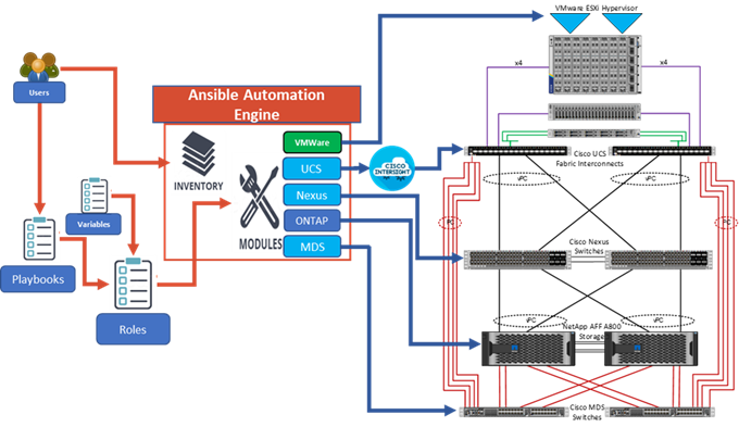
Ansible Automation Workflow and Solution Deployment
The Ansible automated FlexPod solution uses a management workstation (control machine) to run Ansible playbooks to configure Cisco Nexus, NetApp ONTAP Storage, Cisco UCS, Cisco MDS, and VMware ESXi.
Figure 5 illustrates the FlexPod solution implementation workflow which is explained in the following sections. The FlexPod infrastructure layers are first configured in the order illustrated.
Prerequisites
Setting up the solution begins with a management workstation or VM that has access to the Internet and with a working installation of Ansible. The management workstation commonly runs a variant of Linux or MacOS for ease of use with these command-line-based tools. Instructions for installing the workstation are not included in this document, but basic installation and configuration of Ansible is explained. A guide for getting started with Ansible can be found here: https://docs.ansible.com/ansible_community.html
● To use the Ansible playbooks demonstrated in this document, the management workstation must also have a working installation of Git and access to the Cisco DevNet public GitHub repository. The Ansible playbooks used in this document are cloned from the public repositories, located at the following links:
◦ Cisco DevNet: https://developer.cisco.com/codeexchange/github/repo/ucs-compute-solutions/FlexPod-IMM-VMware
◦ GitHub repository: https://github.com/ucs-compute-solutions/FlexPod-IMM-VMwarehttps://github.com/ucs-compute-solutions/FlexPod-IMM-VMware
● The Cisco Nexus and MDS Switches, NetApp Storage, and Cisco UCS must be physically racked, cabled, powered, and configured with management IP addresses before the Ansible-based installation procedure can begin as shown in the cabling diagram (Figure 4). If necessary, upgrade the Cisco Nexus Switches to release 10.2(5)M, and the Cisco MDS Switches to release 9.3(2).
● Before running each Ansible Playbook to setup the Network, Storage, Cisco UCS, and VMware ESXi various variables must be updated based on the customers environment and specific implementation with values such as the VLANs, pools and ports on Cisco UCS, IP addresses for NFS, iSCSI, and NVMe-TCP interfaces and values needed for VMware ESXi.
● Day 2 Configuration tasks such as adding datastores or ESXi servers can be performed manually or with Cisco Intersight Cloud Orchestrator (ICO).
Procedure 1. Prepare Management Workstation (Control Machine)
In this procedure, the installation steps are performed on either RHEL 8.8 or Rocky Linux 8.8 (install default Server with GUI) management host to prepare the host for solution deployment to support the automation of Cisco UCS, Cisco Nexus, NetApp Storage, Cisco MDS, and VMware ESXi using Ansible Playbooks.
Note: The following steps were performed on both RHEL 8.8 and Rocky Linux 8.8 Virtual Machines as the admin user.
Step 1. Install Python 3.11.
sudo dnf install python3.11
Step 2. Install pip3.11.
curl https://bootstrap.pypa.io/get-pip.py -o get-pip.py
python3.11 get-pip.py
rm get-pip.py
Step 3. Install Ansible engine with Python 3.11.
python3.11 -m pip install --user ansible
Step 4. Configure Ansible to use python3.11.
echo [defaults] > ~/.ansible.cfg
echo interpreter_python=/usr/bin/python3.11 >> ~/.ansible.cfg
Step 5. Verify Ansible version to make sure it is release 2.9 or later.
ansible --version
ansible [core 2.15.2]
config file = /home/admin/.ansible.cfg
configured module search path = ['/home/admin/.ansible/plugins/modules', '/usr/share/ansible/plugins/modules']
ansible python module location = /home/admin/.local/lib/python3.11/site-packages/ansible
ansible collection location = /home/admin/.ansible/collections:/usr/share/ansible/collections
executable location = /home/admin/.local/bin/ansible
python version = 3.11.2 (main, Jun 6 2023, 07:39:01) [GCC 8.5.0 20210514 (Red Hat 8.5.0-18)] (/usr/bin/python3.11)
jinja version = 3.1.2
libyaml = True
Step 6. Install sshpass.
sudo dnf install sshpass
Step 7. Install git.
sudo dnf install git
Step 8. Install NetApp specific python modules.
pip3.11 install netapp-lib
Step 9. Install UCSM SDK.
pip3.11 install ucsmsdk
Note: This step and the collection installation below was put in just in case this Ansible machine will also be used with Cisco UCS Manager installations.
Step 10. Install ansible-galaxy collections and other dependencies for Cisco Nexus (and MDS), NetApp ONTAP, Cisco UCS, VMware, and NetApp management tools as follows:
ansible-galaxy collection install cisco.ucs –force
ansible-galaxy collection install cisco.intersight --force
ansible-galaxy collection install cisco.nxos --force
pip3.11 install ansible-pylibssh
ansible-galaxy collection install netapp.ontap --force
ansible-galaxy collection install community.vmware --force
pip3.11 install -r ~/.ansible/collections/ansible_collections/community/vmware/requirements.txt
pip3.11 install aiohttp
pip3.11 install pexpect
pip3.11 install jmespath
Note: The cisco.nxos collection is used for both Cisco Nexus and Cisco MDS configuration.
Procedure 2. Clone GitHub Collection
Note: You need to use a GitHub repository from one public location; the first step in the process is to clone the GitHub collection named FlexPod-IMM-VMware (https://github.com/ucs-compute-solutions/FlexPod-IMM-VMware.git) to a new empty folder on the management workstation. Cloning the repository creates a local copy, which is then used to run the playbooks that have been created for this solution.
Step 1. From the management workstation, create a new folder for the project. The GitHub collection will be cloned in a new folder inside this one, named /home/admin/FlexPod-IMM-VMware.
Step 2. Open a command-line or console interface on the management workstation and change directories to the new folder just created.
Step 3. Clone the GitHub collection using the following command:
git clone https://github.com/ucs-compute-solutions/FlexPod-IMM-VMware.git
Step 4. Change directories to the new folder named FlexPod-IMM-VMware.
Network Switch Configuration
This chapter contains the following:
● Ansible Nexus Switch Configuration
This chapter provides a detailed procedure for configuring the Cisco Nexus 93360YC-FX2 switches for use in a FlexPod environment. The Cisco Nexus 93360YC-FX2 will be used for LAN switching in this solution.
Note: The following procedures describe how to configure the Cisco Nexus switches for use in a base FlexPod environment. This procedure assumes the use of Cisco Nexus 9000 10.2(5)M.
● If using the Cisco Nexus 93360YC-FX2 switches or other Cisco Nexus switches for both LAN and SAN switching, please refer to section FlexPod with Cisco Nexus 93360YC-FX2 SAN Switching Configuration in the Appendix.
● The following procedure includes the setup of NTP distribution on both the mgmt0 port and the in-band management VLAN. The interface-vlan feature and ntp commands are used to set this up. This procedure also assumes that the default VRF is used to route the in-band management VLAN.
● This procedure sets up and uplink virtual port channel (vPC) with the IB-MGMT and OOB-MGMT VLANs allowed.
● This validation assumes that both switches have been reset to factory defaults by using the “write erase” command followed by the “reload” command.
Follow the physical connectivity guidelines for FlexPod as explained in section FlexPod Cabling.
The following procedures describe this basic configuration of the Cisco Nexus switches for use in the FlexPod environment. This procedure assumes the use of Cisco Nexus 9000 10.2(5)M, the Cisco suggested Nexus switch release at the time of this validation.
Procedure 1. Set Up Initial Configuration from a serial console
Set up the initial configuration for the Cisco Nexus A switch on <nexus-A-hostname>.
Step 1. Configure the switch.
Note: On initial boot, the NX-OS setup automatically starts and attempts to enter Power on Auto Provisioning.
Abort Power On Auto Provisioning [yes - continue with normal setup, skip - bypass password and basic configuration, no - continue with Power On Auto Provisioning] (yes/skip/no)[no]: yes
Disabling POAP.......Disabling POAP
poap: Rolling back, please wait... (This may take 5-15 minutes)
---- System Admin Account Setup ----
Do you want to enforce secure password standard (yes/no) [y]: Enter
Enter the password for "admin": <password>
Confirm the password for "admin": <password>
Would you like to enter the basic configuration dialog (yes/no): yes
Create another login account (yes/no) [n]: Enter
Configure read-only SNMP community string (yes/no) [n]: Enter
Configure read-write SNMP community string (yes/no) [n]: Enter
Enter the switch name: <nexus-A-hostname>
Continue with Out-of-band (mgmt0) management configuration? (yes/no) [y]: Enter
Mgmt0 IPv4 address: <nexus-A-out_of_band_mgmt0-ip>
Mgmt0 IPv4 netmask: <nexus-A-mgmt0-netmask>
Configure the default gateway? (yes/no) [y]: Enter
IPv4 address of the default gateway: <nexus-A-mgmt0-gw>
Configure advanced IP options? (yes/no) [n]: Enter
Enable the telnet service? (yes/no) [n]: Enter
Enable the ssh service? (yes/no) [y]: Enter
Type of ssh key you would like to generate (dsa/rsa) [rsa]: Enter
Number of rsa key bits <1024-2048> [1024]: Enter
Configure the ntp server? (yes/no) [n]: Enter
Configure default interface layer (L3/L2) [L2]: Enter
Configure default switchport interface state (shut/noshut) [noshut]: shut
Enter basic FC configurations (yes/no) [n]: n
Configure CoPP system profile (strict/moderate/lenient/dense) [strict]: Enter
Would you like to edit the configuration? (yes/no) [n]: Enter
Step 2. Review the configuration summary before enabling the configuration.
Use this configuration and save it? (yes/no) [y]: Enter
Step 3. To set up the initial configuration of the Cisco Nexus B switch, repeat steps 1 and 2 with the appropriate host and IP address information.
Ansible Nexus Switch Configuration
Procedure 1. Configure the Cisco Nexus switches from the management workstation
Step 1. Add Nexus switch ssh keys to /home/admin/.ssh/known_hosts. Adjust known_hosts as necessary if errors occur.
ssh admin@<nexus-A-mgmt0-ip>
exit
ssh admin@<nexus-B-mgmt0-ip>
exit
Step 2. Edit the following variable files to ensure proper Cisco Nexus variables are entered:
● FlexPod-IMM-VMware/FlexPod-IMM-VMware/group_vars/secrets.yml
● FlexPod-IMM-VMware/FlexPod-IMM-VMware/inventory
● FlexPod-IMM-VMware/FlexPod-IMM-VMware/group_vars/all.yml
● FlexPod-IMM-VMware/FlexPod-IMM-VMware/host_vars/n9kA.yml
● FlexPod-IMM-VMware/FlexPod-IMM-VMware/host_vars/n9kB.yml
● FlexPod-IMM-VMware/FlexPod-IMM-VMware/roles/NEXUSconfig/defaults/main.yml
Note: Switch configuration can be done one switch at a time by commenting one switch out in inventory and running the playbook. This may need to be done if the switches are shared with other FlexPods and additional configuration needs to be added between playbook runs.
Step 3. From FlexPod-IMM-VMware/FlexPod-IMM-VMware, run the Setup_Nexus.yml Ansible playbook.
ansible-playbook ./Setup_Nexus.yml -i inventory
Step 4. When the Ansible playbook has been run on both switches, it is important to configure the local time so that logging time alignment and any backup schedules are correct. For more information on configuring the time-zone and daylight savings time or summertime, see Cisco Nexus 9000 Series NX-OS Fundamentals Configuration Guide, Release 10.2(x). Sample clock commands for the United States Eastern timezone are:
clock timezone EST -5 0
clock summer-time EDT 2 Sunday March 02:00 1 Sunday November 02:00 60
copy running-config startup-config
Step 5. ssh into each switch and run the following commands:
clock timezone <timezone> <hour-offset> <minute-offset>
clock summer-time <timezone> <start-week> <start-day> <start-month> <start-time> <end-week> <end-day> <end-month> <end-time> <offset-minutes>
copy running-config startup-config
NetApp ONTAP Storage Configuration
This chapter contains the following:
● NetApp AFF A800/A400 Controllers
Note: The Ansible scripts have now been tested with NetApp ONTAP 9.13.1 and NetApp ONTAP 9.14.1.
NetApp AFF A800/A400 Controllers
See the following section (NetApp Hardware Universe) for planning the physical location of the storage systems:
● Site Preparation
● System Connectivity Requirements
● Circuit Breaker, Power Outlet Balancing, System Cabinet Power Cord Plugs, and Console Pinout Requirements
● AFF Series Systems
To confirm that the hardware and software components that you would like to use are supported with the version of ONTAP that you plan to install, follow these steps at the NetApp Support site.
Procedure 1. Confirm hardware and software components
Step 1. Access the HWU application to view the System Configuration guides. Click the Products tab to select the Platforms menu to view the compatibility between different versions of the ONTAP software and the NetApp storage appliances with your desired specifications.
Step 2. Alternatively, to compare components by storage appliance, click Utilities and select Compare Storage Systems.
Follow the physical installation procedures for the controllers found here: https://docs.netapp.com/us-en/ontap-systems/index.html.
NetApp storage systems support a wide variety of disk shelves and disk drives. The complete list of disk shelves that are supported by the NetApp AFF A400 is available at the NetApp Support site.
When using SAS disk shelves with NetApp storage controllers, go to: https://docs.netapp.com/us-en/ontap-systems/sas3/install-new-system.html for proper cabling guidelines.
When using NVMe drive shelves with NetApp storage controllers, refer to: https://docs.netapp.com/us-en/ontap-systems/ns224/hot-add-shelf.html for installation and servicing guidelines.
Complete Configuration Worksheet
Before running the setup script, complete the Cluster setup worksheet in the NetApp ONTAP 9 Documentation Center. You must have access to the NetApp Support site to open the cluster setup worksheet.
Ansible NetApp ONTAP Storage Configuration
End to End ONTAP Storage Configuration for a FlexPod is automated with Ansible. ONTAP Storage can be deployed via Ansible after the ONTAP Cluster setup is complete and the Cluster management network is configured.
A playbook by the name 'Setup_ONTAP.yml' is available at the root of this repository. It calls all the required roles to complete the setup of the ONTAP storage system.
The ONTAP setup is split into three sections, use the tags - ontap_config_part_1, ontap_config_part_2, and ontap_config_part_3 to execute parts of the playbook at the appropriate stage of setup.
Execute the playbook from the Ansible Control machine as an admin/ root user using the following commands:
● After setup of Cisco Nexus switches and bringing the NetApp storage cluster online: ansible-playbook -i inventory Setup_ONTAP.yml -t ontap_config_part_1
● After setup of Cisco UCS and deploying server profiles: ansible-playbook -i inventory Setup_ONTAP.yml -t ontap_config_part_2
● After setup of VMware vSphere 8.0 Setup: ansible-playbook -i inventory Setup_ONTAP.yml -t ontap_config_part_3
If you would like to run a part of the deployment, you may use the appropriate tag that accompanies each task in the role and run the playbook by running the following command:
ansible-playbook -i inventory Setup_ONTAP.yml -t <tag_name>
Before running the setup script, review the configuration worksheets in the Software setup section of the ONTAP 9 Documentation Center to learn about configuring ONTAP. Table 4 lists the information needed to configure two ONTAP nodes. Customize the cluster-detail values with the information applicable to your deployment.
Table 4. ONTAP Software Installation Prerequisites
| Cluster Detail |
Cluster Detail Value |
| Cluster node 01 IP address |
<node01-mgmt-ip> |
| Cluster node 01 netmask |
<node01-mgmt-mask> |
| Cluster node 01 gateway |
<node01-mgmt-gateway> |
| Cluster node 02 IP address |
<node02-mgmt-ip> |
| Cluster node 02 netmask |
<node02-mgmt-mask> |
| Cluster node 02 gateway |
<node02-mgmt-gateway> |
| ONTAP 9.12.14 URL (http server hosting ONTAP software) |
<url-boot-software> |
Procedure 1. Configure Node 01
Step 1. Connect to the storage system console port. You should see a Loader-A prompt. However, if the storage system is in a reboot loop, press Ctrl-C to exit the autoboot loop when the following message displays:
Starting AUTOBOOT press Ctrl-C to abort…
Step 2. Allow the system to boot up.
autoboot
Step 3. Press Ctrl-C when prompted.
Note: Use the latest NetApp ONTAP release patch. In this example, it is 9.12.1P4. If NetApp ONTAP 9.12.1P4 is not the version of the software being booted, continue with the following steps to install new software. If NetApp ONTAP 9.12.1P4 is the version being booted, select option 8 and y to reboot the node, then continue with section Set Up Node.
Step 4. To install new software, select option 7 from the menu.
Step 5. Enter y to continue the installation.
Step 6. Select e0M for the network port for the download.
Step 7. Enter n to skip the reboot.
Step 8. Select option 7 from the menu: Install new software first
Step 9. Enter y to continue the installation.
Step 10. Enter the IP address, netmask, and default gateway for e0M.
Enter the IP address for port e0M: <node01-mgmt-ip>
Enter the netmask for port e0M: <node01-mgmt-mask>
Enter the IP address of the default gateway: <node01-mgmt-gateway>
Step 11. Enter the URL where the software can be found.
Note: The e0M interface should be connected to the management network and the web server must be reachable (using ping) from node 01.
<url-boot-software>
Step 12. Press Enter for the user name, indicating no user name.
Step 13. Enter y to set the newly installed software as the default to be used for subsequent reboots.
Step 14. Enter y to reboot the node now.
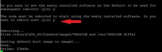
Note: When installing new software, the system might perform firmware upgrades to the BIOS and adapter cards, causing reboots and possible stops at the Loader-A prompt. If these actions occur, the system might deviate from this procedure.
Note: During the ONTAP installation a prompt to reboot the node requests a Y/N response.
Step 15. Press Ctrl-C when the following message displays:
Press Ctrl-C for Boot Menu
Step 16. Select option 4 for Clean Configuration and Initialize All Disks.
Step 17. Enter y to zero disks, reset config, and install a new file system.
Step 18. Enter yes to erase all the data on the disks.
Note: When initialization and creation of root aggregate is complete, the storage system reboots. You can continue with the configuration of node 02 while the initialization and creation of the root aggregate for node 01 is in progress. For more information about root aggregate and disk partitioning, please refer to the following NetApp ONTAP documentation on root-data partitioning: https://docs.netapp.com/us-en/ontap/concepts/root-data-partitioning-concept.html
Procedure 2. Configure Node 02
Step 1. Connect to the storage system console port. You should see a Loader-B prompt. However, if the storage system is in a reboot loop, press Ctrl-C to exit the autoboot loop when the following message displays:
Starting AUTOBOOT press Ctrl-C to abort…
Step 2. Allow the system to boot up.
autoboot
Step 3. Press Ctrl-C when prompted.
Note: If NetApp ONTAP 9.12.1P4 is not the version of the software being booted, continue with the following steps to install new software. If NetApp ONTAP 9.12.1P4 is the version being booted, select option 8 and y to reboot the node. Continue with section Set Up Node.
Step 4. To install new software, select option 7.
Step 5. Enter y to continue the installation.
Step 6. Select e0M for the network port you want to use for the download.
Step 7. Enter n to skip the reboot.
Step 8. Select option 7: Install new software first
Step 9. Enter y to continue the installation.
Step 10. Enter the IP address, netmask, and default gateway for e0M.
Enter the IP address for port e0M: <node02-mgmt-ip>
Enter the netmask for port e0M: <node02-mgmt-mask>
Enter the IP address of the default gateway: <node02-mgmt-gateway>
Step 11. Enter the URL where the software can be found.
Note: The web server must be reachable (ping) from node 02.
<url-boot-software>
Step 12. Press Enter for the username, indicating no username.
Step 13. Enter y to set the newly installed software as the default to be used for subsequent reboots.
Step 14. Enter y to reboot the node now.
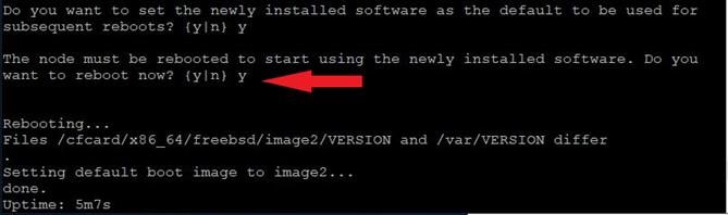
Note: When installing new software, the system might perform firmware upgrades to the BIOS and adapter cards, causing reboots and possible stops at the Loader-B prompt. If these actions occur, the system might deviate from this procedure.
Note: During the ONTAP installation a prompt to reboot the node requests a Y/N response.
Step 15. Press Ctrl-C when you see this message:
Press Ctrl-C for Boot Menu
Step 16. Select option 4 for Clean Configuration and Initialize All Disks.
Step 17. Enter y to zero disks, reset config, and install a new file system.
Step 18. Enter yes to erase all the data on the disks.
Note: When initialization and creation of root aggregate is complete, the storage system reboots. For more information about root aggregate and disk partitioning, please refer to the following ONTAP documentation on root-data partitioning. https://docs.netapp.com/us-en/ontap/concepts/root-data-partitioning-concept.html
Step 1. From a console port program attached to the storage controller A (node 01) console port, run the node setup script. This script appears when ONTAP 9.12.1 boots on the node for the first time.
Step 2. Follow the prompts to set up node 01.
Welcome to the cluster setup wizard.
You can enter the following commands at any time:
"help" or "?" - if you want to have a question clarified,
"back" - if you want to change previously answered questions, and
"exit" or "quit" - if you want to quit the setup wizard.
Any changes you made before quitting will be saved.
You can return to cluster setup at any time by typing “cluster setup”.
To accept a default or omit a question, do not enter a value.
This system will send event messages and weekly reports to NetApp Technical Support.
To disable this feature, enter "autosupport modify -support disable" within 24 hours.
Enabling AutoSupport can significantly speed problem determination and resolution should a problem occur on your system.
For further information on AutoSupport, see:
http://support.netapp.com/autosupport/
Type yes to confirm and continue {yes}: yes
Enter the node management interface port [e0M]: Enter
Enter the node management interface IP address: <node01-mgmt-ip>
Enter the node management interface netmask: <node01-mgmt-mask>
Enter the node management interface default gateway: <node01-mgmt-gateway>
A node management interface on port e0M with IP address <node01-mgmt-ip> has been created.
Use your web browser to complete cluster setup by accesing https://<node01-mgmt-ip>
Otherwise press Enter to complete cluster setup using the command line interface:
Step 3. To complete cluster setup, open a web browser and navigate to https://<node01-mgmt-ip>.
Table 5. Cluster Create in ONTAP Prerequisites
| Cluster Detail |
Cluster Detail Value |
| Cluster name |
<clustername> |
| Cluster Admin SVM |
<cluster-adm-svm> |
| Infrastructure Data SVM |
<infra-data-svm> |
| ONTAP base license |
<cluster-base-license-key> |
| Cluster management IP address |
<clustermgmt-ip> |
| Cluster management netmask |
<clustermgmt-mask> |
| Cluster management gateway |
<clustermgmt-gateway> |
| Cluster node 01 IP address |
<node01-mgmt-ip> |
| Cluster node 01 netmask |
<node01-mgmt-mask> |
| Cluster node 01 gateway |
<node01-mgmt-gateway> |
| Cluster node 02 IP address |
<node02-mgmt-ip> |
| Cluster node 02 netmask |
<node02-mgmt-mask> |
| Cluster node 02 gateway |
<node02-mgmt-gateway> |
| Node 01 service processor IP address |
<node01-sp-ip> |
| Node 01 service processor network mask |
<node01-sp-mask> |
| Node 01 service processor gateway |
<node01-sp-gateway> |
| Node 02 service processor IP address |
<node02-sp-ip> |
| Node 02 service processor network mask |
<node02-sp-mask> |
| Node 02 service processor gateway |
<node02-sp-gateway> |
| Node 01 node name |
<st-node01> |
| Node 02 node name |
<st-node02> |
| DNS domain name |
<dns-domain-name> |
| DNS server IP address |
<dns-ip> |
| NTP server A IP address |
<switch-a-ntp-ip> |
| NTP server B IP address |
<switch-b-ntp-ip> |
| SNMPv3 User |
<snmp-v3-usr> |
| SNMPv3 Authentication Protocol |
<snmp-v3-auth-proto> |
| SNMPv3 Privacy Protocol |
<snmpv3-priv-proto> |
Note: Cluster setup can also be performed using the CLI. This document describes the cluster setup using the NetApp ONTAP System Manager guided setup.
Step 4. Complete the required information on the Initialize Storage System screen:
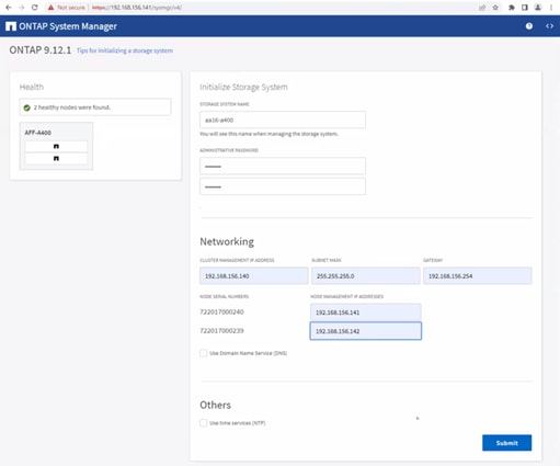
a. Enter the cluster name and administrator password.
b. Complete the Networking information for the cluster and each node.
Note: Here, the DNS and NTP server manual configuration for the cluster is optional. Ansible scripts will configure the same when ONTAP playbook with the tag “ontap_config_part_1” is executed.
Note: The nodes should be discovered automatically; if they are not, Refresh the browser page. By default, the cluster interfaces are created on all the new factory shipping storage controllers.
Note: If all the nodes are not discovered, then configure the cluster using the command line.
Note: The node management interface can be on the same subnet as the cluster management interface, or it can be on a different subnet. In this document, we assume that it is on the same subnet.
Step 5. Click Submit.
Note: A few minutes will pass while the cluster is configured. You can use Ansible scripts at this point to configure the ONTAP Storage Configuration via Ansible.
Procedure 4. Ansible ONTAP Storage Configuration - Part 1
Step 1. Edit the following variable files to ensure proper ONTAP Storage variables are entered:
● FlexPod-IMM-VMware/FlexPod-IMM-VMware/group_vars/secrets.yml
● FlexPod-IMM-VMware/FlexPod-IMM-VMware/inventory
● FlexPod-IMM-VMware/FlexPod-IMM-VMware/group_vars/all.yml
● FlexPod-IMM-VMware/FlexPod-IMM-VMware/group_vars/ontap
● FlexPod-IMM-VMware/FlexPod-IMM-VMware/vars/ontap_main.yml
Step 2. From FlexPod-IMM-VMware/FlexPod-IMM-VMware, run the Setup_ONTAP.yml Ansible playbook with the associated tag for this section:
ansible-playbook -i inventory Setup_ONTAP.yml -t ontap_config_part_1
Note: Use the -vvv tag to see detailed execution output log.
Cisco Intersight Managed Mode Configuration
This chapter contains the following:
● Set up Cisco Intersight Managed Mode on Cisco UCS Fabric Interconnects
● Set up Cisco Intersight Account
● Set up Cisco Intersight Licensing
● Set Up Cisco Intersight Resource Group
● Set Up Cisco Intersight Organization
● Claim Cisco UCS Fabric Interconnects in Cisco Intersight
● Verify Addition of Cisco UCS Fabric Interconnects to Cisco Intersight
● Upgrade Fabric Interconnect Firmware using Cisco Intersight
● Configure a Cisco UCS Domain Profile
● Create and Apply VLAN Policy
● Create and Apply VSAN Policy (FC configuration only)
● Configure FC Port Channel (FC configuration only)
● Port Configuration for Fabric Interconnect B
● Configure Network Connectivity Policy
● Summary
● Deploy the Cisco UCS Domain Profile
● Verify Cisco UCS Domain Profile Deployment
● Ansible Cisco UCS IMM Configuration
● Cisco UCS IMM Setup Completion
The Cisco Intersight platform is a management solution delivered as a service with embedded analytics for Cisco and third-party IT infrastructures. The Cisco Intersight Managed Mode (also referred to as Cisco IMM or Intersight Managed Mode) is an architecture that manages Cisco Unified Computing System (Cisco UCS) fabric interconnect–attached systems through a Redfish-based standard model. Cisco Intersight managed mode standardizes both policy and operation management for Cisco UCS C-Series M7 and Cisco UCS X210c M7 compute nodes used in this deployment guide.
Cisco UCS B-Series M6 servers, connected and managed through Cisco UCS FIs, are also supported by IMM. For a complete list of supported platforms, go to: https://www.cisco.com/c/en/us/td/docs/unified_computing/Intersight/b_Intersight_Managed_Mode_Configuration_Guide/b_intersight_managed_mode_guide_chapter_01010.html
Procedure 1. Set up Cisco Intersight Managed Mode on Cisco UCS Fabric Interconnects
The Cisco UCS fabric interconnects need to be set up to support Cisco Intersight Managed Mode. When converting an existing pair of Cisco UCS fabric interconnects from Cisco UCS Manager mode to Intersight Managed Mode (IMM), first erase the configuration and reboot your system.
Note: Converting fabric interconnects to Cisco Intersight managed mode is a disruptive process, and configuration information will be lost. You are encouraged to make a backup of their existing configuration.
Step 1. Configure Fabric Interconnect A (FI-A). On the Basic System Configuration Dialog screen, set the management mode to Intersight. The remaining settings are similar to those for the Cisco UCS Manager Managed mode (UCSM-Managed).
Cisco UCS Fabric Interconnect A
To configure the Cisco UCS for use in a FlexPod environment in ucsm managed mode, follow these steps:
1. Connect to the console port on the first Cisco UCS fabric interconnect.
Enter the configuration method. (console/gui) ? console
Enter the management mode. (ucsm/intersight)? intersight
The Fabric interconnect will be configured in the intersight managed mode. Choose (y/n) to proceed: y
Enforce strong password? (y/n) [y]: Enter
Enter the password for "admin": <password>
Confirm the password for "admin": <password>
Enter the switch fabric (A/B) []: A
Enter the system name: <ucs-cluster-name>
Physical Switch Mgmt0 IP address : <ucsa-mgmt-ip>
Physical Switch Mgmt0 IPv4 netmask : <ucs-mgmt-mask>
IPv4 address of the default gateway : <ucs-mgmt-gateway>
DNS IP address : <dns-server-1-ip>
Configure the default domain name? (yes/no) [n]: y
Default domain name : <ad-dns-domain-name>
Following configurations will be applied:
Management Mode=intersight
Switch Fabric=A
System Name=<ucs-cluster-name>
Enforced Strong Password=yes
Physical Switch Mgmt0 IP Address=<ucsa-mgmt-ip>
Physical Switch Mgmt0 IP Netmask=<ucs-mgmt-mask>
Default Gateway=<ucs-mgmt-gateway>
DNS Server=<dns-server-1-ip>
Domain Name=<ad-dns-domain-name>
Apply and save the configuration (select 'no' if you want to re-enter)? (yes/no): yes
Step 2. After applying the settings, make sure you can ping the fabric interconnect management IP address. When Fabric Interconnect A is correctly set up and is available, Fabric Interconnect B will automatically discover Fabric Interconnect A during its setup process as shown in the next step.
Step 3. Configure Fabric Interconnect B (FI-B). For the configuration method, select console. Fabric Interconnect B will detect the presence of Fabric Interconnect A and will prompt you to enter the admin password for Fabric Interconnect A. Provide the management IP address for Fabric Interconnect B and apply the configuration.
Cisco UCS Fabric Interconnect B
Enter the configuration method. (console/gui) ? console
Installer has detected the presence of a peer Fabric interconnect. This Fabric interconnect will be added to the cluster. Continue (y/n) ? y
Enter the admin password of the peer Fabric interconnect: <password>
Connecting to peer Fabric interconnect... done
Retrieving config from peer Fabric interconnect... done
Peer Fabric interconnect Mgmt0 IPv4 Address: <ucsa-mgmt-ip>
Peer Fabric interconnect Mgmt0 IPv4 Netmask: <ucs-mgmt-mask>
Peer FI is IPv4 Cluster enabled. Please Provide Local Fabric Interconnect Mgmt0 IPv4 Address
Physical Switch Mgmt0 IP address : <ucsb-mgmt-ip>
Apply and save the configuration (select 'no' if you want to re-enter)? (yes/no): yes
Procedure 2. Set up Cisco Intersight Account
Step 1. Go to https://intersight.com and click Create an account. Complete the log in process.
Step 2. Select the appropriate Region and click Next.
Step 3. Read and accept the license agreement. Click Next.
Step 4. Provide an Account Name and click Create.
With a successful creation of the Intersight account, the following page will be displayed:
Note: You can also choose to add the Cisco UCS FIs to an existing Cisco Intersight account.
Procedure 3. Set up Cisco Intersight Licensing
Note: When setting up a new Cisco Intersight account (as explained in this document), the account needs to be enabled for Cisco Smart Software Licensing.
Step 1. Log into the Cisco Smart Licensing portal: https://software.cisco.com/software/smart-licensing/alerts.
Step 2. Verify that the correct virtual account is selected.
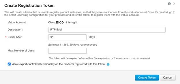
Step 3. Under Inventory > General, click New Token to generate a new token for product registration.
Step 4. Fill in the form and click Create Token. Copy this newly created token.
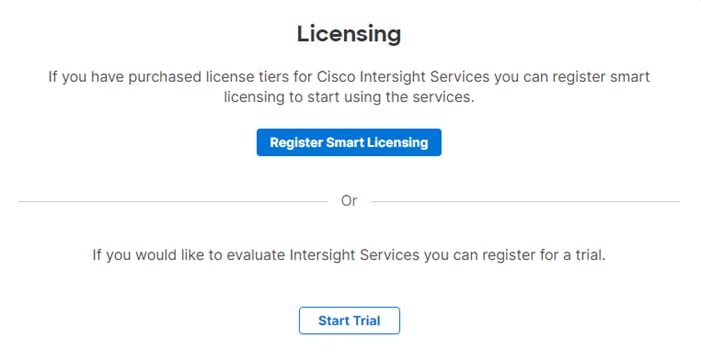
Step 5. In Cisco Intersight, if you created a new account, click Register Smart Licensing.
Step 6. Enter the copied token from the Cisco Smart Licensing portal. Click Next.
Step 7. With Enable Subscription Information selected, click Next. On the popup, click Allow.
Step 8. Select the products, you wish to enable (minimally Infrastructure Service). Use the pulldown to select the licenses or your Default Tier (for example, Advantage for all).
Step 9. From the Default Tier drop-down list select the license type (for example, Premier).
Step 10. Select Set Default Tier to all existing servers.
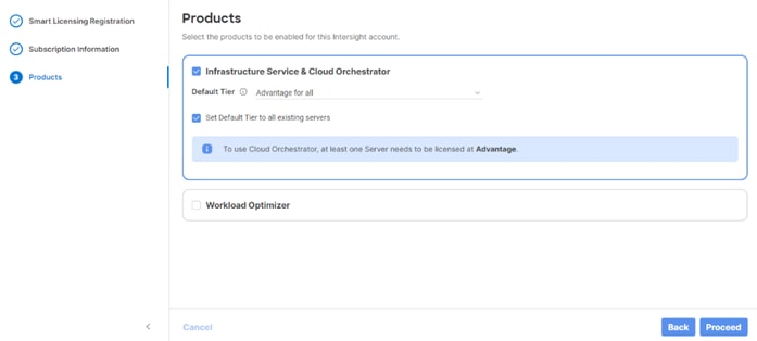
Step 11. Click Proceed then click Confirm.
Step 12. When the registration is successful, a Meet Intersight window will appear. Click Let’s Go to review the latest Intersight features or click Skip.
Procedure 4. Set Up Cisco Intersight Resource Group
In this procedure, a Cisco Intersight resource group is created where resources such as targets will be logically grouped. In this deployment, a single resource group is created to host all the resources, but you can choose to create multiple resource groups for granular control of the resources.
Step 1. Log into Cisco Intersight.
Step 2. Select System. On the left, click Settings (the gear icon).
Step 3. Click Resource Groups in the middle panel.
Step 4. Click + Create Resource Group in the top-right corner.
Step 5. Provide a name for the Resource Group (for example, AA02-rg).
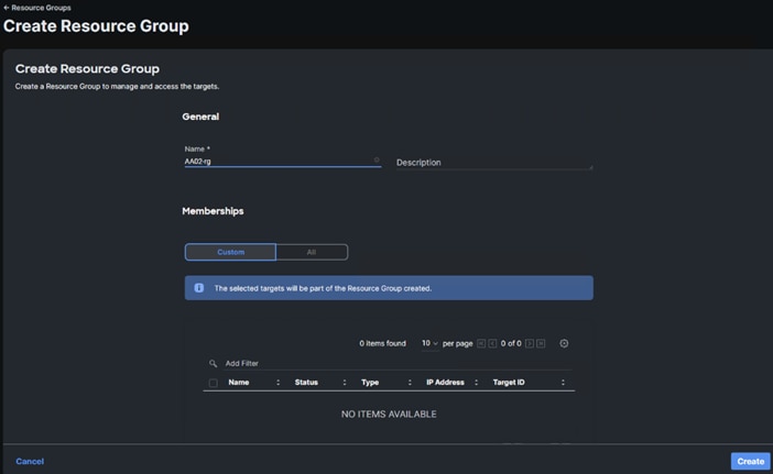
Step 6. Under Memberships, select Custom.
Step 7. Click Create.
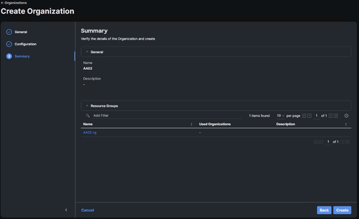
Procedure 5. Set Up Cisco Intersight Organization
In this procedure, an Intersight organization is created where all Cisco Intersight Managed Mode configurations including policies are defined.
Step 1. Log into the Cisco Intersight portal.
Step 2. Select System. On the left, click Settings (the gear icon).
Step 3. Click Organizations in the middle panel.
Step 4. Click + Create Organization in the top-right corner.
Step 5. Provide a name for the organization (for example, AA02), optionally select Share Resources with Other Organizations, and click Next.
Step 6. Select the Resource Group created in the last step (for example, AA02-rg) and click Next.
Step 7. Click Create.
Procedure 6. Claim Cisco UCS Fabric Interconnects in Cisco Intersight
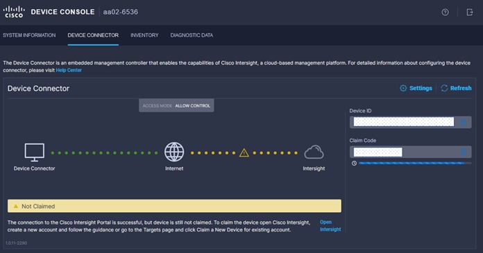
Make sure the initial configuration for the fabric interconnects has been completed. Log into the Fabric Interconnect A Device Console using a web browser to capture the Cisco Intersight connectivity information.
Step 1. Use the management IP address of Fabric Interconnect A to access the device from a web browser and the previously configured admin password to log into the device.
Step 2. Under DEVICE CONNECTOR, the current device status will show “Not claimed.” Note or copy, the Device ID, and Claim Code information for claiming the device in Cisco Intersight.
Step 3. Log into Cisco Intersight.
Step 4. Select System. On the left, click Administration > Targets.
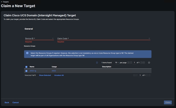
Step 5. Click Claim a New Target.
Step 6. Select Cisco UCS Domain (Intersight Managed) and click Start.
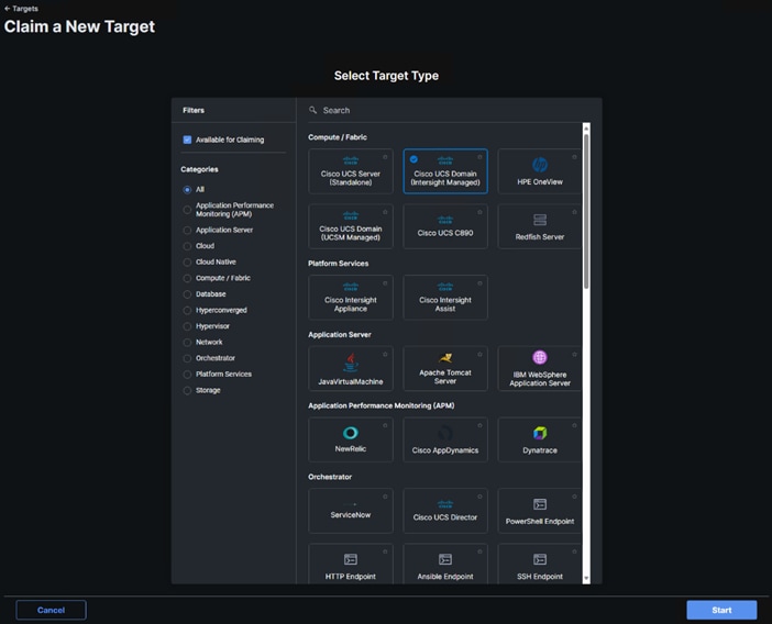
Step 7. Copy and paste the Device ID and Claim from the Cisco UCS FI to Intersight.
Step 8. Select the previously created Resource Group and click Claim.
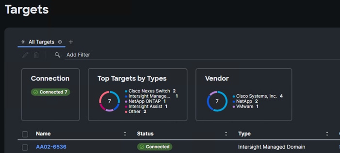
With a successful device claim, Cisco UCS FI should appear as a target in Cisco Intersight as shown below:
Procedure 7. Verify Addition of Cisco UCS Fabric Interconnects to Cisco Intersight
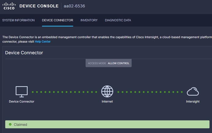
Step 1. Log into the web GUI of the Cisco UCS fabric interconnect and click the browser refresh button.
The fabric interconnect status should now be set to Claimed.
Procedure 8. Upgrade Fabric Interconnect Firmware using Cisco Intersight
If your Cisco UCS 6536 Fabric Interconnects are not already running firmware release 4.2(3d) (NX-OS version 9.3(5)I42(3c)), upgrade them to 4.2(3d) or later.
Step 1. Log into the Cisco Intersight portal.
Step 2. From the drop-down list, select Infrastructure Service and then select Fabric Interconnects under Operate on the left.
Step 3. Click the ellipses “…” at the end of the row for either of the Fabric Interconnects and select Upgrade Firmware.
Step 4. Click Start.
Step 5. Verify the Fabric Interconnect information and click Next.
Step 6. Enable Advanced Mode using the toggle switch and uncheck Fabric Interconnect Traffic Evacuation.
Step 7. Select 4.2(3d) release from the list and click Next.
Step 8. Verify the information and click Upgrade to start the upgrade process.
Step 9. Watch the Request panel of the main Intersight screen as the system will ask for user permission before upgrading each FI. Click on the Circle with Arrow and follow the prompts on screen to grant permission.
Step 10. Wait for both the FIs to successfully upgrade.
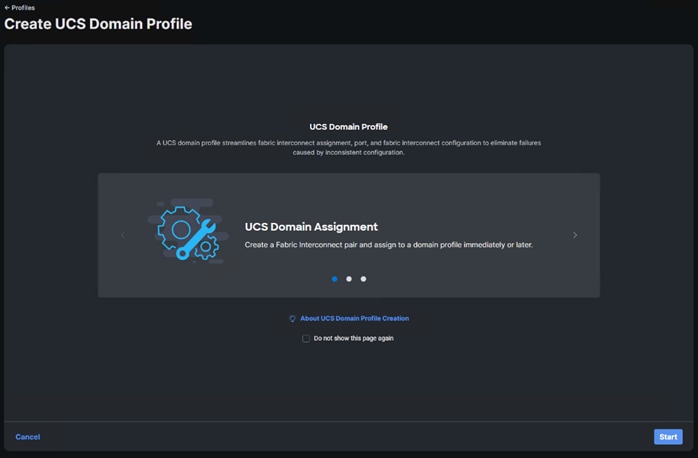
Procedure 9. Configure a Cisco UCS Domain Profile
Note: A Cisco UCS domain profile configures a fabric interconnect pair through reusable policies, allows configuration of the ports and port channels, and configures the VLANs and VSANs in the network. It defines the characteristics of and configured ports on fabric interconnects. The domain-related policies can be attached to the profile either at the time of creation or later. One Cisco UCS domain profile can be assigned to one fabric interconnect domain.
Step 1. Log into the Cisco Intersight portal.
Step 2. From the drop-down list, select Infrastructure Service and then under Configure select Profiles.
Step 3. In the main window, select UCS Domain Profiles and click Create UCS Domain Profile.
Step 4. From the Create UCS Domain Profile screen, click Start.
Procedure 10. General Configuration
Step 1. Select the organization from the drop-down list (for example, AA02).
Step 2. Provide a name for the domain profile (for example, AA02-6536-Domain-Profile).
Step 3. Provide an optional Description.
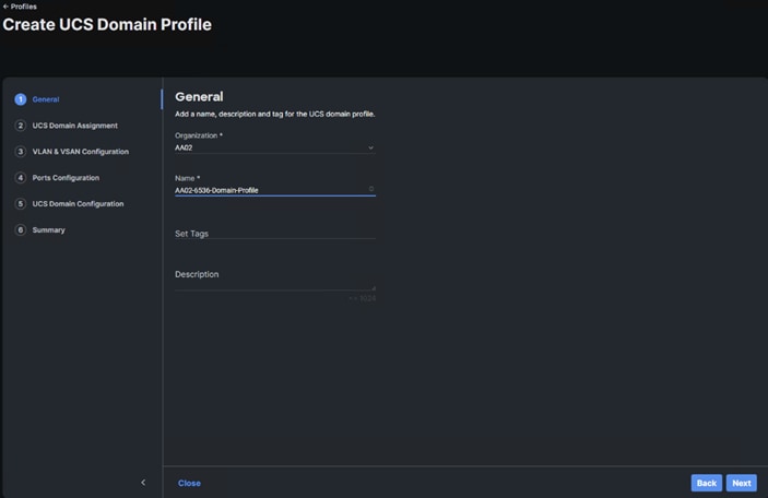
Step 4. Click Next.
Procedure 11. Cisco UCS Domain Assignment
Step 1. Assign the Cisco UCS domain to this new domain profile by clicking Assign Now and selecting the previously added Cisco UCS domain (for example, AA02-6536).
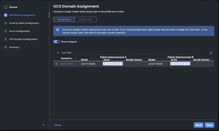
Step 2. Click Next.
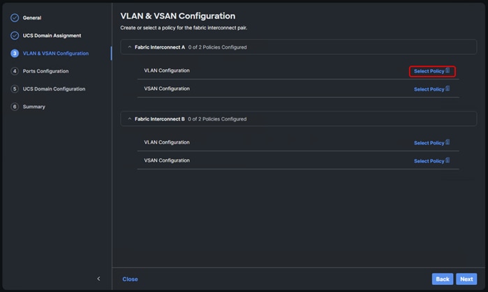
In this procedure, a single VLAN policy is created for both fabric interconnects and two individual VSAN policies are created because the VSAN IDs are unique for each fabric interconnect.
Procedure 1. Create and Apply VLAN Policy
Step 1. Click Select Policy next to VLAN Configuration under Fabric Interconnect A.
Step 2. In the pane on the right, click Create New.
Step 3. Verify the correct organization is selected from the drop-down list (for example, AA02) and provide a name for the policy (for example, AA02-6536-VLAN).
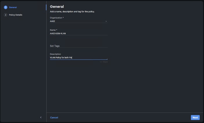
Step 4. Click Next.
Step 5. Click Add VLANs.
Step 6. Provide a name and VLAN ID for the native VLAN.
Step 7. Make sure Auto Allow On Uplinks is enabled.
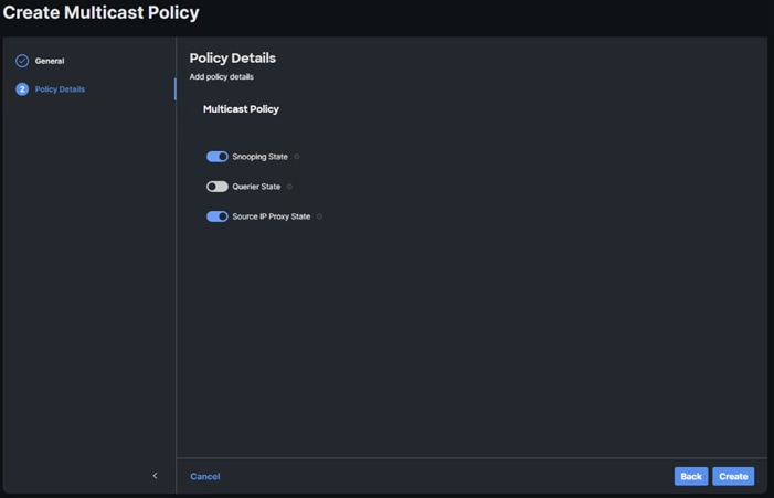
Step 8. To create the required Multicast policy, under Multicast, click Select Policy.
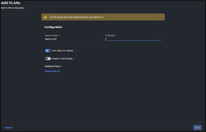
Step 9. In the window on the right, click Create New to create a new Multicast Policy.
Step 10. Provide a Name for the Multicast Policy (for example, AA02-MCAST).
Step 11. Provide an optional Description and click Next.
Step 12. Leave the default settings and click Create.
Step 13. Click Add VLANs to add the VLAN.
Step 14. Select Set Native VLAN ID and enter the VLAN number (for example, 2) under VLAN ID.
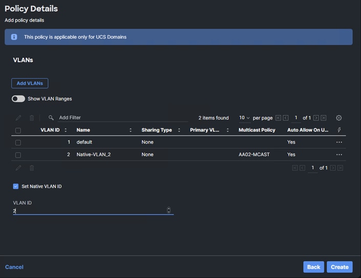
Step 15. Add the remaining VLANs for FlexPod by clicking Add VLANs and entering the VLANs one by one. Reuse the previously created multicast policy for all the VLANs.
The VLANs created during this validation are shown below:
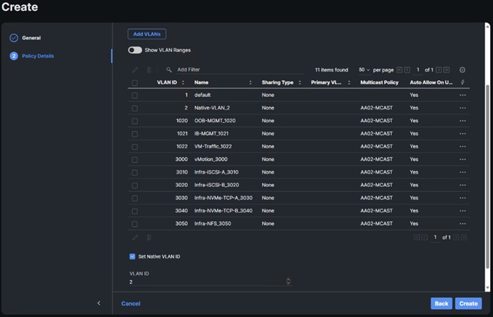
Note: The iSCSI and NVMe-TCP VLANs shown in the screen image above are only needed when iSCSI and NVME-TCP are configured in the environment.
Step 16. Click Create to finish creating the VLAN policy and associated VLANs.
Step 17. Click Select Policy next to VLAN Configuration for Fabric Interconnect B and select the same VLAN policy.
Procedure 2. Create and Apply VSAN Policy (FC configuration only)
Step 1. Click Select Policy next to VSAN Configuration under Fabric Interconnect A and click Create New.
Step 2. Verify the correct organization is selected from the drop-down list (for example, AA02) and provide a name for the policy (for example, AA02-6536-VSAN-Pol-A).
Note: A separate VSAN-Policy is created for each fabric interconnect.
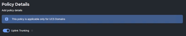
Step 3. Click Next.
Step 4. Optional: enable Uplink Trunking.
Step 5. Click Add VSAN and provide a name (for example, VSAN-A), VSAN ID (for example, 101), and associated Fibre Channel over Ethernet (FCoE) VLAN ID (for example, 101) for SAN A.
Step 6. Set VLAN Scope as Uplink.
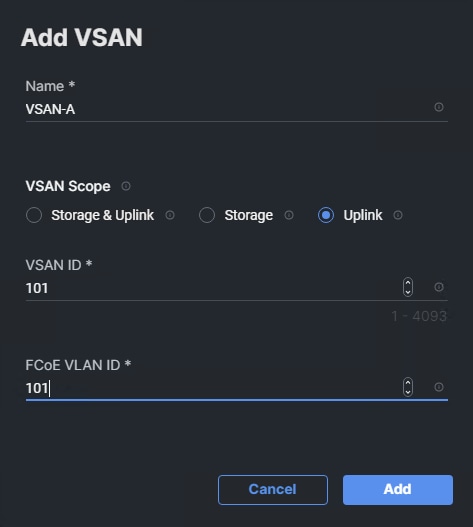
Step 7. Click Add.
Step 8. Click Create to finish creating VSAN policy for fabric A.
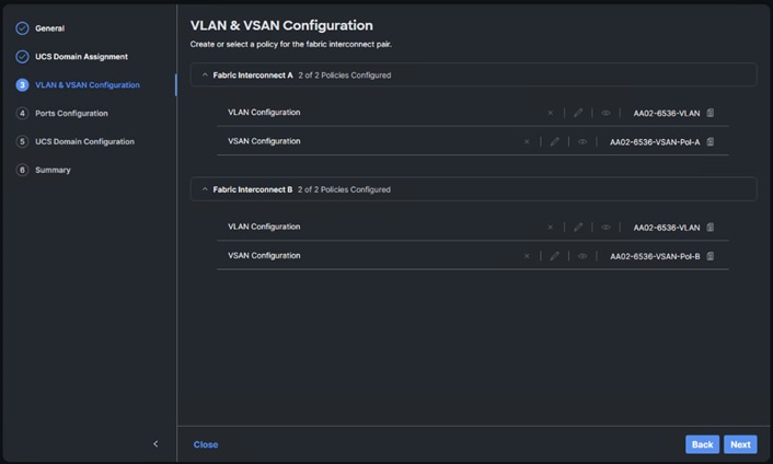
Step 9. Repeat steps 1 - 8 to create a new VSAN policy for SAN-B. Name the policy to identify the SAN-B configuration (for example, AA02-6536-VSAN-Pol-B) and use appropriate VSAN and FCoE VLAN (for example, 102).
Step 10. Verify that a common VLAN policy and two unique VSAN policies are associated with the two fabric interconnects.
Step 11. Click Next.
Procedure 3. Ports Configuration
Step 1. Click Select Policy for Fabric Interconnect A.
Step 2. Click Create New in the pane on the right to define a new port configuration policy.
Note: Use two separate port policies for the fabric interconnects. Using separate policies provide flexibility when port configuration (port numbers or speed) differs between the two FIs. When configuring Fibre Channel, two port policies are required because each fabric interconnect uses a unique Fibre Channel VSAN ID.
Step 3. Verify correct organization is selected from the drop-down list (for example, AA02) and provide a name for the policy (for example, AA02-6536-PortPol-A). Select the UCS-FI-6536 Switch Model.
Step 4. Click Next.
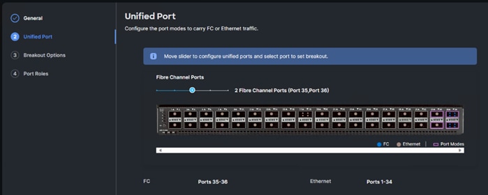
Step 5. Move the slider to set up unified ports. In this deployment, the last two ports were selected as Fibre Channel ports as 4x32G breakouts. Click Next.
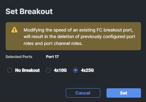
Step 6. If any ethernet ports need to be configured as breakouts, either 4x25G or 4x10G, for connecting Cisco UCS C-Series servers or a Cisco UCS 5108 chassis, configure them here. In the list, select the checkbox next to any ports that need to be configured as breakout or select the ports on the graphic. When all ports are selected, click Configure.
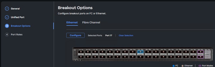
Step 7. In the Set Breakout popup, select either 4x10G or 4x25G and click Set.
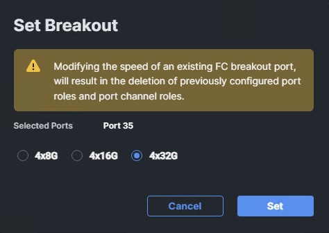
Step 8. Under Breakout Options, select Fibre Channel. Select any ports that need the speed changed from 16G to 32G and click Configure.
Step 9. In the Set Breakout popup, select 4x32G and click Set.
Step 10. Click Next.
Step 11. From the list, check the box next to any ports that need to be configured as server ports, including ports connected to chassis or Cisco UCS C-Series servers. Ports can also be selected on the graphic. When all ports are selected, click Configure. Breakout and non-breakout ports cannot be configured together. If you need to configure breakout and non-breakout ports, do this configuration in two steps.
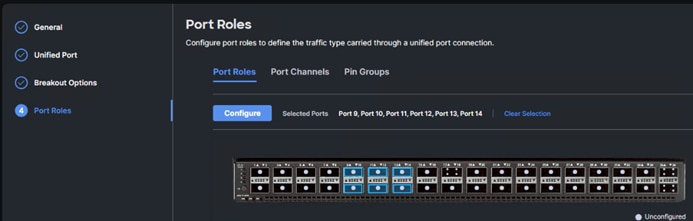
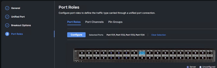
Step 12. From the drop-down list, select Server as the role. Also, unless you are using a Cisco Nexus 93360YC-FX23 as a FEX, leave Auto Negotiation enabled. If you need to do manual number of chassis or Cisco UCS C-Series Servers, enable Manual Chassis/Server Numbering.
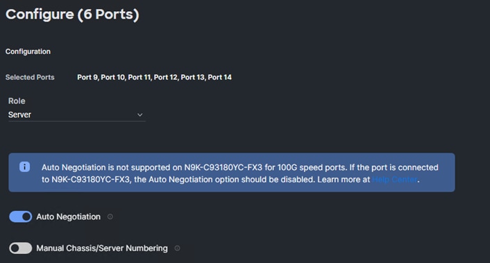
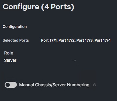
Step 13. Click Save.
Step 14. Configure the Ethernet uplink port channel by selecting Port Channels in the main pane and then clicking Create Port Channel.
Step 15. Select Ethernet Uplink Port Channel as the role, provide a port-channel ID (for example, 131), and select a value for Admin Speed from drop-down list (for example, Auto).
Note: You can create the Ethernet Network Group, Flow Control, Link Aggregation for defining disjoint Layer-2 domain or fine tune port-channel parameters. These policies were not used in this deployment and system default values were utilized.
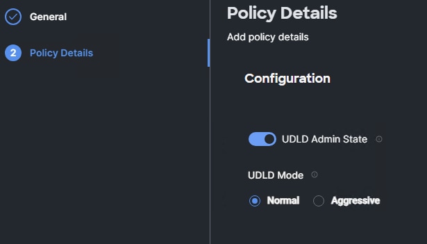
Step 16. Under Link Control, click Select Policy then click Create New.
Step 17. Verify the correct organization is selected from the drop-down list (for example, AA02) and provide a name for the policy (for example, AA02-UDLD-Link-Control). Click Next.
Step 18. Leave the default values selected and click Create.
Step 19. Scroll down and select uplink ports from the list of available ports (for example, port 31 and 32)
Step 20. Click Save.
Procedure 4. Configure FC Port Channel (FC configuration only)
Note: FC uplink port channels are only needed when configuring FC SAN and can be skipped for IP-only (iSCSI) storage access.
Step 1. Configure a Fibre Channel Port Channel by selecting the Port Channel in the main pane again and clicking Create Port Channel.
Step 2. From the Role drop-down list, select FC Uplink Port Channel.
Step 3. Provide a port-channel ID (for example, 135), select a value for Admin Speed (for example, 32Gbps), and provide a VSAN ID (for example, 101).
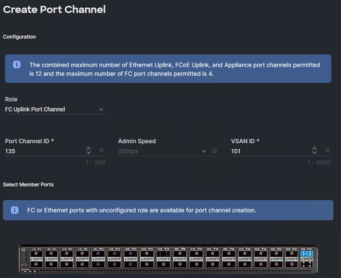
Step 4. Select ports (for example, 35/1,35/2,35/3,35/4).
Step 5. Click Save.
Step 6. Verify the port-channel IDs and ports after both the Ethernet uplink port channel and the Fibre Channel uplink port channel have been created.
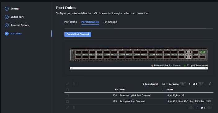
Step 7. Click Save to create the port policy for Fabric Interconnect A.
Note: Use the summary screen to verify that the ports were selected and configured correctly.
Procedure 5. Port Configuration for Fabric Interconnect B
Step 1. Repeat the steps in Ports Configuration and Configure FC Port Channel to create the port policy for Fabric Interconnect B including the Ethernet port-channel and the FC port-channel (if configuring SAN). Use the following values for various parameters:
● Name of the port policy: AA02-PortPol-B
● Ethernet port-Channel ID: 132
● FC port-channel ID: 135
● FC VSAN ID: 102
Step 2. When the port configuration for both fabric interconnects is complete and looks good, click Next.
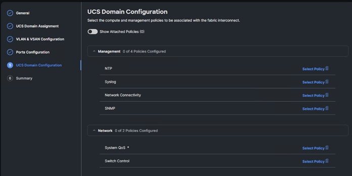
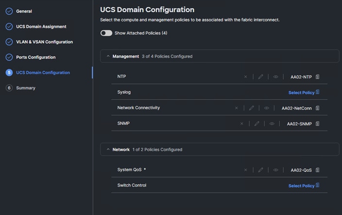
Procedure 6. UCS Domain Configuration
Under UCS domain configuration, additional policies can be configured to setup NTP, Syslog, DNS settings, SNMP, QoS and UCS operating mode (end host or switch mode). For this deployment, four policies (NTP, Network Connectivity, SNMP, and System QoS) will be configured, as shown below:
Procedure 7. Configure NTP Policy
Step 1. Click Select Policy next to NTP and then, in the pane on the right, click Create New.
Step 2. Verify correct organization is selected from the drop-down list (for example, AA02) and provide a name for the policy (for example, AA02-NTP).
Step 3. Click Next.
Step 4. Enable NTP, provide the first NTP server IP address, and select the time zone from the drop-down list.
Step 5. Add a second NTP server by clicking + next to the first NTP server IP address.
Note: The NTP server IP addresses should be Nexus switch management IPs. NTP distribution was configured in the Cisco Nexus switches.
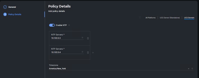
Step 6. Click Create.
Procedure 8. Configure Network Connectivity Policy
Step 1. Click Select Policy next to Network Connectivity and then, in the pane on the right, click Create New.
Step 2. Verify correct organization is selected from the drop-down list (for example, AA02) and provide a name for the policy (for example, AA02-NetConn).
Step 3. Click Next.
Step 4. Provide DNS server IP addresses for Cisco UCS (for example, 10.102.1.151 and 10.102.1.152).
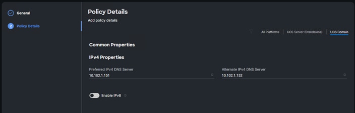
Step 5. Click Create.
Procedure 9. Configure SNMP Policy
Step 1. Click Select Policy next to SNMP and then, in the pane on the right, click Create New.
Step 2. Verify correct organization is selected from the drop-down list (for example, AA02) and provide a name for the policy (for example, AA02-SNMP).
Step 3. Click Next.
Step 4. Provide a System Contact email address, a System Location, and optional Community Strings.
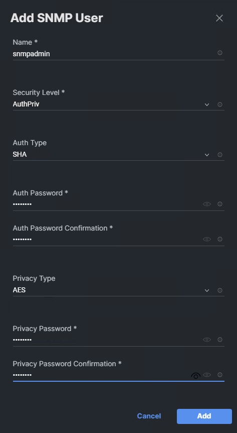
Step 5. Under SNMP Users, click Add SNMP User.
Step 6. This user id will be used for Cisco DCNM SAN to query the UCS Fabric Interconnects. Fill in a user name (for example, snmpadmin), Auth Type SHA, an Auth Password with confirmation, Privacy Type AES, and a Privacy Password with confirmation. Click Add.
Step 7. Optional: Add an SNMP Trap Destination (for example, the DCNM SAN IP Address). If the SNMP Trap Destination is V2, you must add Trap Community String.
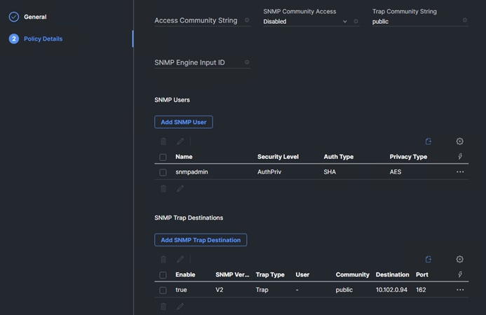
Step 8. Click Create.
Procedure 10. Configure System QoS Policy
Step 1. Click Select Policy next to System QoS* and in the pane on the right, click Create New.
Step 2. Verify correct organization is selected from the drop-down list (for example, AA02) and provide a name for the policy (for example, AA02-QoS).
Step 3. Click Next.
Step 4. Change the MTU for Best Effort class to 9216.
Step 5. Keep the default selections or change the parameters if necessary.
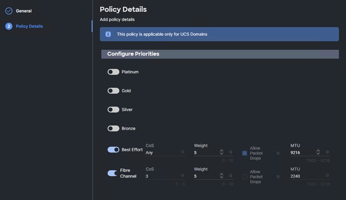
Step 6. Click Create.
Step 7. Click Next.
Step 1. Verify all the settings including the fabric interconnect settings, by expanding the settings and make sure that the configuration is correct.
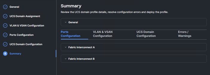
Procedure 12. Deploy the Cisco UCS Domain Profile
Step 1. From the UCS domain profile Summary view, click Deploy.
Step 2. Acknowledge any warnings and click Deploy again.
Note: The system will take some time to validate and configure the settings on the fabric interconnects. Log into the fabric interconnect serial console servers to see when the Cisco UCS fabric interconnects have finished configuration and are successfully rebooted.
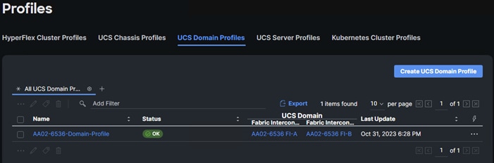
Procedure 13. Verify Cisco UCS Domain Profile Deployment
When the Cisco UCS domain profile has been successfully deployed, the Cisco UCS chassis and the blades should be successfully discovered.
Note: It takes a while to discover the blades and rackmounts for the first time. Watch the number of outstanding requests in Cisco Intersight.
Step 1. Log into Cisco Intersight. Under Infrastructure Service > Configure > Profiles > UCS Domain Profiles, verify that the domain profile has been successfully deployed.
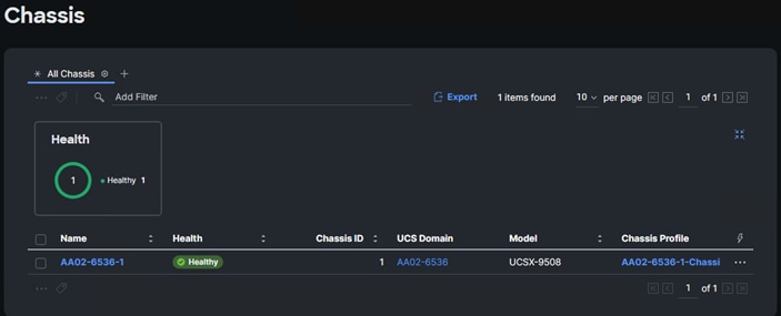
Step 2. Verify that the chassis (either UCSX-9508 or UCS 5108 chassis) has been discovered and is visible under Infrastructure Service > Operate > Chassis.
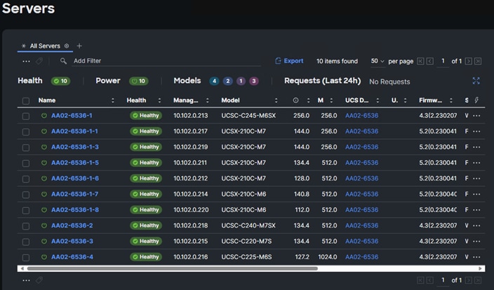
Step 3. Verify that the servers have been successfully discovered and are visible under Infrastructure Service > Operate > Servers.
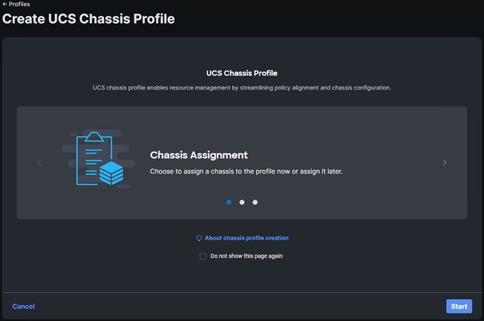
Procedure 14. Configure a Cisco UCS Chassis Profile
Note: A Cisco UCS chassis profile configures either a UCS X9508 or UCS 5108 chassis through reusable policies. It defines the characteristics of power distribution and fan configuration in the chassis. One Cisco UCS chassis profile can be assigned to one chassis.
Step 1. Log into the Cisco Intersight portal.
Step 2. From the drop-down list, select Infrastructure Service, then under Configure select Profiles.
Step 3. In the main window, select UCS Chassis Profiles and click Create UCS Chassis Profile.
Step 4. From the Create UCS Chassis Profile screen, click Start.
Procedure 15. UCS Chassis Profile General Configuration
Step 1. Select the organization from the drop-down list (for example, AA02).
Step 2. Provide a name for the domain profile (for example, AA02-6536-1-Chassis-Profile).
Step 3. Provide an optional Description.
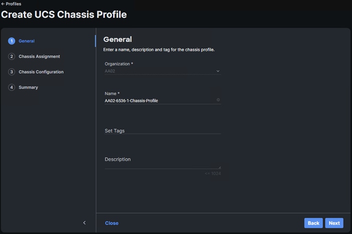
Step 4. Click Next.
Procedure 16. Cisco UCS Chassis Assignment
Step 1. Assign the Cisco UCS chassis to this new chassis profile by clicking Assign Now and selecting a Cisco UCS chassis (for example, AA02-6536-1).
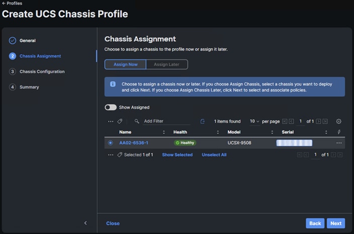
Step 2. Click Next.
Procedure 17. Create and Apply Power Policy
Step 1. Click Select Policy next to Power.
Step 2. Click Create New to create a new policy.
Step 3. Make sure the correct Organization (for example, AA02) is selected.
Step 4. Enter a Name for the policy (for example, AA02-Chassis-Server-Power). Optionally, enter a Description.
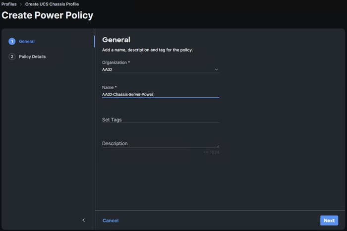
Step 5. Click Next.
Step 6. Select All Platforms. It is recommended to leave all settings at their defaults, but the settings can be adjusted later according to performance and sustainability requirements.
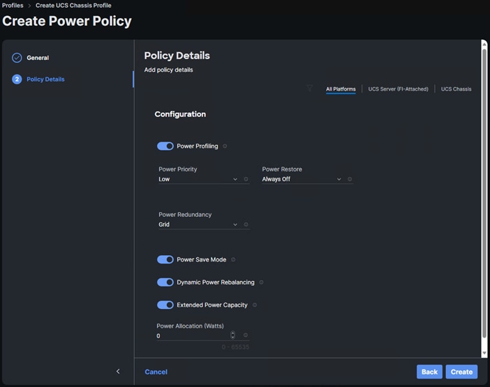
Step 7. Click Create to create the power policy.
Procedure 18. Create and Apply Thermal Policy
Step 1. Click Select Policy next to Thermal.
Step 2. Click Create New to create a new policy.
Step 3. Make sure the correct Organization (for example, AA02) is selected.
Step 4. Enter a Name for the policy (for example, AA02-Chassis-Thermal). Optionally, enter a Description.
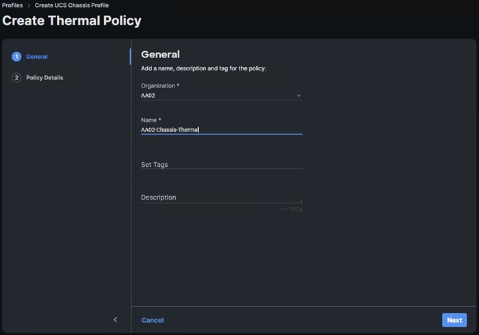
Step 5. Click Next.
Note: It is recommended to leave all settings at their defaults, but the settings can be adjusted later according to performance and sustainability requirements.
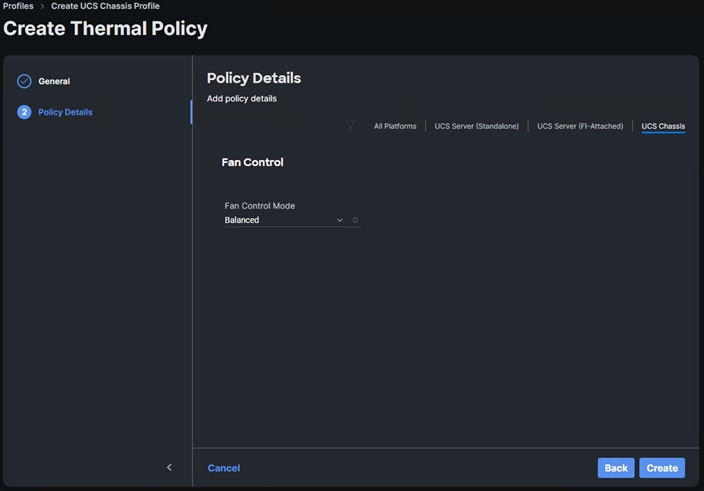
Step 6. Click Create to create the thermal policy.
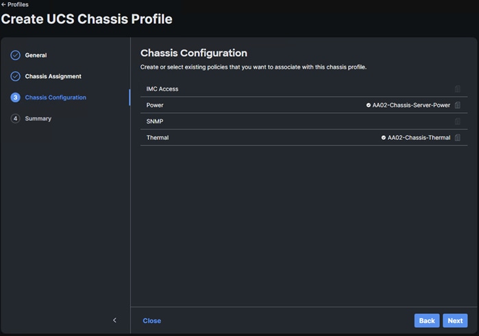
Step 7. Click Next.
Procedure 19. Complete UCS Chassis Profile and Deploy
Step 1. Review the UCS Chassis Profile Summary and click Deploy. Click Deploy again to deploy the profile.
Step 2. When deployment is complete, the profile Status will show OK.
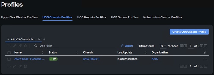
Note: This set of procedures can be used to create profiles for additional chassis. In these additional chassis profiles, the power and thermal policies can be reused as needed.
Procedure 20. Ansible Cisco UCS IMM Configuration
To configure the Cisco UCS from the Ansible management workstation, follow the steps in this procedure. The group_vars/ucs.yml file contains two important variables:
● server_cpu_type – Intel or AMD – the type of CPU in the server
● vic_type – 4G or 5G – 5G is the latest 15000-series VICs while 4G is all previous generations
Step 1. To execute the playbooks against your Intersight account, you need to create an API key and save a SecretKey.txt file from your Cisco Intersight account:
a. In Cisco Intersight, select System > Settings > API > API Keys.
b. Click Generate API Key.
c. Under Generate API Key, enter a Description (for example, API Key for Ansible) and select API key for OpenAPI schema version 2. Click Generate.
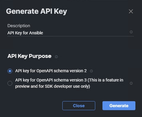
d. In the Generate API Key window, click the upper ![]() icon to copy the API Key ID to the clipboard. Paste this key into the api_key_id variable in the FlexPod-IMM-VMware/FlexPod-IMM-VMware/group_vars/ucs.yml variable file and save it.
icon to copy the API Key ID to the clipboard. Paste this key into the api_key_id variable in the FlexPod-IMM-VMware/FlexPod-IMM-VMware/group_vars/ucs.yml variable file and save it.
e. Using an editor, open the FlexPod-IMM-VMware/FlexPod-IMM-VMware/SecretKey.txt file and clear all text from the file. Then click the lower ![]() icon in the Generate API Key window and paste the Secret Key into the SecretKey.txt file and save it.
icon in the Generate API Key window and paste the Secret Key into the SecretKey.txt file and save it.
Step 2. Edit the following variable files to ensure proper UCS variables are entered:
● FlexPod-IMM-VMware/FlexPod-IMM-VMware/group_vars/secrets.yml
● FlexPod-IMM-VMware/FlexPod-IMM-VMware/group_vars/all.yml
● FlexPod-IMM-VMware/FlexPod-IMM-VMware/group_vars/ucs.yml
● FlexPod-IMM-VMware/FlexPod-IMM-VMware/roles/UCS-IMM/create_pools/defaults/main.yml
● FlexPod-IMM-VMware/FlexPod-IMM-VMware/roles/UCS-IMM/create_server_policies/defaults/main.yml
● FlexPod-IMM-VMware/FlexPod-IMM-VMware/roles/UCS-IMM/create_server_profile_template/defaults/main.yml
Note: It is critical when entering values in the variable files that either the FC and FC-NVMe NetApp LIF WWPNs or Infrastructure SVM iSCSI IQN be entered into the all.yml file so that UCS SAN boot and MDS device alias can be properly configured. LIF WWPNs can be queried by connecting to the NetApp cluster CLI interface and running “network interface show -vserver <svm-name>.” If iSCSI SAN boot is being configured, the Infrastructure SVM’s iSCSI IQN can be queried by running “vserver iscsi show -vserver <svm-name>.”
Note: The /home/admin/FlexPod-IMM-VMware/FlexPod-IMM-VMware directory contains three Ansible playbooks to set up Cisco UCS IMM server profile templates: Create_IMM_Pools.yml, Create_IMM_Server_Policies.yml, and Create_IMM_Server_Profile_Templates.yml. Run Create_IMM_Pools.yml only once. Then Create_IMM_Server_Policies.yml and Create_IMM_Server_Profile_Templates.yml are designed to be run more than once with different combinations of server_cpu_type andvic_type. It is important when Create_IMM_Server_Policies.yml is run that Create_IMM_Server_Profiles_Templates.yml is run before changing the server_cpu_type and vic_type variables. Many of the policies and templates will be assigned unique names according to these variables. Since the UCS-IMM Ansible playbooks connect to the Cisco Intersight API website instead of hardware components, the use of the inventory file is not needed.
Step 3. To set up the Cisco Intersight IMM pools, policies, and server profile templates, run the following:
ansible-playbook ./Setup_IMM_Pools.yml
ansible-playbook ./Setup_IMM_Server_Policies.yml
ansible-playbook ./Setup_IMM_Server_Profile_Templates.yml
Note: Server Profiles will be generated from the Server Profile Templates and assigned to servers after the Cisco UCS IMM Ansible Configuration.
Cisco UCS IMM Setup Completion
Complete the following procedures whether performing an Ansible configuration or a Manual configuration of the FlexPod.
Procedure 1. Clone Server Profile Templates
Cisco UCS Power policies can only be applied to blade servers and Thermal policies can only be applied to rack mount servers. If you have both blades and rack mounts in your environment, it is necessary to clone existing Server Profile Templates to have a copy for each type of server. The original template can be used for blades and the copy for rack mounts.
Step 1. Go to Infrastructure Service > Configure > Templates, select a template (for example, AA02-M7-Intel-5G-VIC-iSCSI-Boot-Template), click … to the right on the same line, and click Clone.
Step 2. Leave the Number of Clones set to 1 and click Next.
Step 3. Enter a new Clone Name (for example AA02-CM7-Intel-5G-VIC-iSCSI-Boot-Template) and click Clone.
Step 4. Select the newly cloned template, click … to the right on the same line, and select Edit.
Step 5. Click Next. To the right of Thermal, click Select Policy.
Step 6. Either select the existing Thermal policy or click Create New and create a new Thermal policy with desired parameters for rack mount server fans.
Step 7. Once the policy is added, click Close at the bottom of the screen to save the edited template.
Procedure 2. Derive Server Profiles
Step 1. Go to Infrastructure Service > Configure > Templates, for any template that will be used for blades (either X-Series or B-Series), select the template (for example, AA02-M7-Intel-5G-VIC-iSCSI-Boot-Template), click … to the right on the same line, and select Edit.
Step 2. Click Next and then click Select Policy.
Step 3. Either select the existing Power policy or click Create New and create a new Power policy with desired parameters for blade servers.
Step 4. Once the policy is added, click Close to save the edited template.
Step 5. Repeat steps 1 - 4 for all templates that will be used with server blades.
Step 6. Go to Infrastructure Service > Configure > Templates, select the desired template (for example, AA02-M7-Intel-5G-VIC-iSCSI-Boot-Template), click … to the right on the same line, and select Derive Profiles.
Step 7. Under the Server Assignment, select Assign Now and select server(s) that match the template configuration. You can select one or more servers depending on the number of profiles to be deployed.
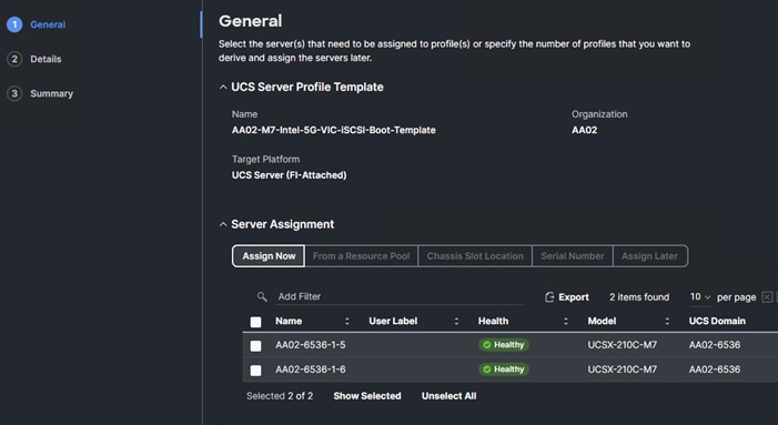
Step 8. Click Next.
Note: Cisco Intersight will fill in default information for the number of servers selected (2 in this case).
Step 9. Adjust the fields as needed. It is recommended to use the server hostname for the Server Profile name.
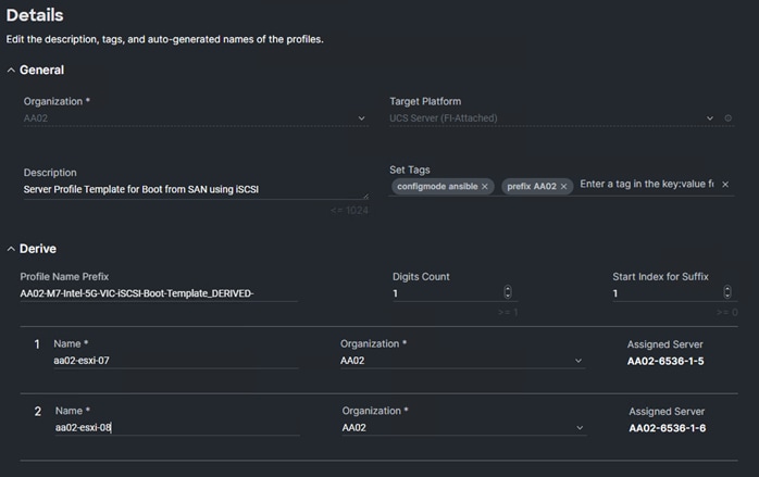
Step 10. Click Next.
Step 11. Verify the information and click Derive to create the Server Profile(s).
Step 12. From the Infrastructure Service > Configure > Profiles > UCS Server Profiles list, select the profile(s) just created and click the … at the top of the column and select Deploy. Click Deploy to confirm.
Step 13. Cisco Intersight will start deploying the server profile(s) and will take some time to apply all the policies. Use the Requests tab at the top right-hand corner of the window to see the progress.

When the Server Profile(s) are deployed successfully, they will appear under the Server Profiles with the status of OK.
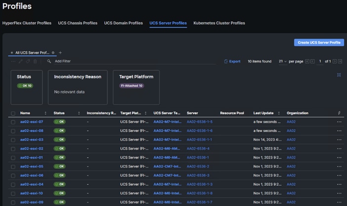
Step 14. Derive and Deploy all needed servers for your FlexPod environment.
Step 15. Select Infrastructure Service > Servers, select all Servers that have a Server Profile assigned. Click … at either the top or bottom of the table and select Power > Power On.
This chapter contains the following:
This chapter explains how to configure the Cisco MDS 9000s for use in a FlexPod environment. The configuration covered in this section is only needed when configuring Fibre Channel and FC-NVMe storage access.
Note: If FC connectivity is not required in the FlexPod deployment, this section can be skipped.
Note: If the Cisco Nexus 93360YC-FX2 switches are being used for SAN switching in this FlexPod Deployment, refer to section FlexPod with Cisco Nexus 93360YC-FX2 SAN Switching Configuration – Part 2 in the Appendix of this document.
Follow the physical connectivity guidelines for FlexPod as explained in Physical Topology section.
The following procedures describe how to configure the Cisco MDS switches for use in a base FlexPod environment. This procedure assumes you are using the Cisco MDS 9132T with NX-OS 9.3(2).
Procedure 1. Set up Cisco MDS 9132T A and 9132T B
Note: On initial boot and connection to the serial or console port of the switch, the NX-OS setup should automatically start and attempt to enter Power on Auto Provisioning. Enter y to get to the System Admin Account Setup.
Step 1. Configure the switch using the command line:
---- System Admin Account Setup ----
Do you want to enforce secure password standard (yes/no) [y]: Enter
Enter the password for "admin": <password>
Confirm the password for "admin": <password>
Would you like to enter the basic configuration dialog (yes/no): yes
Create another login account (yes/no) [n]: Enter
Configure read-only SNMP community string (yes/no) [n]: Enter
Configure read-write SNMP community string (yes/no) [n]: Enter
Enter the switch name : <mds-A-hostname>
Continue with Out-of-band (mgmt0) management configuration? (yes/no) [y]: Enter
Mgmt0 IPv4 address : <mds-A-mgmt0-ip>
Mgmt0 IPv4 netmask : <mds-A-mgmt0-netmask>
Configure the default gateway? (yes/no) [y]: Enter
IPv4 address of the default gateway : <mds-A-mgmt0-gw>
Configure advanced IP options? (yes/no) [n]: Enter
Enable the ssh service? (yes/no) [y]: Enter
Type of ssh key you would like to generate (dsa/rsa) [rsa]: Enter
Number of rsa key bits <1024-2048> [1024]: Enter
Enable the telnet service? (yes/no) [n]: Enter
Configure congestion/no_credit drop for fc interfaces? (yes/no) [y]: Enter
Enter the type of drop to configure congestion/no_credit drop? (con/no) [c]: Enter
Enter milliseconds in multiples of 10 for congestion-drop for logical-type edge
in range (<200-500>/default), where default is 500. [d]: Enter
Enable the http-server? (yes/no) [y]: Enter
Configure clock? (yes/no) [n]: Enter
Configure timezone? (yes/no) [n]: Enter
Configure summertime? (yes/no) [n]: Enter
Configure the ntp server? (yes/no) [n]: Enter
Configure default switchport interface state (shut/noshut) [shut]: Enter
Configure default switchport trunk mode (on/off/auto) [on]: auto
Configure default switchport port mode F (yes/no) [n]: y
Configure default zone policy (permit/deny) [deny]: Enter
Enable full zoneset distribution? (yes/no) [n]: y
Configure default zone mode (basic/enhanced) [basic]: Enter
Step 2. Review the configuration.
Would you like to edit the configuration? (yes/no) [n]: Enter
Use this configuration and save it? (yes/no) [y]: Enter
Step 3. To avoid possible timing errors with Ansible, perform a no shutdown on the FC interfaces connected to the Cisco UCS fabric interconnects.
config t
int fc1/5-6
no shutdown
copy r s
exit
Step 4. To set up the initial configuration of the Cisco MDS B switch, repeat steps 1-3 with the appropriate host and IP address information.
Procedure 2. FlexPod Cisco MDS Switch Ansible Configuration
Step 1. Add MDS switch ssh keys to /home/admin/.ssh/known_hosts. Adjust known_hosts as necessary if errors occur.
ssh admin@<mds-A-mgmt0-ip>
exit
ssh admin@<mds-B-mgmt0-ip>
exit
Step 2. Edit the following variable files to ensure proper MDS variables are entered.
● FlexPod-IMM-VMware/FlexPod-IMM-VMware/group_vars/secrets.yml
● FlexPod-IMM-VMware/FlexPod-IMM-VMware/inventory
● FlexPod-IMM-VMware/FlexPod-IMM-VMware/group_vars/all.yml
● FlexPod-IMM-VMware/FlexPod-IMM-VMware/host_vars/mdsA.yml
● FlexPod-IMM-VMware/FlexPod-IMM-VMware/host_vars/mdsB.yml
● FlexPod-IMM-VMware/FlexPod-IMM-VMware/roles/MDSconfig/defaults/main.yml
Note: The FC and FC-NVMe NetApp LIF WWPNs should have already been entered into the all.yml file so that the UCS IMM Boot Order Policies could be built. The Cisco UCS server initiator WWPNs for both FC and FC-NVMe should also be entered into all.yml. To query these WWPNs, log into Cisco Intersight and select each of the Server Profiles by going to Infrastructure Service > Configure > Profiles > UCS Server Profiles > Profile > Inventory > Network Adapters > Adapter > Interfaces > vHBA Interfaces. The needed WWPNs can be found under the vHBA Interfaces.
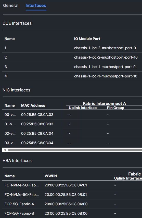
Step 3. From FlexPod-IMM-VMware/FlexPod-IMM-VMware, run the Setup_MDS.yml Ansible playbook.
ansible-playbook ./Setup_MDS.yml -i inventory
Step 4. When the Ansible playbook has been run and configured both switches, it is important to configure the local time so that logging time alignment and any backup schedules are correct. For more information on configuring the timezone and daylight savings time or summertime, see the Cisco MDS 9000 Series Fundamentals Configuration Guide, Release 9.x. Sample clock commands for the United States Eastern timezone are:
clock timezone EST -5 0
clock summer-time EDT 2 Sunday March 02:00 1 Sunday November 02:00 60
copy running-config startup-config
Step 5. SSH into each switch and execute the following commands.
clock timezone <timezone> <hour-offset> <minute-offset>
clock summer-time <timezone> <start-week> <start-day> <start-month> <start-time> <end-week> <end-day> <end-month> <end-time> <offset-minutes>
copy running-config startup-config
Step 6. Smart licensing should be setup in the MDS switches. For more information see: Cisco MDS 9000 Series Licensing Guide, Release 9.x.
Storage Configuration – ONTAP Boot Storage Setup
This chapter contains the following:
● Ansible ONTAP Storage Configuration Part 2
This configuration requires information from the Cisco UCS server profiles and NetApp storage system. After creating the boot LUNs, initiator groups, and appropriate mappings between the two, Cisco UCS server profiles will be able to see the boot disks hosted on NetApp controllers.
Ansible ONTAP Storage Configuration Part 2
Procedure 1. Obtain the WWPNs for UCS Server Profiles (required only for FC configuration)
Step 1. This was done in the previous section (FlexPod Cisco MDS Base).
Procedure 2. Obtain the IQNs for UCS Server Profiles (required only for iSCSI configuration)
Step 1. From the UCS Intersight account page, go to Infrastructure Service > Configure > Profiles > UCS Server Profiles > Profile > General > Configuration > Identifiers. The required IQN can be found to the right of IQN.
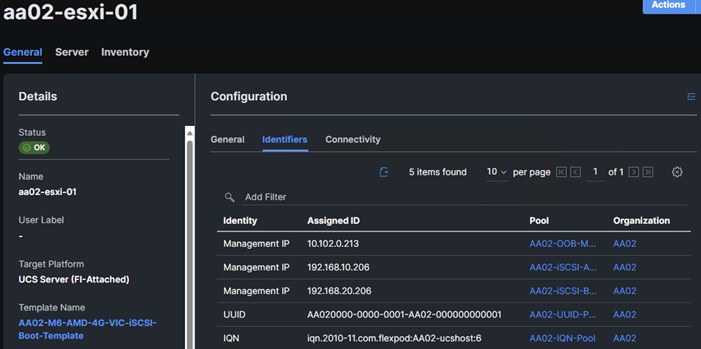
Procedure 3. Configure ONTAP Boot Storage using Ansible
Step 1. Edit the following variable files to ensure the proper ONTAP Boot Storage variables are entered:
● FlexPod-IMM-VMware/FlexPod-IMM-VMware/group_vars/all.yml
● FlexPod-IMM-VMware/FlexPod-IMM-VMware/vars/ontap_main.yml
Step 2. Update the boot_luns_iscsi and boot_luns_fcp variables under vars/ontap_main.yml file for ISCSi and FCP boot storage configuration. Update the initiator IQNs and WWPNs related variables in group_vars/all.yml file. Initiator IQNs and WWPNs are for ISCSi and FCP igroups.
Step 3. From FlexPod-IMM-VMware/FlexPod-IMM-VMware, invoke the ansible scripts for this section using the following command:
ansible-playbook -i inventory Setup_ONTAP.yml -t ontap_config_part_2
This chapter contains the following:
● Download ESXi 8.0 from VMware
● Cisco Intersight-based VMware ESXi 8.0 Install
● Access Cisco Intersight and Launch KVM
● Set up VMware ESXi Installation
● Set up Management Networking for ESXi Hosts
● FlexPod VMware ESXi Ansible Configuration
● vCenter and ESXi Ansible Setup
This section provides detailed instructions for installing VMware ESXi 8.0 in a FlexPod environment. On successful completion of these steps, multiple ESXi hosts will be provisioned and ready to be added to VMware vCenter.
Several methods exist for installing ESXi in a VMware environment. These procedures focus on how to use the built-in keyboard, video, mouse (KVM) console and virtual media features in Cisco Intersight to map remote installation media to individual servers.
Procedure 1. Download VMware ESXi ISO
Step 1. Click the following link: Cisco Custom Image for ESXi 8.0 Install CD.
Note: You will need a VMware user id and password on vmware.com to download this software.
Step 2. Download the .iso file.
Cisco Intersight-based VMware ESXi 8.0 Install
VMware ESXi 8.0 can now be installed and initially configured using Cisco Intersight. This feature requires the Intersight Advantage license to be installed and in use. The Intersight-based OS install makes use of the latest release of the Cisco UCS Server Configuration Utility (SCU).
Procedure 2. Download Cisco UCS SCU
Step 1. Click the following link: Cisco UCS SCU 6.3(2a).
Note: You will need a Cisco id and password to download this software.
Step 2. Download the .iso file.
Step 3. Place both the downloaded SCU ISO and the downloaded Cisco Custom Image for ESXi 8.0 ISO downloaded above on an https server.
Note: It is critical that these files are placed on an https (not http) server for the OS installation to complete. These files can also be placed on a CIFS or NFS server if that is more convenient. This procedure assumes use of https, but CIFS or NFS are supported and can also be used. In Cisco Intersight, go to System > Software Repository > SCU Links and click Add SCU Link.
Step 4. Select the correct Organization (for example, AA02) and HTTP/S. Input the File Location URL using https://. Click Next.
Step 5. Provide a Name for the SCU link (for example, UCS-SCU-6.3.2a), a Version (for example, 6.3(2a), and Supported Models (for example, ALL). Click Add.
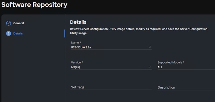
Step 6. In Cisco Intersight, go to System > Software Repository > OS Image Links and click Add OS Image Link.
Step 7. Select the correct Organization (for example, AA02) and HTTP/S. Input the File Location URL using https://. Click Next.
Step 8. Provide a Name for the OS Image link (for example, ESXi 8.0 Cisco Custom), a Vendor (for example, VMware), and a Version (for example, ESXi 8.0). Click Add.
Step 9. In Cisco Intersight, go to Infrastructure Service > Servers. On the left, select the checkbox next to each server that will have VMware ESXi 8.0 installed. At the top of bottom of the list, click … and select Install Operating System.
Step 10. Under General, the servers should already be selected. Select the checkboxes to install ESXi 8.0 on any other servers. Click Next.
Step 11. Select the radio button for the ESXi 8.0 Cisco Custom OS Image Link added above. Click Next.
Step 12. Leave Cisco selected as the Configuration Source. For each server, fill in all required fields. Click Next.
Note: Since the IB-MGMT VLAN was configured as the native VLAN for the vSwitch0 vNICs, it is not necessary to fill in a VLAN ID.
Step 13. Click Continue on the warning about Secure Boot.
Step 14. Select the radio button for the SCU Link added above. Click Next.
Step 15. For each server, select the boot protocol (Fibre Channel or iSCSI), then fill in the appropriate information, including LUN ID 0. Click Next.
Note: For Fibre Channel boot, the Initiator WWPN can be obtained by opening a duplicate tab of the web browser window for Intersight and selecting Servers. Click the Server Name link. Click Inventory > Network Adapters > <Adapter> > Interfaces > vHBA Interfaces. Copy the WWPN to the right of FCP-Fabric-A. The Target WWPN can be obtained by connecting to the storage cluster with ssh and typing “network interface show -vserver <Infra-SVM name>”. Copy the WWPN for LIF fcp-lif-01a.
Note: For iSCSI boot, the VNIC MAC address can be obtained by opening a duplicate tab of the web browser window for Intersight and selecting Servers. Click the Server Name link. Click Inventory > Network Adapters > <Adapter> > Interfaces > NIC Interfaces. Copy the MAC Address to the right of 04-iSCSI-A. The iSCSI Target IQN can be obtained by connecting to the storage cluster with ssh and typing “iscsi show -vserver <Infra-SVM name>”.
Step 16. Review all of the relevant information and click Install then click Install again to begin the OS Installation. The installation can take up to 45 minutes. The installation can be monitored using the Requests pane.
Step 17. When the OS Installation completes, you can skip down to (Optional) Reset VMware ESXi Host VMkernel Port MAC Address.
Access Cisco Intersight and Launch KVM
If Intersight Managed OS installation is not used, the Cisco Intersight vKVM enables the administrators to begin the installation of the operating system (OS) through a vMedia connection to the Cisco Custom ISO.
Procedure 1. Log into Intersight and Launch KVM
In this procedure, the KVM-mapped Cisco Custom ISO can be used to mount the Cisco Custom ISO and install VMware ESXi.
Step 1. Log into Cisco Intersight.
Step 2. Go to Infrastructure Service > Servers > <Server>.
Step 4. Launch vKVM consoles for all servers being provisioned.
Step 5. In each vKVM console, select Virtual Media > vKVM-Mapped DVD. Click Browse and browse to the downloaded VMware ESXi 8.0 Cisco Custom ISO. Click Open. Click Map Drive.
Step 1. In each vKVM console, go to Power > Reset System and click Confirm.
Set up VMware ESXi Installation
Procedure 1. Prepare the Server for the OS Installation
Note: Follow this step on each ESXi host.
Step 1. Monitor the server boot process in the vKVM. The server should find the boot LUNs and begin to load the ESXi installer.
Note: If the ESXi installer fails to load because the software certificates cannot be validated, reset the server, and when prompted, press F2 to go into BIOS and set the system time and date to current. The ESXi installer should load properly.
Procedure 1. Install VMware ESXi onto the bootable LUN of the UCS Servers
Note: Follow these steps on each host.
Step 1. After the ESXi installer is finished loading (from the last step), press Enter to continue with the installation.
Step 2. Read and accept the end-user license agreement (EULA). Press F11 to accept and continue.
Note: It may be necessary to map function keys as User Defined Macros under the Macros menu in the KVM console.
Step 3. Select the NetApp boot LUN that was previously set up as the installation disk for ESXi and press Enter to continue with the installation.
Step 4. Select the appropriate keyboard layout and press Enter.
Step 5. Enter and confirm the root password and press Enter.
Step 6. The installer issues a warning that the selected disk will be repartitioned. Press F11 to continue with the installation.
Step 7. After the installation is complete, press Enter to reboot the server.
Set up Management Networking for ESXi Hosts
Procedure 1. Add the Management Network for each VMware Host
Note: This is required for managing the host. To configure ESXi host with access to the management network, follow these steps on each ESXi host.
Step 1. After the server has finished rebooting, in the UCS KVM console, press F2 to customize VMware ESXi.
Step 2. Log in as root, enter the password set during installation, and press Enter to log in.
Step 3. Use the down arrow key to select Troubleshooting Options and press Enter.
Step 4. Select Enable ESXi Shell and press Enter.
Step 5. Select Enable SSH and press Enter.
Step 6. Press Esc to exit the Troubleshooting Options menu.
Step 7. Select the Configure Management Network option and press Enter.
Step 8. Select Network Adapters and press Enter. Ensure the vmnic numbers align with the numbers under the Hardware Label (for example, vmnic0 and 00-vSwitch0-A). If these numbers do not align, note which vmnics are assigned to which vNICs (indicated under Hardware Label).
Note: In previous FlexPod CVDs, vmnic1 was selected at this stage as the second adapter in vSwitch0. It is important not to select vmnic1 at this stage. If using the Ansible configuration and vmnic1 is selected here, the Ansible playbook will fail.
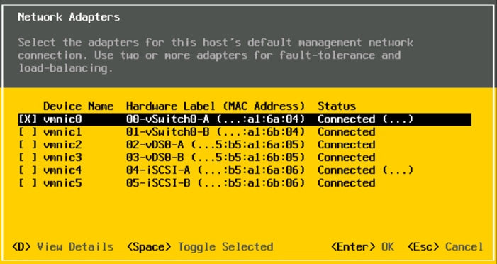
Step 9. Press Enter.
Note: In the UCS Configuration portion of this document, the IB-MGMT VLAN was set as the native VLAN on the 00-vSwitch0-A and 01-vSwitch0-B vNICs. Because of this, the IB-MGMT VLAN should not be set here and should remain Not set.
Step 10. Select IPv4 Configuration and press Enter.
Note: When using DHCP to set the ESXi host networking configuration, setting up a manual IP address is not required.
Step 11. Select the Set static IPv4 address and network configuration option by using the arrow keys and space bar.
Step 12. Under IPv4 Address, enter the IP address for managing the ESXi host.
Step 13. Under Subnet Mask, enter the subnet mask.
Step 14. Under Default Gateway, enter the default gateway.
Step 15. Press Enter to accept the changes to the IP configuration.
Note: In previous versions of this CVD, IPv6 was disabled at this point. That is no longer necessary as the Ansible scripts will disable IPv6.
Step 16. Select the DNS Configuration option and press Enter.
Note: If the IP address is configured manually, the DNS information must be provided.
Step 17. Using the spacebar, select Use the following DNS server addresses and hostname.
Step 18. Under Primary DNS Server, enter the IP address of the primary DNS server.
Step 19. Optional: Under Alternate DNS Server, enter the IP address of the secondary DNS server.
Step 20. Under Hostname, enter the fully qualified domain name (FQDN) for the ESXi host.
Step 21. Press Enter to accept the changes to the DNS configuration.
Step 22. Press Esc to exit the Configure Management Network submenu.
Step 23. Press Y to confirm the changes and restart the management network.
Step 24. Back in the System Customization menu, use the arrow keys to select Test Management Network and press Enter.
Step 25. Press Enter to run the test.
Step 26. It is normal the first time the test is run for the first ping to fail. The test can be run again to see all fields pass, or if the remaining fields pass, press Enter.
Step 27. Press Esc to exit the System Customization menu.
Step 28. Repeat this procedure for all installed ESXi hosts.
(Optional) Reset VMware ESXi Host VMkernel Port MAC Address
Procedure 1. (Optional) Reset VMware ESXi Host VMkernel Port MAC Address
Note: By default, the MAC address of the management VMkernel port vmk0 is the same as the MAC address of the Ethernet port it is placed on. If the ESXi host’s boot LUN is remapped to a different server Service Profile with different MAC addresses, a MAC address conflict will exist because vmk0 will retain the assigned MAC address unless the ESXi System Configuration is reset.
Step 1. From the ESXi console menu main screen, select Macros > Static Macros > Ctrl + Alt + F > Ctrl + Alt + F1 to access the VMware console command line interface.
Step 2. Log in as root.
Step 3. Type “esxcfg-vmknic –l” to get a detailed listing of interface vmk0. vmk0 should be a part of the “Management Network” port group. Note the IP address and netmask of vmk0.
Step 4. To remove vmk0, type esxcfg-vmknic –d “Management Network”.
Step 5. To re-add vmk0 with a random MAC address, type esxcfg-vmknic –a –i <vmk0-ip> -n <vmk0-netmask> “Management Network”.
Step 6. Verify vmk0 has been re-added with a random MAC address by typing esxcfg-vmknic –l.
Step 7. Tag vmk0 as the management interface by typing esxcli network ip interface tag add -i vmk0 -t Management.
Step 8. When vmk0 was re-added, if a message pops up saying vmk1 was marked as the management interface, type esxcli network ip interface tag remove -i vmk1 -t Management.
Step 9. Press Ctrl-D to log out of the ESXi console.
Step 10. Select Macros > Static Macros > Ctrl + Alt + F’s > Ctrl + Alt + F2 to return to the VMware ESXi menu.
Cisco Intersight Hardware Compatibility List (HCL) Status
Cisco Intersight evaluates the compatibility of your UCS system to check if the hardware and software have been tested and validated by Cisco or Cisco partners. Intersight reports validation issues after checking the compatibility of the server model, processor, firmware, adapters, operating system, and drivers, and displays the compliance status with the Hardware Compatibility List (HCL).
To determine HCL compatibility for VMware ESXi, Cisco Intersight uses Cisco UCS Tools. The Cisco UCS Tools is part of VMware ESXi Cisco custom ISO, and no additional configuration is required.
For more details on Cisco UCS Tools manual deployment and troubleshooting, go to: https://intersight.com/help/saas/resources/cisco_ucs_tools#about_cisco_ucs_tools
Procedure 1. View Compute Node Hardware Compatibility
Step 1. To find detailed information about the hardware compatibility of a compute node, in Cisco Intersight, click Infrastructure Service > Operate > Servers, click a server and select HCL.
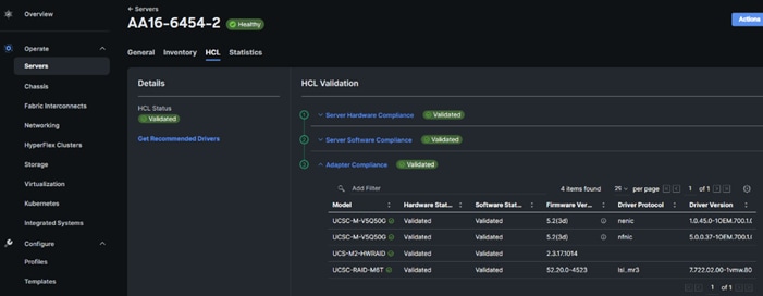
Step 2. If any of the drivers do not show Validated under Software Status, use this information to properly fill in the FlexPod-IMM-VMware/FlexPod-IMM-VMware/roles/VMware/ESXIhosts/defaults/main.yml file below.
FlexPod VMware ESXi Ansible Configuration
Procedure 1. Use Ansible to Configure All VMware ESXi Hosts from the Management Workstation
Step 1. Edit the following variable files to ensure proper VMware variables are entered:
● FlexPod-IMM-VMware/FlexPod-IMM-VMware/group_vars/secrets.yml
● FlexPod-IMM-VMware/FlexPod-IMM-VMware/inventory
● FlexPod-IMM-VMware/FlexPod-IMM-VMware/group_vars/all.yml
● FlexPod-IMM-VMware/FlexPod-IMM-VMware/roles/VMware/ESXIhosts/defaults/main.yml
● FlexPod-IMM-VMware/FlexPod-IMM-VMware/roles/VMware/ESXIiscsi/defaults/main.yml (If using iSCSI boot)
Step 2. From FlexPod-IMM-VMware/FlexPod-IMM-VMware, run the Setup_ESXi.yml Ansible playbook:
ansible-playbook ./Setup_ESXi.yml -i inventory
The procedures in the following sections provide detailed instructions for installing the VMware vCenter 7.0U3h Server Appliance in a FlexPod environment.
Procedure 1. Download vCenter 8.0 from VMware
Step 1. Click this link: https://customerconnect.vmware.com/downloads/details?downloadGroup=VC800C&productId=1345&rPId=108068 and download the VMware-VCSA-all-8.0.0-21457384.iso.
Note: You will need a VMware user id and password on vmware.com to download this software.
Procedure 4. Install the VMware vCenter Server Appliance
Note: The VCSA deployment consists of 2 stages: installation and configuration.
Step 1. Locate and copy the VMware-VCSA-all-8.0.0-21457384.iso file to the desktop of the management workstation. This ISO is for the VMware vSphere 8.0 vCenter Server Appliance.
Step 2. Mount the ISO image as a disk on the management workstation. For example, with the Mount command in Windows Server 2012 and above.
Step 3. In the mounted disk directory, navigate to the vcsa-ui-installer > win32 directory and double-click installer.exe. The vCenter Server Appliance Installer wizard appears.
Step 4. Click Install to start the vCenter Server Appliance deployment wizard.
Step 5. Click NEXT in the Introduction section.
Step 6. Read and accept the license agreement and click NEXT.
Step 7. In the “vCenter Server deployment target” window, enter the FQDN or IP address of the destination host, User name (root) and Password. Click NEXT.
Note: Installation of vCenter on a separate existing management infrastructure vCenter is recommended. If a separate management infrastructure is not available, customers can choose the recently configured first ESXi host as an installation target. The recently configured ESXi host is used in this deployment.
Step 8. Click YES to accept the certificate.
Step 9. Enter the Appliance VM name and password details shown in the Set up vCenter Server VM section. Click NEXT.
Step 10. In the Select deployment size section, select the Deployment size and Storage size. For example, select “Small” and “Default.” Click NEXT.
Step 11. Select the datastore (for example, infra_datastore) for storage. Click NEXT.
Step 12. In the Network Settings section, configure the following settings:
a. Select a Network: (for example, IB-MGMT Network)
Note: When the vCenter is running on the FlexPod, it is important that the vCenter VM stays on the IB-MGMT Network on vSwitch0 and not moved to a vDS. If vCenter is moved to a vDS and the virtual environment is completely shut down and then brought back up, trying to bring up vCenter on a different host than the one it was running on before the shutdown will cause problems with the network connectivity. With the vDS, for a virtual machine to move from one host to another, vCenter must be up and running to coordinate the move of the virtual ports on the vDS. If vCenter is down, the port move on the vDS cannot occur correctly. Moving vCenter to a different host on vSwitch0 does not require vCenter to already be up and running. If this vCenter is running in a different management environment, it is fine to have its’ networking on a vDS.
b. IP version: IPV4
c. IP assignment: static
d. FQDN: <vcenter-fqdn>
e. IP address: <vcenter-ip>
f. Subnet mask or prefix length: <vcenter-subnet-mask>
g. Default gateway: <vcenter-gateway>
h. DNS Servers: <dns-server1>,<dns-server2>
Step 13. Click NEXT.
Step 14. Review all values and click FINISH to complete the installation.
Note: The vCenter Server appliance installation will take a few minutes to complete.
Step 15. When Stage 1, Deploy vCenter Server, is complete, click CONTINUE to proceed with stage 2.
Step 16. Click NEXT.
Step 17. In the vCenter Server configuration window, configure these settings:
a. Time Synchronization Mode: Synchronize time with NTP servers.
b. NTP Servers: NTP server IP addresses from IB-MGMT VLAN
c. SSH access: Activated.
Step 18. Click NEXT.
Step 19. Complete the SSO configuration as shown below (or according to your organization’s security policies):
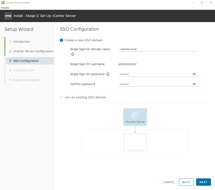
Step 20. Click NEXT.
Step 21. Decide whether to join VMware’s Customer Experience Improvement Program (CEIP).
Step 22. Click NEXT.
Step 23. Review the configuration and click FINISH.
Step 24. Click OK.
Note: vCenter Server setup will take a few minutes to complete and Install – Stage 2 with show Complete.
Step 25. Click CLOSE. Eject or unmount the VCSA installer ISO.
Procedure 5. Verify vCenter CPU Settings
Note: If a vCenter deployment size of Small or larger was selected in the vCenter setup, it is possible that the VCSA’s CPU setup does not match the Cisco UCS server CPU hardware configuration. Cisco UCS C-Series M6 and B200 M6 servers are 2-socket servers. During this validation, the Small deployment size was selected and vCenter was setup for a 4-socket server. This setup can cause issues in the VMware ESXi cluster Admission Control.
Step 1. Open a web browser on the management workstation and navigate to the vCenter or ESXi server where the vCenter appliance was deployed and login.
Step 2. Click the vCenter VM, right-click and select Edit settings.
Step 3. In the Edit settings window, expand CPU and check the value of Sockets.
Step 4. If the number of Sockets matches the server configuration, click Cancel.
Step 5. If the number of Sockets does not match the server configuration, it will need to be adjusted:
a. Right-click the vCenter VM and click Guest OS > Shut down. Click Yes on the confirmation.
b. When vCenter is shut down, right-click the vCenter VM and click Edit settings.
c. In the Edit settings window, expand CPU and change the Cores per Socket value to make the Sockets value equal to the server configuration.
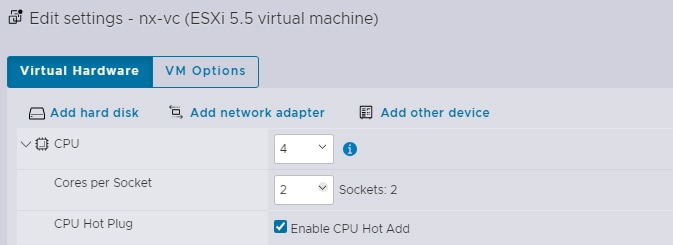
Step 6. Click SAVE.
Step 7. Right-click the vCenter VM and click Power > Power on. Wait approximately 10 minutes for vCenter to come up.
Procedure 6. Setup VMware vCenter Server
Step 1. Using a web browser, navigate to https://<vcenter-ip-address>:5480. Navigate the security screens.
Step 2. Log into the VMware vCenter Server Management interface as root with the root password set in the vCenter installation.
Step 3. In the menu on the left, click Time.
Step 4. Click EDIT to the right of Time zone.
Step 5. Select the appropriate Time zone and click SAVE.
Step 6. In the menu on the left select Administration.
Step 7. According to your Security Policy, adjust the settings for the root user and password.
Step 8. In the menu on the left click Update.
Step 9. Follow the prompts to stage and install any available vCenter 8.0 (not 8.0U1) updates.
Step 10. In the upper right-hand corner of the screen, click root > Logout to logout of the Appliance Management interface.
Step 11. Using a web browser, navigate to https://<vcenter-fqdn> and navigate through security screens.
Note: With VMware vCenter 7.0 and above, you must use the vCenter FQDN.
Step 12. Select LAUNCH VSPHERE CLIENT.
Step 13. Log in using the Single Sign-On username (administrator@vsphere.local) and password created during the vCenter installation. Dismiss the Licensing warning.
Procedure 7. Add AD User Authentication to vCenter (Optional)
Step 1. In the AD Infrastructure, using the Active Directory Users and Computers tool, setup a Domain Administrator user with a user name such as flexadmin (FlexPod Admin).
Step 2. Connect to https://<vcenter-fqdn> and select LAUNCH VSPHERE CLIENT.
Step 3. Log in as administrator@vsphere.local (or the SSO user set up in vCenter installation) with the corresponding password.
Step 4. Under the top-level menu, click Administration. In the list on the left, under Single Sign On, select Configuration.
Step 5. In the center pane, under Configuration, select the Identity Provider tab.
Step 6. In the list under Type, select Active Directory Domain.
Step 7. Click JOIN AD.
Step 8. Fill in the AD domain name, the Administrator user, and the domain Administrator password. Do not fill in an Organizational unit. Click JOIN.
Step 9. Click Acknowledge.
Step 10. In the list on the left under Deployment, click System Configuration. Select the radio button to select the vCenter, then click REBOOT NODE.
Step 11. Input a reboot reason and click REBOOT. The reboot will take approximately 10 minutes for full vCenter initialization.
Step 12. Log back into the vCenter vSphere Client as Administrator@vsphere.local.
Step 13. Under the top-level menu, click Administration. In the list on the left, under Single Sign On, click Configuration.
Step 14. In the center pane, under Configuration, click the Identity Provider tab. Under Type, select Identity Sources. Click ADD.
Step 15. Make sure Active Directory (Integrated Windows Authentication) is selected, your Windows Domain name is listed, and Use machine account is selected. Click ADD.
Step 16. In the list select the Active Directory (Integrated Windows Authentication) Identity source type. If desired, select SET AS DEFAULT and click OK.
Step 17. Under Access Control, select Global Permissions.
Step 18. In the center pane, click ADD to add a Global Permission.
Step 19. In the Add Permission window, select your AD domain for the Domain.
Step 20. In the User/Group line, enter either the FlexPod Admin username or the Domain Admins group. Leave the Role set to Administrator. Check the box for Propagate to children.
Note: The FlexPod Admin user was created in the Domain Admins group. The selection here depends on whether the FlexPod Admin user will be the only user used in this FlexPod or if additional users will be added later. By selecting the Domain Admins group, any user placed in that AD Domain group will be able to login to vCenter as an Administrator.
Step 21. Click OK to add the selected User or Group. The user or group should now appear in the Global Permissions list with the Administrator role.
Step 22. Log out and log back into the vCenter HTML5 Client as the FlexPod Admin user. You will need to add the domain name to the user, for example, flexadmin@domain if you did not make your AD Domain the default domain.
vCenter and ESXi Ansible Setup
Procedure 1. Configure the VMware vCenter and the three management ESXi hosts
Step 1. Edit the following variable files to ensure proper VMware variables are entered:
● FlexPod-IMM-VMware/FlexPod-IMM-VMware/group_vars/secrets.yml
● FlexPod-IMM-VMware/FlexPod-IMM-VMware/inventory
● FlexPod-IMM-VMware/FlexPod-IMM-VMware/group_vars/all.yml
● FlexPod-IMM-VMware/FlexPod-IMM-VMware/roles/VMware/ESXIpostvC/defaults/main.yml
● FlexPod-IMM-VMware/FlexPod-IMM-VMware/roles/VMware/ESXIpostvCiscsi/defaults/main.yml
Step 2. From FlexPod-IMM-VMware/FlexPod-IMM-VMware, run the Setup_vCenter.yml Ansible playbook:
ansible-playbook ./Setup_vCenter.yml -i inventory
Note: After the playbook run is complete, complete the following manual steps to complete vCenter setup.
Step 3. Right-click the Cluster that was created and select Settings.
Step 4. In the list in the center pane under Configuration, select General.
Step 5. On the right, to the right of General, select EDIT.
Step 6. Select Datastore specified by host and click OK.
Step 7. In the list on the left, select the first ESXi host. In the center pane, select the Configure tab.
Step 8. In the center pane list under Virtual Machines, click Swap File location.
Step 9. On the right, click EDIT.
Step 10. Select infra_swap and click OK.
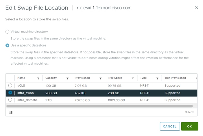
Step 11. Repeat steps 7-10 to set the swap file location for each ESXi host.
Step 12. Select each ESXi host and from the Summary tab, clear any alerts or alarms associated with the host.
Step 13. Select the first ESXi host and under Configure > System, click Power Management. In the upper right corner, click EDIT. Fill in the User name (admin or flexadmin) and associated password as configured in the Local User policy. The MAC can also be obtained by using ipmitool on a Linux machine with the following query: “ipmitool -I lanplus -H <serverOOBMGMTIP> -U flexadmin -P <password> lan print”. The server’s <serverOOBMGMTIP> can be obtained in Cisco Intersight under Infrastructure Service > Servers. When all fields are populated, click OK. VMware ESXi will launch an IPMI over LAN query to the server’s CIMC and verify the BMC MAC address. This setup will allow the ESXi host to be powered on from vCenter. Repeat this step for all ESXi hosts.
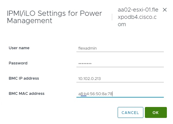
Note: IPMI over LAN cannot be configured for Cisco UCS C220 and C240 M7 servers.
Step 14. Optional. This step is optional and should only be done if you are not using Cisco Intersight Workload Optimizer (IWO) to suspend servers in an effort to lower power usage. In VMware vCenter, under Inventory, select the ESXi cluster. In the center pane, select Configure and then under Services select vSphere DRS. On the right, click EDIT then select Power Management. Check the Enable box to turn on DPM and select your desired Automation Level. Click OK to finalize this setting.
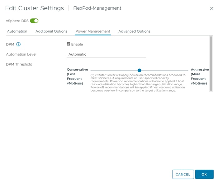
Note: It is recommended to cycle through the ESXi hosts testing whether the server can be powered on with IPMI over LAN before turning on DPM.
Step 15. Select the first ESXi host. In the center pane under Configure > Storage, click Storage Devices. Make sure the NETAPP Fibre Channel Disk LUN 0 or NETAPP iSCSI Disk LUN 0 is selected.
Step 16. Click the Paths tab.
Step 17. Ensure that 4 paths appear, two of which should have the status Active (I/O). The output below shows the paths for an iSCSI LUN.
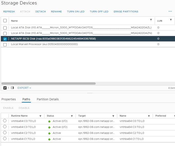
Step 18. Repeat steps 15-17 for all ESXi hosts.
Procedure 8. VMware ESXi 8.0 TPM Attestation
Note: If your Cisco UCS servers have Trusted Platform Module (TPM) 2.0 modules installed, the TPM can provide assurance that ESXi has booted with UEFI Secure Boot enabled and using only digitally signed code. In the Cisco UCS Configuration section of this document, UEFI secure boot was enabled in the boot order policy. A server can boot with UEFI Secure Boot with or without a TPM 2.0 module. If it has a TPM, VMware vCenter can attest that the server booted with UEFI Secure Boot.
Step 1. For Cisco UCS servers that have TPM 2.0 modules installed, TPM Attestation can be verified in the vSphere HTML5 Client.
Step 2. In the vCenter Interface, under Inventory select the cluster.
Step 3. In the center pane, click the Monitor tab.
Step 4. Click Monitor > Security. The Attestation status will show the status of the TPM:
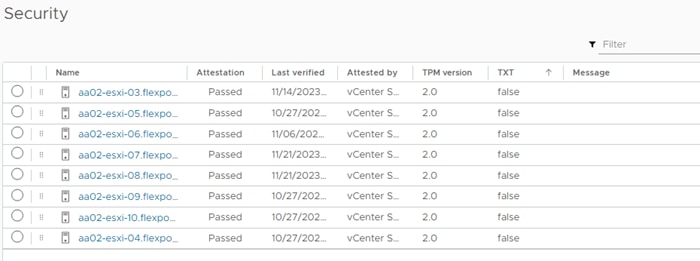
Note: It may be necessary to disconnect and reconnect or reboot a host from vCenter to get it to pass attestation the first time.
Procedure 9. Avoiding Boot Failure When UEFI Secure Booted Server Profiles are Moved
Typically, hosts in FlexPod Datacenter are configured for boot from SAN. Cisco UCS supports stateless compute where a server profile can be moved from one blade or compute node to another seamlessly.
When a server profile is moved from one blade to another blade server with the following conditions, the ESXi host runs into PSOD and ESXi will fail to boot:
● TPM present in the node (Cisco UCS M5 and M6 family servers)
● Host installed with ESXi 7.0 U2 or above
● Boot mode is UEFI Secure
● Error message: Unable to restore system configuration. A security violation was detected. https://via.vmw.com/security-violation.
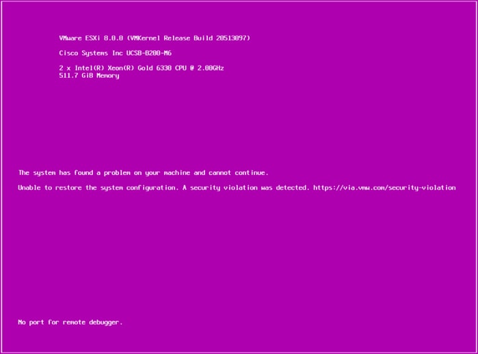
Step 1. Log into the host using SSH.
Step 2. Gather the recovery key using this command:
[root@nx-esxi-1:~] esxcli system settings encryption recovery list
Recovery ID Key
-------------------------------------- ---
{74AC4D68-FE47-491F-B529-6355D4AAF52C} 529012-402326-326163-088960-184364-097014-312164-590080-407316-660658-634787-601062-601426-263837-330828-197047
Step 3. Store the keys from all hosts in a safe location.
Step 4. After associating the Server Profile to the new compute-node or blade, stop the ESXi boot sequence by pressing Shift + O when the ESXi boot screen appears.
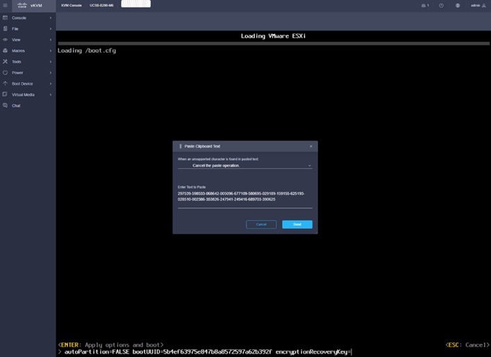
Step 5. Add the recovery key using following boot option: encryptionRecoveryKey=recovery_key. Use File > Paste Clipboard Text and Send to paste in the recovery key. Press Enter to continue the boot process.
Step 6. To persist the change, enter the following command at the VMware ESXi ssh command prompt:
/sbin/auto-backup.sh
Note: For more information, go to: https://docs.vmware.com/en/VMware-vSphere/8.0/vsphere-security/GUID-30DA8CC1-5D9F-4025-B5DB-6D592B6BD9B4.html.
Storage Configuration – ONTAP NVMe Configuration and Finalizing ONTAP Storage
This chapter contains the following:
● Ansible ONTAP Storage Configuration Part 3
Ansible ONTAP Storage Configuration Part 3
Procedure 1. Configure the ONTAP NVMe setup and finalize ONTAP storage using Ansible
Step 1. Edit the following variable files to ensure proper variables are entered:
● FlexPod-IMM-VMware/FlexPod-IMM-VMware/group_vars/all.yml
● FlexPod-IMM-VMware/FlexPod-IMM-VMware/vars/ontap_main.yml
Note: Update the “nvme_namespaces” and “nvme_subsystem” variables in vars/ontap_main.yml file. Add the NQNs from each ESXi host to the corresponding variable “nvme_nqn” in group_vars/all.yml file. The NVMe namespace will be shared by all the hosts in the nvme subsystem in this solution
Note: The ONTAP NVMe setup is only required for FC-NVMe and NVMe/TCP configurations.
Step 2. From FlexPod-IMM-VMware/FlexPod-IMM-VMware, invoke the ansible scripts for this section using the following command:
ansible-playbook -i inventory Setup_ONTAP.yml -t ontap_config_part_3
Procedure 10. Configure ESXi Host NVMe over FC and NVMe over TCP Datastore
Step 1. To verify that the NVMe Fibre Channel Disk is mounted on each ESXi host, log into the VMware vCenter using a web-browser.
Step 2. Under Inventory select an ESXi host running FC-NVMe. In the center pane, go to Configure > Storage > Storage Devices. The NVMe Fibre Channel Disk should be listed under Storage Devices.
Step 3. Select the NVMe Fibre Channel Disk, then select Paths underneath. Verify 2 paths have a status of Active (I/O) and 2 paths have a status of Active.
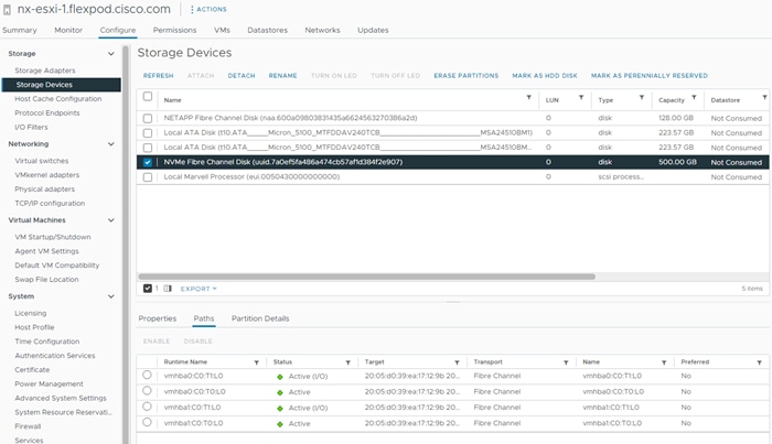
Step 4. Repeat Step 3 for all the FC-NVMe hosts.
Step 5. Under Inventory select an ESXi host running NVMe-TCP. In the center pane, go to Configure > Storage > Storage Adapters.
Step 6. Click ADD SOFTWARE-ADAPTER > Add NVMe over TCP adapter. From the drop-down list select vmnic4/nenic and click OK. A new vmhba should appear under Storage Adapters.
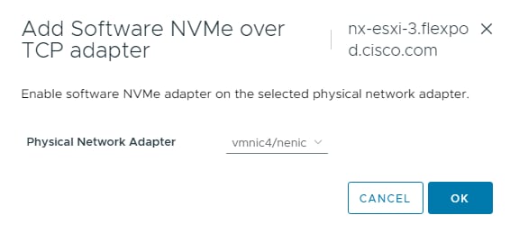
Step 7. Click ADD SOFTWARE-ADAPTER > Add NVMe over TCP adapter to add a second vmhba. Use the pulldown to select vmnic5/nenic and click OK. A new vmhba should appear under Storage Adapters.
Step 8. Select the first VMware NVMe over TCP Storage Adapter added (for example, vmhba65). In the middle of the window, select the Controllers tab. Click ADD CONTROLLER.
Step 9. Enter the IP address of nvme-tcp-lif-01a and click DISCOVER CONTROLLERS. Select the two controllers in the Infra-NVMe-TCP-A subnet and click OK. The two controllers should now appear under the Controllers tab after clicking Refresh.
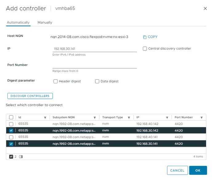
Step 10. Select the second VMware NVMe over TCP Storage Adapter added (for example, vmhba66). In the middle of the window, select the Controllers tab. Click ADD CONTROLLER.
Step 11. Enter the IP address of nvme-tcp-lif-02b and click DISCOVER CONTROLLERS. Select the two controllers in the Infra-NVMe-TCP-B subnet and click OK. The two controllers should now appear under the Controllers tab after clicking to Refresh.
Step 12. Repeat steps 5-11 for all ESXi hosts running NVMe-TCP.
Step 13. For each of the hosts running NVMe-TCP, select Configure > Storage > Storage Devices, then select the NVMe Disk. Under the Paths tab, make sure that 4 paths are shown and that 2 of the paths have the Status Active (I/O). Also, all paths should have the Transport TCPTRANSPORT.
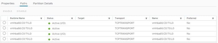
Step 14. For any one of these hosts, right-click the host under Inventory and click Storage > New Datastore. Leave VMFS selected and click NEXT.
Step 15. Name the datastore (for example, nvme_datastore) and select the NVMe Disk. Click NEXT.
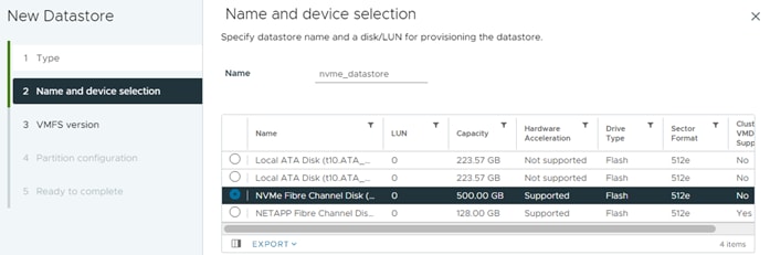
Step 16. Leave VMFS 6 selected and click NEXT.
Step 17. Leave all Partition configuration values at the default values and click NEXT.
Step 18. Review the information and click FINISH.
Step 19. Select Storage, expand the vCenter and Datacenter, and select the new NVMe datastore. In the center pane, select Hosts. Ensure all the NVMe hosts have mounted the datastore.
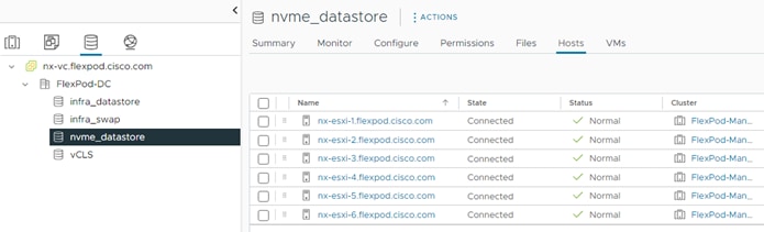
Note: If any hosts are missing from the list, it may be necessary to put the host in Maintenance Mode and reboot the host. If you happen to have hosts with both FC-boot and iSCSI-boot and are running both FC-NVMe and NVMe-TCP, notice that the same datastore is mounted on both types of hosts and that the only difference in the storage configuration is what LIF the traffic is coming in on.
FlexPod Management Tools Setup
This chapter contains the following:
● Cisco Intersight Hardware Compatibility List (HCL) Status
● NetApp ONTAP Tools 9.12 Deployment
● Provision Datastores using ONTAP Tools (Optional)
● Virtual Volumes – vVol (Optional)
● NetApp SnapCenter Plug-in 4.8 Installation
● NetApp SnapCenter 4.8 Configuration
● Active IQ Unified Manager 9.12 Installation
● Configure Active IQ Unified Manager
● Deploy Cisco Intersight Assist Appliance
● Claim VMware vCenter using Cisco Intersight Assist Appliance
● Claim NetApp Active IQ Manager using Cisco Intersight Assist Appliance
● Claim Cisco Nexus Switches using Cisco Intersight Assist Appliance
● Claim Cisco MDS Switches using Cisco Intersight Assist Appliance
● Create a FlexPod Integrated System
● Cisco Nexus Dashboard Fabric Controller (NDFC)–SAN
Cisco Intersight Hardware Compatibility List (HCL) Status
Cisco Intersight evaluates the compatibility of your UCS system to check if the hardware and software have been tested and validated by Cisco or Cisco partners. Intersight reports validation issues after checking the compatibility of the server model, processor, firmware, adapters, operating system, and drivers, and displays the compliance status with the Hardware Compatibility List (HCL).
To determine HCL compatibility for VMware ESXi, Cisco Intersight uses Cisco UCS Tools. The Cisco UCS Tools is part of VMware ESXi Cisco custom ISO, and no additional configuration is required.
For more information on Cisco UCS Tools manual deployment and troubleshooting, go to: https://intersight.com/help/saas/resources/cisco_ucs_tools#about_cisco_ucs_tools
NetApp ONTAP Tools 9.12 Deployment
The ONTAP tools for VMware vSphere provide end-to-end life cycle management for virtual machines in VMware environments that use NetApp storage systems. It simplifies storage and data management for VMware environments by enabling administrators to directly manage storage within the vCenter Server. This topic describes the deployment procedures for the NetApp ONTAP Tools for VMware vSphere.
NetApp ONTAP Tools for VMware vSphere 9.12 Pre-installation Considerations
The following licenses are required for ONTAP Tools on storage systems that run ONTAP 9.8 or above:
● Protocol licenses (NFS, FCP, and/or iSCSI)
● NetApp FlexClone ((optional) Required for performing test failover operations for SRA and for vVols operations of VASA Provider
● NetApp SnapRestore (for backup and recovery)
● The NetApp SnapManager Suite
● NetApp SnapMirror or NetApp SnapVault (Optional - required for performing failover operations for SRA and VASA Provider when using vVols replication)
The Backup and Recovery capability has been integrated with SnapCenter and requires additional licenses for SnapCenter to perform backup and recovery of virtual machines and applications.
Note: Beginning with ONTAP 9.10.1, all licenses are delivered as NLFs (NetApp License File). NLF licenses can enable one or more ONTAP features, depending on your purchase. ONTAP 9.10.1 also supports 28-character license keys using System Manager or the CLI. However, if an NLF license is installed for a feature, you cannot install a 28-character license key over the NLF license for the same feature.
Table 6. Port Requirements for NetApp ONTAP Tools
| TCP Port |
Requirement |
| 443 (HTTPS) |
Secure communications between VMware vCenter Server and the storage systems |
| 8143 (HTTPS) |
ONTAP Tools listens for secure communications |
| 9083 (HTTPS) |
VASA Provider uses this port to communicate with the vCenter Server and obtain TCP/IP settings |
| 7 |
ONTAP tools sends an echo request to ONTAP to verify reachability and is required only when adding storage system and can be disabled later. |
Note: The requirements for deploying NetApp ONTAP Tools are listed here.
Procedure 1. Install NetApp ONTAP Tools for VMware vSphere via Ansible
Step 1. Clone the repository from https://github.com/NetApp/ONTAP-Tools-for-VMware-vSphere.
Step 2. Follow the instructions in the README file in the repository to ensure the Ansible environment is configured properly.
Step 3. Update the following variable files:
hosts
group_vars/vcenter
vars/ontap_tools_main.yml
Step 4. To invoke the ansible scripts, use the following command:
ansible-playbook -i hosts Setup_ONTAP_tools.yml
Note: The above playbook installs NetApp ONTAP Tools for VMware vSphere and registers it with VMWare vCenter. It also adds the ONTAP Storage System to ONTAP tools.
Procedure 2. Install NetApp ONTAP Tools for VMware vSphere Manually
Use the following steps to manually install NetApp ONTAP Tools for VMware vSphere if desirable, or if there is a problem with running Ansible automation for it.
Step 1. Launch the vSphere Web Client and navigate to Hosts and Clusters.
Step 2. Select ACTIONS for the FlexPod-DC datacenter and select Deploy OVF Template.
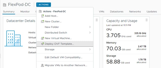
Step 3. Select an OVF template from remote URL or local file system and click NEXT.
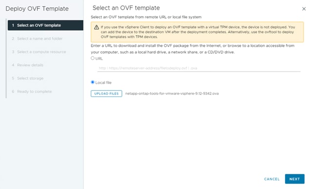
Step 4. Enter the VM name, select a location for the VM and click NEXT.
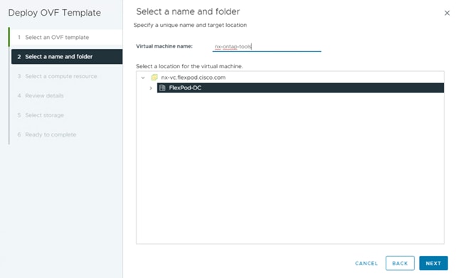
Step 5. Select a host cluster resource in which to deploy OVA and click NEXT.
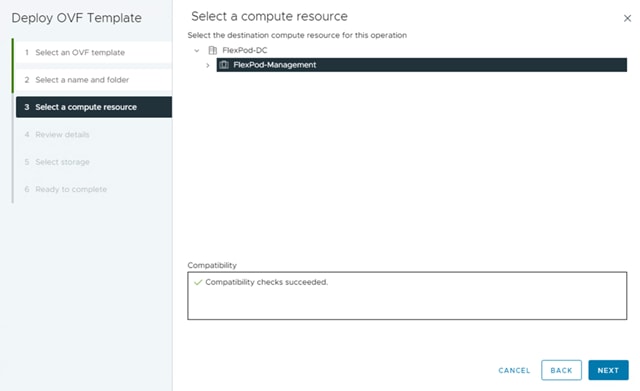
Step 6. Verify the template details and click Next.
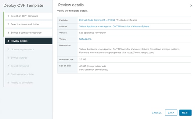
Step 7. Read and accept the license agreement and click Next.
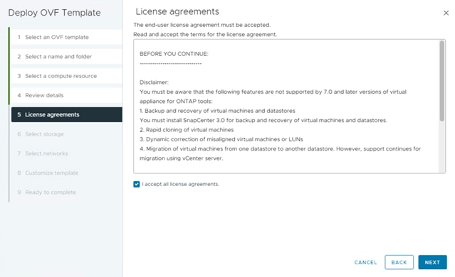
Step 8. Select the Thin Provision option for the virtual disk format, select infra_datastore for storage and click Next.
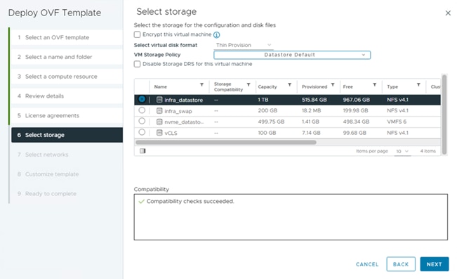
Step 9. Select a destination network, IP protocol, and click Next.
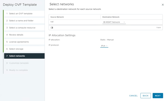
Step 10. From Customize Template, enter the ONTAP tools system configurations, vCenter name or IP address and other network property details and click NEXT.
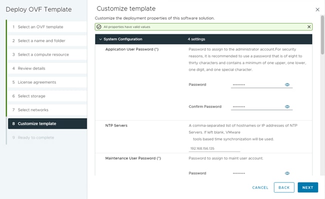
Step 11. Review the configuration details entered and click FINISH to complete the deployment of ONTAP tools VM.
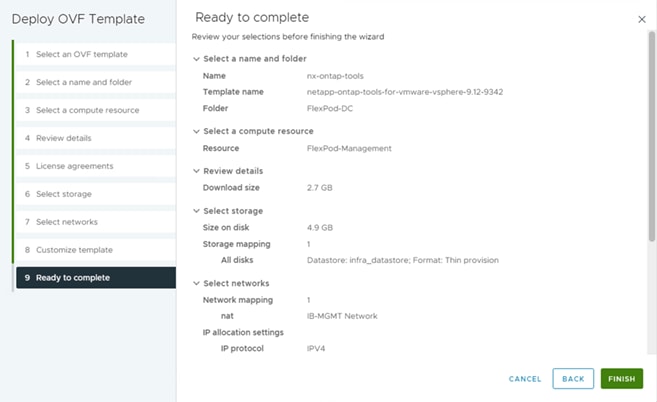
Step 12. Power on the ONTAP tools VM and open the VM console to monitor the boot up process and the information provided to confim that the tool is registered with vCenter and the Virtual Storage Console (VSC) is running.
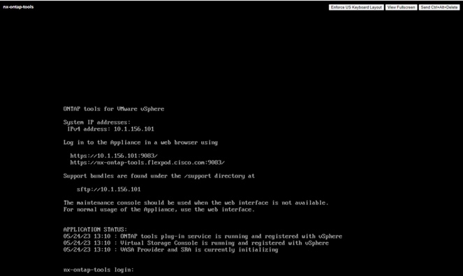
Note: If ONTAP tools is not registered with any vCenter Server, go to https://appliance_ip:8143/Register.html to register the VSC instance. The Register.html redirects you to the swagger page. From ONTAP tools 9.12 onwards the registration of ONTAP tools with vCenter happens from the swagger page.
Step 13. Click the notification on top of the vSphere Client GUI to see the notification that the ONTAP tools plugin has been deployed and click REFRESH BROWSER to enable it.
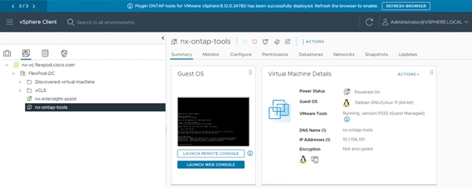
Step 14. From the vSphere Client GUI menu, open the NetApp ONTAP tools plugin to view the plugin information, add storage system, and provision datastores.
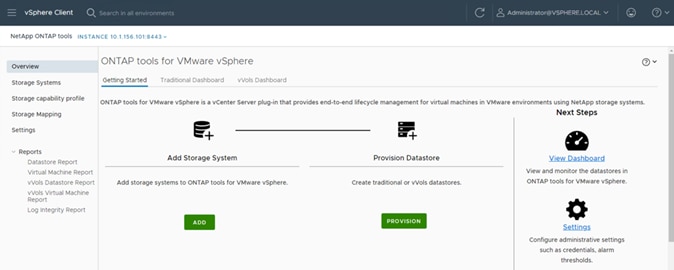
Procedure 3. Add ONTAP Cluster to ONTAP tools manually
Step 1. From the vSphere Client GUI Menu, open the NetApp ONTAP tools plugin.
Step 2. From the Getting Started tab, add storage system to ONTAP tools by clicking ADD.
Step 3. Provide the storage system information and login credential and click ADD.
Step 4. 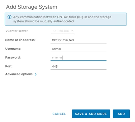
Step 5. Click YES when prompted to authorize the ONTAP Cluster certificate.
Step 6. Go to the Storage System menu to see the newly added ONTAP cluster information.
Procedure 4. Download and Install the NetApp NFS Plug-in for VMware VAAI
Step 1. Download the Netapp NFS Plug-in 2.0.1 for VMware VAAI file from: https://mysupport.netapp.com/site/products/all/details/nfsplugin-vmware-vaai/downloads-tab
Step 2. Go to vib20 > NetAppNasPlugin and unzip the file and extract NetApp_bootbank_NetAppNasPlugin_2.0.1-16.vib.
Step 3. Rename the .vib file to NetAppNasPlugin.vib to match the predefined name that ONTAP tools uses.
Step 4. Click Settings from the ONTAP tool Getting Started page.
Step 5. Click NFS VAAI Tools tab.
Step 6. Click Change in the Existing version section.
Step 7. Browse and select the renamed .vib file, and then click Upload to upload the file to the virtual appliance.
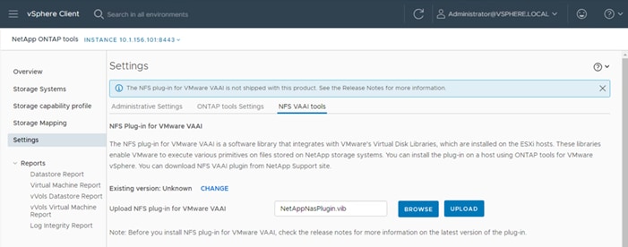
Note: The next step is only required on the hosts where NetApp VAAI plug-in was not installed alongside Cisco VIC driver installation.
Step 8. In the Install on ESXi Hosts section, select the ESXi host where the NFS Plug-in for VAAI is to be installed, and then click Install.
Step 9. Reboot the ESXi host after the installation finishes.
Procedure 11. Verify the VASA Provider
Note: The VASA provider for ONTAP is enabled by default during the installation of the NetApp ONTAP tools.
Step 1. From the vSphere Client, click Menu > NetApp ONTAP tools.
Step 2. Click Settings.
Step 3. From the Administrative Settings tab, click Manage Capabilities.
Step 4. In the Manage Capabilities dialog box, click Enable VASA Provider if it was not pre-enabled.
Step 5. Enter the IP address of the virtual appliance for ONTAP tools, VASA Provider, and VMware Storage Replication Adapter (SRA) and the administrator password, and then click Apply if changes to capabilities were made.
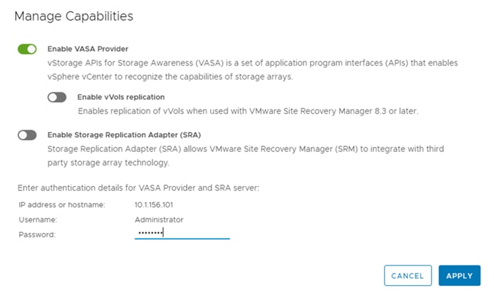
Procedure 5. Update Host and Storage Data
Step 1. From the vSphere Client Home Page, click Hosts and Clusters.
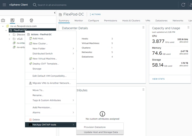
Step 3. On the Confirmation dialog box, click YES. It might take a few minutes to update the data.
Procedure 6. Optimal Storage Settings for ESXi Hosts
Note: ONTAP tools enables the automated configuration of storage-related settings for all ESXi hosts that are connected to NetApp storage controllers.
Step 1. From the VMware vSphere Web Client Home page, click vCenter > Hosts and Clusters.
Step 2. Select a host and then click Actions > NetApp ONTAP tools > Set Recommended Values.
Step 3. In the NetApp Recommended Settings dialog box, select all the applicable values for the ESXi host.
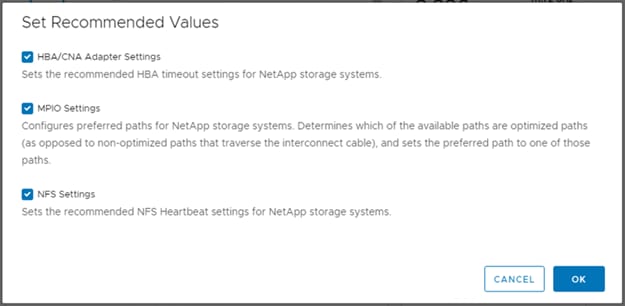
Note: This functionality sets values for HBAs and converged network adapters (CNAs), sets appropriate paths and path-selection plug-ins, and verifies appropriate settings for NFS I/O. A vSphere host reboot may be required after applying the settings.
Table 7. Click OK.
Provision Datastores using ONTAP Tools (Optional)
Using ONTAP tools, the administrator can provision an NFS, FC, FC-NVMe or iSCSI datastore and attach it to a single or multiple hosts in the cluster. The following steps describe provisioning a datastore and attaching it to the cluster.
Note: It is a NetApp best practice to use ONTAP tools to provision any additional datastores for the FlexPod infrastructure. When using VSC to create vSphere datastores, all NetApp storage best practices are implemented during volume creation and no additional configuration is needed to optimize performance of the datastore volumes.
Storage Capabilities
A storage capability is a set of storage system attributes that identifies a specific level of storage performance (storage service level), storage efficiency, and other capabilities such as encryption for the storage object that is associated with the storage capability.
Create the Storage Capability Profile
In order to leverage the automation features of VASA two primary components must first be configured. The Storage Capability Profile (SCP) and the VM Storage Policy. The Storage Capability Profile expresses a specific set of storage characteristics into one or more profiles used to provision a Virtual Machine. The SCP is specified as part of VM Storage Policy. NetApp ONTAP tools comes with several pre-configured SCPs such as Platinum, Bronze, and so on.
Note: The ONTAP tools for VMware vSphere plug-in also allows you to set Quality of Service (QoS) rule using a combination of maximum and/or minimum IOPs.
Procedure 1. Review or Edit the Built-In Profiles Pre-Configured with ONTAP Tools
Step 1. From the vCenter console, click Menu > NetApp ONTAP tools.
Step 2. From the NetApp ONTAP tools click Storage Capability Profiles.
Step 3. Select the Platinum Storage Capability Profile and select Clone from the toolbar.
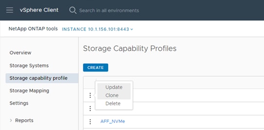
Step 4. Enter a name for the cloned SCP (for example, AFF_Platinum_Encrypted) and add a description if desired. Click NEXT.
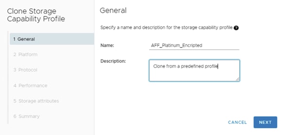
Step 5. Select All Flash FAS(AFF) for the storage platform and click NEXT.
Step 6. Select Any for the Protocol and click NEXT.
Step 7. Select None to allow unlimited performance or set a the desired minimum and maximum IOPS for the QoS policy group. Click NEXT.
Step 8. On the Storage attributes page, change the Encryption and Tiering policy to the desired settings and click NEXT. In the example below, Encryption was enabled.
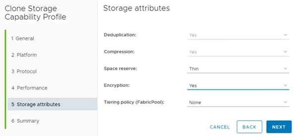
Step 9. Review the summary page and click FINISH to create the storage capability profile.
Note: It is recommended to Clone the Storage Capability Profile if you wish to make any changes to the predefined profiles rather than editing the built-in profile.
Procedure 7. Create a VM Storage Policy
Note: You must create a VM storage policy and associate SCP to the datastore that meets the requirements defined in the SCP.
Step 1. From the vCenter console, click Menu > Policies and Profiles.
Step 2. Select VM Storage Policies and click CREATE.
Step 3. Create a name for the VM storage policy and enter a description if desired and click NEXT.
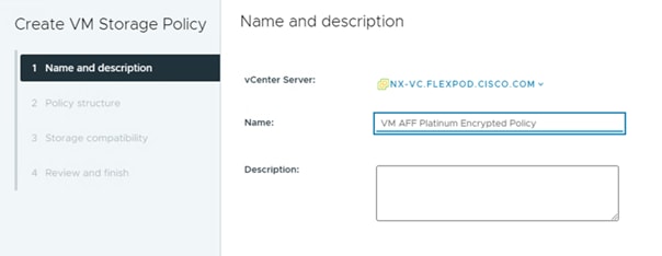
Step 4. Select Enable rules for NetApp.clustered.Data.ONTAP.VP.VASA10 storage located under the Datastore specific rules section and click NEXT.
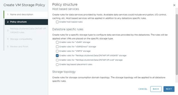
Step 5. From the Placement tab select the SCP created in the previous step and click NEXT.
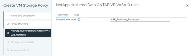
Step 6. All the datastores with matching capabilities are displayed, click NEXT.
Step 7. Review the policy summary and click FINISH.
Procedure 8. Provision NFS Datastore
Step 1. From the vCenter console, click Menu > NetApp ONTAP tools.
Step 2. From the ONTAP tools Home page, click Overview.
Step 3. From the Getting Started tab, click Provision.
Step 4. Click Browse to select the destination to provision the datastore.
Step 5. Select the type as NFS and Enter the datastore name (for example, NFS_DS_1).
Step 6. Provide the size of the datastore and the NFS Protocol.
Step 7. Check the storage capability profile and click NEXT.
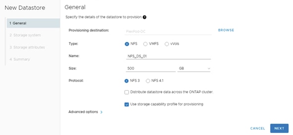
Step 8. Select the desired Storage Capability Profile, cluster name and the desired SVM to create the datastore. In this example, the Infra-SVM is selected.
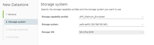
Step 9. Click NEXT.
Step 10. Select the aggregate name and click NEXT.
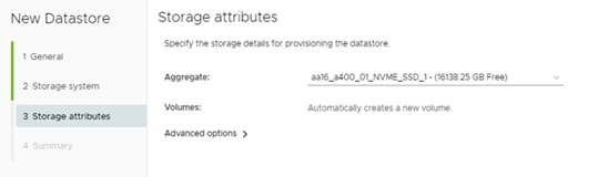
Step 11. Review the Summary and click FINISH.
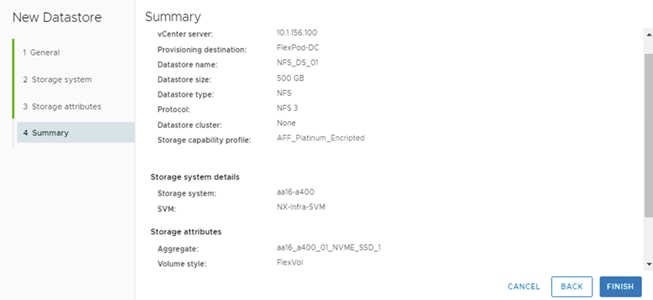
Step 12. The datastore is created and mounted on the hosts in the cluster. Click Refresh from the vSphere Web Client to see the newly created datastore.
Note: Before provision a datastore with encryption, be sure to enable storage cluster onboard key manager using the “security key-manager onboard enable” command or provide an external key manager with the “security key-manager external” command with additional information for the external key manager.
Note: Distributed datastore is supported from ONTAP 9.8, which provides FlexGroup volume on ONTAP storage. To create a Distributed Datastore across the ONTAP Cluster select NFS 4.1 and check the box for Distributed datastore data across the ONTAP Cluster as shown in the example below.
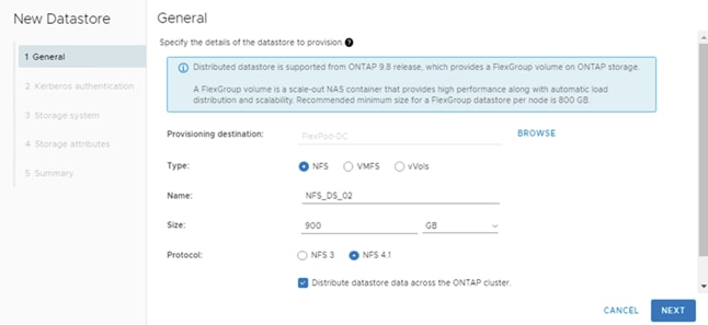
Procedure 9. Provision FC Datastore
Step 1. From the vCenter console, click Menu > ONTAP tools.
Step 2. From the ONTAP tools Home page, click Overview.
Step 3. From the Getting Started tab, click Provision.
Step 4. Click Browse to select the destination to provision the datastore.
Step 5. Select the type as VMFS and Enter the datastore name.
Step 6. Provide the size of the datastore and the FC Protocol.
Step 7. Check the Use storage capability profile and click NEXT.
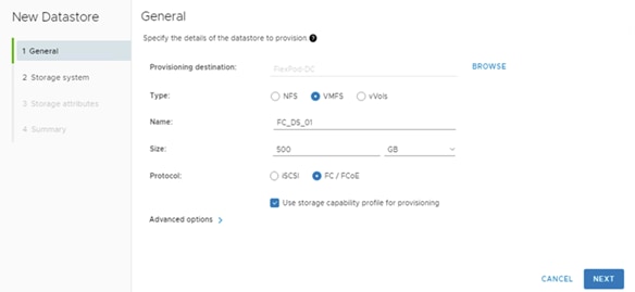
Step 8. Select the Storage Capability Profile, Storage System, and the desired Storage VM to create the datastore.
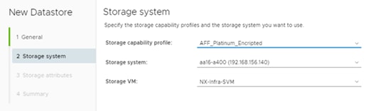
Step 9. Click NEXT.
Step 10. Select the aggregate name and click NEXT.
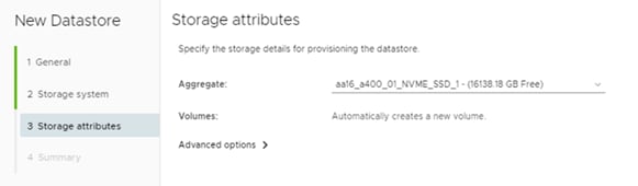
Step 11. Review the Summary and click FINISH.
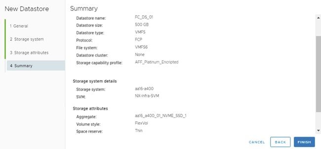
Step 12. The datastore is created and mounted on all the hosts in the cluster. Click Refresh from the vSphere Web Client to see the newly created datastore.
Procedure 10. Create Virtual Machine with Assigned VM Storage Policy
Step 1. Log into vCenter and navigate to the VMs and Templates tab and click to select the datacenter (for example, FlexPod-DC).
Step 2. Click Actions and click New Virtual Machine.
Step 3. Click Create a new virtual machine and click NEXT.
Step 4. Enter a name for the VM and select the datacenter (for example, FlexPod-DC).
Step 5. Select the cluster (for example, FlexPod-Management) and click NEXT.
Step 6. Select the VM storage policy from the selections and select a compatible datastore. Click NEXT.
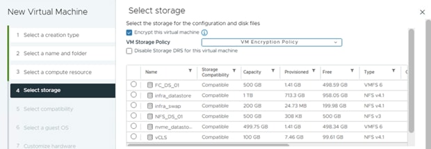
Step 7. Select Compatibility (for example, ESXi 8.0 or later) and click NEXT.
Step 8. Select the Guest OS and click NEXT.
Step 9. Customize the hardware for the VM and click NEXT.
Step 10. Review the details and click FINISH.
Note: By selecting the VM storage policy in Step 6, the VM will be deployed on the compatible datastores.
Virtual Volumes – vVol (Optional)
NetApp VASA Provider enables customers to create and manage VMware virtual volumes (vVols). A vVols datastore consists of one or more FlexVol volumes within a storage container (also called "backing storage"). A virtual machine can be spread across one vVols datastore or multiple vVols datastores. All of the FlexVol volumes within the storage container must use the same protocol (NFS, iSCSI, or FCP) and the same SVMs.
For more information on vVOL datastore configuration, see: https://www.cisco.com/c/en/us/td/docs/unified_computing/ucs/UCS_CVDs/flexpod_xseries_vmware_7u2.html#VirtualVolumesvVolOptional
NetApp SnapCenter Plug-in 4.8 Installation
SnapCenter Software is a centralized and scalable platform that provides application-consistent data protection for applications, databases, host file systems, and VMs running on ONTAP systems anywhere in the Hybrid Cloud.
NetApp SnapCenter Architecture
The SnapCenter platform is based on a multitier architecture that includes a centralized management server (SnapCenter Server) and a SnapCenter host agent. The host agent that performs virtual machine and datastore backups for VMware vSphere is the SnapCenter Plug-in for VMware vSphere. It is packaged as a Linux appliance (Debian-based Open Virtual Appliance format) and is no longer part of the SnapCenter Plug-ins Package for Windows. Additional information on deploying SnapCenter server for application backups can be found in the documentation listed below.
This guide focuses on deploying and configuring the SnapCenter plug-in for VMware vSphere to protect virtual machines and VM datastores.
Note: You must install SnapCenter Server and the necessary plug-ins to support application-consistent backups for Microsoft SQL, Microsoft Exchange, Oracle databases and SAP HANA. Application-level protection is beyond the scope of this deployment guide.
Note: Refer to the SnapCenter documentation for more information or the application specific CVD’s and technical reports for detailed information on how to deploy SnapCenter for a specific application configuration:
● SnapCenter Documentation: https://docs.netapp.com/us-en/snapcenter/index.html
● Deploy FlexPod Datacenter for Microsoft SQL Server 2019 with VMware 7.0 on Cisco UCS B200 M6 and NetApp ONTAP 9.8: https://www.cisco.com/c/en/us/products/collateral/servers-unified-computing/ucs-b-series-blade-servers/flexpod-sql-2019-vmware-on-ucs-netapp-ontap-wp.html
● SnapCenter Plug-in for VMware vSphere Documentation: SnapCenter Plug-in for VMware vSphere documentation (netapp.com)
Host and Privilege Requirements for the SnapCenter Plug-In for VMware vSphere
Review the following requirements before installing the SnapCenter Plug-in for VMware vSphere virtual appliance:
● SnapCenter Plug-in for VMware vSphere is deployed as a Linux based virtual appliance.
● Virtual appliances must not be deployed in a folder name with special characters.
● A separate, unique instance of the virtual appliance must be deployed for each vCenter Server.
| Port |
Requirement |
| 8080(HTTPS) bidirectional |
This port is used to manage the virtual appliance |
| 8144(HTTPs) bidirectional |
Communication between SnapCenter Plug-in for VMware vSphere and vCenter |
| 443 (HTTPS) |
Communication between SnapCenter Plug-in for VMware vSphere and vCenter |
License Requirements for SnapCenter Plug-In for VMware vSphere
The licenses listed in Table 9 are required on the ONTAP storage system to backup and restore VM’s in the virtual infrastructure:
Table 9. SnapCenter Plug-in for VMware vSphere License Requirements
| Product |
License Requirements |
| ONTAP |
SnapManager Suite: Used for backup operations One of these: SnapMirror or SnapVault (for secondary data protection regardless of the type of relationship) |
| ONTAP Primary Destinations |
To perform protection of VMware VMs and datastores the following licenses should be installed: SnapRestore: used for restoring operations FlexClone: used for mount and attach operations |
| ONTAP Secondary Destinations |
To perform protection of VMware VMs and datastores only: FlexClone: used for mount and attach operations |
| VMware |
vSphere Standard, Enterprise, or Enterprise Plus A vSphere license is required to perform restore operations, which use Storage vMotion. vSphere Essentials or Essentials Plus licenses do not include Storage vMotion. |
Note: It is recommended (but not required) to add SnapCenter Standard licenses to secondary destinations. If SnapCenter Standard licenses are not enabled on secondary systems, SnapCenter cannot be used after a failover operation. A FlexClone license on secondary storage is required to perform mount and attach operations. A SnapRestore license is required to perform restore operations.
Procedure 1. Deploy the SnapCenter Plug-In for VMware vSphere 4.8 using Ansible
Step 1. Clone the repository from https://github.com/NetApp/SnapCenter-Plug-in-for-VMware-vSphere.
Step 2. Follow the instructions in the README file in the repository to ensure the Ansible environment is configured properly.
Step 3. Update the following variable files:
hosts
group_vars/vcenter
vars/snapcenter_vmware_plugin_main.yml
Step 4. To invoke the ansible scripts, use the following command:
ansible-playbook -i hosts Setup_SnapCenter_VMware_Plugin.yml
Note: The above ansible playbook will install the SnapCenter Plug-in in vCenter and will also add ONTAP Storage System.
NetApp SnapCenter Plug-in 4.8 Configuration
Procedure 1. SnapCenter Plug-In for VMware vSphere in vCenter Server
Step 1. Navigate to VMware vSphere Web Client URL https://<vCenter Server>.
Note: If you’re currently logged into vCenter, logoff, close the open tab and sign-on again to access the newly installed SnapCenter Plug-in for VMware vSphere.
Step 2. After logging on, a blue banner will be displayed indicating the SnapCenter plug-in was successfully deployed. Click Refresh to activate the plug-in.
Step 3. From the VMware vSphere Web Client page, select Menu > SnapCenter Plug-in for VMware vSphere to launch the SnapCenter Plug-in for VMware GUI.
Step 4. When the storage system is added, you can create backup policies and take scheduled backup of VMs and datastores. The SnapCenter plug-in for VMware vSphere allows backup, restore and on-demand backups.
For more information on backup policy configuration, refer to this CVD: https://www.cisco.com/c/en/us/td/docs/unified_computing/ucs/UCS_CVDs/flexpod_xseries_vmware_7u2.html#FlexPodManagementToolsSetup
Active IQ Unified Manager 9.12 Installation
Active IQ Unified Manager enables you to monitor and manage the health and performance of ONTAP storage systems and virtual infrastructure from a single interface. Unified Manager provides a graphical interface that displays the capacity, availability, protection, and performance status of the monitored storage systems. Active IQ Unified Manager is required to integrate NetApp storage with Cisco Intersight.
This subject describes the procedure to deploy NetApp Active IQ Unified Manager 9.12 as a virtual appliance. Table 10 lists the recommended configuration for the VM.
Table 10. Virtual Machine Configuration
| Hardware Configuration |
Recommended Settings |
| RAM |
12 GB |
| Processors |
4 CPUs |
| CPU Cycle Capacity |
9572 MHz total |
| Free Disk Space/virtual disk size |
5 GB - Thin provisioned 152 GB – Thick provisioned |
Note: There is a limit to the number of nodes that a single instance of Active IQ Unified Manager can monitor before a second instance of Active IQ Unified Manager is needed. See the Unified Manager Best Practices Guide (TR-4621) for more details.
Procedure 1. Install NetApp Active IQ Unified Manager 9.12 using Ansible
Step 1. Clone the repository from https://github.com/NetApp/Active-IQ-Unified-Manager.
Step 2. Follow the instructions in the README file in the repository to ensure the Ansible environment is configured properly.
Step 3. Update the variable files as mentioned in the README document in the repository.
Step 4. To install AIQUM and add an ONTAP cluster, invoke the below ansible playbook:
ansible-playbook aiqum.yml -t aiqum_setup
Configure Active IQ Unified Manager
Procedure 1. Initial Setup
Step 1. Launch a web browser and log into Active IQ Unified Manager using the URL shown in the VM console and log in with the admin user.
Step 2. Enter the email address that Unified Manager will use to send alerts and the mail server configuration. Click Continue.
Step 3. Select Agree and Continue on the Set up AutoSupport configuration.
Step 4. Check the box for Enable API Gateway and click Continue.
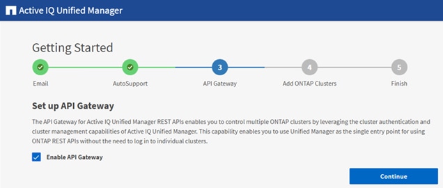
Step 5. Skip the following steps if the ONTAP cluster has already been added by the Ansible automation for deploying the AIQUM as shown in the recently added cluster below.
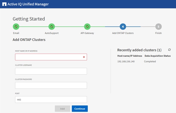
Step 6. Add the ONTAP cluster if needed by entering the ONTAP cluster hostname or IP address and the admin login credentials.
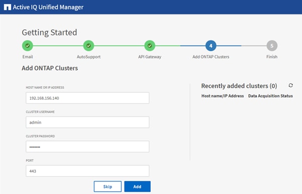
Step 7. Click Add.
Step 8. Click Yes to trust the self-signed cluster certificate and finish adding the storage system.
Note: The initial discovery process can take up to 15 minutes to complete.
Step 9. Click Finish to complete initial AIQUM setup.
Procedure 2. Review Security Compliance with Active IQ Unified Manager
Active IQ Unified Manager identifies issues and makes recommendations to improve the security posture of ONTAP. Active IQ Unified Manager evaluates ONTAP storage based on recommendations made in the Security Hardening Guide for ONTAP 9. Items are identified according to their level of compliance with the recommendations. Review the Security Hardening Guide for NetApp ONTAP 9 (TR-4569) for additional information and recommendations for securing ONTAP 9.
Note: All events identified do not inherently apply to all environments, for example, FIPS compliance.
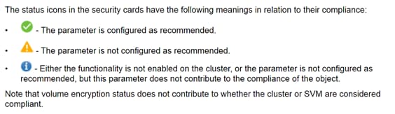
Step 1. Navigate to the URL of the Active IQ Unified Manager and login.
Step 2. Select the Dashboard from the left menu bar in Active IQ Unified Manager.
Step 3. Locate the Security card and note the compliance level of the cluster and SVM.
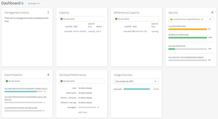
Step 4. Click the blue arrow to expand the findings.
Step 5. Locate Individual Cluster section and the Cluster Compliance card. From the drop-down list select View All.
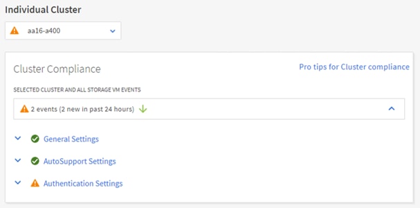
Step 6. Select an event from the list and click the name of the event to view the remediation steps.
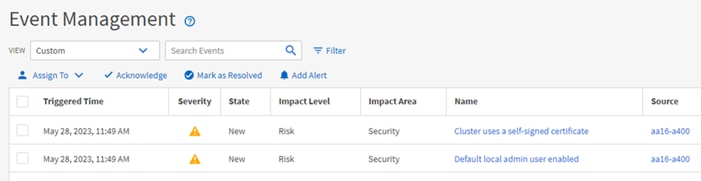
Step 7. Remediate the risk if applicable to current environment and perform the suggested actions to fix the issue.
Remediate Security Compliance Findings
Note: Active IQ identifies several security compliance risks after installation that can be immediately corrected to improve the security posture of ONTAP. Click on the event name to get more information and suggested actions to fix the issue.
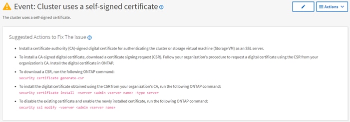
Deploy Cisco Intersight Assist Appliance
Cisco Intersight works with NetApp’s ONTAP storage and VMware vCenter using third-party device connectors and Cisco Nexus and MDS switches using Cisco device connectors. Since third-party infrastructure and Cisco switches do not contain any usable built-in Intersight device connector, Cisco Intersight Assist virtual appliance enables Cisco Intersight to communicate with these devices.
Note: A single Cisco Intersight Assist virtual appliance can support both NetApp ONTAP storage, VMware vCenter, and Cisco Nexus and MDS switches.
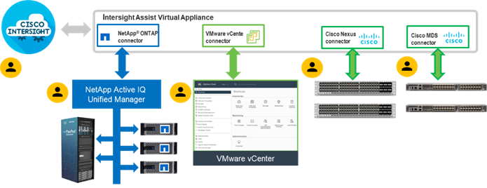
Procedure 1. Install Cisco Intersight Assist
Step 1. To install Cisco Intersight Assist from an Open Virtual Appliance (OVA), download the latest release of the Cisco Intersight Virtual Appliance for vSphere from https://software.cisco.com/download/home/286319499/type/286323047/release/1.0.9-588.
Note: Download the latest release.
Procedure 2. Set up DNS entries
Step 1. Setting up Cisco Intersight Virtual Appliance requires an IP address and 2 hostnames for that IP address. The hostnames must be in the following formats:
● myhost.mydomain.com: A hostname in this format is used to access the GUI. This must be defined as an A record and PTR record in DNS. The PTR record is required for reverse lookup of the IP address. If an IP address resolves to multiple hostnames, the first one in the list is used.
● dc-myhost.mydomain.com: The dc- must be prepended to your hostname. This hostname must be defined as the CNAME of myhost.mydomain.com. Hostnames in this format are used internally by the appliance to manage device connections.
Step 2. In this lab deployment the following information was used to deploy a Cisco Intersight Assist VM:
● Hostname: nx-intersight-assist.flexpod.cisco.com
● IP address: 10.1.156.107
● DNS Entries (Windows AD/DNS):
◦ A Record
![]()
◦ CNAME:
![]()
◦ PTR (reverse lookup):
![]()
For more information, go to: https://www.cisco.com/c/en/us/td/docs/unified_computing/Intersight/b_Cisco_Intersight_Appliance_Getting_Started_Guide/b_Cisco_Intersight_Appliance_Install_and_Upgrade_Guide_chapter_00.html.
Procedure 3. Deploy Cisco Intersight OVA
Note: Ensure that the appropriate entries of type A, CNAME, and PTR records exist in the DNS, as explained in the previous section.
Step 1. Log into the vSphere Client and select Inventory.
Step 2. In the Inventory list, right-click the cluster and click Deploy OVF Template.
Step 3. Select Local file and click UPLOAD FILES. Browse to and select the intersight-appliance-installer-vsphere-1.0.9-588.ova or the latest release file and click Open. Click NEXT.
Step 4. Name the Intersight Assist VM and select the location. Click NEXT.
Step 5. Select the cluster and click NEXT.
Step 6. Review details, click Ignore, and click NEXT.
Step 7. Select the Assist deployment configuration. Click NEXT.
Step 8. Select the appropriate datastore (for example, infra_datastore) for storage and select the Thin Provision virtual disk format. Click NEXT.
Step 9. Using the pulldown, select the appropriate management network (for example, IB-MGMT Network) for the OVA and click OK. Click NEXT.
Note: The Cisco Intersight Assist VM must be able to access both the IB-MGMT network on FlexPod and Intersight.com. Select and configure the management network appropriately. If selecting IB-MGMT network on FlexPod, make sure the routing and firewall is setup correctly to access the Internet.
Step 10. Fill in all values to customize the template. Click NEXT.
Step 11. Review the deployment information and click FINISH to deploy the appliance.
Step 12. When the OVA deployment is complete, right-click the Intersight Assist VM and click Edit Settings.
Step 13. Expand CPU and verify the socket configuration. For example, in the following deployment, on a 2-socket system, the VM was configured for 16 sockets:
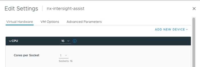
Step 14. Adjust the Cores per Socket so that the number of Sockets matches the server CPU configuration (2 sockets in this deployment):
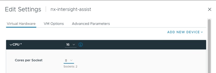
Step 15. Click OK.
Step 16. Right-click the Intersight Assist VM and select Power > Power On.
Step 17. When the VM powers on and login prompt is visible (use remote console), connect to https://intersight-assist-fqdn.
Note: It may take a few minutes for https://intersight-assist-fqdn to respond.
Step 18. Navigate the security prompts and select Install Assist. Click Start.
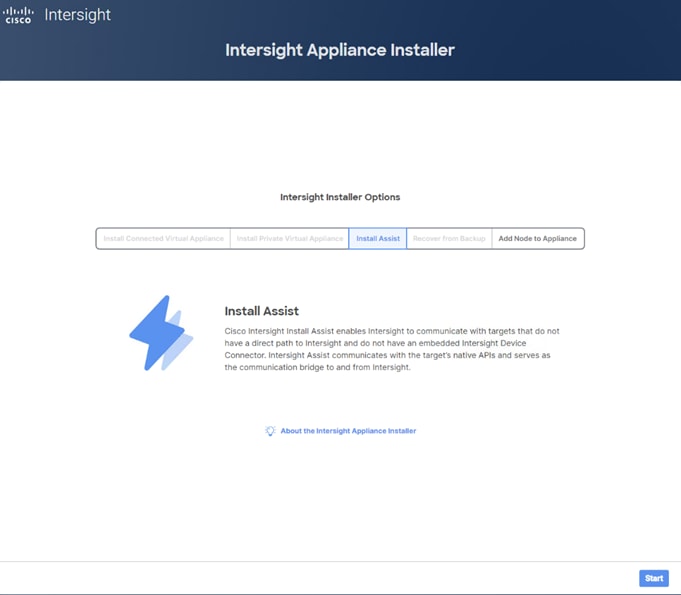
Note: The Cisco Intersight Assist VM needs to be claimed in Cisco Intersight using the Device ID and Claim Code information visible in the GUI.
Step 19. Log into Cisco Intersight and connect to the appropriate account.
Step 20. From Cisco Intersight, select System, then click Admin > Targets.
Step 21. Click Claim a New Target. Select Cisco Intersight Assist and click Start. Click OK to acknowledge the information about Cisco Intersight Workload Optimizer.
Step 22. Copy and paste the Device ID and Claim Code shown in the Intersight Assist web interface to the Cisco Intersight Device Claim window.
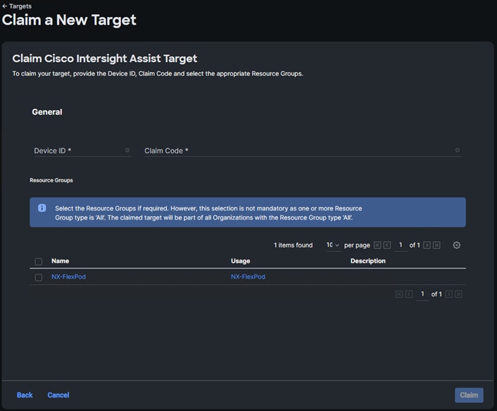
Step 23. Select the Resource Group and click Claim. Intersight Assist will now appear as a claimed device.
Step 24. In the Intersight Assist web interface, verify that Intersight Assist is Claimed Successfully, and click Continue.
Step 25. Verify success of the DNS Test and click Next.
Step 26. Accept the default Internal Network IP and click Next.
Note: The Cisco Intersight Assist software will now be downloaded and installed into the Intersight Assist VM. This can take up to an hour to complete.
Step 27. When the software download is complete, an Intersight Assist login screen will appear.
Step 28. Log into Intersight Assist with the admin user and the password supplied in the OVA installation. Check the Intersight Assist status and log out of Intersight Assist.
Claim VMware vCenter using Cisco Intersight Assist Appliance
Procedure 1. Claim the vCenter from Cisco Intersight
Step 1. Log into Cisco Intersight and connect to the account for this FlexPod.
Step 2. Go to System > Admin > Targets and click Claim a New Target.
Step 3. Under Select Target Type, select VMware vCenter under Hypervisor and click Start.
Step 4. In the VMware vCenter window, verify the correct Intersight Assist is selected.
Step 5. Fill in the vCenter information. It is recommended to use a user other than administrator@vsphere.local for this connection to remove visibility to the vCLS VMs. If Intersight Workflow Optimizer (IWO) will be used, turn on Datastore Browsing Enabled and Guest Metrics Enabled. Do not Enable HSM. Click Claim.
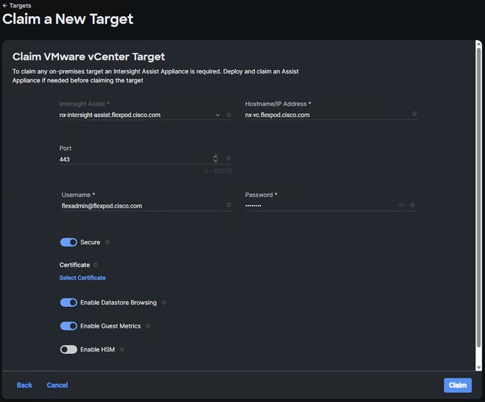
Step 6. After a few minutes, the VMware vCenter will show Connected in the Targets list and will also appear under Infrastructure Service > Operate > Virtualization.
Step 7. Detailed information obtained from the vCenter can now be viewed by clicking Infrastructure Service > Operate > Virtualization and selecting the Datacenters tab. Other VMware vCenter information can be obtained by navigating through the Virtualization tabs.
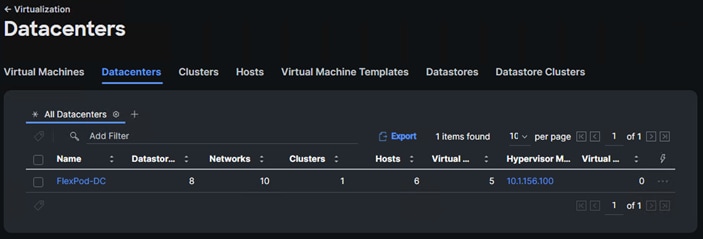
Procedure 2. Interact with Virtual Machines
VMware vCenter integration with Cisco Intersight allows you to directly interact with the virtual machines (VMs) from the Cisco Intersight dashboard. In addition to obtaining in-depth information about a VM, including the operating system, CPU, memory, host name, and IP addresses assigned to the virtual machines, you can use Cisco Intersight to perform the following actions on the virtual machines:
● Start/Resume
● Stop
● Soft Stop
● Suspend
● Reset
● Launch VM Console
Step 1. Log into Cisco Intersight and connect to the account for this FlexPod.
Step 2. Go to Infrastructure Service > Operate > Virtualization.
Step 3. Click the Virtual Machines tab.
Step 4. Click “…” to the right of a VM and interact with various VM options.
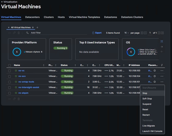
Step 5. To gather more information about a VM, click a VM name. The same interactive options are available under Actions.
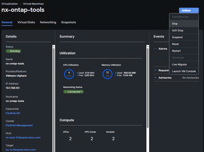
Claim NetApp Active IQ Manager using Cisco Intersight Assist Appliance
Procedure 1. Claim the NetApp Active IQ Unified Manager into Cisco Intersight
Step 1. Log into Cisco Intersight and connect to the account for this FlexPod.
Step 2. From Cisco Intersight, click System > Admin > Targets.
Step 3. Click Claim a New Target. In the Select Target Type window, select NetApp Active IQ Unified Manager under Storage and click Start.
Step 4. In the Claim NetApp Active IQ Unified Manager Target window, verify the correct Intersight Assist is selected.
Step 5. Fill in the NetApp Active IQ Unified Manager information and click Claim.
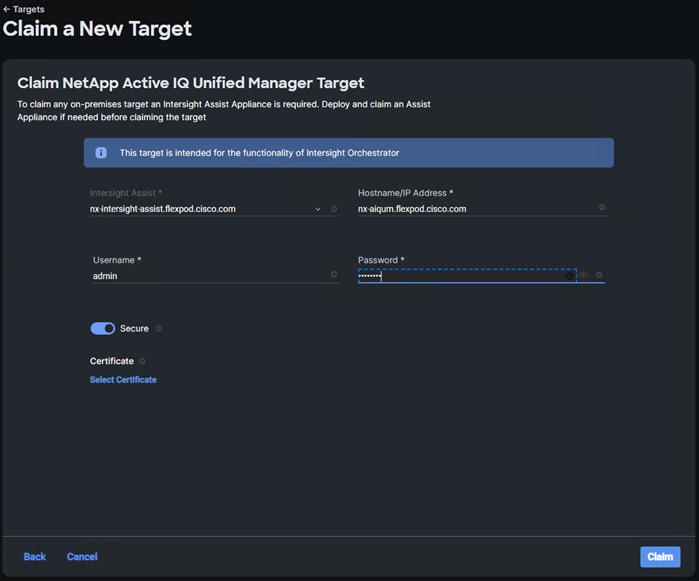
Step 6. After a few minutes, the NetApp ONTAP Storage configured in the Active IQ Unified Manager will appear under Infrastructure Service > Operate > Storage tab.
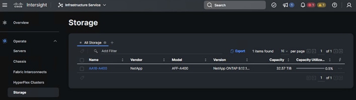
Step 7. Click the storage cluster name to see detailed General, Inventory, and Checks information on the storage.
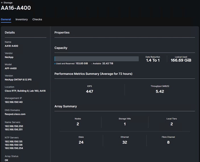
Step 8. Click My Dashboard > Storage to see storage monitoring widgets.
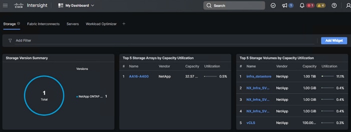
Claim Cisco Nexus Switches using Cisco Intersight Assist Appliance
Procedure 1. Claim Cisco Nexus Switches
Step 1. Log into Cisco Intersight and connect to the account for this FlexPod.
Step 2. From Cisco Intersight, click System > Admin > Targets.
Step 3. Click Claim a New Target. In the Select Target Type window, select Cisco Nexus Switch under Network and click Start.
Step 4. In the Claim Cisco Nexus Switch Target window, verify the correct Intersight Assist is selected.
Step 5. Fill in the Cisco Nexus Switch information and click Claim.
Note: You can use the admin user on the switch.
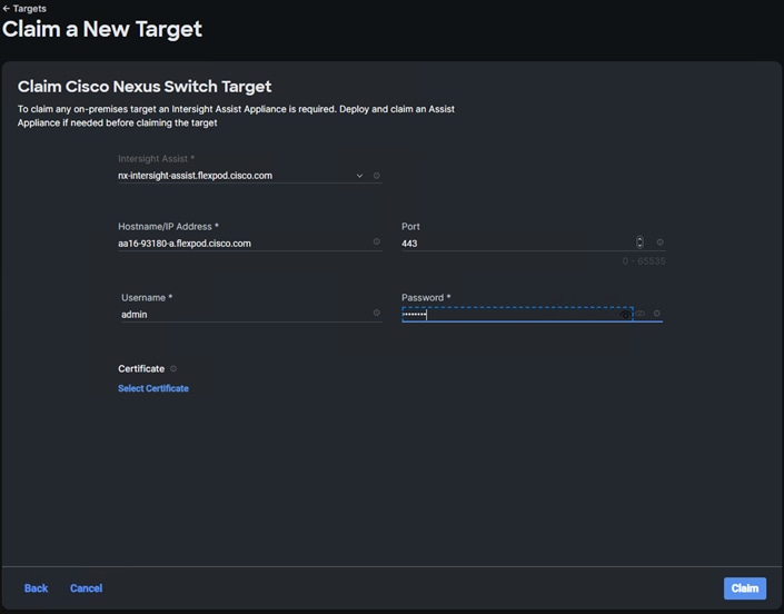
Step 6. Repeat steps 1 - 5 to add the second Cisco Nexus Switch.
Step 7. After a few minutes, the two switches will appear under Infrastructure Service > Operate > Networking > Ethernet Switches.
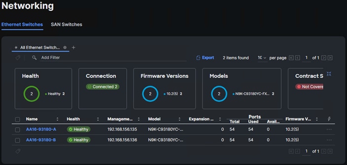
Step 8. Click one of the switch names to get detailed General and Inventory information on the switch.
Claim Cisco MDS Switches using Cisco Intersight Assist Appliance
Procedure 1. Claim Cisco MDS Switches (if they are part of the FlexPod)
Step 1. Log into Cisco Intersight and connect to the account for this FlexPod.
Step 2. From Cisco Intersight, click System > Admin > Targets.
Step 3. Click Claim a New Target. In the Select Target Type window, select Cisco MDS Switch under Network and click Start.
Step 4. In the Claim Cisco MDS Switch Target window, verify the correct Intersight Assist is selected.
Step 5. Fill in the Cisco MDS Switch information including use of Port 8443 and click Claim.
Note: You can use the admin user on the switch.
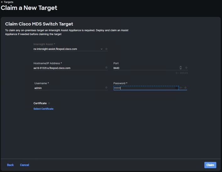
Step 6. Repeat the steps in this procedure to add the second Cisco MDS Switch.
Step 7. After a few minutes, the two switches will appear under Infrastructure Service > Operate > Networking > SAN Switches.
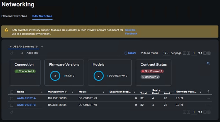
Note: Cisco MDS switches are still under Tech Preview in Intersight. Viewing information about the switches is fine, but if this is a production FlexPod, Intersight Cloud Orchestrator tasks and workflows should not be executed against these switches.
Step 8. Click one of the switch names to get detailed General and Inventory information on the switch.
Create a FlexPod Integrated System
Procedure 1. Creating a FlexPod Integrated System
Step 1. Log into Cisco Intersight and connect to the account for this FlexPod.
Step 2. From Cisco Intersight, click Infrastructure Service > Operate > Integrated Systems.
Step 3. Click Create Integrated System. In the center pane, select FlexPod and click Start.
Step 4. Select the correct Organization, provide a suitable name, and optionally any Tags or a Description and click Next.
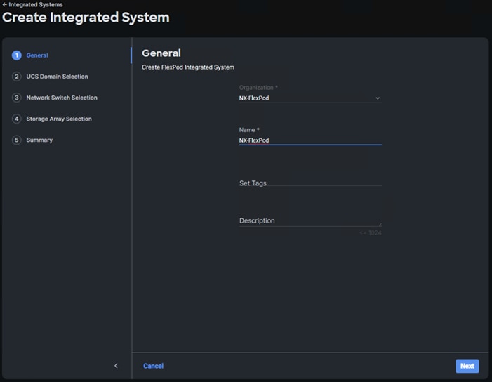
Step 5. Select the UCS Domain used in this FlexPod and click Next.
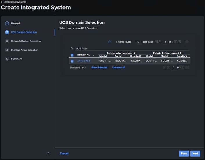
Step 6. Select the two Cisco Nexus switches used in this FlexPod and click Next.
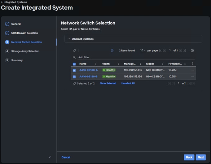
Step 7. Select all NetApp storage used in this FlexPod and click Next.
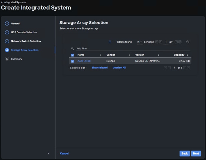
Step 8. Review the Summary information and click Create. After a few minutes, the FlexPod Integrated System will appear under Integrated Systems.
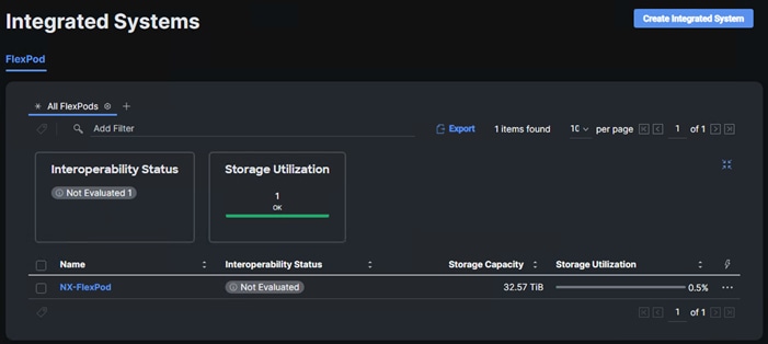
Note: You can click the “…” to the right of the FlexPod name and run an Interoperability check on the FlexPod. This check will take information on the FlexPod already checked against the Cisco UCS Hardware Compatibility List (HCL) and also check this information against the NetApp Interoperability Matrix Tool (IMT).
Step 9. Click the FlexPod name to see detailed General, Inventory, and Interoperability data on the FlexPod Integrated System.
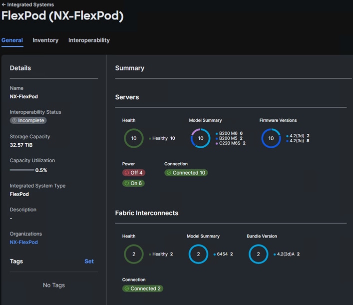
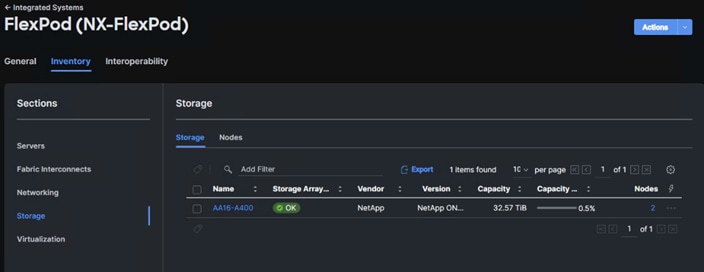
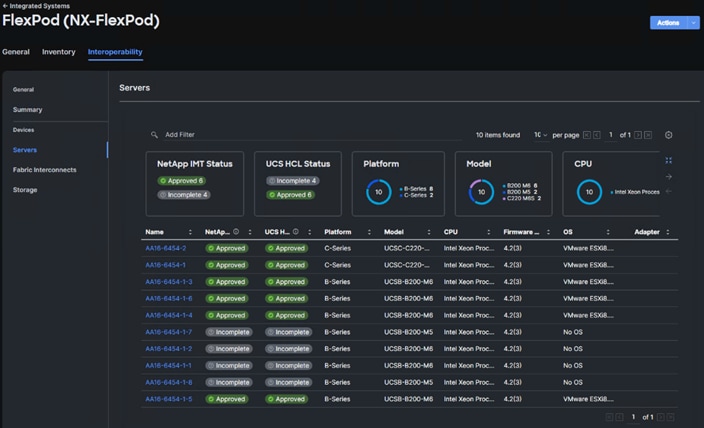
Note: The servers that were not powered on during Run Interoperability Check were categorized as Incomplete Devices in the Interoperability Summary view.
Cisco Nexus Dashboard Fabric Controller (NDFC)–SAN
If you have fibre-channel SAN in your FlexPod, Cisco NDFC-SAN can be used to monitor, configure, and analyze Cisco fibre channel fabrics. This configuration will setup a single-node Nexus Dashboard on a Cisco UCS server and then deploy NDFC-SAN. SAN Analytics can be added to provide insights into your fabric by allowing you to monitor, analyze, identify, and troubleshoot performance issues.
Prerequisites
The following prerequisites need to be configured:
● Licensing. Cisco NDFC-SAN includes a 60-day server-based trial license that can be used to monitor and configure Cisco MDS Fibre Channel switches and Cisco Nexus switches utilizing Nexus SAN switching. Both NDFC or DCNM server-based and switch-based licenses can be purchased. Additionally, SAN Insights and SAN Analytics requires an additional switch-based license on each switch. Cisco MDS 32Gbps Fibre Channel switches provide a 120-day grace period to trial SAN Analytics.
Note: If using Cisco Nexus 93360YC-FX2, 93360YC-FX2, or 9336C-FX2-E for SAN switching, the Nexus switch does not support SAN Analytics.
● Passwords. Cisco NDFC-SAN passwords should adhere to the following password requirements:
◦ It must be at least eight characters long and contain at least one alphabet and one numeral.
◦ It can contain a combination of alphabets, numerals, and special characters.
◦ Do not use any of these special characters in the DCNM password for all platforms: <SPACE> " & $ % ' ^ = < > ; : ` \ | / , .*
● NDFC SNMPv3 user on switches. Each switch (both Cisco MDS and Nexus) needs an SNMPv3 user added for NDFC to use to query and configure the switch. On each switch, enter the following command in configure terminal mode (in the example, the userid is snmpuser):
snmp-server user snmpadmin network-admin auth sha <password> priv aes-128 <privacy-password>
● On Cisco MDS switches, type show run. If snmpadmin passphrase lifetime 0 is present, enter username snm-padmin passphrase lifetime 99999 warntime 14 gracetime 3.
Note: It is important to use auth type sha and privacy auth aes-128 for both the switch and UCS snmpadmin users.
● Type “copy run start” on all switches to save the running configuration to the startup configuration.
● In Cisco UCS Manager, select Admin > Communication Management > Communication Services. Set the SNMP Admin State to Enabled. Under SNMP Users, add the same snmpadmin user with SHA and AES-128 with the same passwords set in the switches. Click Save Changes and then click OK to confirm this.
Procedure 1. Deploy the Cisco Nexus Dashboard OVA and then NDFC-SAN
Step 1. Download the Cisco Nexus Dashboard VM Image 2.3(2d) from https://software.cisco.com/download/home/281722751/type/282088134/release/12.1.2e.
Step 2. The single-node Nexus Dashboard should be installed on a server that is not part of a cluster since Nexus Dashboard does not support vMotion or VMware DRS. If an extra server was provisioned for this purpose, move it out to the Datacenter level in vCenter. Otherwise, follow the procedures in this document to provision a server at the Datacenter level. Make sure that it has a VMkernel port in the Infra-NFS subnet. For manual configuration of an ESXi host in a FlexPod, you can refer to https://www.cisco.com/c/en/us/td/docs/unified_computing/ucs/UCS_CVDs/flexpod_ucs_xseries_e2e_ontap_manual_deploy.html for everything except provisioning a Service Profile from template.
Step 3. Since Nexus Dashboard requires 3TB of disk space, it is recommended to place it in a separate datastore. Create a 3TB NFS datastore by right-clicking the Nexus Dashboard ESXi host and selecting NetApp ONTAP Tools > Provision Datastore.
Step 4. Name the datastore and set the size to 3TB. Select the NFS protocol in use in your environment and uncheck Use storage capability profile for provisioning. Click NEXT.
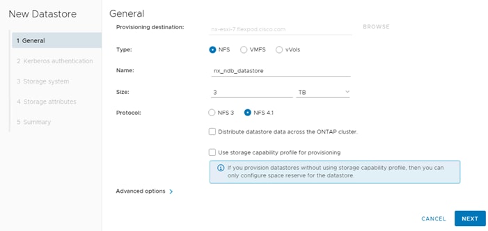
Step 5. If using NFS 4.1, leave “Don’t use Kerberos authentication” selected and click NEXT.
Step 6. Select the storage controller for this FlexPod and the Infra-SVM and click NEXT.
Step 7. Select the aggregate with the freest space. Expand Advanced options and make sure Space reserve is set to Thin. Click NEXT.
Step 8. Review the Summary and click FINISH and OK. ONTAP Tools will provision and mount the datastore on the Nexus Dashboard ESXi host.
Step 9. Right-click the Nexus Dashboard ESXi host and select Deploy OVF Template.
Step 10. Select Local file then click UPLOAD FILES. Navigate to select nd-dk9.2.3.2d.ova and click Open. Click NEXT.
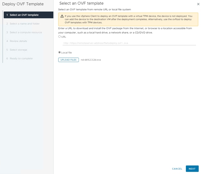
Step 11. Name the virtual machine and select the FlexPod-DC datacenter. Click NEXT.
Step 12. Select the Nexus Dashboard ESXi host and click NEXT.
Step 13. Review the details and click NEXT.
Step 14. Select the appropriate deployment configuration size and click NEXT.
Note: If using the SAN Insights and SAN Analytics feature, it is recommended to use the Data deployment.
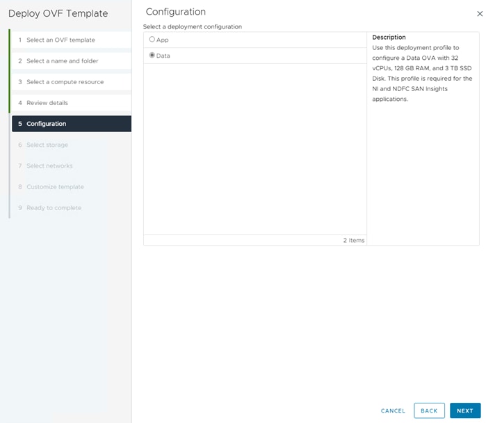
Step 15. Select the datastore previously configured and the Thin Provision virtual disk format. Click NEXT.
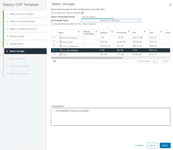
Step 16. Select IB-MGMT Network for the mgmt0 Source Network. Select OOB-MGMT Network for the fabric0 Source Network. Click NEXT.
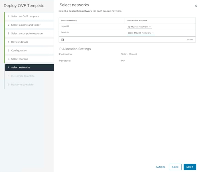
Step 17. Leave the Data Disk Size set to 3072. Fill in the rescue-user password, the management network address and subnet, and the management network gateway. Click NEXT.
Step 18. Review the settings and click FINISH to deploy the OVA.
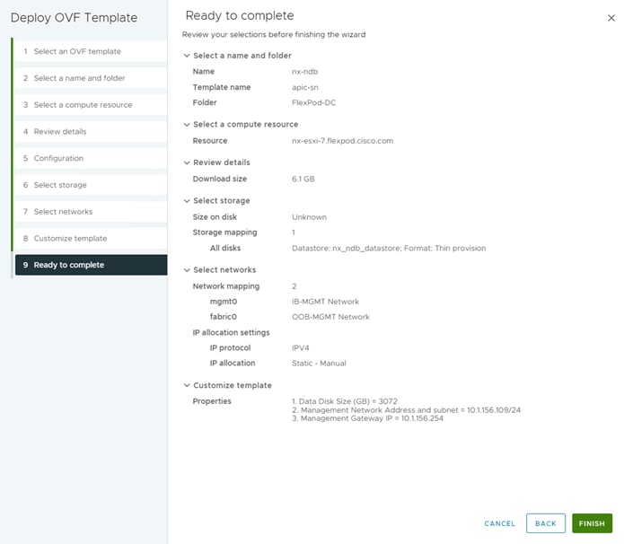
Step 19. After deployment is complete, right-click the newly deployed Nexus Dashboard VM and click Edit Settings. Expand CPU and adjust the Cores per Socket setting until the number of Sockets is set to match the number of CPUs in the UCS servers used in this deployment. The following example shows 2 sockets. Click OK.
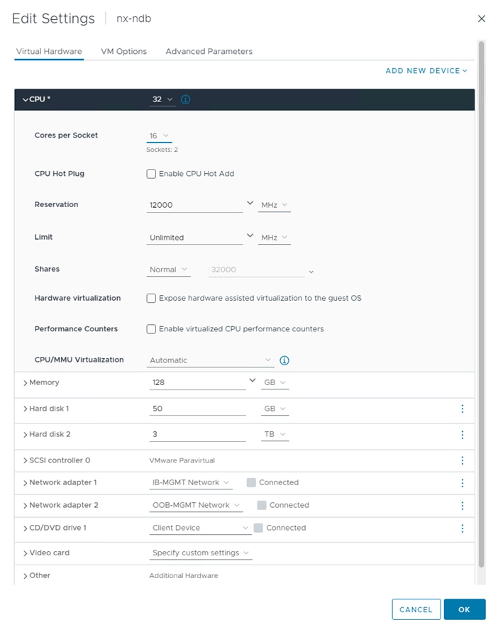
Step 20. Right-click the newly deployed Nexus Dashboard VM and click Open Remote Console. Once the console is up, click the green arrow to power on the VM. When the VM has powered up, open a web browser, and enter the URL displayed on the console.
Step 21. Navigate the security prompts, enter the password from the OVA deployment and click Begin Setup.
Step 22. Enter the Nexus Dashboard name, add NTP server IPs, and DNS server IPs. If your network does not have a proxy server, click the ![]() to the right of Proxy Server and select Skip. Click Confirm on the Warning. Expand View Advanced Settings. Add the DNS Search Domain and click Next.
to the right of Proxy Server and select Skip. Click Confirm on the Warning. Expand View Advanced Settings. Add the DNS Search Domain and click Next.
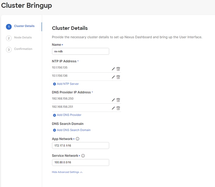
Step 23. The IB-MGMT Network information should already be filled in for the one Nexus Dashboard node being provisioned. Click the pencil icon to the right and fill in the Node Name, IPv4 Address/Mask and Gateway for the OOB-MGMT subnet interface. Click Update.
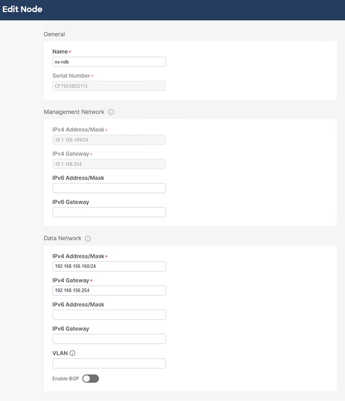
Step 24. Click Next.
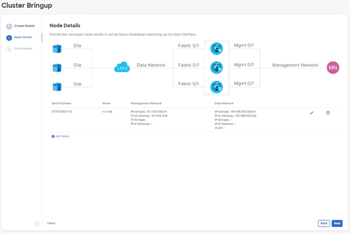
Step 25. Click Confirm Installation to confirm that a one-node Nexus Dashboard is being installed.
Step 26. Click Configure to begin the installation.
Step 27. Wait for the installation and Cluster Deployment to complete. You will need to refresh the browser and negotiate the security prompts to get the Welcome to Nexus Dashboard page.
Step 28. On the Welcome to Nexus Dashboard page, enter the admin Username and the password entered in the OVA installation and click Login.
Step 29. Click Let’s Go then click Do not show on login. Click Get Started.
Step 30. Click Done then click Go To Dashboard. At the top of the window, use the One View drop-down list to select Admin Console.
Step 31. On the left select Infrastructure then select Cluster Configuration. Click the pencil icon to the right of External Service Pools to add Data Service IP’s from the OOB-MGMT subnet. Add 3 Data Service IP’s from the OOB-MGMT subnet and click Save.
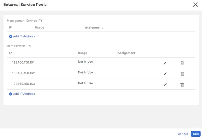
Step 32. On the left select Services. Select the App Store tab. Install NDFC by clicking Install under Nexus Dashboard Fabric Controller.
Step 33. Enter your Cisco ID and password and navigate Single Sign On (SSO).
Step 34. Close the Cookies window then click Agree and Download to accept the License Agreement and download NDFC. NDFC will progress through Downloading to Installing and finally to Installed.
Step 35. Select the Installed Services tab. Under Nexus Dashboard Fabric Controller, click Enable. The service will take a few minutes to enable.
Step 36. When Enable is replaced by Open under Nexus Dashboard Fabric Controller, click Open.
Step 37. Review the Nexus Dashboard Fabric Controller SAN Prerequisites which indicate 3 IPs in the OOB-MGMT subnet will be needed. Check Do not show this message again and click Get started.
Step 38. Click the circle to the right of SAN Controller, select Cisco as the OEM vendor, and click Confirm. Select all features that you plan to use and click Apply to start the SAN Controller. Wait until the SAN Controller and all Features are Started and have a green status indicator.
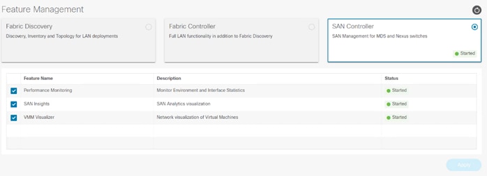
Procedure 2. Configure NDFC-SAN
Step 1. When the NDFC-SAN installation is complete, the browser should redirect to the SAN Controller.
Step 2. Click SAN > Fabrics to add the two SAN Fabrics. Under Actions, select Add Fabric.
Step 3. Proved a name for the A-side fabric. For the Fabric Seed Switch, enter the IP address of the Fabric A MDS or Nexus SAN switch. Leave Use SNMPv3/SSH checked and select SHA_AES for Authentication/Privacy. Enter the snmpadmin User Name and associated password. Check Use UCS Credentials. Enter admin for the UCS User Name and the associated password. Leave Use same SNMP credentials for UCS checked. Click Add.
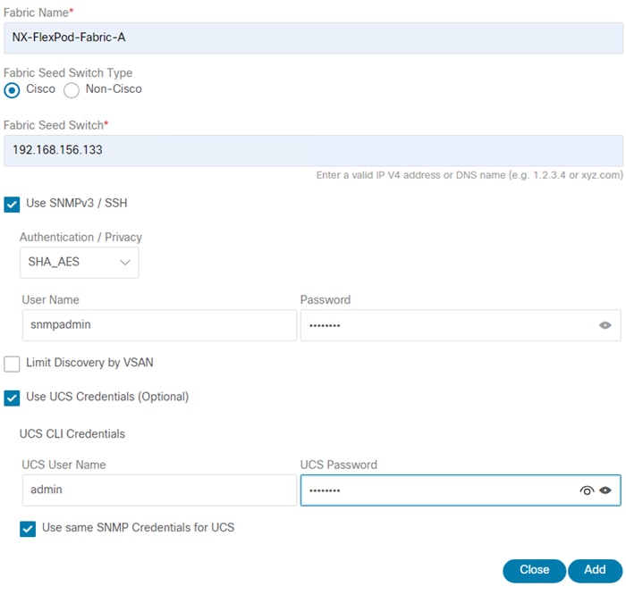
Step 4. Once the A-side fabric has been added, repeat Step 3 to add the B-side fabric.
Step 5. If you have purchased NDFC or DCNM server-based or switch-based licenses, follow the instructions that came with the licenses to install them. A new NDFC installation also has a 60-day trial license.
Step 6. Select SAN > Fabrics. Use the checkbox to select both Fabrics and under Actions select Configure Performance. Enable all desired Performance Data Collection Settings and click Apply then click Confirm.
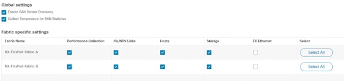
Step 7. If you have purchased and installed SAN Analytics licenses on your MDS switches, use the checkbox to select Fabric A and under Actions select Configure SAN Insights. Click Next. Select your Fabric A Cisco MDS switch. Under Subscriptions select the appropriate subscription. Under Install Query select Storage. Click Next. Click Next. On the ports connected to storage, select the type of metrics to be collected. Click Next. Click Commit to setup the storage ports on the MDS and to install the query and configure telemetry in the MDS. When both tasks have a status of Success, click Close. Repeat this process for Fabric B. After a few minutes, select Dashboards > SAN Insights. You should see that the SAN Controller is receiving SAN Insights records.
Step 8. ssh into each of the MDS switches and type “show license usage”. If you enable SAN Analytics in Step 7, each switch should show usage of a DCNM-SAN license and a SAN Analytics license.
Step 9. To configure Device Aliases for a fabric, go to SAN > Fabrics, click on the Fabric Name. On the right, click ![]() to pop out to the Fabric. Select the Device Aliases tab. Here, you can use a checkbox to select an existing Device Alias and under Actions either Edit or Delete it. To Add a Device Alias, under Actions select Add device alias. The first window shows WWPNs that have logged into the Fabric. If you want to add a Device Alias for one of these WWPNs, use the checkbox to select it and click Next. If your WWPN does not appear here, click Next to Pre-provision the device alias. When you have either edited or Pre-provisioned all device aliases, click Save Aliases to save them.
to pop out to the Fabric. Select the Device Aliases tab. Here, you can use a checkbox to select an existing Device Alias and under Actions either Edit or Delete it. To Add a Device Alias, under Actions select Add device alias. The first window shows WWPNs that have logged into the Fabric. If you want to add a Device Alias for one of these WWPNs, use the checkbox to select it and click Next. If your WWPN does not appear here, click Next to Pre-provision the device alias. When you have either edited or Pre-provisioned all device aliases, click Save Aliases to save them.
Step 10. To configure Zoning for a fabric, go to SAN > Zoning then select the appropriate Fabric, VSAN, and Switch. Select the Zoneset and then under Actions select Edit zones & members. You can then select a Zone on the left and see its members on the right. Under Actions, you can Add existing members to the zone. Select Device Alias and then add any needed Device Aliases to the zone. Zoning by Enhanced Device Alias is what has been setup in this FlexPod, and it is important to continue to add members by Device Alias. When you have changed the zones, you will need to Activate the Zoneset to implement the changes.
Note: For more information, see Cisco NDFC-SAN Controller Configuration Guide, Release 12.1.2e.
Cisco Intersight has recently added several metrics dashboards under My Dashboard. The My Dashboard service is a great place to start to get a summary of health and what needs attention when you first login and you can drill down from there to get additional details or take action. Recent additions include Power & Energy Metrics (Sustainability), Fabric Interconnect Metrics, and Server Metrics.
Procedure 1. View Metrics Dashboards
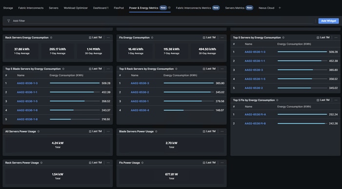
Step 2. To view the Fabric Interconnects Metrics Dashboard, in Cisco Intersight select My Dashboard then the Fabric Interconnects Metrics tab. Widgets showing fabric interconnect network statistics will be shown.
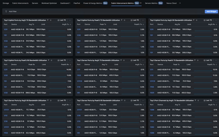
Step 3. To view the Servers Metrics Dashboard, in Cisco Intersight select My Dashboard then the servers Metrics tab. Widgets showing server temperature statistics will be shown.
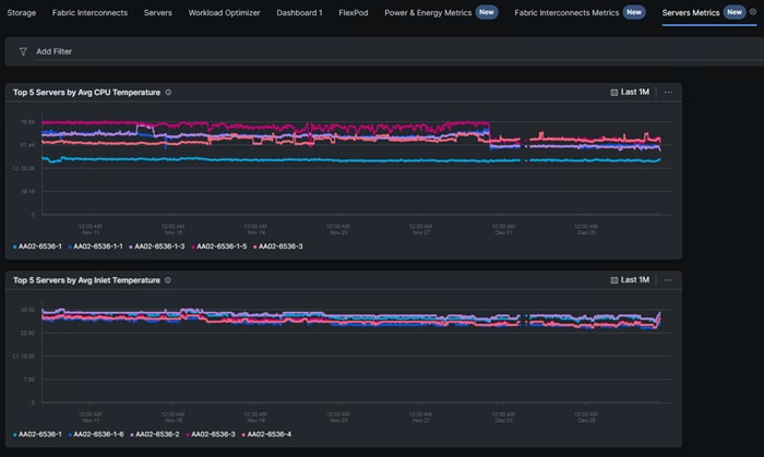
John George, Technical Marketing Engineer, Cisco Systems, Inc.
John has been involved in designing, developing, validating, and supporting the FlexPod Converged Infrastructure since it was developed 13 years ago. Before his role with FlexPod, he supported and administered a large worldwide training network and VPN infrastructure. John holds a master’s degree in Computer Engineering from Clemson University.
Kamini Singh, Technical Marketing Engineer, Hybrid Cloud Infra & OEM Solutions, NetApp
Kamini Singh is a Technical Marketing engineer at NetApp. She has more than four years of experience in data center infrastructure solutions. Kamini focuses on FlexPod hybrid cloud infrastructure solution design, implementation, validation, automation, and sales enablement. Kamini holds a bachelor’s degree in Electronics and Communication and a master’s degree in Communication Systems.
Roney Daniel, Technical Marketing Engineer, Hybrid Cloud Infra & OEM Solutions, NetApp Inc.
Roney Daniel is a Technical Marketing engineer at NetApp. He has over 25 years of experience in the networking industry. Prior to NetApp, Roney worked at Cisco Systems in various roles with Cisco TAC, Financial Test Lab, Systems and solution engineering BUs and Cisco IT. He has a bachelor's degree in Electronics and Communication engineering and is a data center Cisco Certified Internetwork Expert (CCIE 42731).
Acknowledgements
For their support and contribution to the design, validation, and creation of this Cisco Validated Design, the authors would like to thank:
● Haseeb Niazi, Principal Technical Marketing Engineer, Cisco Systems, Inc.
● Paniraja Koppa, Technical Marketing Engineer, Cisco Systems, Inc.
Appendix
This appendix contains the following:
● FlexPod with Cisco Nexus SAN Switching Configuration – Part 1
● FlexPod with Cisco Nexus 93360YC-FX2 SAN Switching Configuration – Part 2
● Create a FlexPod ESXi Custom ISO using VMware vCenter
● Active IQ Unified Manager User Configuration
● Active IQ Unified Manager vCenter Configuration
Note: The features and functionality explained in this Appendix are optional configurations which can be helpful in configuring and managing the FlexPod deployment.
FlexPod with Cisco Nexus SAN Switching Configuration – Part 1
If the Cisco Nexus switches are to be used for both LAN and SAN switching in the FlexPod configuration, either an automated configuration with Ansible or a manual configuration can be done. For either configuration method, the following base switch setup must be done manually. Figure 7 shows the validation lab cabling for this setup.
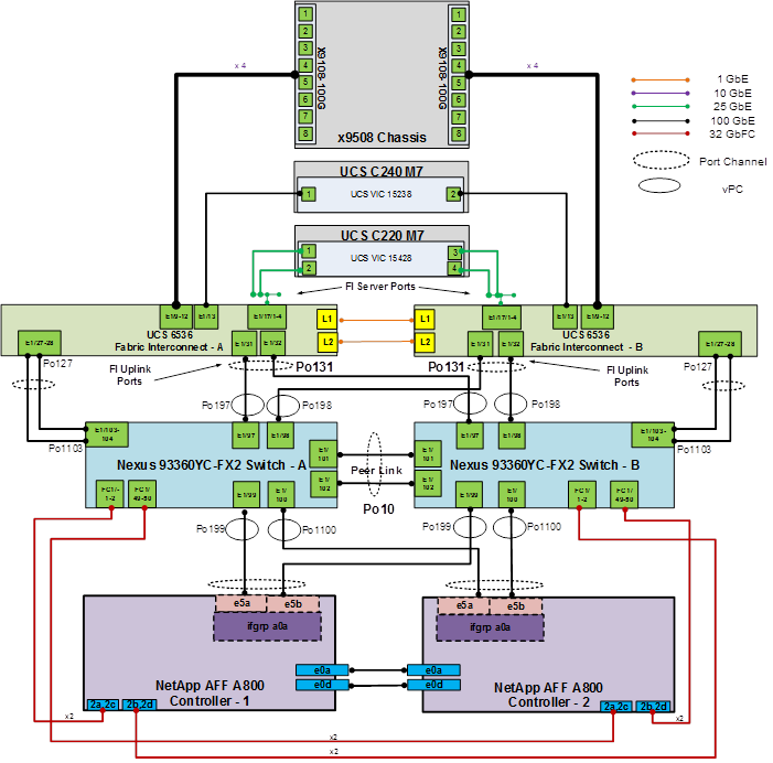
FlexPod Cisco Nexus 93360YC-FX2 SAN Switching Base Configuration
The following procedures describe how to configure the Cisco Nexus 93360YC-FX2 switches for use in a base FlexPod environment that uses the switches for both LAN and SAN switching. This procedure assumes you’re using Cisco Nexus 9000 10.2(5)M. This procedure also assumes that you have created an FCoE Uplink Port Channel on the appropriate ports in the Cisco UCS IMM Port Policies for each UCS fabric interconnect.
Procedure 1. Set Up Initial Configuration in Cisco Nexus 93360YC-FX2 A
Step 1. Configure the switch:
Note: On initial boot and connection to the serial or console port of the switch, the NX-OS setup should automatically start and attempt to enter Power on Auto Provisioning.
Abort Power On Auto Provisioning [yes - continue with normal setup, skip - bypass password and basic configuration, no - continue with Power On Auto Provisioning] (yes/skip/no)[no]: yes
Disabling POAP.......Disabling POAP
poap: Rolling back, please wait... (This may take 5-15 minutes)
---- System Admin Account Setup ----
Do you want to enforce secure password standard (yes/no) [y]: Enter
Enter the password for "admin": <password>
Confirm the password for "admin": <password>
Would you like to enter the basic configuration dialog (yes/no): yes
Create another login account (yes/no) [n]: Enter
Configure read-only SNMP community string (yes/no) [n]: Enter
Configure read-write SNMP community string (yes/no) [n]: Enter
Enter the switch name: <nexus-A-hostname>
Continue with Out-of-band (mgmt0) management configuration? (yes/no) [y]: Enter
Mgmt0 IPv4 address: <nexus-A-mgmt0-ip>
Mgmt0 IPv4 netmask: <nexus-A-mgmt0-netmask>
Configure the default gateway? (yes/no) [y]: Enter
IPv4 address of the default gateway: <nexus-A-mgmt0-gw>
Configure advanced IP options? (yes/no) [n]: Enter
Enable the telnet service? (yes/no) [n]: Enter
Enable the ssh service? (yes/no) [y]: Enter
Type of ssh key you would like to generate (dsa/rsa) [rsa]: Enter
Number of rsa key bits <1024-2048> [1024]: Enter
Configure the ntp server? (yes/no) [n]: Enter
Configure default interface layer (L3/L2) [L2]: Enter
Configure default switchport interface state (shut/noshut) [noshut]: shut
Enter basic FC configurations (yes/no) [n]: y
Configure default physical FC switchport interface state (shut/noshut) [shut]: Enter
Configure default switchport trunk mode (on/off/auto) [on]: auto
Configure default zone policy (permit/deny) [deny]: Enter
Enable full zoneset distribution? (yes/no) [n]: y
Configure CoPP system profile (strict/moderate/lenient/dense) [strict]: Enter
Would you like to edit the configuration? (yes/no) [n]: Enter
Step 2. Review the configuration summary before enabling the configuration:
Use this configuration and save it? (yes/no) [y]: Enter
Procedure 2. Set Up Initial Configuration in Cisco Nexus 93360YC-FX2 B
Step 1. Configure the switch:
Note: On initial boot and connection to the serial or console port of the switch, the NX-OS setup should automatically start and attempt to enter Power on Auto Provisioning.
Abort Power On Auto Provisioning [yes - continue with normal setup, skip - bypass password and basic configuration, no - continue with Power On Auto Provisioning] (yes/skip/no)[no]: yes
Disabling POAP.......Disabling POAP
poap: Rolling back, please wait... (This may take 5-15 minutes)
---- System Admin Account Setup ----
Do you want to enforce secure password standard (yes/no) [y]: Enter
Enter the password for "admin": <password>
Confirm the password for "admin": <password>
Would you like to enter the basic configuration dialog (yes/no): yes
Create another login account (yes/no) [n]: Enter
Configure read-only SNMP community string (yes/no) [n]: Enter
Configure read-write SNMP community string (yes/no) [n]: Enter
Enter the switch name: <nexus-B-hostname>
Continue with Out-of-band (mgmt0) management configuration? (yes/no) [y]: Enter
Mgmt0 IPv4 address: <nexus-B-mgmt0-ip>
Mgmt0 IPv4 netmask: <nexus-B-mgmt0-netmask>
Configure the default gateway? (yes/no) [y]: Enter
IPv4 address of the default gateway: <nexus-B-mgmt0-gw>
Configure advanced IP options? (yes/no) [n]: Enter
Enable the telnet service? (yes/no) [n]: Enter
Enable the ssh service? (yes/no) [y]: Enter
Type of ssh key you would like to generate (dsa/rsa) [rsa]: Enter
Number of rsa key bits <1024-2048> [1024]: Enter
Configure the ntp server? (yes/no) [n]: Enter
Configure default interface layer (L3/L2) [L2]: Enter
Configure default switchport interface state (shut/noshut) [noshut]: shut
Enter basic FC configurations (yes/no) [n]: y
Configure default physical FC switchport interface state (shut/noshut) [shut]: Enter
Configure default switchport trunk mode (on/off/auto) [on]: auto
Configure default zone policy (permit/deny) [deny]: Enter
Enable full zoneset distribution? (yes/no) [n]: y
Configure CoPP system profile (strict/moderate/lenient/dense) [strict]: Enter
Would you like to edit the configuration? (yes/no) [n]: Enter
Step 2. Review the configuration summary before enabling the configuration:
Use this configuration and save it? (yes/no) [y]: Enter
Note: SAN switching requires both the SAN_ENTERPRISE_PKG and FC_PORT_ACTIVATION_PKG licenses. Ensure these licenses are installed on each Nexus switch.
Note: This section is structured as a green field switch setup. If existing switches that are switching active traffic are being setup, execute this procedure down through Perform TCAM Carving and Configure Unified Ports in Cisco Nexus 93360YC-FX22 A and B first on one switch and then when that is completed, execute on the other switch.
Procedure 3. Install feature-set fcoe in Cisco Nexus 93360YC-FX2 A and B
Step 1. Run the following commands to set global configurations:
config t
install feature-set fcoe
feature-set fcoe
system default switchport trunk mode auto
system default switchport mode F
Note: These steps are provided in case the basic FC configurations were not configured in the switch setup script de-tailed in the previous section.
Procedure 4. Set System-Wide QoS Configurations in Cisco Nexus 93360YC-FX2 A and B
Step 1. Run the following commands to set global configurations:
config t
system qos
service-policy type queuing input default-fcoe-in-que-policy
service-policy type queuing output default-fcoe-8q-out-policy
service-policy type network-qos default-fcoe-8q-nq-policy
copy run start
Procedure 5. Perform TCAM Carving and Configure Unified Ports (UP) in Cisco Nexus 93360YC-FX2 A and B
Note: SAN switching requires TCAM carving for lossless fibre channel no-drop support. Also, unified ports need to be converted to fc ports.
Note: On the Cisco Nexus 93360YC-FX2, UP ports are converted to FC in groups of 4 in columns, for example, 1,2,49,50.
Step 1. Run the following commands:
hardware access-list tcam region ing-racl 1536
hardware access-list tcam region ing-ifacl 256
hardware access-list tcam region ing-redirect 256
slot 1
port 1-8 type fc
copy running-config startup-config
reload
This command will reboot the system. (y/n)? [n] y
Step 2. After the switch reboots, log back in as admin. Run the following commands:
show hardware access-list tcam region |i i ing-racl
show hardware access-list tcam region |i i ing-ifacl
show hardware access-list tcam region |i i ing-redirect
show int status
FlexPod Cisco Nexus 93360YC-FX2 SAN Switching Ethernet Switching Automated Configuration
For the automated configuration of the Ethernet part of the Cisco Nexus 93360YC-FX2 switches when using the switches for SAN switching, once the base configuration is set, return to Ansible Nexus Switch Configuration, and execute from there.
FlexPod with Cisco Nexus 93360YC-FX2 SAN Switching Configuration – Part 2
Note: If the Cisco Nexus 93360YC-FX2 switch is being used for SAN Switching, this section should be completed in place of the Cisco MDS section of this document.
Procedure 1. FlexPod Cisco Nexus 93360YC-FX2 SAN Switching Automated Configuration
Automate the configuration of the SAN part of the Cisco Nexus 93360YC-FX2 switches when using the switches for SAN switching.
Step 1. Verify Nexus switch ssh keys are in /home/admin/.ssh/known_hosts. Adjust known_hosts as necessary if errors occur.
ssh admin@<nexus-A-mgmt0-ip>
exit
ssh admin@<nexus-B-mgmt0-ip>
exit
Step 2. Edit the FlexPod-IMM-VMware/FlexPod-IMM-VMware/inventory file putting the Cisco Nexus A information in for MDS A and the Cisco Nexus B information in for MDS B.
Step 3. Edit the following variable files to ensure proper Cisco Nexus SAN variables are entered:
● FlexPod-IMM-VMware/FlexPod-IMM-VMware/group_vars/secrets.yml
● FlexPod-IMM-VMware/FlexPod-IMM-VMware/group_vars/all.yml
● FlexPod-IMM-VMware/FlexPod-IMM-VMware/host_vars/mdsA.yml
● FlexPod-IMM-VMware/FlexPod-IMM-VMware/host_vars/mdsB.yml
● FlexPod-IMM-VMware/FlexPod-IMM-VMware/roles/NEXUSSANconfig/defaults/main.yml
Note: The SAN variables and port descriptions from the mdsA.yml and mdsB.yml files will be used for the SAN configuration in the Cisco Nexus 93360YC-FX2 switches.
Step 4. From FlexPod-IMM-VMware/FlexPod-IMM-VMware, run the Setup_NexusSAN.yml Ansible playbook.
ansible-playbook ./Setup_NexusSAN.yml -i inventory
Procedure 2. Switch Testing Commands
Step 1. The following commands can be used to check for correct switch configuration:
Note: Some of these commands need to run after further configuration of the FlexPod components are complete to see complete results.
show run
show run int
show int
show int status
show int brief
show flogi database
show device-alias database
show zone
show zoneset
show zoneset active
Create a FlexPod ESXi Custom ISO using VMware vCenter
In this Cisco Validated Design (CVD), the Cisco Custom Image for ESXi 8.0 Install CD was used to install VMware ESXi. After this installation, the NetApp NFS Plug-in for VMware VAAI and Cisco UCS Tool had to be installed or updated during the FlexPod deployment. vCenter 8.0 or later can be used to produce a FlexPod custom ISO containing the updated drivers. This ISO can be used to install VMware ESXi 8.0 without having to do any additional driver updates. In previous FlexPod CVD documents, VMware Image Builder was used to produce this ISO. In this document, the capability to manage an ESXi cluster with a single image under VMware Lifecycle Manager will be used to produce this ISO.
Procedure 1. Create a FlexPod ESXi Custom ISO using VMware vCenter Lifecycle Manager
Step 1. Download the following listed .zip files:
● NetApp NFS Plug-in for VMware VAAI 2.0.1 – From this downloaded file, extract the NetAppNasPlugin2.0.1.zip file.
● UCS Tools VIB for ESXi 8.0 – ucs-tool-esxi_1.3.1-1OEM.zip
Step 2. Log into the VMware vCenter HTML5 Client as administrator@vsphere.local.
Step 3. Under the Menu on the upper left, select Lifecycle Manager.
Step 4. Under ACTIONS, select Import Updates.
Step 5. In the Import Updates window, click BROWSE and navigate to the NetAppNasPlugin2.0.1.zip file. Select the file and click Open.
Step 6. Repeat Step 5 to import the ucs-tool-esxi_1.3.1-1OEM.zip file.
Step 7. Under Inventory, select the FlexPod-Management cluster and select the Updates tab to the right.
Step 8. On the right side of the page, select MANAGE WITH A SINGLE IMAGE.
Step 9. Click SETUP IMAGE.
Step 10. For the ESXi Version, select the latest ESXi 8.0 version (8.0c – 21493926) at the time this document was written.
Step 11. To the right of Vendor Addon, click SELECT. Navigate to Cisco-UCS-Addon-ESXi and select version 4.2.3-b (4.3.1-a will initially be selected). Click SELECT.
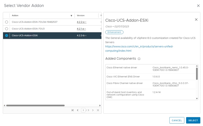
Step 12. Do not select a Firmware and Drivers Addon.
Step 13. To the right of Components, click Show details. Click ADD COMPONENTS.
Step 14. In the Add Components window, click the checkbox to select the NetApp NAS VAAI Module for ESX Server and click SELECT.
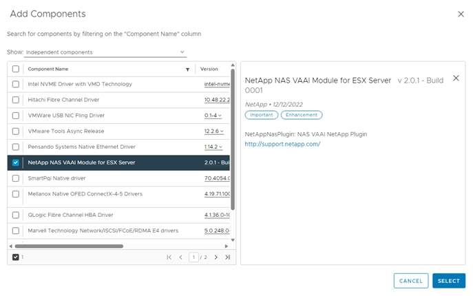
Step 15. Click ADD COMPONENTS. Navigate to and use the checkbox to select Out-of-band host inventory and network configuration using Cisco CIMC. Click SELECT.
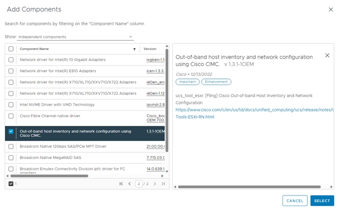
Step 16. The image selection is now complete. Click SAVE to save the image.
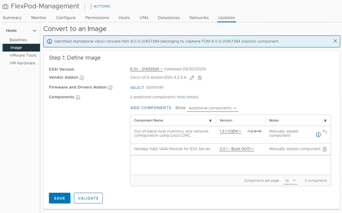
Step 17. Click FINISH IMAGE SETUP and then click YES, FINISH IMAGE SETUP.
Step 18. vCenter will complete an Image Compliance Check and all servers should be out of compliance because of the updated VMware ESXi version. You can click REMEDIATE ALL followed by START REMEDIATION and the servers will be put in Maintenance Mode, upgraded, and brought into compliance one at a time without affecting running VMs. This process will take time depending on the size of the cluster. Once all hosts have been remediated, they should all be compliant with the image.
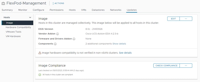
Step 19. The image built in this process can be exported both to a bootable ISO to install or upgrade additional ESXi hosts and to a JSON file to set up other ESXi clusters. To create a bootable ISO, under Inventory select the FlexPod-Management cluster, select the Updates tab, and click … ![]() on the right. Select Export. In the Export Image window, select ISO and click EXPORT. The ISO will be downloaded to your downloads folder. You can rename the image to a more user-friendly name.
on the right. Select Export. In the Export Image window, select ISO and click EXPORT. The ISO will be downloaded to your downloads folder. You can rename the image to a more user-friendly name.
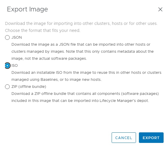
Step 20. To export a JSON file, in the Export Image window select JSON and click EXPORT. A JSON file will be downloaded to your Downloads folder. This file can be imported into another ESXi cluster to manage that cluster with this same ESXi image.
Step 21. The standalone Nexus Dashboard host can be upgraded by using the exported ISO. You will need to shutdown the Nexus Dashboard VM (by right-clicking the VM and selecting Power > Shut Down Guest OS) and then put the Nexus Dashboard ESXi host in Maintenance Mode once the Nexus Dashboard VM has shutdown. Go to Cisco USC Manager and launch a KVM Console for this host. Use the Virtual Media tab to map the downloaded ISO and the use the Power tab to Reset System. When the ESXi Installer has booted follow the prompts to upgrade the host. When the upgrade process is complete, reboot the host. When the host has reconnected to vCenter, Exit Maintenance Mode, and Power On the Nexus Dashboard VM.
Active IQ Unified Manager User Configuration
Procedure 1. Add Local Users to Active IQ Unified Manager
Step 1. Go to Settings > General section and click Users.
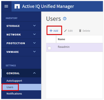
Step 2. Click + Add and complete the requested information:
a. Select Local User for the Type.
b. Enter a username and password.
c. Add the user’s email address.
d. Select the appropriate role for the new user.
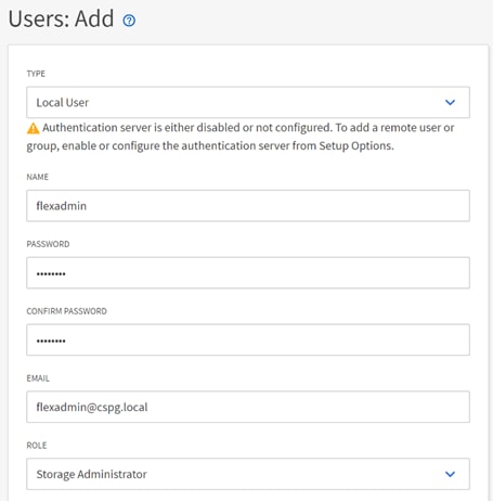
Step 3. Click SAVE to finish adding the new user.
Procedure 2. Configure Remote Authentication
Simplify user management and authentication for Active IQ Unified Manager by integrating it with Microsoft Active Directory.
Note: You must be logged on as the maintenance user created during the installation or another user with Application Administrator privileges to configure remote authentication.
Step 1. Go to General and select Remote Authentication.
Step 2. Select the option to enable Remote Authentication and define a remote user or remote group.
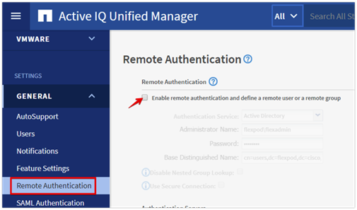
Step 3. Select Active Directory from the authentication service list.
Step 4. Enter the Active Directory service account name and password. The account name can be in the format of domain\user or user@domain.
Step 5. Enter the base DN where your Active Directory users reside.
Step 6. If Active Directory LDAP communications are protected via SSL enable the Use Secure Connection option.
Step 7. Add one or more Active Directory domain controllers by clicking Add and entering the IP or FQDN of the domain controller.
Step 8. Click Save to enable the configuration.
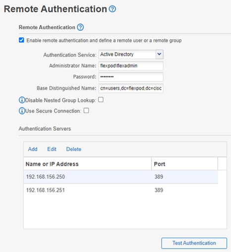
Step 9. Click Test Authentication and enter an Active Directory username and password to test authentication with the Active Directory authentication servers. Click Start.
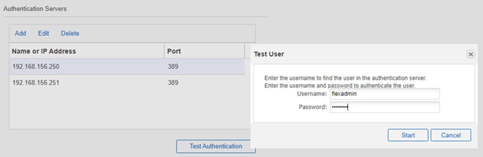
A result message displays indicating authentication was successful:
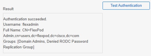
Procedure 3. Add a Remote User to Active IQ Unified Manager
Step 1. Navigate to the General section and select Users.
Step 2. Click Add and select Remote User from the Type drop-down list.
Step 3. Enter the following information into the form:
a. The username of the Active Directory user.
b. Email address of the user.
c. Select the appropriate role (Operator / Storage Administrator / Application Administrator) for the user.
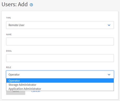
Step 4. Click Save to add the remote user to Active IQ Unified Manager.
Note: Please review the Active IQ Unified Manager documentation page for the definitions of the various user roles:
Active IQ Unified Manager vCenter Configuration
Active IQ Unified Manager provides visibility into vCenter and the virtual machines running inside the datastores backed by ONTAP storage. Virtual machines and storage are monitored to enable quick identification of performance issues within the various components of the virtual infrastructure stack.
Note: Before adding vCenter into Active IQ Unified Manager, the log level of the vCenter server must be changed.
Procedure 1. Configure Active IQ Unified Manager vCenter
Step 1. In the vSphere client go to Menu > VMs and Templates and select the vCenter instance from the top of the object tree.
Step 2. Click the Configure tab, expand Settings, and select General.
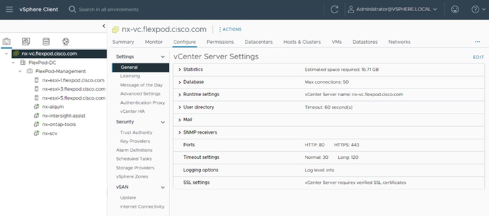
Step 3. Click EDIT.
Step 4. In the pop-up window under Statistics, locate the 5 minutes Interval Duration row and change the setting to Level 3 under the Statistics Level column.
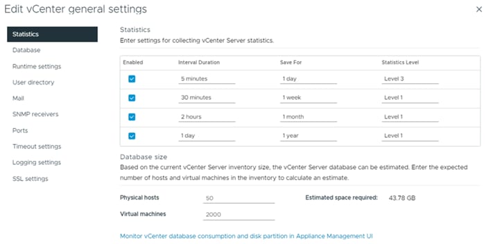
Step 5. Click SAVE.
Step 6. Switch to the Active IQ Unified Manager and navigate to the VMware section located under Inventory.
Step 7. Expand VMware and select vCenter.
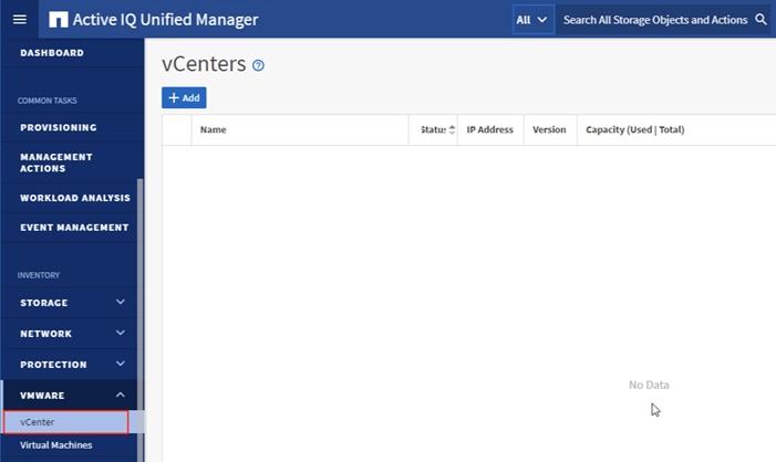
Step 8. Click Add.
Step 9. Enter the VMware vCenter server details and click Save.
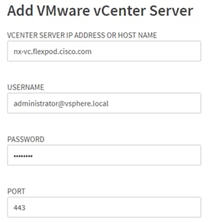
Step 10. A dialog box will appear asking to authorize the certificate. Click Yes to accept the certificate and add the vCenter server.
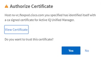
Note: It may take up to 15 minutes to discover vCenter. Performance data can take up to an hour to become available.
Procedure 2. View Virtual Machine Inventory
The virtual machine inventory is automatically added to Active IQ Unified Manager during discovery of the vCenter server. Virtual machines can be viewed in a hierarchical display detailing storage capacity, IOPS and latency for each component in the virtual infrastructure to troubleshoot the source of any performance related issues.
Step 1. Log into NetApp Active IQ Unified Manager.
Step 2. Navigate to the VMware section located under Inventory, expand the section, and click Virtual Machines.
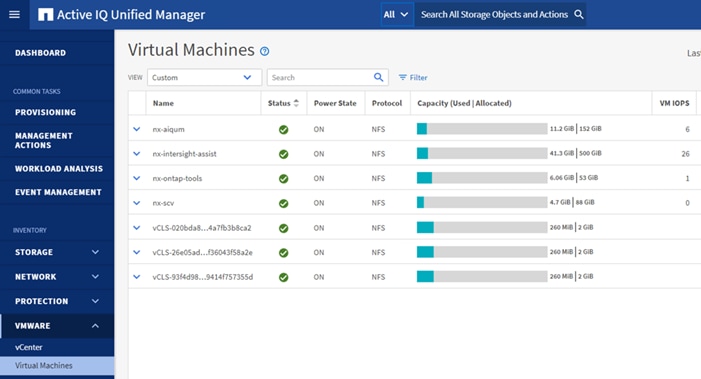
Step 3. Select a VM and click the blue caret to expose the topology view. Review the compute, network, and storage components and their associated IOPS and latency statistics.
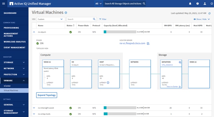
Step 4. Click Expand Topology to see the entire hierarchy of the virtual machine and its virtual disks as it is connected through the virtual infrastructure stack. The VM components are mapped from vSphere and compute through the network to the storage.
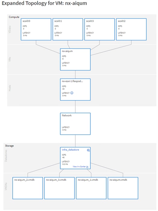
NetApp Active IQ is a data-driven service that leverages artificial intelligence and machine learning to provide analytics and actionable intelligence for ONTAP storage systems. Active IQ uses AutoSupport data to deliver proactive guidance and best practices recommendations to optimize storage performance and minimize risk. Additional Active IQ documentation is available on the Active IQ Documentation Resources web page.
Note: Active IQ is automatically enabled when AutoSupport is configured on the NetApp ONTAP storage controllers.
Procedure 1. Configure NetApp Active IQ
Step 1. Navigate to the Active IQ portal at https://activeiq.netapp.com/.
Step 2. Login with NetApp support account ID.
Step 3. At the Welcome screen enter the cluster name or one of controller serial numbers in the search box. Active IQ will automatically begin searching for the cluster and display results below:
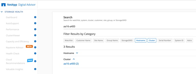
Step 4. Click the <cluster name> (for example, aa02-a800) to launch the dashboard for this cluster.
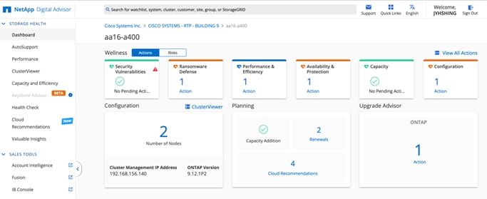
Procedure 2. Add a Watchlist to the Digital Advisor Dashboard
The Active IQ Digital advisor provides a summary dashboard and system wellness score based on the health and risks that Active IQ has identified. The dashboard provides a quick way to identify and get proactive recommendations on how to mitigate risks in the storage environment including links to technical reports and mitigation plans. This procedure details the steps to create a watchlist and launch Digital advisor dashboard for the watchlist.
Step 1. Click GENERAL > Watchlists.
Step 2. Enter a name for the watchlist.
Step 3. Select the radio button to add systems by serial number and enter the cluster serial numbers to the watchlist.
Step 4. Check the box for Make this my default watchlist if desired.
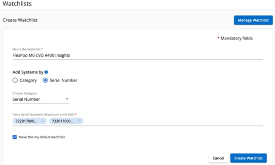
Step 5. Click Create Watchlist.
Step 6. Click GENERAL > Watchlists in the left menu bar again to list the watchlist created.
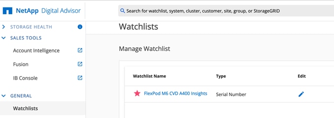
Step 7. Click the blue Watchlist Name to launch the specific watchlist in Digital Advisor Dashboard.
Step 8. Review the dashboard to learn more about any recommended actions or risks.
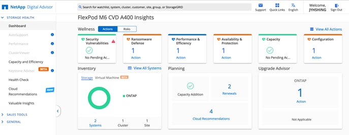
Step 9. Switch between the Actions and Risks tabs to view the risks by category or a list of all risks with their impact and links to corrective actions.
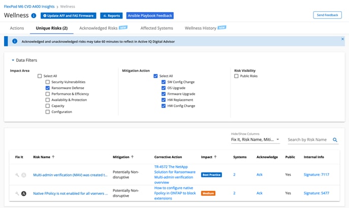
Step 10. Click the links in the Corrective Action column to read the best practice information or knowledge base article about how to remediate the risk.
Note: Additional tutorials and video walk-throughs of Active IQ features can be viewed here: https://docs.netapp.com/us-en/active-iq/
Procedure 1. Cisco Nexus and MDS Backups
The configuration of the Cisco Nexus 9000 and Cisco MDS 9132T switches can be backed up manually at any time with the copy command, but automated backups can be enabled using the NX-OS feature scheduler.
An example of setting up automated configuration backups of one of the NX-OS switches is shown below:
config t
feature scheduler
scheduler logfile size 1024
scheduler job name backup-cfg
copy running-config tftp://<server-ip>/$(SWITCHNAME)-cfg.$(TIMESTAMP) vrf management
exit
scheduler schedule name daily
job name backup-cfg
time daily 2:00
end
Note: Using “vrf management” in the copy command is only needed when Mgmt0 interface is part of VRF management. “vrf management is not needed in Cisco MDS switches.
Step 1. Verify the scheduler job has been correctly setup using following command(s):
show scheduler job
Job Name: backup-cfg
--------------------
copy running-config tftp://10.1.156.150/$(SWITCHNAME)-cfg.$(TIMESTAMP) vrf management
==============================================================================
show scheduler schedule
Schedule Name : daily
---------------------------
User Name : admin
Schedule Type : Run every day at 2 Hrs 0 Mins
Last Execution Time : Yet to be executed
-----------------------------------------------
Job Name Last Execution Status
-----------------------------------------------
backup-cfg -NA-
==============================================================================
The documentation for the feature scheduler can be found here: https://www.cisco.com/c/en/us/td/docs/dcn/nx-os/nexus9000/102x/configuration/system-management/cisco-nexus-9000-series-nx-os-system-management-configuration-guide-102x/m-configuring-the-scheduler-10x.html
Procedure 2. NetApp ONTAP Configuration Backup
The configuration backup files of the NetApp ONTAP cluster and nodes are automatically created according to the following schedules:
● Every 8 hours
● Daily
● Weekly
At each of these times, a node configuration backup file is created on each healthy node in the cluster. All of these node configuration backup files are then collected in a single cluster configuration backup file along with the replicated cluster configuration and saved on one or more nodes in the cluster.
An example of viewing the ONTAP cluster configuration backup files is shown below:
AA16-A400::> set advanced
Warning: These advanced commands are potentially dangerous; use them only when directed to do so by NetApp personnel.
Do you want to continue? {y|n}: y
AA16-A400::*> row 0
(rows)
AA16-A400::*> system configuration backup show
Node Backup Name Time Size
--------- ----------------------------------------- ------------------ -----
AA16-A400-01 AA16-A400.8hour.2023-08-31.18_15_00.7z 08/31 18:15:00 34.60MB
AA16-A400-01 AA16-A400.8hour.2023-09-01.02_15_00.7z 09/01 02:15:00 35.65MB
AA16-A400-01 AA16-A400.8hour.2023-09-01.10_15_00.7z 09/01 10:15:00 36.05MB
AA16-A400-01 AA16-A400.daily.2023-08-31.00_10_01.7z 08/31 00:10:01 34.87MB
AA16-A400-01 AA16-A400.daily.2023-09-01.00_10_01.7z 09/01 00:10:01 35.09MB
AA16-A400-01 AA16-A400.weekly.2023-08-27.00_15_00.7z 08/27 00:15:00 23.50MB
AA16-A400-02 AA16-A400.8hour.2023-09-01.02_15_00.7z 09/01 02:15:00 35.65MB
AA16-A400-02 AA16-A400.8hour.2023-09-01.10_15_00.7z 09/01 10:15:00 36.05MB
AA16-A400-02 AA16-A400.daily.2023-08-30.00_10_00.7z 08/30 00:10:00 32.69MB
AA16-A400-02 AA16-A400.daily.2023-08-31.00_10_01.7z 08/31 00:10:01 34.87MB
AA16-A400-02 AA16-A400.daily.2023-09-01.00_10_01.7z 09/01 00:10:01 35.09MB
AA16-A400-02 AA16-A400.weekly.2023-08-27.00_15_00.7z 08/27 00:15:00 23.50MB
12 entries were displayed.
AA16-A400::*> set admin
AA16-A400::>
You can use the system configuration backup settings commands to manage configuration backup schedules and specify a remote URL (HTTP, HTTPS, FTP, FTPS, or TFTP ) where the configuration backup files will be uploaded in addition to the default locations in the cluster.
An example of setting up an automated ONTAP cluster configuration backup upload destination using TFTP is shown below:
AA16-A400::> set advanced
Warning: These advanced commands are potentially dangerous; use them only when directed to do so by NetApp personnel.
Do you want to continue? {y|n}: y
AA16-A400::*> system configuration backup setting modify -destination tftp://10.1.156.150/ONTAP
AA16-A400::*> system configuration backup setting show
Backup Destination URL Username
-------------------------------------------------- -------------
tftp://10.1.156.150/ONTAP
AA16-A400::*> set admin
AA16-A400::>
Procedure 3. VMware VCSA Backup
Note: Basic scheduled backup for the vCenter Server Appliance is available within the native capabilities of the VCSA.
Step 1. Connect to the VCSA Console at https://<VCSA IP>:5480.
Step 2. Log in as root.
Step 3. Click Backup in the list to open the Backup Schedule Dialogue.
Step 4. To the right of Backup Schedule, click CONFIGURE.
Step 5. Specify the following:
a. The Backup location with the protocol to use (FTPS,HTTPS,SFTP,FTP,NFS,SMB, and HTTP)
b. The Username and Password. For the NFS (NFS3) example captured below, the username is root and use a random password because NFSv3 sys security was configured.
c. The Number of backups to retain.
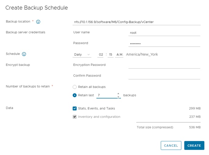
Step 6. Click CREATE.
The Backup Schedule Status should now show Activated.
Step 7. To test the backup setup, select BACKUP NOW and select “Use backup location and user name from backup schedule” to test the backup location. Fill in the password, add an optional Description and click START.
Step 8. Restoration can be initiated with the backed-up files using the Restore function of the VCSA 8.0 Installer.
For comments and suggestions about this guide and related guides, join the discussion on Cisco Community at https://cs.co/en-cvds.
CVD Program
ALL DESIGNS, SPECIFICATIONS, STATEMENTS, INFORMATION, AND RECOMMENDATIONS (COLLECTIVELY, "DESIGNS") IN THIS MANUAL ARE PRESENTED "AS IS," WITH ALL FAULTS. CISCO AND ITS SUPPLIERS DISCLAIM ALL WARRANTIES, INCLUDING, WITHOUT LIMITATION, THE WARRANTY OF MERCHANTABILITY, FITNESS FOR A PARTICULAR PURPOSE AND NONINFRINGEMENT OR ARISING FROM A COURSE OF DEALING, USAGE, OR TRADE PRACTICE. IN NO EVENT SHALL CISCO OR ITS SUPPLIERS BE LIABLE FOR ANY INDIRECT, SPECIAL, CONSEQUENTIAL, OR INCIDENTAL DAMAGES, INCLUDING, WITHOUT LIMITATION, LOST PROFITS OR LOSS OR DAMAGE TO DATA ARISING OUT OF THE USE OR INABILITY TO USE THE DESIGNS, EVEN IF CISCO OR ITS SUPPLIERS HAVE BEEN ADVISED OF THE POSSIBILITY OF SUCH DAMAGES.
THE DESIGNS ARE SUBJECT TO CHANGE WITHOUT NOTICE. USERS ARE SOLELY RESPONSIBLE FOR THEIR APPLICATION OF THE DESIGNS. THE DESIGNS DO NOT CONSTITUTE THE TECHNICAL OR OTHER PROFESSIONAL ADVICE OF CISCO, ITS SUPPLIERS OR PARTNERS. USERS SHOULD CONSULT THEIR OWN TECHNICAL ADVISORS BEFORE IMPLE-MENTING THE DESIGNS. RESULTS MAY VARY DEPENDING ON FACTORS NOT TESTED BY CISCO.
CCDE, CCENT, Cisco Eos, Cisco Lumin, Cisco Nexus, Cisco StadiumVision, Cisco TelePresence, Cisco WebEx, the Cisco logo, DCE, and Welcome to the Human Network are trademarks; Changing the Way We Work, Live, Play, and Learn and Cisco Store are service marks; and Access Registrar, Aironet, AsyncOS, Bringing the Meeting To You, Catalyst, CCDA, CCDP, CCIE, CCIP, CCNA, CCNP, CCSP, CCVP, Cisco, the Cisco Certified Internetwork Expert logo, Cisco IOS, Cisco Press, Cisco Systems, Cisco Systems Capital, the Cisco Systems logo, Cisco Unified Computing System (Cisco UCS), Cisco UCS B-Series Blade Servers, Cisco UCS C-Series Rack Servers, Cisco UCS S-Series Storage Servers, Cisco UCS X-Series, Cisco UCS Manager, Cisco UCS Management Software, Cisco Unified Fabric, Cisco Application Centric Infrastructure, Cisco Nexus 9000 Series, Cisco Nexus 7000 Series. Cisco Prime Data Center Network Manager, Cisco NX-OS Software, Cisco MDS Series, Cisco Unity, Collaboration Without Limitation, EtherFast, EtherSwitch, Event Center, Fast Step, Follow Me Browsing, FormShare, GigaDrive, HomeLink, Internet Quotient, IOS, iPhone, iQuick Study, LightStream, Linksys, MediaTone, MeetingPlace, MeetingPlace Chime Sound, MGX, Networkers, Networking Academy, Network Registrar, PCNow, PIX, PowerPanels, ProConnect, ScriptShare, SenderBase, SMARTnet, Spectrum Expert, StackWise, The Fastest Way to Increase Your Internet Quotient, TransPath, WebEx, and the WebEx logo are registered trade-marks of Cisco Systems, Inc. and/or its affiliates in the United States and certain other countries. (LDW_P6)
All other trademarks mentioned in this document or website are the property of their respective owners. The use of the word partner does not imply a partnership relationship between Cisco and any other company. (0809R)