FlexPod Datacenter with NetApp All Flash FAS, Cisco Application Centric Infrastructure, and VMware vSphere
Available Languages

FlexPod Datacenter with NetApp All Flash FAS, Cisco Application Centric Infrastructure, and VMware vSphere
Deployment Guide for FlexPod with NetApp All Flash FAS and Cisco Application Centric Infrastructure and VMware vSphere 5.5U2
Last Updated: August 25, 2015

The CVD program consists of systems and solutions designed, tested, and documented to facilitate faster, more reliable, and more predictable customer deployments. For more information visit
http://www.cisco.com/go/designzone.
ALL DESIGNS, SPECIFICATIONS, STATEMENTS, INFORMATION, AND RECOMMENDATIONS (COLLECTIVELY, "DESIGNS") IN THIS MANUAL ARE PRESENTED "AS IS," WITH ALL FAULTS. CISCO AND ITS SUPPLIERS DISCLAIM ALL WARRANTIES, INCLUDING, WITHOUT LIMITATION, THE WARRANTY OF MERCHANTABILITY, FITNESS FOR A PARTICULAR PURPOSE AND NONINFRINGEMENT OR ARISING FROM A COURSE OF DEALING, USAGE, OR TRADE PRACTICE. IN NO EVENT SHALL CISCO OR ITS SUPPLIERS BE LIABLE FOR ANY INDIRECT, SPECIAL, CONSEQUENTIAL, OR INCIDENTAL DAMAGES, INCLUDING, WITHOUT LIMITATION, LOST PROFITS OR LOSS OR DAMAGE TO DATA ARISING OUT OF THE USE OR INABILITY TO USE THE DESIGNS, EVEN IF CISCO OR ITS SUPPLIERS HAVE BEEN ADVISED OF THE POSSIBILITY OF SUCH DAMAGES.
THE DESIGNS ARE SUBJECT TO CHANGE WITHOUT NOTICE. USERS ARE SOLELY RESPONSIBLE FOR THEIR APPLICATION OF THE DESIGNS. THE DESIGNS DO NOT CONSTITUTE THE TECHNICAL OR OTHER PROFESSIONAL ADVICE OF CISCO, ITS SUPPLIERS OR PARTNERS. USERS SHOULD CONSULT THEIR OWN TECHNICAL ADVISORS BEFORE IMPLEMENTING THE DESIGNS. RESULTS MAY VARY DEPENDING ON FACTORS NOT TESTED BY CISCO.
CCDE, CCENT, Cisco Eos, Cisco Lumin, Cisco Nexus, Cisco StadiumVision, Cisco TelePresence, Cisco WebEx, the Cisco logo, DCE, and Welcome to the Human Network are trademarks; Changing the Way We Work, Live, Play, and Learn and Cisco Store are service marks; and Access Registrar, Aironet, AsyncOS, Bringing the Meeting To You, Catalyst, CCDA, CCDP, CCIE, CCIP, CCNA, CCNP, CCSP, CCVP, Cisco, the Cisco Certified Internetwork Expert logo, Cisco IOS, Cisco Press, Cisco Systems, Cisco Systems Capital, the Cisco Systems logo, Cisco Unity, Collaboration Without Limitation, EtherFast, EtherSwitch, Event Center, Fast Step, Follow Me Browsing, FormShare, GigaDrive, HomeLink, Internet Quotient, IOS, iPhone, iQuick Study, IronPort, the IronPort logo, LightStream, Linksys, MediaTone, MeetingPlace, MeetingPlace Chime Sound, MGX, Networkers, Networking Academy, Network Registrar, PCNow, PIX, PowerPanels, ProConnect, ScriptShare, SenderBase, SMARTnet, Spectrum Expert, StackWise, The Fastest Way to Increase Your Internet Quotient, TransPath, WebEx, and the WebEx logo are registered trademarks of Cisco Systems, Inc. and/or its affiliates in the United States and certain other countries.
All other trademarks mentioned in this document or website are the property of their respective owners. The use of the word partner does not imply a partnership relationship between Cisco and any other company. (0809R)
© 2015 Cisco Systems, Inc. All rights reserved.
Deployment Hardware and Software
Complete the Configuration Worksheet
Configure Clustered Data ONTAP Nodes
Set Onboard UTA2 Ports Personality
Set Auto-Revert on Cluster Management
Set Up Management Broadcast Domain
Set Up Service Processor Network Interface
Disable Flow Control on UTA2 Ports
Enable Cisco Discovery Protocol
Create Jumbo Frame MTU Broadcast Domains in Clustered Data ONTAP
Create Storage Virtual Machine
Create Load-Sharing Mirrors of SVM Root Volume
Add Infrastructure SVM Administrator
Perform Initial Setup of Cisco UCS 6248 Fabric Interconnect for FlexPod Environments
Upgrade Cisco UCS Manager Software to Version 2.2(3d)
Add Block of IP Addresses for KVM Access
Enable Server and Uplink Ports
Acknowledge Cisco UCS Chassis and FEX
Create Uplink Port Channels to Cisco Nexus Switches
Create IQN Pools for iSCSI Boot
Create IP Pools for iSCSI Boot
Set Jumbo Frames in Cisco UCS Fabric
Create Local Disk Configuration Policy (Optional)
Create Network Control Policy for Cisco Discovery Protocol
Create Server Pool Qualification Policy (Optional)
Create vNIC/vHBA Placement Policy for Virtual Machine Infrastructure Hosts
Update Default Maintenance Policy
Create Service Profile Template
Add More Servers to FlexPod Unit
ACI Infrastructure Configuration
Cisco APIC Initial Configuration Setup
Cisco ACI – Defining Fabric Access Policies
Cisco ACI – Creating vPC for Cisco UCS Fabric Interconnect A
Cisco ACI – Creating vPC for UCS Fabric Interconnect B
Cisco ACI – Creating vPC for NetApp Controller 1
Cisco ACI – Creating vPC for NetApp Controller 2
Cisco ACI – Deploying Infrastructure (Foundation) Tenant
Storage Configuration – SAN Boot
Clustered Data ONTAP SAN Boot Storage Setup
Download Cisco Custom Image for ESXi 5.5.0 U2
Log in to Cisco UCS 6200 Fabric Interconnect
Set Up VMware ESXi Installation
Set Up Management Networking for ESXi Hosts
Download VMware vSphere Client
Download VMware vSphere CLI 5.5
Log in to VMware ESXi Hosts by Using VMware vSphere Client
Set Up VMkernel Ports and Virtual Switch
Install VMware Drivers for the Cisco Virtual Interface Card (VIC)
Install Microsoft SQL Server 2012 SP1
Build and Set Up VMware vCenter Virtual Machine
Adding the AD Account to Administrator Group
Set Up vCenter Center with a Datacenter, Cluster, DRS and HA
ESXi Dump Collector Setup for iSCSI-Booted Hosts
Cisco ACI – Virtual Machine Manager
Defining VMware Distributed Switch policies
VMware Distributed Switch - Deployment Validation
Adding Hosts to VMware Distributed Switch
vMotion - Application Profile Creation
Cisco ACI – Deploying a Tenant
Application Specific SVM Creation
Broadcast Domains in Clustered Data ONTAP
Storage Virtual Machine (Vserver)
Create Load Sharing Mirror of Vserver Root Volume in Clustered Data ONTAP
iSCSI Service in Clustered Data ONTAP
HTTPS Access in Clustered Data ONTAP
FlexVol in Clustered Data ONTAP
Deduplication in Clustered Data ONTAP
NFS LIF in Clustered Data ONTAP
iSCSI LIF in Clustered Data ONTAP (Optional)
Add App-A Vserver Administrator
Application Tenant Creation on APIC
3-Tier App - Application Profile Creation and Adding EPG for Web Tier
Port-Group Deployment Validation
Modifying the Storage (NetApp) Physical Domain VLANs
NFS - Application Profile Creation
iSCSI Application Profile Creation (Optional)
Defining NFS VMKernel Port and Mounting the Datastore
Defining EPGs for additional Application Tiers (Optional)
Enabling Communication Between Application Tiers
Cisco ACI – Accessing Common Services
Configuring ACI for Management Switch
Configuring the Management Switch
Common Management - Application Profile Creation
Consuming the Common Contract in Application EPGs
Cisco ACI – Accessing SVM Management Interface from Application Virtual Machines (Optional)
SVM-Access - Application Profile Creation
EPG and Contract Configuration
Consuming the SVM Management Contract in an Application Tier (Web)
Cisco ACI – Connecting to Existing Infrastructure
Configuring the Nexus 7000 for ACI Connectivity (Sample)
Configuring ACI for External Routed Domain
Configuring Multi-Protocol BGP on Spines
FlexPod Management Tools Setup
NetApp Virtual Storage Console (VSC) 6.0 Deployment Procedure
VSC 6.0 Pre-installation Considerations
Register VSC with vCenter Server
Discover and Add Storage Resources
Optimal Storage Settings for ESXi Hosts
NetApp VASA Provider for Clustered Data ONTAP Deployment Procedure
Registering VASA Provider for Clustered Data ONTAP with VSC
OnCommand Unified Manager OVF Deployment
OnCommand Unified Manager Basic Setup
OnCommand Performance Manager 1.1
OnCommand Performance Manager OVF Deployment
OnCommand Performance Manager Basic Setup
Link OnCommand Performance Manager to OnCommand Unified Manager
NetApp NFS Plug-In 1.0.21 for VMware VAAI
Enable VMware vStorage for NFS in Clustered Data ONTAP
Install NetApp NFS Plug-In for VMware VAAI
Appendix A - Deploying Direct Connect FCoE
Add FCP as an Allowed Protocol in Infrastructure SVM
FCP Service in Clustered Data ONTAP
Create LUNs in Clustered Data ONTAP
FCoE LIF in Clustered Data ONTAP
Place Cisco UCS Fabric Interconnects in Fiber Channel Switching Mode
Create a WWNN Pool for FCoE Boot
Assign VSANs to FCoE Storage Ports
Create Storage Connection Policies for FCoE Zoning
Create Service Profile Template
Clustered Data ONTAP SAN Boot Storage Setup
Cisco® Validated Designs include systems and solutions that are designed, tested, and documented to facilitate and improve customer deployments. These designs incorporate a wide range of technologies and products into a portfolio of solutions that have been developed to address the business needs of customers. Cisco and NetApp have partnered to deliver FlexPod, which serves as the foundation for a variety of workloads and enables efficient architectural designs that are based on customer requirements. A FlexPod solution is a validated approach for deploying Cisco and NetApp technologies as a shared cloud infrastructure.
This document describes the Cisco and NetApp® FlexPod Datacenter with NetApp All Flash FAS (AFF), Cisco Application Centric Infrastructure (ACI), and VMware vSphere 5.5 Update 2. FlexPod Datacenter with NetApp AFF and Cisco ACI is a predesigned, best-practice data center architecture built on the Cisco Unified Computing System (UCS), the Cisco Nexus® 9000 family of switches, and NetApp AFF.
Introduction
Industry trends indicate a vast data center transformation toward shared infrastructure and cloud computing. Business agility requires application agility, so IT teams need to provision applications in hours instead of months. Resources need to scale up (or down) in minutes, not hours.
To simplify the evolution to a shared cloud infrastructure based on an application driven policy model, Cisco and NetApp have developed the solution called FlexPod Datacenter with NetApp AFF and Cisco ACI. Cisco ACI provides a holistic architecture with centralized automation and policy-driven application profiles that delivers software flexibility with hardware performance. NetApp All Flash FAS addresses enterprise storage requirements with high performance, superior flexibility, and best-in-class data management.
Audience
The audience for this document includes, but is not limited to; sales engineers, field consultants, professional services, IT managers, partner engineers, and customers who want to take advantage of an infrastructure built to deliver IT efficiency and enable IT innovation.
Purpose of this Document
This document provides a step-by-step configuration and implementation guide for the FlexPod Datacenter with NetApp AFF and Cisco ACI solution. For the design decisions and technology discussion of the solution, please refer to FlexPod Datacenter with NetApp All Flash FAS, Cisco Nexus 9000 ACI, and VMware vSphere Design Guide:
What’s New?
The following design elements distinguish this version of FlexPod from previous non-ACI FlexPod models:
· Validation of the Cisco ACI with a NetApp All-Flash FAS storage array
· Support for the Cisco UCS 2.2 release and Cisco UCS B200-M4 servers
· Support for the latest release of NetApp Data ONTAP® 8.3
· An IP-based storage design supporting both NAS datastores and iSCSI based SAN LUNs
· Support for direct attached Fiber Chanel storage access for boot LUNs
· Application design guidance for multi-tiered applications using Cisco ACI application profiles and policies
Architecture
FlexPod is a defined set of hardware and software that serves as an integrated foundation for both virtualized and non-virtualized solutions. VMware vSphere® built on FlexPod includes NetApp storage, NetApp Data ONTAP, NetApp All Flash FAS, Cisco Nexus® networking, the Cisco Unified Computing System (Cisco UCS®), and VMware vSphere software in a single package. The design is flexible enough that the networking, computing, and storage can fit in one data center rack or be deployed according to a customer's data center design. Port density enables the networking components to accommodate multiple configurations of this kind.
One benefit of the FlexPod architecture is the ability to customize or "flex" the environment to suit a customer's requirements. A FlexPod can easily be scaled as requirements and demand change. The unit can be scaled both up (adding resources to a FlexPod unit) and out (adding more FlexPod units). The reference architecture detailed in this document highlights the resiliency, cost benefit, and ease of deployment of an IP-based storage solution. A storage system capable of serving multiple protocols across a single interface allows for customer choice and investment protection because it truly is a wire-once architecture.
Figure 1 shows the VMware vSphere built on FlexPod components and the network connections for a configuration with IP-based storage. This design uses the Cisco Nexus 9000, Cisco Nexus 2232PP FEX, and Cisco UCS C-Series and B-Series servers and the NetApp AFF family of storage controllers connected in a highly available modular design. This infrastructure is deployed to provide iSCSI-booted hosts with file-level and block-level access to shared storage. The reference architecture reinforces the "wire-once" strategy, because as additional storage is added to the architecture, no re-cabling is required from the hosts to the Cisco UCS fabric interconnect.
The ACI switching architecture is laid out in a leaf-and-spine topology where every leaf connects to every spine using 40G Ethernet interface(s). The software controller, APIC, is delivered as an appliance and three or more such appliances form a cluster for high availability and enhanced performance.
Physical Topology
Figure 1 illustrates the physical architecture.
Figure 1 FlexPod Design with Cisco ACI and NetApp Data ONTAP
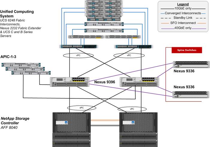
The reference hardware configuration includes:
· Two Cisco Nexus 9396 switches
· Two Cisco Nexus 2232 fabric extenders
· Two Cisco UCS 6248UP fabric interconnects
· One NetApp AFF8040 (HA pair) running clustered Data ONTAP with Disk shelves and Solid State Drives (SSD)
While not included in the FlexPod BOM, Cisco ACI spines and APIC controllers are integral part of Cisco ACI design. The following components were used in the validation efforts:
· Three APIC Controllers
· Two Cisco Nexus 9336 based spines
For server virtualization, the deployment includes VMware vSphere. Although this is the base design, each of the components can be scaled easily to support specific business requirements. For example, more (or different) servers or even blade chassis can be deployed to increase compute capacity, additional disk shelves can be deployed to improve I/O capability and throughput, and special hardware or software features can be added to introduce new features. This document guides you through the low-level steps for deploying the base architecture, as shown in Figure 1. These procedures cover everything from physical cabling to network, compute and storage device configurations.
Software Revisions
Table 1 lists the software revisions for this solution.
| Layer |
Device |
Image |
Comments |
| Compute |
Cisco UCS Fabric Interconnects 6200 Series, UCS B-200 M4, UCS C-220 M4 |
2.2(3d) |
Includes the Cisco UCS-IOM 2208XP, Cisco UCS Manager, UCS VIC 1240 and UCS VIC 1340 |
|
|
Cisco eNIC |
2.1.2.62 |
|
|
|
Cisco fNIC |
1.6.0.12b |
|
| Network |
Cisco APIC |
1.0(4h)* |
|
|
|
Cisco Nexus 9000 iNX-OS |
11.0(4h)* |
|
| Storage |
NetApp AFF 8040 |
Data ONTAP 8.3 |
|
| Software |
VMware vSphere ESXi |
5.5u2 |
|
|
|
VMware vCenter |
5.5u2 |
|
|
|
OnCommand Unified Manager for clustered Data ONTAP |
6.2 |
|
|
|
NetApp Virtual Storage Console (VSC) |
6.0 |
|
|
|
OnCommand Performance Manager |
1.1 |
|
* Customers should always use the latest ACI software after consulting with their account team. The APIC screen captures in this Deployment Guide were captured in an earlier version and might be slightly different.
Configuration Guidelines
This document provides details for configuring a fully redundant, highly available configuration for a FlexPod unit with clustered Data ONTAP storage. Therefore, reference is made to which component is being configured with each step, either 01 or 02 or A and B. For example, node01 and node02 are used to identify the two NetApp storage controllers that are provisioned with this document, and Cisco Nexus A or Cisco Nexus B identifies the pair of Cisco Nexus switches that are configured. The Cisco UCS fabric interconnects are similarly configured. Additionally, this document details the steps for provisioning multiple Cisco UCS hosts, and these are identified sequentially: VM-Host-Infra-01, VM-Host-Infra-02, and so on. Finally, to indicate that you should include information pertinent to your environment in a given step, <text> appears as part of the command structure. See the following example for the network port vlan create command:
Usage:
network port vlan create ?
[-node] <nodename> Node
{ [-vlan-name] {<netport>|<ifgrp>} VLAN Name
| -port {<netport>|<ifgrp>} Associated Network Port
[-vlan-id] <integer> } Network Switch VLAN Identifier
Example:
network port vlan -node <node01> -vlan-name i0a-<vlan id>
This document is intended to enable you to fully configure the customer environment. In this process, various steps require you to insert customer-specific naming conventions, IP addresses, and VLAN schemes, as well as to record appropriate MAC addresses. Table 3 lists the virtual machines (VMs) necessary for deployment as outlined in this guide. Table 2 describe the VLANs necessary for deployment as outlined in this guide.
| VLAN Name |
VLAN Purpose |
ID Used in Validating This Document |
| Out of band Mgmt |
VLAN for out-of-band management interfaces |
3177 |
| Native |
VLAN to which untagged frames are assigned |
2 |
| NFS LIF |
VLAN for NFS LIF (NetApp) traffic |
3170 |
| NFS VMK |
VLAN for NFS VMkernel (Infrastructure ESXi hosts) traffic |
3270 |
| iSCSI-A LIF |
VLAN for Fabric A iSCSI LIF |
901 |
| iSCSI-B LIF |
VLAN for Fabric B iSCSI LIF |
902 |
| iSCSI-A-VMK |
VLAN for iSCSI traffic for fabric A |
911 |
| iSCSI-B-VMK |
VLAN for iSCSI traffic for fabric B |
912 |
| Tenant Traffic |
VLAN Range defined for ACI |
1101-1200 |
Table 3 lists the virtual machines (VMs) necessary for deployment as outlined in this document.
| Virtual Machine Description |
Host Name |
| Active Directory |
|
| vCenter SQL Server database |
|
| vCenter Server |
|
| NetApp Virtual Storage Console (VSC) |
|
| NetApp OnCommand Unified Manager |
|
| OnCommand Performance Manager |
|
Table 4 lists the configuration variables that are used throughout this document. This table can be completed based on the specific site variables and used in implementing the document configuration steps.
Table 4 Configuration Variables
| Variable |
Value |
| <<var_node01_mgmt_ip>> |
Out-of-band management IP for cluster node 01 |
| <<var_node01_mgmt_mask>> |
Out-of-band management network netmask |
| <<var_node01_mgmt_gateway>> |
Out-of-band management network default gateway |
| <<var_url_boot_software>> |
Data ONTAP 8.3 URL; format: http:// |
| <<var_node02_mgmt_ip>> |
Out-of-band management IP for cluster node 02 |
| <<var_node02_mgmt_mask>> |
Out-of-band management network netmask |
| <<var_node02_mgmt_gateway>> |
Out-of-band management network default gateway |
| <<var_clustername>> |
Storage cluster host name |
| <<var_cluster_base_license_key>> |
Cluster base license key |
| <<var_nfs_license>> |
NFS license key |
| <<var_iscsi_license>> |
iSCSI license key |
| <<var_password>> |
Global default administrative password |
| <<var_clustermgmt_ip>> |
In-band management IP for the storage cluster |
| <<var_clustermgmt_mask>> |
Out-of-band management network netmask |
| <<var_clustermgmt_gateway>> |
Out-of-band management network default gateway |
| <<var_dns_domain_name>> |
DNS domain name |
| <<var_nameserver_ip>> |
DNS server IP(s) |
| <<var_node_location>> |
Node location string for each node |
| <<var_node01_sp_ip>> |
Out-of-band cluster node 01 service processor management IP |
| <<var_node01_sp_mask>> |
Out-of-band management network netmask |
| <<var_node01_sp_gateway> |
Out-of-band management network default gateway |
| <<var_node02_sp_ip>> |
Out-of-band cluster node 02 device processor management IP |
| <<var_node02_sp_mask>> |
Out-of-band management network netmask |
| <<var_node02_sp_gateway> |
Out-of-band management network default gateway |
| <<var_node01>> |
Cluster node 01 hostname |
| <<var_node02>> |
Cluster node 02 hostname |
| <<var_num_disks>> |
Number of disks to assign to each storage controller |
| <<var_nfs_vlan_id>> |
Infrastructure NFS VLAN ID for LIF |
| <<var_nfs_vlan_tenant>> |
Tenant NFS VLAN ID for LIF (only required when deploying a tenant) |
| <<var_iscsi_vlan_A_id>> |
Infrastructure iSCSI-A VLAN ID for LIF |
| <<var_iscsi_vlan_B_id>> |
Infrastructure iSCSI-B VLAN ID for LIF |
| <<var_iscsi_vlan_A_tenant>> |
Tenant iSCSI-A VLAN ID for LIF (optional) |
| <<var_iscsi_vlan_B_tenant>> |
Tenant iSCSI-B VLAN ID for LIF (optional) |
| <<var_nfs_vlan_vmk>> |
Infrastructure NFS VLAN ID for VMkernel Port |
| <<var_iscsi_vlan_A_vmk>> |
Infrastructure iSCSI-A VLAN ID for VMkernel Port |
| <<var_iscsi_vlan_B_vmk>> |
Infrastructure iSCSI-B VLAN ID for VMkernel Port |
| <<var_ib_mgmt_vlan_id>> |
In-band management network VLAN ID |
| <<var_oob_mgmt_vlan_id>> |
Out-of-band management network VLAN ID |
| <<var_timezone>> |
FlexPod time zone (for example, America/New_York) |
| <<var_global_ntp_server_ip>> |
NTP server IP address |
| <<var_snmp_contact>> |
Administrator e-mail address |
| <<var_snmp_location>> |
Cluster location string |
| <<var_oncommand_server_fqdn>> |
VSC or OnCommand virtual machine fully qualified domain name (FQDN) |
| <<var_snmp_community>> |
Storage cluster SNMP v1/v2 community name |
| <<var_mailhost>> |
Mail server host name |
| <<var_storage_admin_email>> |
Administrator e-mail address |
| <<var_esxi_host1_nfs_ip>> |
NFS VLAN IP address for VMware ESXi host 1 |
| <<var_esxi_host2_nfs_ip>> |
NFS VLAN IP address for VMware ESXi host 2 |
| <<var_node01_nfs_lif_infra_swap_ip>> |
IP address of Infra Swap |
| <<var_node01_nfs_lif_infra_swap_mask>> |
Subnet Mask of Infra Swap |
| <<var_node02_nfs_lif_infra_datastore_1_ip>> |
IP address of Datastore 1 |
| <<var_node02_nfs_lif_infra_datastore_1_mask>> |
Subnet mask of Datastore 1 |
| <<var_vserver_mgmt_ip>> |
Management IP address for Vserver |
| <<var_vserver_mgmt_mask>> |
Subnet mask for Vserver |
| <<var_routing_group>> |
Routing group for Vserver |
| <<var_vserver_mgmt_gateway>> |
Default Gateway for Vserver |
| <<var_vsadmin_password>> |
Password for VS admin account |
| <<var_ucs_clustername>> |
Cisco UCS Manager cluster host name |
| <<var_ucsa_mgmt_ip>> |
Cisco UCS fabric interconnect (FI) A out-of-band management IP address |
| <<var_ucsa_mgmt_mask>> |
Out-of-band management network netmask |
| <<var_ucsa_mgmt_gateway>> |
Out-of-band management network default gateway |
| <<var_ucsb_mgmt_ip>> |
Cisco UCS FI B out-of-band management IP address |
| <<var_vm_host_infra_01_iqn>> |
IQN of Infra 01 |
| <<var_vm_host_infra_02_iqn>> |
IQN of Infra 02 |
| <<var_vm_host_infra_01_ip>> |
VMware ESXi host 01 out-of-band management IP |
| <<var_vm_host_infra_02_ip>> |
VMware ESXi host 02 out-of-band management IP |
| <<var_nfs_vlan_ip_host_01>> |
ESXi host 1, NFS VLAN IP |
| <<var_nfs_vlan_ip_mask_host_01>> |
ESXi host1, NFS VLAN subnet mask |
| <<var_nfs_vlan_ip_host_02>> |
ESXi host 2, NFS VLAN IP |
| <<var_nfs_vlan_ip_mask_host_02>> |
ESXi host2, NFS VLAN subnet mask |
| <<var_vcenter_server_ip>> |
IP address of the vCenter Server |
| <<var_svm_mgmt_vlan_id>> |
Infrastructure Vserver management VLAN ID |
| <<var_svm_mgmt_vlan_tenant>> |
Tenant Vserver management VLAN ID |
| <<var_nfs_subnet_address>> |
NFS subnet address |
| <<var_node02_nfs_lif_tenant_datastore_1_ip>> |
Tenant Datastore 1 IP address |
| <<var_node02_nfs_lif_tenant_datastore_1_mask>> |
Tenant Datastore 1 Subnet mask |
| <<var_node01_iscsi_lif01a_ip>> |
iSCSI LIF 01a IP address |
| <<var_node01_iscsi_lif01a_mask>> |
iSCSI LIF 01a subnet mask |
| <<var_node01_iscsi_lif01b_ip>> |
iSCSI LIF 01b IP address |
| <<var_node01_iscsi_lif01b_mask>> |
iSCSI LIF 01b subnet mask |
| <<var_node01_iscsi_lif02a_ip>> |
iSCSI LIF 02a IP address |
| <<var_node01_iscsi_lif02a_mask>> |
iSCSI LIF 02a subnet mask |
| <<var_node01_iscsi_lif02b_ip>> |
iSCSI LIF 02b IP address |
| <<var_node01_iscsi_lif02b_mask>> |
iSCSI LIF 02b subnet mask |
| <<var_node01_iscsi_tenant_lif01a_ip>> |
Tenant iSCSI LIF 01a IP address |
| <<var_node01_iscsi_tenant_lif01a_mask>> |
Tenant iSCSI LIF 01a subnet mask |
| <<var_node01_iscsi_tenant_lif01b_ip>> |
Tenant iSCSI LIF 01b IP address |
| <<var_node01_iscsi_tenant_lif01b_mask>> |
Tenant iSCSI LIF 01b subnet mask |
| <<var_node01_iscsi_tenant_lif02a_ip>> |
Tenant iSCSI LIF 02a IP address |
| <<var_node01_iscsi_tenant_lif02a_mask>> |
Tenant iSCSI LIF 02a subnet mask |
| <<var_node01_iscsi_tenant_lif02b_ip>> |
Tenant iSCSI LIF 02b IP address |
| <<var_node01_iscsi_tenant_lif02b_mask>> |
Tenant iSCSI LIF 02b subnet mask |
| <<var_vserver_mgmt_ip>> |
Management IP address for Infrastructure Vserver |
| <<var_vserver_mgmt_mask>> |
Management subnet mask for Infrastructure Vserver |
| <<var_vserver_tenant_mgmt_ip>> |
Management IP address for Tenant Vserver |
| <<var_vserver_tenant_mgmt_mask>> |
Management subnet mask for Tenant Vserver |
| <<var_vserver_mgmt_gateway>> |
Management Gateway for Infrastructure Vserver |
| <<var_vserver_tenant_mgmt_gateway>> |
Management Gateway for Tenant Vserver |
| <<var_oncommand_server_ip>> |
IP address of the OnCommand Unified Manager |
| <<var_rule_index>> |
Rule index number |
| <<var_vm_host_infra_01_A_wwpn>> |
WWPN of Infra Datastore 01 A |
| <<var_vm_host_infra_01_B_wwpn>> |
WWPN of Infra Datastore 01 B |
| <<var_vm_host_infra_02_A_wwpn>> |
WWPN of Infra Datastore 02 A |
| <<var_vm_host_infra_02_B_wwpn>> |
WWPN of Infra Datastore 02 B |
| <<var_server_nfs_vlan_id>> |
NFS VLAN ID |
| <<var_nfs_lif02_ip>> |
NFS LIF 02 IP Address |
| <<var_nfs_lif01_ip>> |
NFS LIF 01 IP Address |
Physical Infrastructure
FlexPod Cabling
The information in this section is provided as a reference for cabling the physical equipment in a FlexPod environment. To simplify cabling requirements, the tables include both local and remote device and port locations.
The tables in this section contain the details for the prescribed and supported configuration of the NetApp AFF8040 running clustered Data ONTAP 8.3. For any modifications of this prescribed architecture, consult the NetApp Interoperability Matrix Tool (IMT).
This document assumes that out-of-band management ports are plugged into an existing management infrastructure at the deployment site. These interfaces will be used in various configuration steps
Be sure to follow the cabling directions in this section. Failure to do so will result in necessary changes to the deployment procedures that follow because specific port locations are mentioned.
Figure 2 shows a cabling diagram for a FlexPod configuration using the Cisco Nexus 9000 and NetApp storage systems with clustered Data ONTAP. The NetApp storage controller and disk shelves should be connected according to best practices for the specific storage controller and disk shelves. For disk shelf cabling, refer to the Universal SAS and ACP Cabling Guide: https://library.netapp.com/ecm/ecm_get_file/ECMM1280392.
Figure 2 FlexPod Cabling Diagram
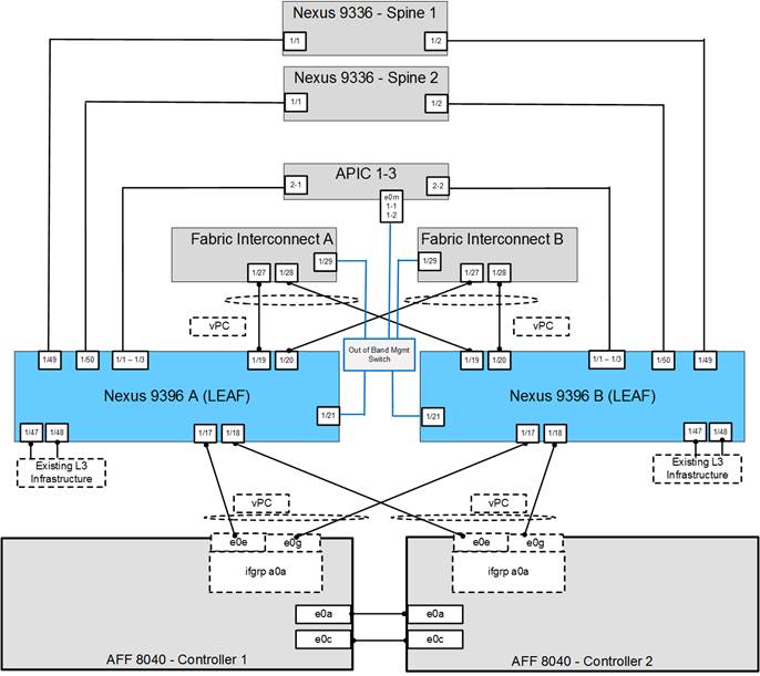
Table 5 through Table 14 provide the details of all the connections in use.
Table 5 Cisco Nexus 9396-A Cabling Information
| Local Device |
Local Port |
Connection |
Remote Device |
Remote Port |
| Cisco Nexus 9396 A
|
Eth1/1 |
10GbE |
APIC 1 |
Eth 2-1 |
| Eth1/2 |
10GbE |
APIC 2 |
Eth 2-1 |
|
| Eth1/3 |
10GbE |
APIC 3 |
Eth 2-1 |
|
| Eth1/17 |
10GbE |
NetApp controller 1 |
e0e |
|
| Eth1/18 |
10GbE |
NetApp controller 2 |
e0e |
|
| Eth1/19 |
10GbE |
Cisco UCS fabric interconnect A |
Eth1/31 |
|
| Eth1/20 |
10GbE |
Cisco UCS fabric interconnect B |
Eth1/31 |
|
| Eth1/21 |
GbE |
Common Services Mgmt. Switch |
Any |
|
| Eth1/49 |
40GbE |
Cisco 9336 Spine 1 |
Eth1/1 |
|
| Eth1/50 |
40GbE |
Cisco 9336 Spine 2 |
Eth1/1 |
|
|
|
MGMT0 |
GbE |
GbE management switch |
Any |
![]() Note: For devices requiring GbE connectivity, use the GbE Copper SFP+s (GLC-T=).
Note: For devices requiring GbE connectivity, use the GbE Copper SFP+s (GLC-T=).
Table 6 Cisco Nexus 9396-B Cabling Information
| Local Device |
Local Port |
Connection |
Remote Device |
Remote Port |
| Cisco Nexus 9396 A
|
Eth1/1 |
10GbE |
APIC 1 |
Eth 2-2 |
| Eth1/2 |
10GbE |
APIC 2 |
Eth 2-2 |
|
| Eth1/3 |
10GbE |
APIC 3 |
Eth 2-2 |
|
| Eth1/17 |
10GbE |
NetApp controller 1 |
e0g |
|
| Eth1/18 |
10GbE |
NetApp controller 2 |
e0g |
|
| Eth1/19 |
10GbE |
Cisco UCS fabric interconnect A |
Eth1/32 |
|
| Eth1/20 |
10GbE |
Cisco UCS fabric interconnect B |
Eth1/32 |
|
| Eth1/21 |
GbE |
Common Services Mgmt. Switch |
Any |
|
| Eth1/49 |
40GbE |
Cisco 9336 Spine 1 |
Eth1/2 |
|
| Eth1/50 |
40GbE |
Cisco 9336 Spine 2 |
Eth1/2 |
|
|
|
MGMT0 |
GbE |
GbE management switch |
Any |
Table 7 NetApp Controller-1 Cabling Information
| Local Device |
Local Port |
Connection |
Remote Device |
Remote Port |
| NetApp controller 1 |
e0M |
100MbE |
100MbE management switch |
Any |
| e0a |
GbE |
GbE management switch |
Any |
|
| e0P |
GbE |
SAS shelves |
ACP port |
|
| e0a |
10GbE |
NetApp Controller 2 |
e0a |
|
| e0c |
10GbE |
NetApp Controller 2 |
e0c |
|
| e0e |
10GbE |
Cisco Nexus 9000 A |
Eth 1/17 |
|
| e0g |
10GbE |
Cisco Nexus 9000 B |
Eth 1/17 |
![]() Note: When the term e0M is used, the physical Ethernet port to which the table is referring is the port indicated by a wrench icon on the rear of the chassis.
Note: When the term e0M is used, the physical Ethernet port to which the table is referring is the port indicated by a wrench icon on the rear of the chassis.
Table 8 NetApp controller 2 Cabling Information
| Local Device |
Local Port |
Connection |
Remote Device |
Remote Port |
| NetApp controller 2 |
e0M |
100MbE |
100MbE management switch |
Any |
| e0a |
GbE |
GbE management switch |
Any |
|
| e0P |
GbE |
SAS shelves |
ACP port |
|
| e0a |
10GbE |
NetApp Controller 1 |
e0a |
|
| e0c |
10GbE |
NetApp Controller 1 |
e0c |
|
| e0e |
10GbE |
Cisco Nexus 9000 A |
Eth 1/18 |
|
| e0g |
10GbE |
Cisco Nexus 9000 B |
Eth 1/18 |
Table 9 UCS Fabric Interconnect A Cabling Information
| Local Device |
Local Port |
Connection |
Remote Device |
Remote Port |
| Cisco UCS fabric interconnect A
|
Eth1/1 |
10GbE |
Cisco UCS Chassis FEX A |
IOM 1/1 |
| Eth1/2 |
10GbE |
Cisco UCS Chassis FEX A |
IOM 1/2 |
|
| Eth1/27 |
10GbE |
Cisco Nexus 9000 A |
Eth 1/19 |
|
| Eth1/28 |
10GbE |
Cisco Nexus 9000 B |
Eth 1/19 |
|
| Eth1/29 |
10GbE |
Management Switch |
Any |
|
| Eth1/31 |
10GbE |
Cisco Nexus 2232PP FEX A |
Uplink 1 |
|
| Eth1/32 |
10GbE |
Cisco Nexus 2232PP FEX A |
Uplink 2 |
|
| MGMT0 |
GbE |
GbE management switch |
Any |
|
| L1 |
GbE |
Cisco UCS fabric interconnect B |
L1 |
|
|
|
L2 |
GbE |
Cisco UCS fabric interconnect B |
L2 |
Table 10 UCS Fabric Interconnect B Cabling Information
| Local Device |
Local Port |
Connection |
Remote Device |
Remote Port |
| Cisco UCS fabric interconnect A
|
Eth1/1 |
10GbE |
Cisco UCS Chassis FEX B |
IOM 1/1 |
| Eth1/2 |
10GbE |
Cisco UCS Chassis FEX B |
IOM 1/2 |
|
| Eth1/27 |
10GbE |
Cisco Nexus 9000 A |
Eth 1/20 |
|
| Eth1/28 |
10GbE |
Cisco Nexus 9000 B |
Eth 1/20 |
|
| Eth1/29 |
10GbE |
Management Switch |
Any |
|
| Eth1/31 |
10GbE |
Cisco Nexus 2232PP FEX B |
Uplink 1 |
|
| Eth1/32 |
10GbE |
Cisco Nexus 2232PP FEX B |
Uplink 2 |
|
| MGMT0 |
GbE |
GbE management switch |
Any |
|
| L1 |
GbE |
Cisco UCS fabric interconnect B |
L1 |
|
|
|
L2 |
GbE |
Cisco UCS fabric interconnect B |
L2 |
Table 11 Cisco Nexus 2232 FEX A—Single Wire Management
| Local Device |
Local Port |
Connection |
Remote Device |
Remote Port |
| Cisco Nexus 2232PP FEX A
|
Port 1 |
10GbE |
Cisco UCS C-Series 1 |
Port 0 |
| Port 2 |
10GbE |
Cisco UCS C-Series 2 |
Port 0 |
Table 12 Cisco Nexus 2232 FEX B—Single Wire Management
| Local Device |
Local Port |
Connection |
Remote Device |
Remote Port |
| Cisco Nexus 2232PP FEX B
|
Port 1 |
10GbE |
Cisco UCS C-Series 1 |
Port 1 |
| Port 2 |
10GbE |
Cisco UCS C-Series 2 |
Port 1 |
Table 13 Cisco UCS C-Series 1
| Local Device |
Local Port |
Connection |
Remote Device |
Remote Port |
| Cisco UCS C-Series 1
|
Port 0 |
10GbE |
Cisco Nexus 2232PP FEX A |
Port 1 |
| Port 1 |
10GbE |
Cisco Nexus 2232PP FEX B |
Port 1 |
| Local Device |
Local Port |
Connection |
Remote Device |
Remote Port |
| Cisco UCS C-Series 2
|
Port 0 |
10GbE |
Cisco Nexus 2232PP FEX A |
Port 2 |
| Port 1 |
10GbE |
Cisco Nexus 2232PP FEX B |
Port 2 |
Controller AFF80XX Series
Refer to the Site Requirements Guide for planning the physical location of the storage systems. From the downloaded guide, refer to the following sections:
· Site Preparation
· System Connectivity Requirements
· Circuit Breaker, Power Outlet Balancing, System Cabinet Power Cord Plugs, and Console Pinout Requirements
· 80xx Series Systems
NetApp Hardware Universe
The NetApp Hardware Universe provides supported hardware and software components for the specific Data ONTAP version. It provides configuration information for all the NetApp storage appliances currently supported by the Data ONTAP software. It also provides a table of component compatibilities.
1. Confirm that the hardware and software components are supported with the version of Data ONTAP that you plan to install by using the NetApp Hardware Universe (HWU) application at the NetApp Support site.
2. Access the HWU application to view the System Configuration guides. Click the Controllers tab to view the compatibility between Data ONTAP software versions and NetApp storage appliances with the desired specifications.
3. Alternatively, to compare components by storage appliance, click Compare Storage Systems.
Controllers
Follow the physical installation procedures for the controllers which can be found in the AFF8000 Series product documentation at the NetApp Support site.
Disk Shelves
NetApp storage systems support a wide variety of disk shelves and disk drives. The complete list of disk shelves that are supported with AFF 80xx is available at the NetApp Support site.
When using SAS disk shelves with NetApp storage controllers, refer to the SAS Disk Shelves Universal SAS and ACP Cabling Guide for proper cabling guidelines.
Clustered Data ONTAP 8.3
Complete the Configuration Worksheet
Before running the setup script, complete the cluster setup worksheet from the Clustered Data ONTAP 8.3 Software Setup Guide.
|
|
How to Access the Configuration Worksheet Configuration Guide |
Comments |
| Configuration Worksheet |
Requires access to the NetApp Support site. |
Configure Clustered Data ONTAP Nodes
Before running the setup script, review the configuration worksheets in the Clustered Data ONTAP 8.3 Software Setup Guide to learn about the information required to configure clustered Data ONTAP. Table 15 lists the information that you will need to configure two clustered Data ONTAP nodes. You should customize the cluster detail values with the information that is applicable to your deployment.
Table 15 Clustered Data ONTAP Software Installation Prerequisites
| Cluster Detail |
Cluster Detail Value |
| Cluster Node01 IP address |
<<var_node01_mgmt_ip>> |
| Cluster Node01 netmask |
<<var_node01_mgmt_mask>> |
| Cluster Node01 gateway |
<<var_node01_mgmt_gateway>> |
| Cluster Node02 IP address |
<<var_node02_mgmt_ip>> |
| Cluster Node02 netmask |
<<var_node02_mgmt_mask>> |
| Cluster Node02 gateway |
<<var_node02_mgmt_gateway>> |
| Data ONTAP 8.3 URL |
<<var_url_boot_software>> |
Configure Node 01
To configure node 01, complete the following steps:
1. Connect to the storage system console port. You should see a Loader-A prompt. However, if the storage system is in a reboot loop, press Ctrl-C to exit the autoboot loop when you see this message:
Starting AUTOBOOT press Ctrl-C to abort
2. Allow the system to boot up.
autoboot
3. Press Ctrl-C when prompted.
![]() Note: If Data ONTAP 8.3 is not the version of software being booted, continue the following steps to install new software. If Data ONTAP 8.3 is the version being booted, select option 8 and y (Yes) to reboot the node, then continue with step 14.
Note: If Data ONTAP 8.3 is not the version of software being booted, continue the following steps to install new software. If Data ONTAP 8.3 is the version being booted, select option 8 and y (Yes) to reboot the node, then continue with step 14.
4. To install new software, select option 7.
7
5. Enter y (Yes) to perform an upgrade.
y
6. Select e0M for the network port you want to use for the download.
e0M
7. Enter y (Yes) to reboot now.
y
8. After reboot, enter the IP address, netmask, and default gateway for e0M in their respective places.
<<var_node01_mgmt_ip>> <<var_node01_mgmt_mask>> <<var_node01_mgmt_gateway>>
9. Enter the URL where the software can be found.
![]() Note: This web server must be pingable.
Note: This web server must be pingable.
<<var_url_boot_software>>
10. Press Enter for the user name, indicating no user name.
Enter
11. Enter y (Yes) to set the newly installed software as the default to be used for subsequent reboots.
y
12. Enter y (Yes) to reboot the node.
y
![]() Note: When installing new software, the system might perform firmware upgrades to the BIOS and adapter cards, causing reboots and possible stops at the Loader-A prompt. If these actions occur, the system might deviate from this procedure.
Note: When installing new software, the system might perform firmware upgrades to the BIOS and adapter cards, causing reboots and possible stops at the Loader-A prompt. If these actions occur, the system might deviate from this procedure.
13. Press Ctrl-C when you see this message:
Press Ctrl-C for Boot Menu
14. Select option 4 for Clean Configuration and Initialize All Disks.
4
15. Enter y (Yes) to zero disks, reset config, and install a new file system.
y
16. Enter y (Yes) to erase all the data on the disks.
Y
![]() Note: The initialization and creation of the root volume can take 90 minutes or more to complete, depending on the number of disks attached. After initialization is complete, the storage system reboots. You can continue with the node 02 configuration while the disks for node 01 are zeroing.
Note: The initialization and creation of the root volume can take 90 minutes or more to complete, depending on the number of disks attached. After initialization is complete, the storage system reboots. You can continue with the node 02 configuration while the disks for node 01 are zeroing.
Configure Node 02
To configure node 02, complete the following steps:
1. Connect to the storage system console port. You should see a Loader-A prompt. However, if the storage system is in a reboot loop, press Ctrl-C to exit the autoboot loop when you see this message:
Starting AUTOBOOT press Ctrl-C to abort…
2. Allow the system to boot up.
autoboot
3. Press Ctrl-C when prompted.
Ctrl-C
![]() If Data ONTAP 8.3 is not the version of software being booted, continue with the following steps to install new software. If Data ONTAP 8.3 is the version being booted, select option 8 and yes to reboot the node. Then continue with step 14.
If Data ONTAP 8.3 is not the version of software being booted, continue with the following steps to install new software. If Data ONTAP 8.3 is the version being booted, select option 8 and yes to reboot the node. Then continue with step 14.
4. To install new software, select option 7.
7
5. Enter y (Yes) to perform a non-disruptive upgrade.
y
6. Select e0M for the network port you want to use for the download.
e0M
7. Enter y (Yes) to reboot now.
y
8. Enter the IP address, netmask, and default gateway for e0M in their respective places.
<<var_node02_mgmt_ip>> <<var_node02_mgmt_mask>> <<var_node02_mgmt_gateway>>
9. Enter the URL where the software can be found.
![]() This web server must be pingable.
This web server must be pingable.
<<var_url_boot_software>>
10. Press Enter for the user name, indicating no user name.
Enter
11. Enter y (Yes) to set the newly installed software as the default to be used for subsequent reboots.
y
12. Enter y (Yes) to reboot the node.
y
![]() When installing new software, the system might perform firmware upgrades to the BIOS and adapter cards, causing reboots and possible stops at the Loader-A prompt. If these actions occur, the system might deviate from this procedure.
When installing new software, the system might perform firmware upgrades to the BIOS and adapter cards, causing reboots and possible stops at the Loader-A prompt. If these actions occur, the system might deviate from this procedure.
13. Press Ctrl-C when you see this message:
Press Ctrl-C for Boot Menu
14. Select option 4 for Clean Configuration and Initialize All Disks.
4
15. Enter y (Yes) to zero disks, reset config, and install a new file system.
y
16. Enter y (Yes) to erase all the data on the disks.
y
![]() The initialization and creation of the root volume can take 90 minutes or more to complete, depending on the number of disks attached. When initialization is complete, the storage system reboots.
The initialization and creation of the root volume can take 90 minutes or more to complete, depending on the number of disks attached. When initialization is complete, the storage system reboots.
Set Up Node
From a console port program attached to the storage controller A (node 01) console port, run the node setup script. This script appears when Data ONTAP 8.3 boots on the node for the first time. To set up the node, complete the following steps:
1. Follow the prompts to set up node 01.
Welcome to node setup.
You can enter the following commands at any time:
"help" or "?" - if you want to have a question clarified,
"back" - if you want to change previously answered questions, and
"exit" or "quit" - if you want to quit the setup wizard.
Any changes you made before quitting will be saved.
To accept a default or omit a question, do not enter a value.
This system will send event messages and weekly reports to NetApp Technical
Support.
To disable this feature, enter "autosupport modify -support disable" within 24
hours.
Enabling AutoSupport can significantly speed problem determination and
resolution should a problem occur on your system.
For further information on AutoSupport, see:
http://support.netapp.com/autosupport/
Type yes to confirm and continue {yes}: yes
Enter the node management interface port [e0M]: Enter
Enter the node management interface IP address: <<var_node01_mgmt_ip>>
Enter the node management interface netmask: <<var_node01_mgmt_mask>>
Enter the node management interface default gateway: <<var_node01_mgmt_gateway>>
A node management interface on port e0M with IP address <<var_node01_mgmt_ip>> has been created
This node has its management address assigned and is ready for cluster setup.
To complete cluster setup after all nodes are ready, download and run the System Setup utility from the NetApp Support Site and use it to discover the configured nodes.
For System Setup, this node's management address is: <<var_node01_mgmt_ip>>.
Alternatively, you can use the "cluster setup" command to configure the cluster.
2. Press Enter and log in to the node with the admin user id and no password.
3. At the node command prompt, enter the following commands:
::> storage failover modify -mode ha
Mode set to HA. Reboot node to activate HA.
::> system node reboot
Warning: Are you sure you want to reboot node "localhost"? {y|n}: y
4. After reboot, set up the node with the preassigned values.
Welcome to node setup.
You can enter the following commands at any time:
"help" or "?" - if you want to have a question clarified,
"back" - if you want to change previously answered questions, and
"exit" or "quit" - if you want to quit the setup wizard.
Any changes you made before quitting will be saved.
To accept a default or omit a question, do not enter a value.
Enter the node management interface port [e0M]: Enter
Enter the node management interface IP address [<<var_node01_mgmt_ip>>]: Enter
Enter the node management interface netmask [<<var_node01_mgmt_mask>>]: Enter
Enter the node management interface default gateway [<<var_node01_mgmt_gateway>>]: Enter
This node has its management address assigned and is ready for cluster setup.
To complete cluster setup after all nodes are ready, download and run the System Setup utility from the NetApp Support Site and use it to discover the configured nodes.
For System Setup, this node's management address is: <<var_node01_mgmt_ip>>.
Alternatively, you can use the "cluster setup" command to configure the cluster.
5. Log in to the node as the admin user and no password.
6. Repeat this procedure for storage cluster node 02.
Create Cluster on Node 01
In clustered Data ONTAP, the first node in the cluster performs the cluster create operation. All other nodes perform a cluster join operation. The first node in the cluster is considered node 01.
Table 16 Cluster create in Clustered Data ONTAP Prerequisites
| Cluster Detail |
Cluster Detail Value |
| Cluster name |
<<var_clustername>> |
| Clustered Data ONTAP base license |
<<var_cluster_base_license_key>> |
| Cluster management IP address |
<<var_clustermgmt_ip>> |
| Cluster management netmask |
<<var_clustermgmt_mask>> |
| Cluster management port |
<<var_clustermgmt_port>> |
| Cluster management gateway |
<<var_clustermgmt_gateway>> |
| Cluster node01 IP address |
<<var_node01_mgmt_ip>> |
| Cluster node01 netmask |
<<var_node01_mgmt_mask>> |
| Cluster node01 gateway |
<<var_node01_mgmt_gateway>> |
7. Run the cluster setup command to start the Cluster Setup wizard.
cluster setup
Welcome to the cluster setup wizard.
You can enter the following commands at any time:
"help" or "?" - if you want to have a question clarified,
"back" - if you want to change previously answered questions, and
"exit" or "quit" - if you want to quit the cluster setup wizard.
Any changes you made before quitting will be saved.
You can return to cluster setup at any time by typing "cluster setup".
To accept a default or omit a question, do not enter a value.
Do you want to create a new cluster or join an existing cluster? {create, join}:
![]() Note: If a login prompt appears instead of the Cluster Setup wizard, start the wizard by logging in by using the factory default settings and then enter the cluster setup command.
Note: If a login prompt appears instead of the Cluster Setup wizard, start the wizard by logging in by using the factory default settings and then enter the cluster setup command.
To create a new cluster, complete the following steps:
8. Run the following command to create a new cluster:
create
9. Enter no for the single-node cluster option.
Do you intend for this node to be used as a single node cluster? {yes, no} [no]: no
10. Enter no for cluster network using network switches.
Will the cluster network be configured to use network switches? [yes]:no
11. The system defaults are displayed. Enter yes to use the system defaults. Use the following prompts to configure the cluster ports.
Existing cluster interface configuration found:
Port MTU IP Netmask
e0a 9000 169.254.118.102 255.255.0.0
e0b 9000 169.254.152.110 255.255.0.0
e0c 9000 169.254.191.92 255.255.0.0
e0d 9000 169.254.233.52 255.255.0.0
Do you want to use this configuration? {yes, no} [yes]: no
System Defaults:
Private cluster network ports [e0a,e0c].
Cluster port MTU values will be set to 9000.
Cluster interface IP addresses will be automatically generated.
Do you want to use these defaults? {yes, no} [yes]: yes
12. The steps to create a cluster are displayed.
Enter the cluster administrators (username “admin) password: <<var_password>>
Retype the password: <<var_password>>
It can take several minutes to create cluster interfaces...
Step 1 of 5: Create a Cluster
You can type "back", "exit", or "help" at any question.
Enter the cluster name: <<var_clustername>>
Enter the cluster base license key: <<var_cluster_base_license_key>>
Creating cluster <<var_clustername>>
Enter an additional license key []:<<var_iscsi_license>>
![]() Note: The cluster is created. This can take a minute or two.
Note: The cluster is created. This can take a minute or two.
![]() Note: For this validated architecture, NetApp recommends installing license keys for NetApp SnapRestore®, NetApp FlexClone®, and NetApp SnapManager® Suite. In addition, install all required storage protocol licenses and all licenses that came with the AFF bundle. After you finish entering the license keys, press Enter.
Note: For this validated architecture, NetApp recommends installing license keys for NetApp SnapRestore®, NetApp FlexClone®, and NetApp SnapManager® Suite. In addition, install all required storage protocol licenses and all licenses that came with the AFF bundle. After you finish entering the license keys, press Enter.
Enter the cluster management interface port [e0e]: e0i
Enter the cluster management interface IP address: <<var_clustermgmt_ip>>
Enter the cluster management interface netmask: <<var_clustermgmt_mask>>
Enter the cluster management interface default gateway: <<var_clustermgmt_gateway>>
13. Enter the DNS domain name.
Enter the DNS domain names:<<var_dns_domain_name>>
Enter the name server IP addresses:<<var_nameserver_ip>>
![]() If you have more than one name server IP address, separate the IP addresses with a comma.
If you have more than one name server IP address, separate the IP addresses with a comma.
14. Set up the node.
Where is the controller located []:<<var_node_location>>
Enter the node management interface port [e0M]: e0M
Enter the node management interface IP address [<<var_node01_mgmt_ip>>]: Enter
Enter the node management interface netmask [<<var_node01_mgmt_mask>>]: Enter
Enter the node management interface default gateway [<<var_node01_mgmt_gateway>>]: Enter
The node management interface has been modified to use port e0M with IP address <<var_node01_mgmt_ip>>.
This system will send event messages and weekly reports to NetApp Technical Support.
To disable this feature, enter "autosupport modify -support disable" within 24 hours.
Enabling AutoSupport can significantly speed problem determination and resolution should a problem occur on your system.
For further information on AutoSupport, please see: http://support.netapp.com/autosupport/
Press enter to continue: Enter
Cluster "<<var_clustername>>" has been created.
To complete cluster setup, you must join each additional node to the cluster
by running "cluster setup" on each node.
Once all nodes have been joined to the cluster, see the Clustered Data ONTAP
Software Setup Guide for information about additional system configuration
tasks. You can find the Software Setup Guide on the NetApp Support Site.
To complete system configuration, you can use either OnCommand System Manager
or the Data ONTAP command-line interface.
To access OnCommand System Manager, point your web browser to the cluster
management IP address (<<var_clustermgmt_ip>>).
To access the command-line interface, connect to the cluster management
IP address (for example, ssh admin@<<var_clustermgmt_ip>>).
<<var_clustername>>::>
![]() Note: The node management interface can be on the same subnet as the cluster management interface, or it can be on a different subnet. In this document it is assumed to be on the same subnet.
Note: The node management interface can be on the same subnet as the cluster management interface, or it can be on a different subnet. In this document it is assumed to be on the same subnet.
Join Node 02 to Cluster
The first node in the cluster performs the cluster create operation. All other nodes perform a cluster join operation. The first node in the cluster is considered node 01, and the node joining the cluster in this example is node 02.
Table 17 Cluster join in Clustered Data ONTAP Prerequisites
| Cluster Detail |
Cluster Detail Value |
| Cluster name |
<<var_clustername>> |
| Cluster management IP address |
<<var_clustermgmt_ip>> |
| Cluster node02 IP address |
<<var_node02_mgmt_ip>> |
| Cluster node02 netmask |
<<var_node02_mgmt_mask>> |
| Cluster node02 gateway |
<<var_node02_mgmt_gateway>> |
To join node 02 to the existing cluster, complete the following steps:
1. If prompted, enter admin in the login prompt.
admin
2. Run the cluster setup command to start the Cluster Setup wizard.
cluster setup
This node's storage failover partner is already a member of a cluster.
Storage failover partners must be members of the same cluster.
The cluster setup wizard will default to the cluster join dialog.
Welcome to the cluster setup wizard.
You can enter the following commands at any time:
"help" or "?" - if you want to have a question clarified,
"back" - if you want to change previously answered questions, and
"exit" or "quit" - if you want to quit the cluster setup wizard.
Any changes you made before quitting will be saved.
You can return to cluster setup at any time by typing "cluster setup".
To accept a default or omit a question, do not enter a value.
Do you want to create a new cluster or join an existing cluster?
{join}:
![]() Note: If a login prompt is displayed instead of the Cluster Setup wizard, start the wizard by logging in using the factory default settings, and then enter the cluster setup command.
Note: If a login prompt is displayed instead of the Cluster Setup wizard, start the wizard by logging in using the factory default settings, and then enter the cluster setup command.
3. Run the following command to join a cluster:
join
4. Data ONTAP detects the existing cluster and agrees to join the same cluster. Follow the prompts to join the cluster.
Existing cluster interface configuration found:
Port MTU IP Netmask
e0a 9000 169.254.1.79 255.255.0.0
e0b 9000 169.254.54.223 255.255.0.0
e0c 9000 169.254.100.157 255.255.0.0
e0d 9000 169.254.138.142 255.255.0.0
Do you want to use this configuration? {yes, no} [yes]: no
System Defaults:
Private cluster network ports [e0a,e0c].
Cluster port MTU values will be set to 9000.
Cluster interface IP addresses will be automatically generated.
Do you want to use these defaults? {yes, no} [yes]:Enter
It can take several minutes to create cluster interfaces...
5. The steps to join a cluster are displayed.
Step 1 of 3: Join an Existing Cluster
You can type "back", "exit", or "help" at any question.
Enter the name of the cluster you would like to join [<<var_clustername>>]:Enter
Joining cluster <<var_clustername>>
Starting cluster support services ..
This node has joined the cluster <<var_clustername>>.
Step 2 of 3: Configure Storage Failover (SFO)
You can type "back", "exit", or "help" at any question.
SFO is enabled.
Step 3 of 3: Set Up the Node
You can type "back", "exit", or "help" at any question.
Notice: HA is configured in management.
![]() Note: The node should find the cluster name. The cluster joining can take a few minutes.
Note: The node should find the cluster name. The cluster joining can take a few minutes.
6. Set up the node.
Enter the node management interface port [e0M]: e0M
Enter the node management interface IP address [<<var_node02_mgmt_ip>>]: Enter
Enter the node management interface netmask [<<var_node02_netmask>>]: Enter
Enter the node management interface default gateway [<<var_node02_gw>>]: Enter
The node management interface has been modified to use port e0M with IP address <<var_node02_mgmt_ip>>.
This system will send event messages and weekly reports to NetApp Technical Support.
To disable this feature, enter "autosupport modify -support disable" within 24 hours.
Enabling AutoSupport can significantly speed problem determination and resolution should a problem occur on your system.
For further information on AutoSupport, please see: http://support.netapp.com/autosupport/
Press enter to continue: Enter
This node has been joined to cluster "<<var_clustername>>".
To complete cluster setup, you must join each additional node to the cluster
by running "cluster setup" on each node.
Once all nodes have been joined to the cluster, see the Clustered Data ONTAP
Software Setup Guide for information about additional system configuration
tasks. You can find the Software Setup Guide on the NetApp Support Site.
To complete system configuration, you can use either OnCommand System Manager
or the Data ONTAP command-line interface.
To access OnCommand System Manager, point your web browser to the cluster
management IP address (<<var_clustermgmt_ip>>).
To access the command-line interface, connect to the cluster management
IP address (for example, ssh admin@<<var_clustermgmt_ip>>).
![]() Note: The node management interface can be on the same subnet as the cluster management interface, or it can be on a different subnet. In this document it is assumed to be on the same subnet.
Note: The node management interface can be on the same subnet as the cluster management interface, or it can be on a different subnet. In this document it is assumed to be on the same subnet.
Log In to Cluster
To log in to the cluster, complete the following steps:
1. Open an SSH connection to either the cluster IP or host name.
2. Log in to the admin user with the password you provided earlier.
Zero All Spare Disks
To zero all spare disks in the cluster, complete the following step:
1. Run the following command:
disk zerospares
![]() Note: Disk autoassign should have assigned half of the connected disks to each node in the HA pair. If a different disk assignment is required, disk autoassignment must be disabled on both nodes in the HA pair by running the disk option modify command. Spare disks can then be moved from one node to another by running the disk removeowner and disk assign commands.
Note: Disk autoassign should have assigned half of the connected disks to each node in the HA pair. If a different disk assignment is required, disk autoassignment must be disabled on both nodes in the HA pair by running the disk option modify command. Spare disks can then be moved from one node to another by running the disk removeowner and disk assign commands.
Set Onboard UTA2 Ports Personality
To set the personality of the onboard Unified Target Adapter 2 (UTA2), complete the following steps:
1. Verify the Current Mode and Current Type of the ports by running the ucadmin show command.
ucadmin show
Current Current Pending Pending Admin
Node Adapter Mode Type Mode Type Status
------------ ------- ------- --------- ------- --------- -----------
<<var_node01>>
0e cna target - - online
<<var_node01>>
0f cna target - - online
<<var_node01>>
0g cna target - - online
<<var_node01>>
0h cna target - - online
<<var_node02>>
0e cna target - - online
<<var_node02>>
0f cna target - - online
<<var_node02>>
0g cna target - - online
<<var_node02>>
0h cna target - - online
8 entries were displayed.
2. Verify that the Current Mode of all the ports in use is cna and the Current Type is set to target. If not, change the port personality by running the following command:
ucadmin modify -node <home node of the port> -adapter <port name> -mode cna -type target
![]() Note: The ports must be offline to run this command. To take an adapter offline, run the fcp adapter modify –node <home node of the port> -adapter <port name> -state down command. Ports must be converted in pairs, for example, 0c and 0d, after which, a reboot is required, and the ports must be brought back to the up state.
Note: The ports must be offline to run this command. To take an adapter offline, run the fcp adapter modify –node <home node of the port> -adapter <port name> -state down command. Ports must be converted in pairs, for example, 0c and 0d, after which, a reboot is required, and the ports must be brought back to the up state.
Set Auto-Revert on Cluster Management
To set the auto-revert parameter on the cluster management interface, complete the following step:
![]() Note: The storage virtual machine (SVM) is referred to as Vserver (or vserver) in the GUI and CLI.
Note: The storage virtual machine (SVM) is referred to as Vserver (or vserver) in the GUI and CLI.
1. Run the following command:
network interface modify –vserver <<var_clustername>> -lif cluster_mgmt –auto-revert true
Set Up Management Broadcast Domain
To set up the default broadcast domain for management network interfaces, complete the following step:
1. Run the following commands:
broadcast-domain remove-ports –broadcast-domain Default –ports <<var_node01>>:e0b,<<var_node01>>:e0d,<<var_node01>>:e0e,<<var_node01>>:e0f,<<var_node01>>:e0g,<<var_node01>>:e0h,<<var_node01>>:e0j,<<var_node01>>:e0k,<<var_node01>>:e0l,<<var_node02>>:e0b,<<var_node02>>:e0d,<<var_node02>>:e0e,<<var_node02>>:e0f,<<var_node02>>:e0g,<<var_node02>>:e0h,<<var_node02>>:e0j,<<var_node02>>:e0k,<<var_node02>>:e0l
broadcast-domain show
Set Up Service Processor Network Interface
To assign a static IPv4 address to the service processor on each node, complete the following step:
1. Run the following commands:
system service-processor network modify –node <<var_node01>> -address-family IPv4 –enable true –dhcp none –ip-address <<var_node01_sp_ip>> -netmask <<var_node01_sp_mask>> -gateway <<var_node01_sp_gateway>>
system service-processor network modify –node <<var_node02>> -address-family IPv4 –enable true –dhcp none –ip-address <<var_node02_sp_ip>> -netmask <<var_node02_sp_mask>> -gateway <<var_node02_sp_gateway>>
![]() Note: The service processor IP addresses should be in the same subnet as the node management IP addresses.
Note: The service processor IP addresses should be in the same subnet as the node management IP addresses.
Create Aggregates
An aggregate containing the root volume is created during the Data ONTAP setup process. To create additional aggregates, determine the aggregate name, the node on which to create it, and the number of disks it will contain.
To create new aggregates, complete the following steps:
1. Run the following commands:
aggr create -aggregate aggr1_node01 -nodes <<var_node01>> -diskcount <<var_num_disks>>
aggr create -aggregate aggr1_node02 -nodes <<var_node02>> -diskcount <<var_num_disks>>
![]() Note: Retain at least one disk (select the largest disk) in the configuration as a spare. A best practice is to have at least one spare for each disk type and size.
Note: Retain at least one disk (select the largest disk) in the configuration as a spare. A best practice is to have at least one spare for each disk type and size.
![]() Note: Start with five disks initially; you can add disks to an aggregate when additional storage is required. In an AFF configuration with a small number of SSDS, it may be desirable to create an aggregate with all but one remaining disk (spare) assigned to the controller.
Note: Start with five disks initially; you can add disks to an aggregate when additional storage is required. In an AFF configuration with a small number of SSDS, it may be desirable to create an aggregate with all but one remaining disk (spare) assigned to the controller.
![]() Note: The aggregate cannot be created until disk zeroing completes. Run the aggr show command to display aggregate creation status. Do not proceed until both aggr1_node1 and aggr1_node2 are online.
Note: The aggregate cannot be created until disk zeroing completes. Run the aggr show command to display aggregate creation status. Do not proceed until both aggr1_node1 and aggr1_node2 are online.
2. Disable NetApp Snapshot® copies for the two data aggregates recently created.
node run <<var_node01>> aggr options aggr1_node01 nosnap on
node run <<var_node02>> aggr options aggr1_node02 nosnap on
3. Delete any existing Snapshot copies for the two data aggregates.
node run <<var_node01>> snap delete –A –a –f aggr1_node01
node run <<var_node02>> snap delete –A –a –f aggr1_node02
4. Rename the root aggregate on node 01 to match the naming convention for this aggregate on node 02.
aggr show
aggr rename –aggregate aggr0 –newname <<var_node01_rootaggrname>>
Verify Storage Failover
To confirm that storage failover is enabled, run the following commands for a failover pair:
1. Verify the status of storage failover.
storage failover show
![]() Note: Both the nodes <<var_node01>> and <<var_node02>> must be capable of performing a takeover. Continue with step 3 if the nodes are capable of performing a takeover.
Note: Both the nodes <<var_node01>> and <<var_node02>> must be capable of performing a takeover. Continue with step 3 if the nodes are capable of performing a takeover.
2. Enable failover on one of the two nodes.
storage failover modify -node <<var_node01>> -enabled true
![]() Note: Enabling failover on one node enables it for both nodes.
Note: Enabling failover on one node enables it for both nodes.
3. Verify the HA status for a two-node cluster.
![]() Note: This step is not applicable for clusters with more than two nodes.
Note: This step is not applicable for clusters with more than two nodes.
cluster ha show
4. Continue with step 6 if high availability is configured.
5. Enable HA mode only for the two-node cluster.
![]() Note: Do not run this command for clusters with more than two nodes because it will cause problems with failover.
Note: Do not run this command for clusters with more than two nodes because it will cause problems with failover.
cluster ha modify -configured true
Do you want to continue? {y|n}: y
6. Verify that hardware assist is correctly configured and, if needed, modify the partner IP address.
storage failover hwassist show
storage failover modify –hwassist-partner-ip <<var_node02_mgmt_ip>> -node <<var_node01>>
storage failover modify –hwassist-partner-ip <<var_node01_mgmt_ip>> -node <<var_node02>>
Disable Flow Control on UTA2 Ports
NetApp recommends disabling flow control on all of the 10GbE and UTA2 ports that are connected to external devices. To disable flow control, complete the following steps:
1. Run the following commands to configure node 01:
network port modify -node <<var_node01>> -port e0a,e0b,e0c,e0d,e0e,e0f,e0g,e0h -flowcontrol-admin none
Warning: Changing the network port settings will cause a several second interruption in carrier.
Do you want to continue? {y|n}: y
2. Run the following commands to configure node 02:
network port modify -node <<var_node02>> -port e0a,e0b,e0c,e0d,e0e,e0f,e0g,e0hq -flowcontrol-admin none
Warning: Changing the network port settings will cause a several second interruption in carrier.
Do you want to continue? {y|n}: y
network port show –fields flowcontrol-admin
Disable Unused FcoE Ports
Unused data FCoE ports on active interfaces should be disabled. To disable these ports, complete the following step:
1. Run the following commands:
fcp adapter modify -node <<var_node01>> -adapter 0e –state down
fcp adapter modify -node <<var_node01>> -adapter 0g –state down
fcp adapter modify -node <<var_node02>> -adapter 0e –state down
fcp adapter modify -node <<var_node02>> -adapter 0g –state down
fcp adapter show –fields state
Configure NTP
To configure time synchronization on the cluster, complete the following steps:
1. To set the time zone for the cluster, run the following command:
timezone <<var_timezone>>
![]() Note: For example, in the eastern United States, the time zone is America/New_York.
Note: For example, in the eastern United States, the time zone is America/New_York.
2. To set the date for the cluster, run the following command:
date <ccyymmddhhmm.ss>
![]() Note: The format for the date is <[Century][Year][Month][Day][Hour][Minute].[Second]>; for example, 201309081735.17
Note: The format for the date is <[Century][Year][Month][Day][Hour][Minute].[Second]>; for example, 201309081735.17
3. Configure the Network Time Protocol (NTP) servers for the cluster.
cluster time-service ntp server create -server <<var_global_ntp_server_ip>>
Configure SNMP
To configure SNMP, complete the following steps:
1. Configure SNMP basic information, such as the location and contact. When polled, this information is visible as the sysLocation and sysContact variables in SNMP.
snmp contact <<var_snmp_contact>>
snmp location “<<var_snmp_location>>
snmp init 1
options snmp.enable on
2. Configure SNMP traps to send to remote hosts, such as a DFM server or another fault management system.
snmp traphost add <<var_oncommand_server_fqdn>>
Configure SNMPv1 Access
To configure SNMPv1 access, complete the following step:
1. Set the shared secret plain-text password, which is called a community.
snmp community add ro <<var_snmp_community>>
2. Use the delete all command with caution. If community strings are used for other monitoring products, the delete all command will remove them.
Create SNMPv3 User
SNMPv3 requires that a user be defined and configured for authentication. To create and configure a user for SNMPv3, complete the following steps:
1. Create a user called snmpv3user.
security login create -username snmpv3user -authmethod usm -application snmp
2. Enter the authoritative entity's engine ID and select md5 as the authentication protocol.
3. Run the security snmpusers command to view the engine ID.
4. When prompted, enter an eight-character minimum-length password for the authentication protocol.
5. Select des as the privacy protocol.
6. When prompted, enter an eight-character minimum-length password for the privacy protocol.
Configure AutoSupport
AutoSupport sends support summary information to NetApp through HTTPS. To configure AutoSupport, complete the following step:
1. Run the following command:
system node autosupport modify -node * -state enable –mail-hosts <<var_mailhost>> -transport https -support enable -noteto <<var_storage_admin_email>>
Enable Cisco Discovery Protocol
To enable Cisco Discovery Protocol (CDP) on the NetApp storage controllers, complete the following step:
![]() Note: To be effective, CDP must also be enabled on directly connected networking equipment such as switches and routers.
Note: To be effective, CDP must also be enabled on directly connected networking equipment such as switches and routers.
2. Run the following command to enable CDP on Data ONTAP:
node run -node * options cdpd.enable on
Create Jumbo Frame MTU Broadcast Domains in Clustered Data ONTAP
To create a data broadcast domain with an MTU of 9000, complete the following step:
1. Run the following commands to create a broadcast domain on Data ONTAP:
broadcast-domain create -broadcast-domain Infra_NFS -mtu 9000
broadcast-domain create -broadcast-domain Infra_iSCSI-A -mtu 9000
broadcast-domain create -broadcast-domain Infra_iSCSI-B -mtu 9000
Create Interface Groups
To create the LACP interface groups for the 10GbE data interfaces, complete the following step:
1. Run the following commands to create the LACP interface groups:
ifgrp create -node <<var_node01>> -ifgrp a0a -distr-func port -mode multimode_lacp
ifgrp add-port -node <<var_node01>> -ifgrp a0a -port e0e
ifgrp add-port -node <<var_node01>> -ifgrp a0a -port e0g
ifgrp create -node <<var_node02>> -ifgrp a0a -distr-func port -mode multimode_lacp
ifgrp add-port -node <<var_node02>> -ifgrp a0a -port e0e
ifgrp add-port -node <<var_node02>> -ifgrp a0a -port e0g
ifgrp show
Create VLANs
To create VLANs, complete the following steps:
1. Create NFS VLAN ports and add them to the data broadcast domain.
network port modify –node <<var_node01>> -port a0a –mtu 9000
network port modify –node <<var_node02
>> -port a0a –mtu 9000
network port vlan create –node <<var_node01>> -vlan-name a0a-<<var_nfs_vlan_id>>
network port vlan create –node <<var_node02>> -vlan-name a0a-<<var_nfs_vlan_id>>
broadcast-domain add-ports -broadcast-domain Infra_NFS -ports <<var_node01>>:a0a-<<var_nfs_vlan_id>>, <<var_node02>>:a0a-<<var_nfs_vlan_id>>
2. Create iSCSI VLAN ports and add them to the data broadcast domain.
network port vlan create –node <<var_node01>> -vlan-name a0a-<<var_iscsi_vlan_A_id>>
network port vlan create –node <<var_node01>> -vlan-name a0a-<<var_iscsi_vlan_B_id>>
network port vlan create –node <<var_node02>> -vlan-name a0a-<<var_iscsi_vlan_A_id>>
network port vlan create –node <<var_node02>> -vlan-name a0a-<<var_iscsi_vlan_B_id>>
broadcast-domain add-ports -broadcast-domain Infra_iSCSI-A -ports <<var_node01>>:a0a-<<var_iscsi_vlan_A_id>>,<<var_node02>>:a0a-<<var_iscsi_vlan_A_id>>
broadcast-domain add-ports -broadcast-domain Infra_iSCSI-B -ports <<var_node01>>:a0a-<<var_iscsi_vlan_B_id>>,<<var_node02>>:a0a-<<var_iscsi_vlan_B_id>>
Create Storage Virtual Machine
To create an infrastructure storage virtual machine (SVM, formerly known as Vserver), complete the following steps:
![]() Note: The storage virtual machine (SVM) is referred to as a Vserver (or vserver) in the GUI and CLI.
Note: The storage virtual machine (SVM) is referred to as a Vserver (or vserver) in the GUI and CLI.
1. Run the vserver create command.
vserver create –vserver Infra-SVM –rootvolume rootvol –aggregate aggr1_node01 –rootvolume-security-style unix
2. Select the SVM data protocols to configure, keeping nfs and iscsi.
vserver remove-protocols –vserver Infra-SVM -protocols fcp,cifs,ndmp
3. Add the two data aggregates to the Infra-SVM aggregate list for NetApp Virtual Storage Console (VSC).
vserver modify –vserver Infra-SVM –aggr-list aggr1_node01,aggr1_node02
4. Enable and run the NFS protocol in the Infra-SVM.
nfs create -vserver Infra-SVM -udp disabled
5. Turn on the SVM vstorage parameter for the NetApp NFS VAAI plugin.
vserver nfs modify –vserver Infra-SVM –vstorage enabled
vserver nfs show
Create Load-Sharing Mirrors of SVM Root Volume
To create a load-sharing mirror of an SVM root volume, complete the following steps:
1. Create a volume to be the load-sharing mirror of the infrastructure SVM root volume on each node.
volume create –vserver Infra-SVM –volume rootvol_m01 –aggregate aggr1_node01 –size 1GB –type DP
volume create –vserver Infra-SVM –volume rootvol_m02 –aggregate aggr1_node02 –size 1GB –type DP
2. Create a job schedule to update the root volume mirror relationships every 15 minutes.
job schedule interval create -name 15min -minutes 15
3. Create the mirroring relationships.
snapmirror create –source-path //Infra-SVM/rootvol –destination-path //Infra-SVM/rootvol_m01 –type LS -schedule 15min
snapmirror create –source-path //Infra-SVM/rootvol –destination-path //Infra-SVM/rootvol_m02 –type LS -schedule 15min
4. Initialize the mirroring relationship.
snapmirror initialize-ls-set –source-path //Infra-SVM/rootvol
snapmirror show
Create iSCSI Service
To create the iSCSI service, complete the following step:
1. Create the iSCSI service on each SVM. This command also starts the iSCSI service and sets the iSCSI IQN for the SVM.
iscsi create -vserver Infra-SVM
iscsi show
Configure HTTPS Access
To configure secure access to the storage controller, complete the following steps:
1. Increase the privilege level to access the certificate commands.
set -privilege diag
Do you want to continue? {y|n}: y
2. Generally, a self-signed certificate is already in place. Verify the certificate by running the following command:
security certificate show
3. For each SVM shown, the certificate common name should match the DNS FQDN of the SVM. The four default certificates should be deleted and replaced by either self-signed certificates or certificates from a Certificate Authority (CA) To delete the default certificates, run the following commands:
![]() Note: Deleting expired certificates before creating new certificates is a best practice. Run the security certificate delete command to delete expired certificates. In the following command, use TAB completion to select and delete each default certificate.
Note: Deleting expired certificates before creating new certificates is a best practice. Run the security certificate delete command to delete expired certificates. In the following command, use TAB completion to select and delete each default certificate.
security certificate delete [TAB] …
Example: security certificate delete -vserver Infra-SVM -common-name Infra-SVM -ca Infra-SVM -type server -serial 552429A6
4. To generate and install self-signed certificates, run the following commands as one-time commands. Generate a server certificate for Infra-SVM and the cluster SVM. Use TAB completion to aid in the completion of these commands.
security certificate create [TAB] …
Example: security certificate create -common-name infra-svm.ciscorobo.com -type server -size 2048 -country US -state "California" -locality "San Jose" -organization "Cisco" -unit "UCS" -email-addr "abc@cisco.com" -expire-days 365 -protocol SSL -hash-function SHA256 -vserver Infra-SVM
5. To obtain the values for the parameters that would be required in step 6, run the security certificate show command.
6. Enable each certificate that was just created by using the –server-enabled true and –client-enabled false parameters. Use TAB completion to aid in the completion of these commands.
security ssl modify [TAB] …
Example: security ssl modify -vserver clus -server-enabled true -client-enabled false -ca clus.ciscorobo.com -serial 55243646 -common-name clus.ciscorobo.com
7. Configure and enable SSL and HTTPS access and disable HTTP access.
system services web modify -external true -sslv3-enabled true
Warning: Modifying the cluster configuration will cause pending web service requests to be interrupted as the web servers are restarted.
Do you want to continue {y|n}: y
system services firewall policy delete -policy mgmt -service http –vserver <<var_clustername>>
8. It is normal for some of these commands to return an error message stating that the entry does not exist.
9. Change back to the normal admin privilege level and set up the system to allow SVM logs to be available by web.
set –privilege admin
vserver services web modify –name spi|ontapi|compat –vserver * -enabled true
Configure NFSv3
To configure NFSv3 on the SVM, complete the following steps:
1. Create a new rule for each ESXi host in the default export policy. Assign a rule for each ESXi host created so that each host has its own rule index. For example, the first ESXi host has rule index 1, the second ESXi host has rule index 2, and so on.
vserver export-policy rule create –vserver Infra-SVM -policyname default –ruleindex 1 –protocol nfs -clientmatch <<var_esxi_host1_nfs_ip>> -rorule sys –rwrule sys -superuser sys –allow-suid false
vserver export-policy rule create –vserver Infra-SVM -policyname default –ruleindex 2 –protocol nfs -clientmatch <<var_esxi_host2_nfs_ip>> -rorule sys –rwrule sys -superuser sys –allow-suid false
vserver export-policy rule show
2. Assign the FlexPod export policy to the infrastructure SVM root volume.
volume modify –vserver Infra-SVM –volume rootvol –policy default
Create FlexVol Volumes
The following information is required to create a FlexVol volume:
· Volume name
· Volume size
· Aggregate on which the volume exists
To create a NetApp FlexVol® volume, complete the following step:
1. Run the following commands:
volume create -vserver Infra-SVM -volume infra_datastore_1 -aggregate aggr1_node02 -size 500GB -state online -policy default -junction-path /infra_datastore_1 -space-guarantee none -percent-snapshot-space 0
volume create -vserver Infra-SVM -volume infra_swap -aggregate aggr1_node01 -size 100GB -state online -policy default -junction-path /infra_swap -space-guarantee none -percent-snapshot-space 0 -snapshot-policy none
volume create -vserver Infra-SVM -volume esxi_boot -aggregate aggr1_node01 -size 100GB -state online -policy default -space-guarantee none -percent-snapshot-space 0
snapmirror update-ls-set -source-path //Infra-SVM/rootvol
Create Boot LUNs
To create two boot LUNs, complete the following step:
1. Run the following commands:
lun create -vserver Infra-SVM -volume esxi_boot -lun VM-Host-Infra-01 -size 15GB -ostype vmware -space-reserve disabled
lun create -vserver Infra-SVM -volume esxi_boot -lun VM-Host-Infra-02 -size 15GB -ostype vmware -space-reserve disabled
Enable Deduplication
To enable deduplication on appropriate volumes, complete the following step:
1. Run the following commands:
volume efficiency on –vserver Infra-SVM -volume infra_datastore_1
volume efficiency on –vserver Infra-SVM -volume esxi_boot
Create iSCSI LIFs
To create four iSCSI LIFs (two on each node), complete the following step:
1. Run the following commands:
network interface create -vserver Infra-SVM -lif iscsi_lif01a -role data -data-protocol iscsi -home-node <<var_node01>> -home-port a0a-<<var_iscsi_vlan_A_id>> -address <<var_node01_iscsi_lif01a_ip>> -netmask <<var_node01_iscsi_lif01a_mask>> –status-admin up –failover-policy disabled –firewall-policy data –auto-revert false
network interface create -vserver Infra-SVM -lif iscsi_lif01b -role data -data-protocol iscsi -home-node <<var_node01>> -home-port a0a-<<var_iscsi_vlan_B_id>> -address <<var_node01_iscsi_lif01b_ip>> -netmask <<var_node01_iscsi_lif01b_mask>> –status-admin up –failover-policy disabled –firewall-policy data –auto-revert false
network interface create -vserver Infra-SVM -lif iscsi_lif02a -role data -data-protocol iscsi -home-node <<var_node02>> -home-port a0a-<<var_iscsi_vlan_A_id>> -address <<var_node02_iscsi_lif01a_ip>> -netmask <<var_node02_iscsi_lif01a_mask>> –status-admin up –failover-policy disabled –firewall-policy data –auto-revert false
network interface create -vserver Infra-SVM -lif iscsi_lif02b -role data -data-protocol iscsi -home-node <<var_node02>> -home-port a0a-<<var_iscsi_vlan_B_id>> -address <<var_node02_iscsi_lif01b_ip>> -netmask <<var_node02_iscsi_lif01b_mask>> –status-admin up –failover-policy disabled –firewall-policy data –auto-revert false
network interface show
Create NFS LIF
To create an NFS LIF, complete the following step:
1. Run the following commands:
network interface create -vserver Infra-SVM -lif nfs_infra_swap -role data -data-protocol nfs -home-node <<var_node01>> -home-port a0a-<<var_nfs_vlan_id>> –address <<var_node01_nfs_lif_infra_swap_ip>> -netmask <<var_node01_nfs_lif_infra_swap_mask>> -status-admin up –failover-policy broadcast-domain-wide –firewall-policy data –auto-revert true
network interface create -vserver Infra-SVM -lif nfs_infra_datastore_1 -role data -data-protocol nfs -home-node <<var_node02>> -home-port a0a-<<var_nfs_vlan_id>> –address <<var_node02_nfs_lif_infra_datastore_1_ip>> -netmask <<var_node02_nfs_lif_infra_datastore_1_mask>> -status-admin up –failover-policy broadcast-domain-wide –firewall-policy data –auto-revert true
network interface show
![]() Note: NetApp recommends creating a new LIF for each datastore.
Note: NetApp recommends creating a new LIF for each datastore.
Add Infrastructure SVM Administrator
To add the infrastructure SVM administrator and SVM administration LIF in the out-of-band management network, complete the following steps:
1. Run the following commands:
network interface create –vserver Infra-SVM –lif vsmgmt –role data –data-protocol none –home-node <<var_node02>> -home-port e0i –address <<var_svm_mgmt_ip>> -netmask <<var_svm_mgmt_mask>> -status-admin up –failover-policy broadcast-domain-wide –firewall-policy mgmt –auto-revert true
![]() Note: The SVM management IP in this step should be in the same subnet as the storage cluster management IP.
Note: The SVM management IP in this step should be in the same subnet as the storage cluster management IP.
2. Create a default route to allow the SVM management interface to reach the outside world.
network route create –vserver Infra-SVM -destination 0.0.0.0/0 –gateway <<var_svm_mgmt_gateway>>
network route show
3. Set a password for the SVM vsadmin user and unlock the user.
security login password –username vsadmin –vserver Infra-SVM
Enter a new password: <<var_password>>
Enter it again: <<var_password>>
security login unlock –username vsadmin –vserver Infra-SVM
Cisco UCS Base Configuration
Perform Initial Setup of Cisco UCS 6248 Fabric Interconnect for FlexPod Environments
Cisco UCS 6248 A
To configure the Cisco UCS for use in a FlexPod environment, complete the following steps:
1. Connect to the console port on the first Cisco UCS 6248 fabric interconnect.
Enter the configuration method: console
Enter the setup mode; setup newly or restore from backup.(setup/restore)? setup
You have chosen to setup a new fabric interconnect? Continue? (y/n): y
Enforce strong passwords? (y/n) [y]: y
Enter the password for "admin": <<var_password>>
Enter the same password for "admin": <<var_password>>
Is this fabric interconnect part of a cluster (select 'no' for standalone)? (yes/no) [n]: y
Which switch fabric (A|B): A
Enter the system name: <<var_ucs_clustername>>
Physical switch Mgmt0 IPv4 address: <<var_ucsa_mgmt_ip>>
Physical switch Mgmt0 IPv4 netmask: <<var_ucsa_mgmt_mask>>
IPv4 address of the default gateway: <<var_ucsa_mgmt_gateway>>
Cluster IPv4 address: <<var_ucs_cluster_ip>>
Configure DNS Server IPv4 address? (yes/no) [no]: y
DNS IPv4 address: <<var_nameserver_ip>>
Configure the default domain name? y
Default domain name: <<var_dns_domain_name>>
Join centralized management environment (UCS Central)? (yes/no) [n]: Enter
Cisco UCS 6248 B
To configure the Cisco UCS for use in a FlexPod environment, complete the following steps:
1. Connect to the console port on the second Cisco UCS 6248 fabric interconnect.
Enter the configuration method: console
Installer has detected the presence of a peer Fabric interconnect. This
Fabric interconnect will be added to the cluster. Do you want to continue
{y|n}? y
Enter the admin password for the peer fabric interconnect: <<var_password>>
Physical switch Mgmt0 IPv4 address: <<var_ucsb_mgmt_ip>>
Apply and save the configuration (select 'no' if you want to re-enter)?
(yes/no): y
2. Wait for the login prompt to make sure that the configuration has been saved.
Cisco UCS Setup
Log in to Cisco UCS Manager
To log in to the Cisco Unified Computing System (UCS) environment, complete the following steps:
1. Open a web browser and navigate to the Cisco UCS 6248 fabric interconnect cluster address.
2. Click the Launch UCS Manager link to download the Cisco UCS Manager software.
3. If prompted to accept security certificates, accept as necessary.
4. When prompted, enter admin as the user name and enter the administrative password.
5. Click Login to log in to Cisco UCS Manager.
Upgrade Cisco UCS Manager Software to Version 2.2(3d)
This document assumes the use of Cisco UCS 2.2(3d). To upgrade the Cisco UCS Manager software and the Cisco UCS 6248 Fabric Interconnect software to version 2.2(3d), refer to Cisco UCS Manager Install and Upgrade Guides.
Add Block of IP Addresses for KVM Access
To create a block of IP addresses for server Keyboard, Video, Mouse (KVM) access in the Cisco UCS environment, complete the following steps:
![]() Note: This block of IP addresses should be in the same subnet as the management IP addresses for the Cisco UCS Manager.
Note: This block of IP addresses should be in the same subnet as the management IP addresses for the Cisco UCS Manager.
1. In Cisco UCS Manager, click the LAN tab in the navigation pane.
2. Select Pools > root > IP Pools > IP Pool ext-mgmt.
3. In the Actions pane, select Create Block of IP Addresses.
4. Enter the starting IP address of the block and the number of IP addresses required, and the subnet and gateway information.
5. Click OK to create the IP block.
6. Click OK in the confirmation message.
Synchronize Cisco UCS to NTP
To synchronize the Cisco UCS environment to the NTP server, complete the following steps:
1. In Cisco UCS Manager, click the Admin tab in the navigation pane.
2. Select All > Timezone Management.
3. In the Properties pane, select the appropriate time zone in the Timezone menu.
4. Click Save Changes, and then click OK.
5. Click Add NTP Server.
6. Enter <<var_global_ntp_server_ip>> and click OK.
7. Click OK.
Edit Chassis Discovery Policy
Setting the discovery policy simplifies the addition of B-Series Cisco UCS chassis and of additional fabric extenders for further C-Series connectivity. To modify the chassis discovery policy, complete the following steps:
1. In Cisco UCS Manager, click the Equipment tab in the navigation pane and select Equipment in the list on the left.
2. In the right pane, click the Policies tab.
3. Under Global Policies, set the Chassis/FEX Discovery Policy to match the number of uplink ports that are cabled between the chassis or fabric extenders (FEXes) and the fabric interconnects.
4. Set the Link Grouping Preference to Port Channel.
5. Click Save Changes.
6. Click OK.
Enable Server and Uplink Ports
To enable server and uplink ports, complete the following steps:
1. In Cisco UCS Manager, click the Equipment tab in the navigation pane.
2. Select Equipment > Fabric Interconnects > Fabric Interconnect A (primary) > Fixed Module.
3. Expand Ethernet Ports.
4. Select the ports that are connected to the chassis, Cisco 2232 FEX (two per FEX), and direct connect UCS C-Series servers, right-click them, and select Configure as Server Port.
5. Click Yes to confirm server ports and click OK.
6. Verify that the ports connected to the chassis, C-series servers and to the Cisco 2232 FEX are now configured as server ports.
7. Select ports 27 and 28 that are connected to the Cisco Nexus switches, right-click them, and select Configure as Uplink Port.
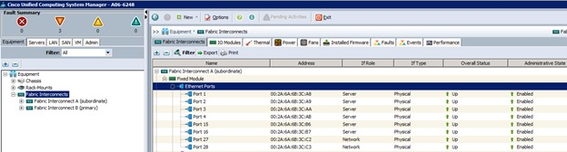
8. Click Yes to confirm uplink ports and click OK.
9. Select Equipment > Fabric Interconnects > Fabric Interconnect B (subordinate) > Fixed Module.
10. Expand Ethernet Ports.
11. Select the ports that are connected to the chassis, C-series servers or to the Cisco 2232 FEX (two per FEX), right-click them, and select Configure as Server Port.
12. Click Yes to confirm server ports and click OK.
13. Select ports 27 and 28 that are connected to the Cisco Nexus switches, right-click them, and select Configure as Uplink Port.
14. Click Yes to confirm the uplink ports and click OK.
15. Select port 29 connected to out of band management network switch on each Fabric Interconnect and select Configure as Uplink Port.
16. Click Yes to confirm the uplink ports and click OK.
17. Optional: If the out of band management switch is 1Gbps switch, for the port 29 on each Fabric Interconnect, right click the interface and select Show Navigator.
18. Click Show Interface in the Properties window.
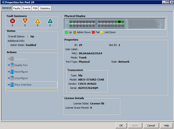
19. Select 1Gbps as the speed of the interface.
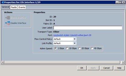
Acknowledge Cisco UCS Chassis and FEX
To acknowledge all Cisco UCS chassis and external 2232 FEX modules, complete the following steps:
1. In Cisco UCS Manager, click the Equipment tab in the navigation pane.
2. Expand Chassis and select each chassis that is listed.
3. Right-click each chassis and select Acknowledge Chassis.
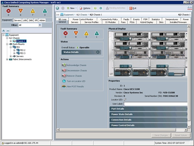
4. Click Yes and then click OK to complete acknowledging the chassis.
5. If Nexus 2232 FEX is part of the configuration, expand Rack Mounts and FEX.
6. Right-click each FEX that is listed and select Acknowledge FEX.
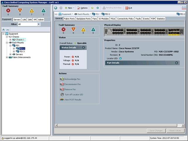
7. Click Yes and then click OK to complete acknowledging the FEX.
Create Uplink Port Channels to Cisco Nexus Switches
To configure the necessary port channels out of the Cisco UCS environment, complete the following steps:
1. In Cisco UCS Manager, click the LAN tab in the navigation pane.
![]() Note: In this procedure, two port channels are created: one from fabric A to both Cisco Nexus switches and one from fabric B to both Cisco Nexus switches.
Note: In this procedure, two port channels are created: one from fabric A to both Cisco Nexus switches and one from fabric B to both Cisco Nexus switches.
2. Under LAN > LAN Cloud, expand the Fabric A tree.
3. Right-click Port Channels.
4. Select Create Port Channel.
5. Enter 13 as the unique ID of the port channel.
6. Enter vPC-13-Nexus as the name of the port channel.
7. Click Next.
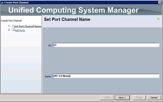
8. Select the following ports to be added to the port channel:
— Slot ID 1 and port 27
— Slot ID 1 and port 28
9. Click >> to add the ports to the port channel.
10. Click Finish to create the port channel.
11. Click OK.
12. In the navigation pane, under LAN > LAN Cloud, expand the fabric B tree.
13. Right-click Port Channels.
14. Select Create Port Channel.
15. Enter 14 as the unique ID of the port channel.
16. Enter vPC-14-NEXUS as the name of the port channel.
17. Click Next.
18. Select the following ports to be added to the port channel:
— Slot ID 1 and port 27
— Slot ID 1 and port 28
19. Click >> to add the ports to the port channel.
20. Click Finish to create the port channel.
21. Click OK.
Create MAC Address Pools
To configure the necessary MAC address pools for the Cisco UCS environment, complete the following steps:
1. In Cisco UCS Manager, click the LAN tab in the navigation pane.
2. Select Pools > root.
![]() Note: In this procedure, two MAC address pools are created, one for each switching fabric.
Note: In this procedure, two MAC address pools are created, one for each switching fabric.
3. Right-click MAC Pools under the root organization.
4. Select Create MAC Pool to create the MAC address pool.
5. Enter MAC_Pool_A as the name of the MAC pool.
6. Optional: Enter a description for the MAC pool.
7. Click Next.
8. Click Add.
9. Specify a starting MAC address.
![]() Note: For the FlexPod solution, the recommendation is to place 0A in the next-to-last octet of the starting MAC address to identify all of the MAC addresses as fabric A addresses.
Note: For the FlexPod solution, the recommendation is to place 0A in the next-to-last octet of the starting MAC address to identify all of the MAC addresses as fabric A addresses.
10. Specify a size for the MAC address pool that is sufficient to support the available blade or server resources.
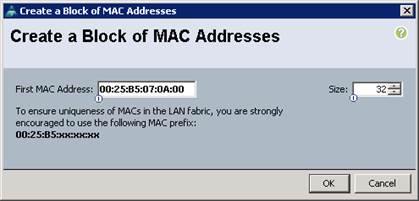
11. Click OK.
12. Click Finish.
13. In the confirmation message, click OK.
14. Right-click MAC Pools under the root organization.
15. Select Create MAC Pool to create the MAC address pool.
16. Enter MAC_Pool_B as the name of the MAC pool.
17. Optional: Enter a description for the MAC pool.
18. Click Next.
19. Click Add.
20. Specify a starting MAC address.
![]() Note: For the FlexPod solution, it is recommended to place 0B in the next to last octet of the starting MAC address to identify all the MAC addresses in this pool as fabric B addresses.
Note: For the FlexPod solution, it is recommended to place 0B in the next to last octet of the starting MAC address to identify all the MAC addresses in this pool as fabric B addresses.
21. Specify a size for the MAC address pool that is sufficient to support the available blade or server resources.
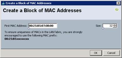
22. Click OK.
23. Click Finish.
24. In the confirmation message, click OK.
Create IQN Pools for iSCSI Boot
To configure the necessary IQN pools for the Cisco UCS environment, complete the following steps.
1. In the UCS Manager, select the SAN tab on the left.
2. Select Pools > root.
3. Right-click IQN Pools under the root organization.
4. Select Create IQN Suffix Pool to create the IQN pool.
5. Enter IQN_Pool for the name of the IQN pool.
6. Optional: Enter a description for the IQN pool.
7. Enter iqn.1992-08.com.cisco as the prefix
8. Select Sequential for Assignment Order.
9. Click Next.
10. Click Add.
11. Enter ucs-host as the suffix.
12. Enter 1 in the From field.
13. Specify a size of the IQN block sufficient to support the available server resources.
14. Click OK.
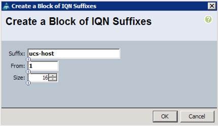
15. Click Finish.
16. In the message box that displays, click OK.
Create IP Pools for iSCSI Boot
To configure the necessary IP pools iSCSI boot for the Cisco UCS environment, complete the following steps:
1. In Cisco UCS Manager, select the LAN tab on the left.
2. Select Pools > root.
3. Two IP pools are created, one for each switching fabric.
4. Right-click IP Pools under the root organization.
5. Select Create IP Pool to create the IP pool.
6. Enter iSCSI_IP_Pool_A for the name of the IP pool.
7. Optional: Enter a description of the IQN pool.
8. Select Sequential for Assignment Order.
9. Click Next.
10. Click Add.
11. In the From field, enter the beginning of the range to assign as iSCSI IP addresses.
12. Set the size to enough addresses to accommodate the servers.
13. Click OK.
14. Click Finish.
15. Right-click IP Pools under the root organization.
16. Select Create IP Pool to create the IP pool.
17. Enter iSCSI_IP_Pool_B for the name of the IP pool.
18. Optional: Enter a description of the IQN pool.
19. Select Sequential for Assignment Order.
20. Click Next.
21. Click Add.
22. In the From field, enter the beginning of the range to assign as iSCSI IP addresses.
23. Set the size to enough addresses to accommodate the servers.
24. Click OK.
25. Click Finish.
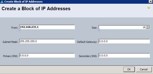
Create UUID Suffix Pool
To configure the necessary universally unique identifier (UUID) suffix pool for the Cisco UCS environment, complete the following steps:
1. In Cisco UCS Manager, click the Servers tab in the navigation pane.
2. Select Pools > root.
3. Right-click UUID Suffix Pools.
4. Select Create UUID Suffix Pool.
5. Enter UUID_Pool as the name of the UUID suffix pool.
6. Optional: Enter a description for the UUID suffix pool.
7. Keep the prefix at the derived option.
8. Click Next.
9. Click Add to add a block of UUIDs.
10. Keep the From field at the default setting.
11. Specify a size for the UUID block that is sufficient to support the available blade or server resources.
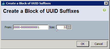
12. Click OK.
13. Click Finish.
14. Click OK.
Create Server Pool
To configure the necessary server pool for the Cisco UCS environment, complete the following steps:
1. Consider creating unique server pools to achieve the granularity that is required in your environment.
2. In Cisco UCS Manager, click the Servers tab in the navigation pane.
3. Select Pools > root.
4. Right-click Server Pools.
5. Select Create Server Pool.
6. Enter Infra_Pool as the name of the server pool.
7. Optional: Enter a description for the server pool.
8. Click Next.
9. Select two (or more) servers to be used for the VMware management cluster and click >> to add them to the Infra_Pool server pool.
10. Click Finish.
11. Click OK.
Create VLANs
To configure the necessary virtual local area networks (VLANs) for the Cisco UCS environment, complete the following steps:
1. In Cisco UCS Manager, click the LAN tab in the navigation pane.
![]() Note: In this procedure, four unique VLANs and a range of 100 VLANs for APIC are created. The VLAN IDs used in this step are shown in Table 2.
Note: In this procedure, four unique VLANs and a range of 100 VLANs for APIC are created. The VLAN IDs used in this step are shown in Table 2.
2. Select LAN > LAN Cloud.
3. Right-click VLANs.
4. Select Create VLANs.
5. Enter Native-VLAN as the name of the VLAN to be used as the native VLAN.
6. Keep the Common/Global option selected for the scope of the VLAN.
7. Enter the <2> as the ID of the native VLAN.
8. Keep the Sharing Type as None.
9. Click OK, and then click OK again.
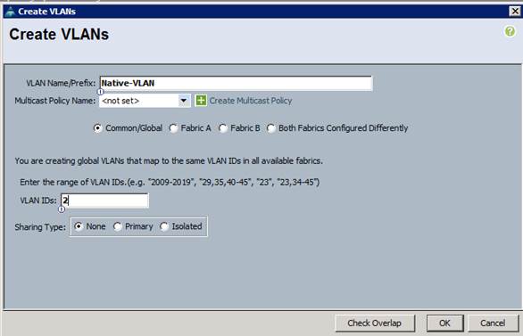
10. Expand the list of VLANs in the navigation pane, right-click the newly created Native-VLAN and select Set as Native VLAN.
11. Click Yes, and then click OK.
12. Right-click VLANs.
13. Select Create VLANs.
14. Enter iSCSI-A-VLAN as the name of the VLAN to be used for the first iSCSI VLAN.
15. Keep the Common/Global option selected for the scope of the VLAN.
16. Enter the VLAN ID for the first iSCSI VLAN.
17. Click OK, then OK.

18. Right-click VLANs.
19. Select Create VLANs.
20. Enter iSCSI-B-VLAN as the name of the VLAN to be used for the second iSCSI VLAN.
21. Keep the Common/Global option selected for the scope of the VLAN.
22. Enter the VLAN ID for the second iSCSI VLAN.
23. Click OK, then OK.
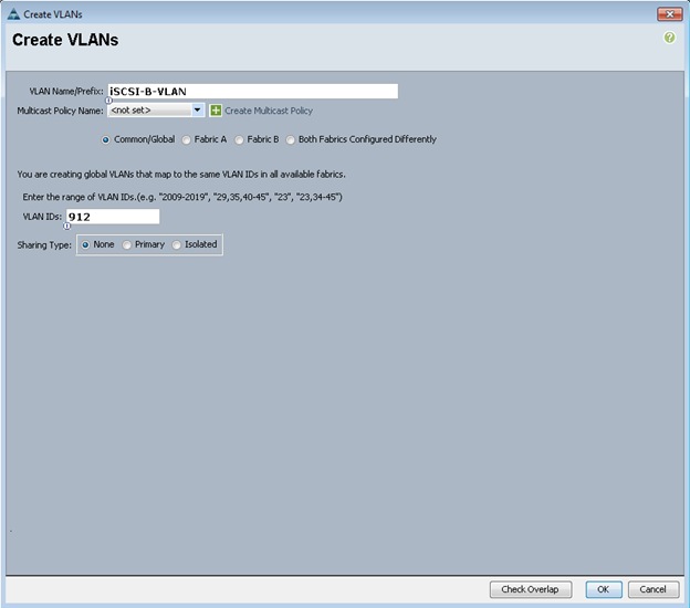
24. Right-click VLANs.
25. Select Create VLANs.
26. Enter OOB-Mgmt as the name of the VLAN to be used for management traffic.
27. Keep the Common/Global option selected for the scope of the VLAN.
28. Enter <3177> as the ID of the management VLAN.
29. Keep the Sharing Type as None.
30. Click OK, and then click OK again.
31. Right-click VLANs.
32. Select Create VLANs.
33. Enter INFRA-NFS as the name of the VLAN to be used for NFS VMk ports.
34. Keep the Common/Global option selected for the scope of the VLAN.
35. Enter the <3270> for the NFS VLAN.
36. Keep the Sharing Type as None.
37. Click OK, and then click OK again.
38. Right-click VLANs.
39. Select Create VLANs.
40. Enter APIC- as the prefix of the VLAN to be used for APIC.
41. Keep the Common/Global option selected for the scope of the VLAN.
42. Enter the <1101-1200> for VLAN IDs.
43. Keep the Sharing Type as None.
44. Click OK, and then click OK again.
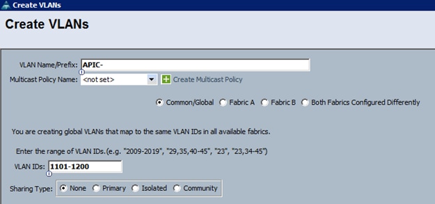
Create VLAN Groups
To configure split layer-2 domain in UCS, two VLAN groups need to be created and attached to different uplink ports. In the procedure below, a VLAN group OOB-Mgmt is configured only with out of band management VLAN (3177) and is attached to port 19 on each Fabric Interconnect. VLAN group Uplink-PortChannel is configured to carry all the remaining VLANs and is attached to port-channel 13 and 14. To create the VLAN groups, complete the following steps:
1. In Cisco UCS Manager, click the LAN tab in the navigation pane.
2. Select LAN > LAN Cloud.
3. Right-click VLAN Groups.
4. Select Create VLAN Group.
5. Use OOB-Mgmt as the VLAN Group Name
6. Select the Native-VLAN (2) and OOB-Mgmt VLAN (3177). Click the radio button to set Native-VLAN as native VLAN.
7. Click Next to add Uplink Ports. Select Port 29 on both Fabric Interconnect A and B.
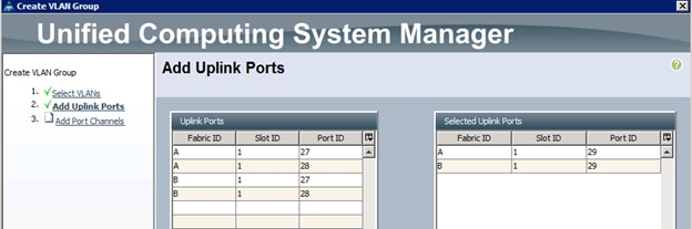
8. Click Finish.
9. Right-click VLAN Groups.
10. Select Create VLAN Group.
11. Use Uplink-PortChannel as the VLAN Group Name.
12. Select the Infra-NFS (3270), iSCSI-A-VLAN (911), iSCSI-B-VLAN (912) and APIC-1101 through APIC-1200 (all 100) VLANs.
13. Click Next twice to add Uplink Port Channels. Select Port Channel 13 and 14.
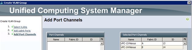
14. Click Finish.
Create Host Firmware Package
Firmware management policies allow the administrator to select the corresponding packages for a given server configuration. These policies often include packages for adapter, BIOS, board controller, FC adapters, host bus adapter (HBA) option ROM, and storage controller properties.
To create a firmware management policy for a given server configuration in the Cisco UCS environment, complete the following steps:
1. In Cisco UCS Manager, click the Servers tab in the navigation pane.
2. Select Policies > root.
3. Right-click Host Firmware Packages.
4. Select Create Host Firmware Package.
5. Enter VM-Host-Infra as the name of the host firmware package.
6. Leave Simple selected.
7. Select the version 2.2(3d) for both the Blade and Rack Packages.
8. Click OK to create the host firmware package.
9. Click OK.
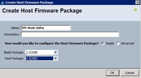
Set Jumbo Frames in Cisco UCS Fabric
To configure jumbo frames and enable quality of service in the Cisco UCS fabric, complete the following steps:
1. In Cisco UCS Manager, click the LAN tab in the navigation pane.
2. Select LAN > LAN Cloud > QoS System Class.
3. In the right pane, click the General tab.
4. On the Best Effort row, enter 9216 in the box under the MTU column.
5. Click Save Changes in the bottom of the window.
6. Click OK.
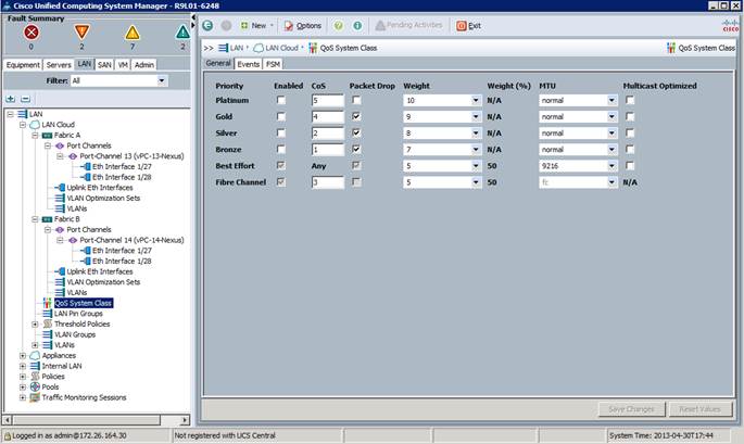
Create Local Disk Configuration Policy (Optional)
A local disk configuration for the Cisco UCS environment is necessary if the servers in the environment do not have a local disk.
This policy should not be used on servers that contain local disks.
To create a local disk configuration policy, complete the following steps:
1. In Cisco UCS Manager, click the Servers tab in the navigation pane.
2. Select Policies > root.
3. Right-click Local Disk Config Policies.
4. Select Create Local Disk Configuration Policy.
5. Enter iSCSI-Boot as the local disk configuration policy name.
6. Change the mode to No Local Storage.
7. Click OK to create the local disk configuration policy.
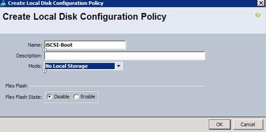
8. Click OK.
Create Network Control Policy for Cisco Discovery Protocol
To create a network control policy that enables Cisco Discovery Protocol (CDP) on virtual network ports, complete the following steps:
1. In Cisco UCS Manager, click the LAN tab in the navigation pane.
2. Select Policies > root.
3. Right-click Network Control Policies.
4. Select Create Network Control Policy.
5. Enter Enable_CDP as the policy name.
6. For CDP, select the Enabled option.
7. Click OK to create the network control policy.
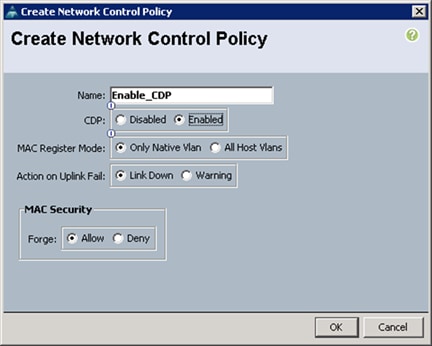
8. Click OK.
Create Power Control Policy
To create a power control policy for the Cisco UCS environment, complete the following steps:
1. In Cisco UCS Manager, click the Servers tab in the navigation pane.
2. Select Policies > root.
3. Right-click Power Control Policies.
4. Select Create Power Control Policy.
5. Enter No-Power-Cap as the power control policy name.
6. Change the power capping setting to No Cap.
7. Click OK to create the power control policy.
8. Click OK.
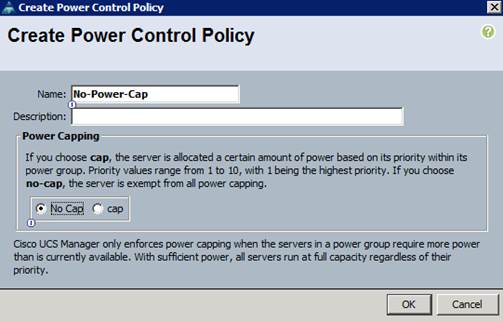
Create Server Pool Qualification Policy (Optional)
To create an optional server pool qualification policy for the Cisco UCS environment, complete the following steps:
![]() Note: This example creates a policy for a Cisco UCS B200-M3 server.
Note: This example creates a policy for a Cisco UCS B200-M3 server.
1. In Cisco UCS Manager, click the Servers tab in the navigation pane.
2. Select Policies > root.
3. Right-click Server Pool Policy Qualifications.
4. Select Create Server Pool Policy Qualification.
5. Enter UCSB-B200-M3 as the name for the policy.
6. Select Create Server PID Qualifications.
7. Enter UCSB-B200-M3 as the PID.
8. Click OK to create the server pool qualification policy.
9. Click OK, and then click OK again.
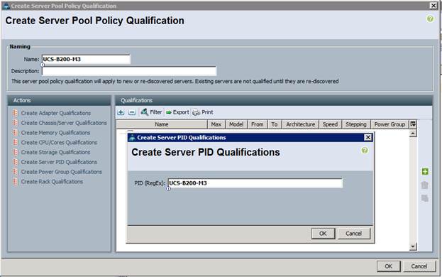
Create Server BIOS Policy
To create a server BIOS policy for the Cisco UCS environment, complete the following steps:
1. In Cisco UCS Manager, click the Servers tab in the navigation pane.
2. Select Policies > root.
3. Right-click BIOS Policies.
4. Select Create BIOS Policy.
5. Enter VM-Host-Infra as the BIOS policy name.
6. Change the Quiet Boot setting to Disabled.
7. Click Finish to create the BIOS policy.
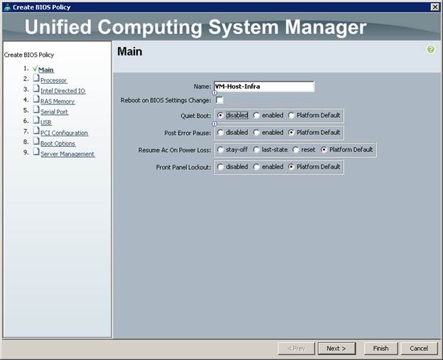
8. Click OK.
Create vNIC/vHBA Placement Policy for Virtual Machine Infrastructure Hosts
To create a vNIC/vHBA placement policy for the infrastructure hosts, complete the following steps:
1. In Cisco UCS Manager, click the Servers tab in the navigation pane.
2. Select Policies > root.
3. Right-click vNIC/vHBA Placement Policies.
4. Select Create Placement Policy.
5. Enter VM-Host-Infra as the name of the placement policy.
6. Click 1 and select Assigned Only.
7. Click OK, and then click OK again.
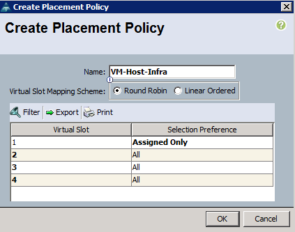
Update Default Maintenance Policy
To update the default Maintenance Policy, complete the following steps:
1. In Cisco UCS Manager, click the Servers tab in the navigation pane.
2. Select Policies > root.
3. Select Maintenance Policies > default.
4. Change the Reboot Policy to User Ack.
5. Click Save Changes.
6. Click OK to accept the change.
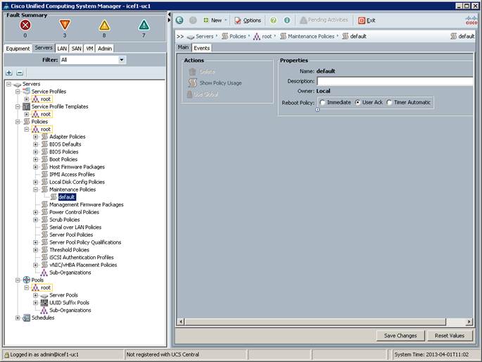
Create vNIC Templates
A total of 8 vNIC Templates will be created. Infrastructure ESXi hosts use all 8 templates (8 vNICS) while the application ESXi servers utilize only six (6 vNICs). To create multiple virtual network interface card (vNIC) templates for the Cisco UCS environment, complete the following steps.
Create Data vNICs
1. In Cisco UCS Manager, click the LAN tab in the navigation pane.
2. Select Policies > root.
3. Right-click vNIC Templates.
4. Select Create vNIC Template.
5. Enter vNIC_Template_A as the vNIC template name.
6. Keep Fabric A selected.
7. Do not select the Enable Failover checkbox.
8. Under Target, make sure that the VM checkbox is not selected.
9. Select Updating Template as the Template Type.
10. Under VLANs, select the checkboxes for APIC-1101 through APIC-1200, and default VLANs.
11. Set default as the native VLAN.
12. For MTU, enter 9000.
13. In the MAC Pool list, select MAC_Pool_A.
14. In the Network Control Policy list, select Enable_CDP.
15. Click OK to create the vNIC template.
16. Click OK.
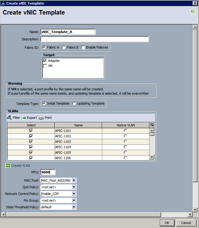
17. In the navigation pane, select the LAN tab.
18. Select Policies > root.
19. Right-click vNIC Templates.
20. Select Create vNIC Template
21. Enter vNIC_Template_B as the vNIC template name.
22. Select Fabric B.
23. Do not select the Enable Failover checkbox.
24. Under Target, make sure the VM checkbox is not selected.
25. Select Updating Template as the template type.
26. Under VLANs, select the checkboxes for APIC-1101 through APIC-1200, and default VLANs.
27. Set default as the native VLAN.
28. For MTU, enter 9000.
29. In the MAC Pool list, select MAC_Pool_B.
30. In the Network Control Policy list, select Enable_CDP.
31. Click OK to create the vNIC template.
32. Click OK.
Create iSCSI vNICSs
1. Select the LAN tab on the left.
2. Select Policies > root.
3. Right-click vNIC Templates.
4. Select Create vNIC Template.
5. Enter iSCSI_Template_A as the vNIC template name.
6. Leave Fabric A selected. Do not select the Enable Failover checkbox.
7. Under Target, make sure that the VM checkbox is not selected.
8. Select Updating Template for Template Type.
9. Under VLANs, select iSCSI-A-VLAN (911).
10. Set iSCSI-A-VLAN as the native VLAN.
11. Under MTU, enter 9000.
12. From the MAC Pool list, select MAC_Pool_A.
13. From the Network Control Policy list, select Enable_CDP.
14. Click OK to complete creating the vNIC template.
15. Click OK.
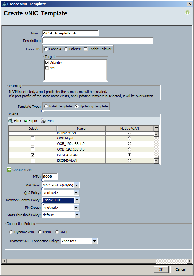
16. Select the LAN tab on the left.
17. Select Policies > root.
18. Right-click vNIC Templates.
19. Select Create vNIC Template.
20. Enter iSCSI_Template_B as the vNIC template name.
21. Select Fabric B. Do not select the Enable Failover checkbox.
22. Under Target, make sure that the VM checkbox is not selected.
23. Select Updating Template for Template Type.
24. Under VLANs, select iSCSI-B-VLAN (912).
25. Set iSCSI-B-VLAN as the native VLAN.
26. Under MTU, enter 9000.
27. From the MAC Pool list, select MAC_Pool_B.
28. From the Network Control Policy list, select Enable_CDP.
29. Click OK to complete creating the vNIC template.
30. Click OK.
Create OOB Mgmt vNICSs
1. Select the LAN tab on the left.
2. Select Policies > root.
3. Right-click vNIC Templates.
4. Select Create vNIC Template.
5. Enter OOB-A as the vNIC template name.
6. Leave Fabric A selected. Do not select the Enable Failover checkbox.
7. Under Target, make sure that the VM checkbox is not selected.
8. Select Updating Template for Template Type.
9. Under VLANs, select OOB-Mgmt VLAN and Native-VLAN.
10. Set Native-VLAN as the native VLAN.
11. Under MTU, enter 1500. From the MAC Pool list, select MAC_Pool_A.
12. From the Network Control Policy list, select Enable_CDP.
13. Click OK to complete creating the vNIC template.
14. Click OK.
15. Select the LAN tab on the left.
16. Select Policies > root.
17. Right-click vNIC Templates.
18. Select Create vNIC Template.
19. Enter OOB-B as the vNIC template name.
20. Select Fabric B. Do not select the Enable Failover checkbox.
21. Under Target, make sure that the VM checkbox is not selected.
22. Select Updating Template for Template Type.
23. Under VLANs, select OOB-Mgmt VLAN and Native-VLAN.
24. Set Native-VLAN as the native VLAN.
25. Under MTU, enter 1500. From the MAC Pool list, select MAC_Pool_B.
26. From the Network Control Policy list, select Enable_CDP.
27. Click OK to complete creating the vNIC template.
28. Click OK.
Create Infrastructure NFS vNICSs
![]() Note: These vNICs will only be utilized on ESXi servers hosting Infrastructure services
Note: These vNICs will only be utilized on ESXi servers hosting Infrastructure services
1. Select the LAN tab on the left.
2. Select Policies > root.
3. Right-click vNIC Templates.
4. Select Create vNIC Template.
5. Enter Infra_NFS_A as the vNIC template name.
6. Leave Fabric A selected. Do not select the Enable Failover checkbox.
7. Under Target, make sure that the VM checkbox is not selected.
8. Select Updating Template for Template Type.
9. Under VLANs, select Infra-NFS (3270) VLAN and default.
10. Set default as the native VLAN.
11. Under MTU, enter 9000. From the MAC Pool list, select MAC_Pool_A.
12. From the Network Control Policy list, select Enable_CDP.
13. Click OK to complete creating the vNIC template.
14. Click OK.
15. Select the LAN tab on the left.
16. Select Policies > root.
17. Right-click vNIC Templates.
18. Select Create vNIC Template.
19. Enter Infra_NFS_B as the vNIC template name.
20. Select Fabric B. Do not select the Enable Failover checkbox.
21. Under Target, make sure that the VM checkbox is not selected.
22. Select Updating Template for Template Type.
23. Under VLANs, select Infra-NFS VLAN and default VLAN.
24. Set default as the native VLAN.
25. Under MTU, enter 9000. From the MAC Pool list, select MAC_Pool_B.
26. From the Network Control Policy list, select Enable_CDP.
27. Click OK to complete creating the vNIC template.
28. Click OK.
![]() Note: At the end of the vNIC template creation, there should be 8 vNIC templates available in the UCS Manager as shown in Figure 3 below.
Note: At the end of the vNIC template creation, there should be 8 vNIC templates available in the UCS Manager as shown in Figure 3 below.
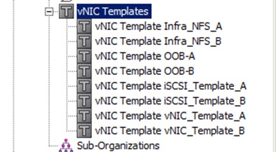
Create Boot Policies
This procedure applies to a Cisco UCS environment in which two iSCSI logical interfaces (LIFs) are on cluster node 1 (iscsi lif01a and iscsi lif01b) and two iSCSI LIFs are on cluster node 2 (iscsi lif02a and iscsi lif02b). One boot policy is configured in this procedure. This policy configures the primary target to be iscsi_lif01a.
To create boot policies for the Cisco UCS environment, complete the following steps:
1. In Cisco UCS Manager, click the Servers tab in the navigation pane.
2. Select Policies > root.
3. Right-click Boot Policies.
4. Select Create Boot Policy.
5. Enter Boot-Fabric-A as the name of the boot policy.
6. Optional: Enter a description for the boot policy.
7. Keep the Reboot on Boot Order Change option cleared.
8. Expand the Local Devices drop-down menu and select Add CD-ROM.
9. Expand the iSCSI vNICs section and select Add iSCSI Boot.
10. In the Add iSCSI Boot dialog box, enter iSCSI-A-vNIC.
11. Click OK.
12. Select Add iSCSI Boot.
13. In the Add iSCSI Boot dialog box, enter iSCSI-B-vNIC.
14. Click OK.
15. Click OK to save the boot policy. Click OK to close the Boot Policy window.
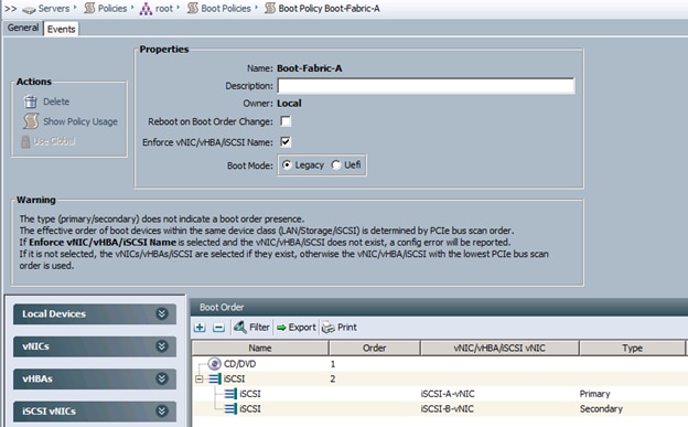
Create Service Profile Template
In this procedure, one service profile template for Infrastructure ESXi hosts is created for fabric A boot.
To create the service profile template, complete the following steps:
1. In Cisco UCS Manager, click the Servers tab in the navigation pane.
2. Select Service Profile Templates > root.
3. Right-click root.
4. Select Create Service Profile Template to open the Create Service Profile Template wizard.
5. Identify the service profile template:
6. Enter VM-Host-Infra-Fabric-A as the name of the service profile template. This service profile template is configured to boot from node 1 on fabric A.
7. Select the Updating Template option.
8. Under UUID, select UUID_Pool as the UUID pool.
9. Click Next.
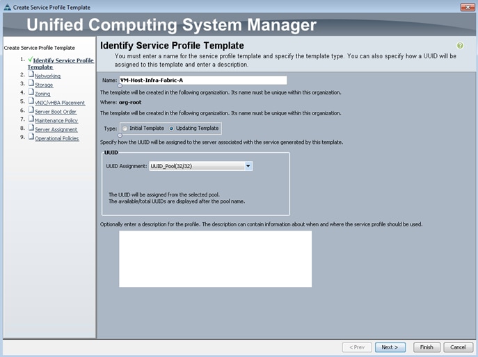
![]() Note: To configure the networking options, 8 vNIC interfaces will be added for Infrastructure ESXi hosts:
Note: To configure the networking options, 8 vNIC interfaces will be added for Infrastructure ESXi hosts:
Configure Networking options:
1. Keep the default setting for Dynamic vNIC Connection Policy.
2. Select the Expert option to configure the LAN connectivity.
3. Click the upper Add button to add a vNIC to the template.
4. In the Create vNIC dialog box, enter vNIC-A as the name of the vNIC.
5. Select the Use vNIC Template checkbox.
6. In the vNIC Template list, select vNIC_Template_A.
7. In the Adapter Policy list, select VMWare.
8. Click OK to add this vNIC to the template.
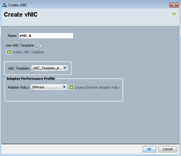
9. On the Networking page of the wizard, click the upper Add button to add another vNIC to the template.
10. In the Create vNIC box, enter vNIC-B as the name of the vNIC.
11. Select the Use vNIC Template checkbox.
12. In the vNIC Template list, select vNIC_Template_B.
13. In the Adapter Policy list, select VMWare.
14. Click OK to add the vNIC to the template.
15. Click the upper Add button to add a vNIC to the template.
16. In the Create vNIC dialog box, enter iSCSI-A-vNIC as the name of the vNIC.
17. Select the Use vNIC Template checkbox.
18. In the vNIC Template list, select iSCSI_Template_A.
19. In the Adapter Policy list, select VMWare.
20. Click OK to add this vNIC to the template.
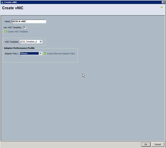
21. Click the upper Add button to add a vNIC to the template.
22. In the Create vNIC dialog box, enter iSCSI-B-vNIC as the name of the vNIC.
23. Select the Use vNIC Template checkbox.
24. In the vNIC Template list, select iSCSI_Template_B.
25. In the Adapter Policy list, select VMWare.
26. Click OK to add this vNIC to the template.
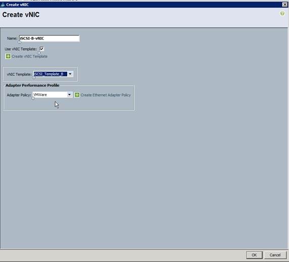
27. On the Networking page of the wizard, click the upper Add button to add another vNIC to the template.
28. In the Create vNIC box, enter OOB-A as the name of the vNIC.
29. Select the Use vNIC Template checkbox.
30. In the vNIC Template list, select OOB-A.
31. In the Adapter Policy list, select VMWare.
32. Click OK to add the vNIC to the template.
33. On the Networking page of the wizard, click the upper Add button to add another vNIC to the template.
34. In the Create vNIC box, enter OOB-B as the name of the vNIC.
35. Select the Use vNIC Template checkbox.
36. In the vNIC Template list, select OOB-B.
37. In the Adapter Policy list, select VMWare.
38. Click OK to add the vNIC to the template.
![]() Note: The next two vNIC interfaces are only needed for Infrastructure ESXi Hosts. These interfaces enable NFS access using NFS specific vSwitch and static EPG mapping. ESXi servers not hosting infrastructure VMs, use VDS for NFS access to application specific SVMs.
Note: The next two vNIC interfaces are only needed for Infrastructure ESXi Hosts. These interfaces enable NFS access using NFS specific vSwitch and static EPG mapping. ESXi servers not hosting infrastructure VMs, use VDS for NFS access to application specific SVMs.
39. On the Networking page of the wizard, click the upper Add button to add another vNIC to the template.
40. In the Create vNIC box, enter NFS-A as the name of the vNIC.
41. Select the Use vNIC Template checkbox.
42. In the vNIC Template list, select Infra_NFS_A.
43. In the Adapter Policy list, select VMWare.
44. Click OK to add the vNIC to the template.
45. On the Networking page of the wizard, click the upper Add button to add another vNIC to the template.
46. In the Create vNIC box, enter NFS-B as the name of the vNIC.
47. Select the Use vNIC Template checkbox.
48. In the vNIC Template list, select Infra_NFS_B.
49. In the Adapter Policy list, select VMWare.
50. Click OK to add the vNIC to the template.
51. Verify 8 vNIC interfaces are present.
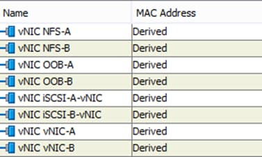
52. Expand the iSCSI vNICs section (if not already expanded).
53. Select iqn-pool under Initiator Name Assignment.
54. Click the lower Add button in the iSCSI vNIC section to define a vNIC.
55. Enter iSCSI-A-vNIC as the name of the vNIC.
56. Select iSCSI-A-vNIC for Overlay vNIC.
57. Set the iSCSI Adapter Policy to default.
58. Set the VLAN to iSCSI-A-VLAN.
59. Leave the MAC Address set to None.
60. Click OK.

61. Click the lower Add button in the iSCSI vNIC section to define a vNIC.
62. Enter iSCSI-B-vNIC as the name of the vNIC.
63. Set the Overlay vNIC to iSCSI-B-vNIC
64. Set the iSCSI Adapter Policy to default.
65. Set the VLAN to iSCSI-B-VLAN
66. Leave the MAC Address set to None.
67. Click OK.
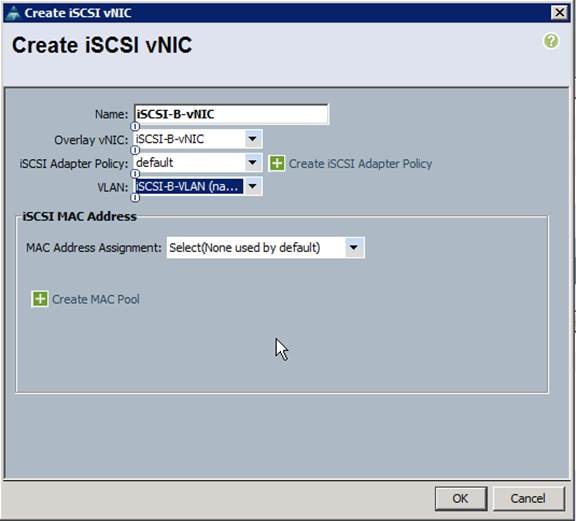
68. Click OK.
69. Review the table in the Networking page to make sure that all vNICs were created.
70. Click Next.
Configure Storage options:
1. Select a local disk configuration policy:
If the server in question has local disks, select default in the Local Storage list.
If the server in question does not have local disks, select iSCSI-Boot.
2. Select the No vHBAs option for the How would you like to configure SAN connectivity? field.
3. Click Next.
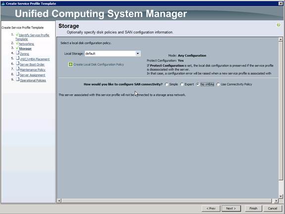
Configure Zoning Options
1. Set no Zoning options and click Next.
Configure vNIC/HBA Placement
1. Set the vNIC/vHBA placement options (Figure 22).
2. In the Select Placement list, select the VM-Host-Infra placement policy.
3. Select vCon1 and assign the vHBAs/vNICs to the virtual network interfaces policy in the following order:
— vNIC-A
— vNIC-B
— iSCSI-vNIC-A
— iSCSI-vNIC-B
— OOB-A
— OOB-B
— NFS-A
— NFS-B
4. Review the table to verify that all vNICs and vHBAs were assigned to the policy in the appropriate order.
5. Click Next.
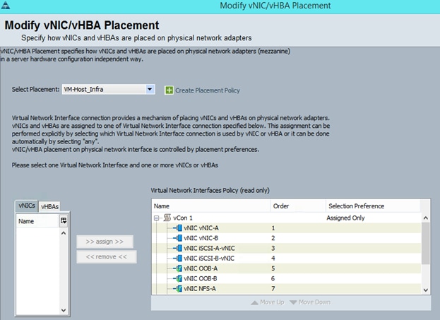
Configure Server Boot Order
1. Select Boot-Fabric-A for Boot Policy.
2. In the Boot Order pane, select iSCSI-A-vNIC.
3. Click the Set iSCSI Boot Parameters button.
4. Leave the Set iSCSI Boot Parameters dialog box <not set> to use the single Service Profile Initiator Name defined in the previous steps.
5. Set iSCSI_IP_Pool_A as the Initiator IP address Policy.
6. Keep the iSCSI Static Target Interface button selected and click the ![]() button.
button.
7. Log in to the storage cluster management interface and run the following command:
iscsi nodename
8. Note or copy the iSCSI target name for Infra-SVM.
9. In the Create iSCSI Static Target dialog box, paste the iSCSI target node name from Infra-SVM.
10. Enter the IP address of iSCSI_lif02a for the IPv4 Address field.
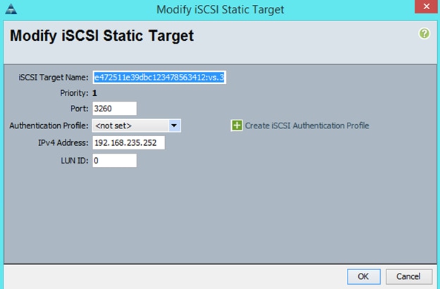
11. Click OK to add the iSCSI static target.
12. Keep the iSCSI Static Target Interface option selected and click the ![]() button.
button.
13. In the Create iSCSI Static Target window, paste the iSCSI target node name from Infra-SVM into the iSCSI Target Name field.
14. Enter the IP address of iscsi_lif01a in the IPv4 Address field.
15. Click OK.
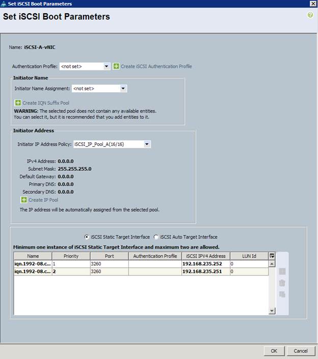
16. Click OK.
17. In the Boot Order pane, select iSCSI-vNIC-B.
18. Click the Set iSCSI Boot Parameters button.
19. In the Set iSCSI Boot Parameters dialog box, set the leave the Initiator Name Assignment to <not set>.
20. In the Set iSCSI Boot Parameters dialog box, set the initiator IP address policy to iSCSI_IP_Pool_B.
21. Keep the iSCSI Static Target Interface option selected and click the ![]() button.
button.
22. In the Create iSCSI Static Target window, paste the iSCSI target node name from Infra-SVM into the iSCSI Target Name field (same target name as above).
23. Enter the IP address of iscsi_lif02b in the IPv4 address field.
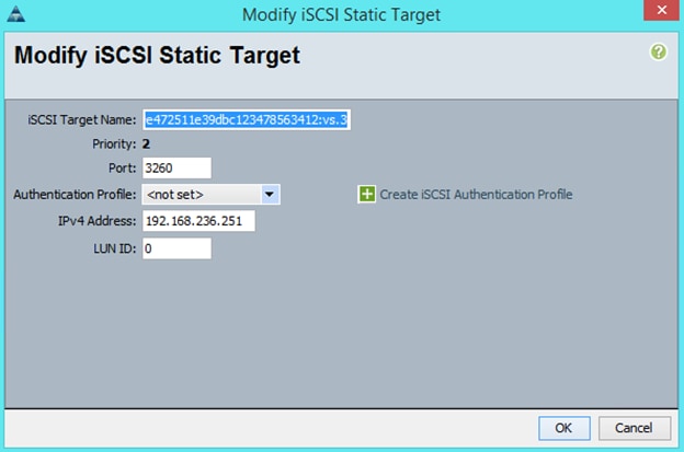
24. Click OK to add the iSCSI static target.
25. Keep the iSCSI Static Target Interface option selected and click the ![]() button.
button.
26. In the Create iSCSI Static Target dialog box, paste the iSCSI target node name from Infra-SVM into the iSCSI Target Name field.
27. Enter the IP address of iscsi_lif01b in the IPv4 Address field.
28. Click OK.
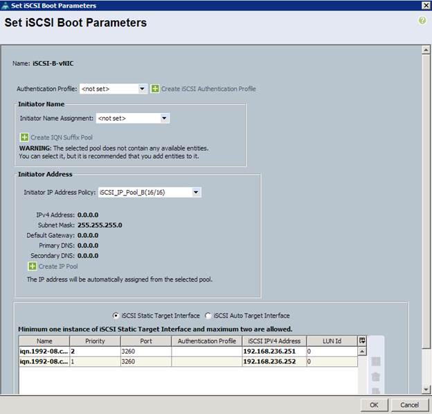
29. Click OK.
30. Review the table to make sure that all boot devices were created and identified. Verify that the boot devices are in the correct boot sequence.
31. Click Next to continue to the next section.
Configure Maintenance Policy
1. Select the default Maintenance Policy.
2. Click Next.
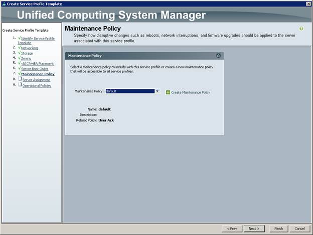
Configure Server Assignment
1. In the Pool Assignment list, select Infra_Pool.
2. Optional: Select a Server Pool Qualification policy.
3. Select Down as the power state to be applied when the profile is associated with the server.
4. Expand Firmware Management at the bottom of the page and select VM-Host-Infra from the Host Firmware list.
5. Click Next.
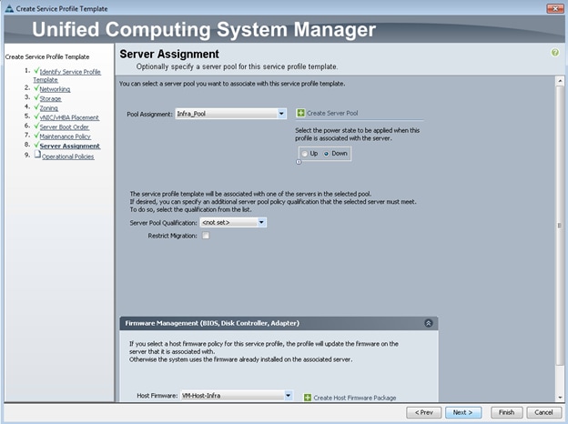
Configure Operational Policies
1. In the BIOS Policy list, select VM-Host-Infra.
2. Expand Power Control Policy Configuration and select No-Power-Cap in the Power Control Policy list.
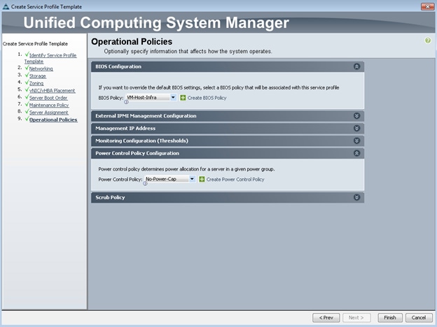
3. Click Finish to create the service profile template.
4. Click OK in the confirmation message.
Create Service Profiles
To create service profiles from the service profile template, complete the following steps:
1. In Cisco UCS Manager, click the Servers tab in the navigation pane.
2. Select Service Profile Templates > root > Service Template VM-Host-Infra-Fabric-A.
3. Right-click VM-Host-Infra-Fabric-A and select Create Service Profiles from Template.
4. Enter VM-Host-Infra-0 as the service profile prefix.
5. Enter 1 as Name Suffix Starting Number.
6. Enter 1 as the Number of Instances.
7. Click OK to create the service profile.
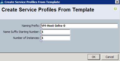
8. Click OK in the confirmation message.
Add More Servers to FlexPod Unit
Additional server pools, service profile templates, and service profiles can be created in the respective organizations to add more servers to the FlexPod unit. All other pools and policies are at the root level and can be shared among the organizations.
Gather Necessary Information
After the Cisco UCS service profiles have been created, each infrastructure blade in the environment will have a unique configuration. To proceed with the FlexPod deployment, specific information must be gathered from each Cisco UCS blade and from the NetApp controllers. Insert the required information into Table 18 and Table 19.
Table 18 iSCSI LIFs for iSCSI IQN.
| Vserver |
iSCSI Target IQN |
| Infra-SVM |
|
![]() Note: To gather the iSCSI IQN, run the iscsi show command on the storage cluster management interface. For 7-Mode storage, run the iscsi nodename command on each storage controller.
Note: To gather the iSCSI IQN, run the iscsi show command on the storage cluster management interface. For 7-Mode storage, run the iscsi nodename command on each storage controller.
Table 19 vNIC iSCSI IQNs for fabric A and fabric B
| Cisco UCS Service Profile Name |
iSCSI IQN |
Variables |
| VM-Host-Infra-01 |
|
<< var_vm_host_infra_01_iqn>> |
| VM-Host-Infra-02 |
|
<< var_vm_host_infra_02_iqn>> |
![]() Note: To gather the vNIC IQN information, launch the Cisco UCS Manager GUI. In the navigation pane, click the Servers tab. Expand Servers > Service Profiles > root. Click each service profile and then click the iSCSI vNICs tab on the right. Note Initiator Name displayed at the top of the page under Service Profile Initiator Name
Note: To gather the vNIC IQN information, launch the Cisco UCS Manager GUI. In the navigation pane, click the Servers tab. Expand Servers > Service Profiles > root. Click each service profile and then click the iSCSI vNICs tab on the right. Note Initiator Name displayed at the top of the page under Service Profile Initiator Name
This section provides a detailed procedure for configuring the Cisco ACI for use in a FlexPod environment. Follow these steps precisely because failure to do so could result in an improper configuration.
Physical Connectivity
Follow the physical connectivity guidelines for FlexPod in the section FlexPod Cabling.
In ACI, both spine and leaf switches are configured using APIC; individual configuration of the switches is not required. APIC discovers the ACI infrastructure switches using LLDP and acts as the central point for the entire configuration.
Cisco APIC Initial Configuration Setup
To configure the Cisco APIC initial setup, complete the following steps:
1. Log into the APIC CIMC using a web browser and launch the KVM.
1. Browse to https://<cimc_ip_address>.
2. Log in using admin as username and use the password defined during CIMC setup.
3. From the Server tab on the left, select Summary and click Launch KVM Console.
4. KVM application will be launched and initial APIC setup screen should be visible.
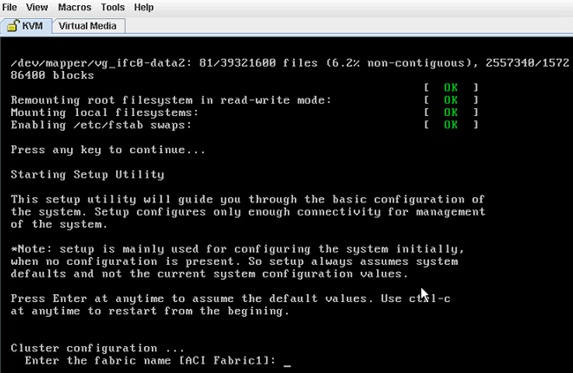
5. Press <return> to select the default value for Enter the fabric name. This value can be changed if desired.
6. Press <return> to select the default value for Enter the number of controllers in the fabric. While the fabric can operate with a single APIC, 3 APICs are recommended for redundancy.
7. Enter the controller number currently being set up under Enter the controller ID (1-3). Please remember only controller number 1 will allow you to setup the admin password. Remaining controllers and switches sync their passwords to the admin password set on the controller 1.
8. Enter the controller name or choose default name for Enter the controller name.
9. Press <return> to select the default pool under Enter the address pool for TEP addresses. If the network is already in use, please choose a different range.
10. Press <return> to select the default vlan for Enter the VLAN id for infra network.
11. Press <return> to select the default range for Enter address pool for BD multicast addresses.
12. Enter appropriate values for the out of band management network configuration. The out of band management IP address will be used to access the APIC from client browsers.
13. Enter the admin password (controller 1 only).
14. Press <return> to accept the configuration without changes.
15. Let the APIC complete its boot process.
16. Repeat the above steps for all three APIC controllers.
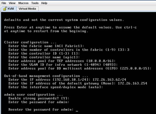
![]() Note: When APIC-1 boots up for the first time, it might take up to 5 minutes to allow login using the admin password set during the setup procedure. If something went wrong during the setup, APIC does allow login using a special user called rescue-user. If admin password was never set or was not setup properly, rescue-user will allow access to APIC without any password. If an admin password was set previously, use rescue-user with the admin password.
Note: When APIC-1 boots up for the first time, it might take up to 5 minutes to allow login using the admin password set during the setup procedure. If something went wrong during the setup, APIC does allow login using a special user called rescue-user. If admin password was never set or was not setup properly, rescue-user will allow access to APIC without any password. If an admin password was set previously, use rescue-user with the admin password.
Cisco ACI – Fabric Discovery
1. Log into the APIC GUI using a web browser*.
![]() *Note: For accessing APIC GUI, Google Chrome was utilized during validation
*Note: For accessing APIC GUI, Google Chrome was utilized during validation
2. Browse to https://<Out of Band IP address of APIC 1>.
3. Log in using admin as username and use the password defined during initial setup.
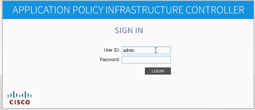
4. Click FABRIC from the top bar. Under INVENTORY, expand Fabric Membership.
5. At least one of the leaves should be visible.
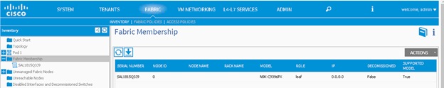
6. Click FABRIC from the top bar. Under INVENTORY, expand Fabric Membership.
7. Log into the leaf using console connection (admin/<no password needed>) and use the serial number to identify discovered leaf (Leaf-1 or Leaf-2 in the physical setup).
switch# show inventory
NAME: "Chassis", DESCR: "Nexus C9396PX Chassis"
PID: N9K-C9396PX , VID: V02 , SN: SAL1815Q3J9
<snip>
8. Double-click the identified leaf description on the right hand side and assign a NODE ID value of 101 and NODE NAME <device name>. Click UPDATE.
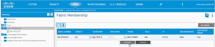
9. As the fabric discovery continues, both spines and leaves will start appearing under the Fabic Membership window. Repeat Step 7 to assign the NODE ID and NODE NAME to these devices.
10. When the NODE ID and NODE NAME values are assigned, APIC assigns IP addresses from TEP the pool defined during initial setup.
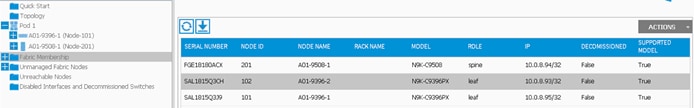
11. When both leaves and spines are added to the fabric, click Topology on the left hand side. 3 APICs, 2 leaves and 2 spines should be visible.
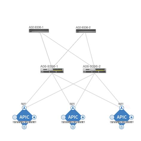
Cisco ACI – Defining Fabric Access Policies
In this section, various access policies such as CDP, LACP and LLDP etc. will be defined. These policies will be used during vPC and VM domain creation. To define fabric access policies, complete the following steps:
1. Click FABRIC and select ACCESS POLICIES under the sub-menu.
2. From the left menu bar, expand Interface Policies.
3. Expand Policies.
4. Right Click CDP Interface and select Create CDP Interface Policy.
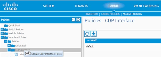
5. In the menu box, enter CDP_Enabled as the policy name and set Admin State Enabled.
6. Click SUBMIT.
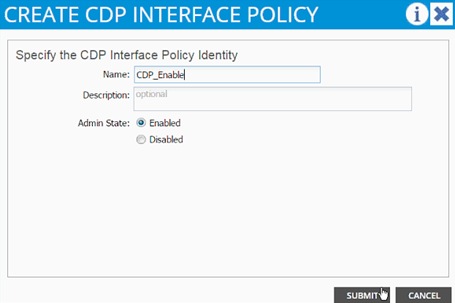
7. From the left menu bar, Expand LLDP interface.
8. Right Click and select Create LLDP Interface Policy.
9. In the menu box, enter LLDP_Disabled as the policy name and set both Transmit State and Receive State Disabled.
10. Click SUBMIT.
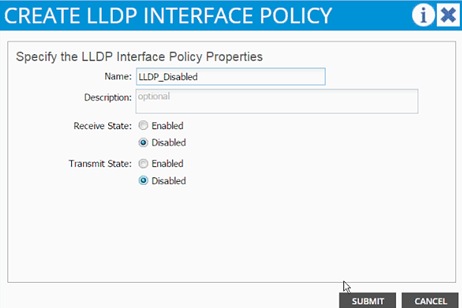
11. Right-click and select Create LLDP Interface again.
12. In the menu box, enter LLDP_Enabled as the policy name and set both Transmit State and Receive State Enabled.
13. Click SUBMIT.
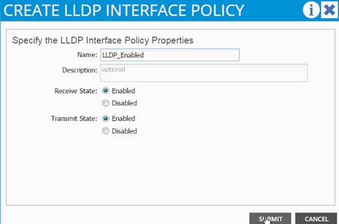
14. From the left menu bar, Expand LACP.
15. Right-click and select Create LACP Policy.
16. In the menu box, enter LACP_Active as the policy name and select Mode Active. Leave remaining options as default.
17. Click SUBMIT.
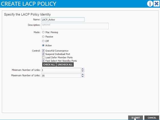
18. From the left menu bar, expand LACP.
19. Right-click and select Create LACP Policy.
20. In the menu box, enter LACP_MAC_Pinning as the policy name and select “Mode “Mac Pinning. Leave remaining options as default.
21. Click SUBMIT.
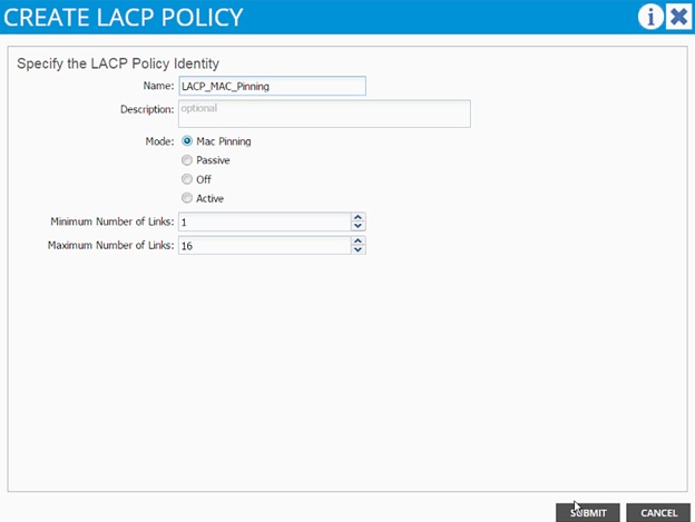
Cisco ACI – Creating vPC for Cisco UCS Fabric Interconnect A
To create a vPC for Cisco UCS Fabric Interconnect A, complete the following steps:
1. From the main menu, click FABRIC and select Access Policies.
2. Right-click Interface Policies and select Configure interface, PC and vPC.
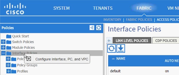
3. In the dialog box, Click + under the vPC SWITCH PAIRS.
4. Enter 10 as vPC Domain ID.
5. Drop down the Switch 1 and Switch 2 values and select both leaves.
6. Click Save.
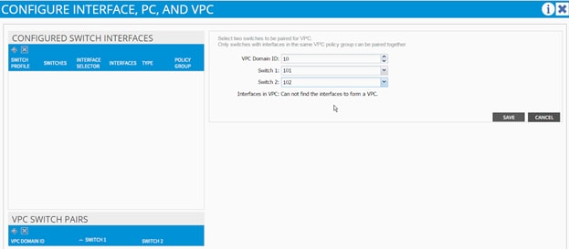
7. Validate that the create vPC domain appears under the vPC SWITCH PAIRS.
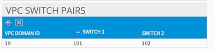
8. In the dialog box, click + under the CONFIGURED SWITCH INTERFACES.
9. Drop down the menu next to Switches and select both leaves.
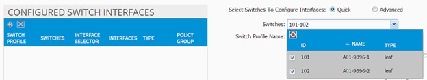
10. Enter <sp-UCS-FI-1> as Switch Profile Name. UCS-FI-1 is the host name for UCS Fabric Interconnect A.
11. Click the + sign to add interfaces.
12. Select vPC radio button to configure vPC.
13. Enter 1/19 under Interfaces. This is the port on both switches where Fabric Interconnect A is connected.
14. Enter <ifs- UCS-FI-1> as Interface Selector Name.
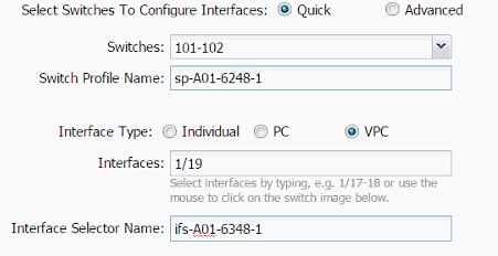
15. Drop down vPC Policy Group and click Create vPC Interface Policy Group. A new dialog box will appear.
16. Enter <pg- UCS-FI-1> as the name of the vPC INTERFACE POLICY GROUP in the dialog box.
17. Select various policy values from the drop-down menus.

18. From the Attached Entity Profile drop-down list, select Create Attachable Access Entity Profile. A new dialog box will appear.
19. The two UCS Fabric Interconnects will share this Attachable Entity Profile (AEP). Enter <aep-UCS-FI-hostname> as the Name (avoid using A or B at the end).
20. Click + to add Domain.
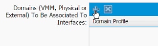
21. In the added domain, drop-down the menu and select Create Physical Domain.

22. In the Create Physical Domain dialog box, enter <pd-UCS-FI hostname> as Name.
23. Drop down the VLAN Pool menu and select Create VLAN Pool.
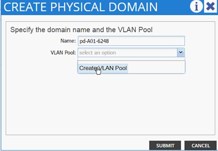
24. In the Create VLAN Pool dialog box, enter <vp-UCS-FI hostname> as Name.
25. Select Allocation Mode Static Allocation.
26. Click + next to Encap Block.
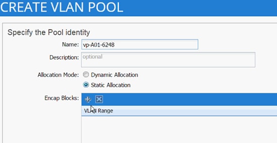
27. In the CREATE RANGES dialog box, enter the two iSCSI VLANs and the NFS VLAN.
![]() Note: In the screenshot below, 911, 912 are iSCSI VLANs and 3270 is the NFS VLAN configured on Cisco UCS.
Note: In the screenshot below, 911, 912 are iSCSI VLANs and 3270 is the NFS VLAN configured on Cisco UCS.

28. Click OK.
29. Click +again to add NFS VLAN and in the CREATE RANGES dialog box, enter range 3270-3270 (single VLAN).
30. Click OK.
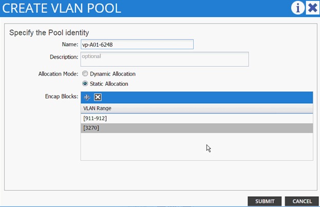
31. Click SUBMIT to finish VLAN pool creation.
32. Click SUBMIT to finish Physical Domain creation.
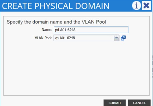
33. Click UPDATE to finish adding Physical domain to AEP.
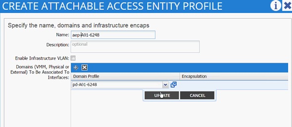
34. Click SUBMIT to finish adding AEP.
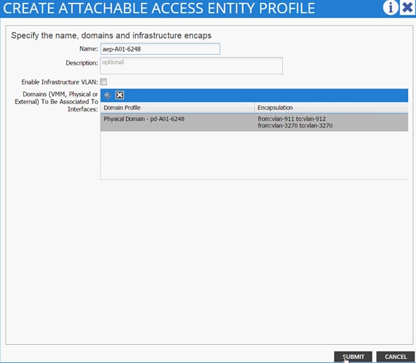
35. Click SUBMIT to finish creating vPC Interface Policy Group.
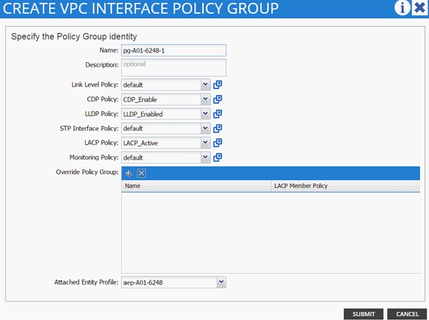
36. On the Configure Interface, PC, vPC screen, click SAVE.
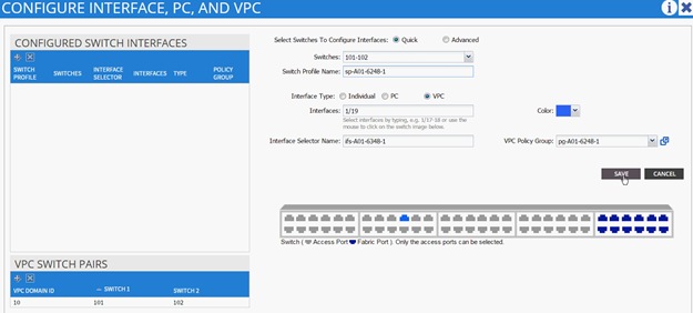
37. Click SAVE.

38. Click SUBMIT to finish the vPC creation using wizard.
39. Under Fabric, select Inventory.
40. From the left menu, expand Pod 1, expand Leaf-1 and expand Interfaces followed by vPC Interfaces.
41. Validate that the vPC domain 10 and the vPC exist.
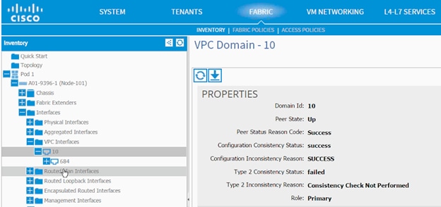
![]() Note: Log into the switch using the console and use show port-channel summary command to verify the port-channel configuration. If Cisco UCS was configured correctly, the port-channel would show UP.
Note: Log into the switch using the console and use show port-channel summary command to verify the port-channel configuration. If Cisco UCS was configured correctly, the port-channel would show UP.
Cisco ACI – Creating vPC for UCS Fabric Interconnect B
To create the vPC for Cisco UCS Fabric Interconnect B, complete the following steps:
1. From the main menu, click FABRIC and select Access Policies.
2. Right-click Interface Policies and select Configure interface, PC and vPC.
3. In the dialog box, click the + under the CONFIGURED SWITCH INTERFACES.
4. Drop down the menu next to Switches and select both leaves.

5. Enter <sp-UCS-FI-2> as Switch Profile Name. UCS-FI-2 is the host name for UCS Fabric Interconnect B.
6. Click the + sign to add interfaces.
7. Select vPC radio button to configure vPC.
8. Enter 1/20 under Interfaces. This is the port on both switches where Fabric Interconnect B is connected.
9. Enter <ifs- UCS-FI-2> as Interface Selector Name.
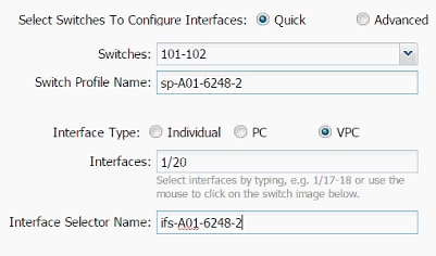
10. Drop down vPC Policy Group and click Create vPC Interface Policy Group. A new dialog box will appear.
11. Enter <pg- UCS-FI-2> as the name of the vPC INTERFACE POLICY GROUP in the dialog box.
12. Select various policy values from the drop-down menus.

13. Drop down the Attached Entity Profile and select shared AEP created in the last section.
14. Click SUBMIT to finish creating the vPC Interface Policy Group.
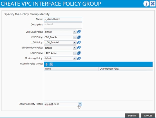
15. On the Configure Interface, PC, vPC screen, click SAVE.
16. Click SAVE.
17. Click SUBMIT to finish the vPC creation wizard.
18. (Optional) Log into the individual leaf switches and use show port-channel summary and show vpc commands to verify the configuration.
Cisco ACI – Creating vPC for NetApp Controller 1
To create the vPC for NetApp Controller 1, complete the following steps:
1. From the main menu, click FABRIC and select Access Policies.
2. Right-click Interface Policies and select Configure interface, PC and vPC.

3. In the dialog box, click + under the CONFIGURED SWITCH INTERFACES.
4. Drop down the menu next to Switches and select both leaves.
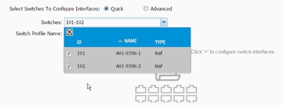
5. Enter <sp-NetAPP-1> as Switch Profile Name. NetApp-1 is the host name for NetApp Controller 1.
6. Click the + sign to add interfaces.
7. Select vPC radio button to configure vPC.
8. Enter 1/17 under Interfaces. This is the port on both switches where NetApp Controller 1 is connected.
9. Enter <ifs- NetApp-1> as Interface Selector Name.
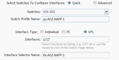
10. Drop down vPC Policy Group and click Create vPC Interface Policy Group. A new dialog box will appear.
11. Enter <pg- NetApp-1> as the name of the vPC INTERFACE POLICY GROUP in the dialog box.
12. Select various policy values from the drop-down lists.

13. Drop down the Attached Entity Profile and click Create Attachable Access Entity Profile. A new dialog box will appear.
14. The two NetApp Controllers will share the Attachable Entity Profile (AEP). Enter <aep-NetApp-hostname> as the Name. (Avoid using 1 or 2 at the end).
15. Click + to add Domain.
16. In the added domain, drop-down the menu and select Create Physical Domain.
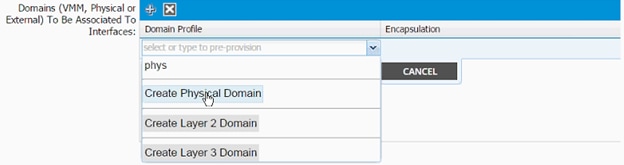
17. In the Create Physical Domain dialog box, enter <pd-NetApp-hostname> as Name.
18. Drop down the VLAN Pool menu and select Create VLAN Pool.
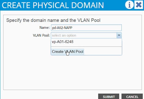
19. In the Create VLAN Pool dialog box, enter <vp-NetApp-hostname > as Name.
20. Select Allocation Mode Static Allocation.
21. Click + next to Encap Block.
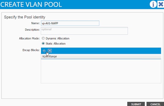
22. In the CREATE RANGES dialog box, enter the two iSCSI VLANs and the NFS VLAN.
![]() Note: In the screenshot below, 911, 912 are iSCSI VLANs and 3170 is the NFS VLAN configured on NetApp.
Note: In the screenshot below, 911, 912 are iSCSI VLANs and 3170 is the NFS VLAN configured on NetApp.
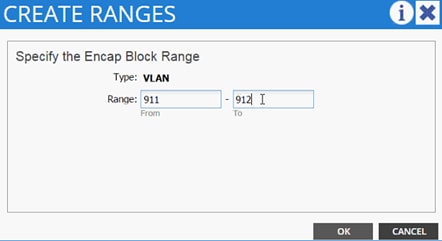
23. Click “OK.
24. Click “+ to add NFS VLAN and in the “CREATE RANGES dialog box, enter range 3170-3170 (single VLAN).
25. Click OK.
26. Click SUBMIT to finish VLAN pool creation.
27. Click SUBMIT to finish Physical Domain creation.
28. Click UPDATE to finish adding Physical domain to AEP.
29. Click SUBMIT to finish adding AEP.
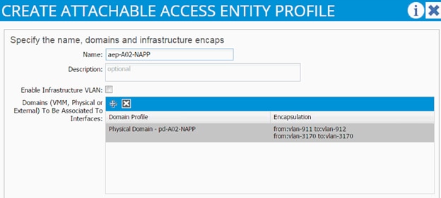
30. Click SUBMIT to finish creating vPC Interface Policy Group.
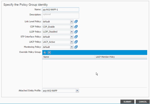
31. On the Configure Interface, PC, vPC screen, click SAVE.
32. Click SAVE.
33. Click SUBMIT to finish the vPC creation using wizard.
Cisco ACI – Creating vPC for NetApp Controller 2
To create the vPC for NetApp Controller 2, complete the following steps:
1. From the main menu, click FABRIC and select Inventory.
2. Expand Pod 1 and right click on the first leaf and select Configure interface, PC and vPC.
3. In the dialog box, click + under the CONFIGURED SWITCH INTERFACES.
4. From the Switches drop-down list, select both leaves.

5. Enter <sp-NetAPP-2> as Switch Profile Name. NetApp-2 is the host name for NetApp Controller 2.
6. Click the + sign to add interfaces.
7. Select vPC radio button to configure vPC.
8. Enter 1/18 under Interfaces. This is the port on both switches where NetApp Controller 2 is connected.
9. Enter <ifs- NetApp-2> as Interface Selector Name.
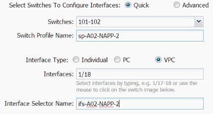
10. Drop down vPC Policy Group and click Create vPC Interface Policy Group. A new dialog box will appear.
11. Enter <pg- NetApp-2> as the name of the vPC INTERFACE POLICY GROUP in the dialog box.
12. Select various policy values from the drop-down lists.
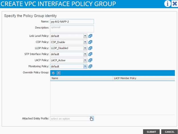
13. Drop down the Attached Entity Profile select shared AEP created in the last section.
14. Click SUBMIT to finish creating vPC Interface Policy Group.
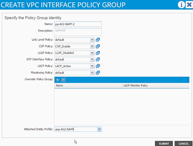
15. On the Configure Interface, PC, vPC screen, click SAVE.
16. Click SAVE.
17. Click SUBMIT to finish the vPC creation.
18. Expand the Pod 1 followed by the Leaf switch(s) on the left hand menu bar and then expand the Interfaces and vPC Interfaces.
19. Expand the vPC domain 10 and validate all the vPCs are configured and up (you will not see the VLAN being forwarded at this time).
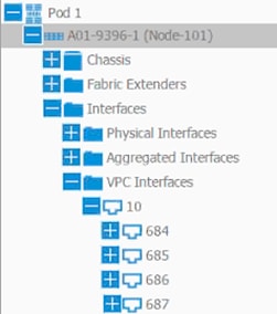
20. Optional: Log into the leaf switches using console and validate the port-channels are configured correctly. The output below assumes the NetApp and UCS port-channel configurations are in place.
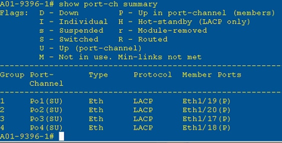
Cisco ACI – Deploying Infrastructure (Foundation) Tenant
In this section, a new tenant will be deployed to host the infrastructure connectivity between the compute (VMware) and Storage (NetApp) environments. To deploy a new tenant, complete the following steps:
1. From the main menu, click TENANTS and from the sub-menu click ADD TENANT.
2. In the CREATE TENANT dialog box, type Foundation as the name of the tenant.
3. Click the checkbox next to all under Security Domains.
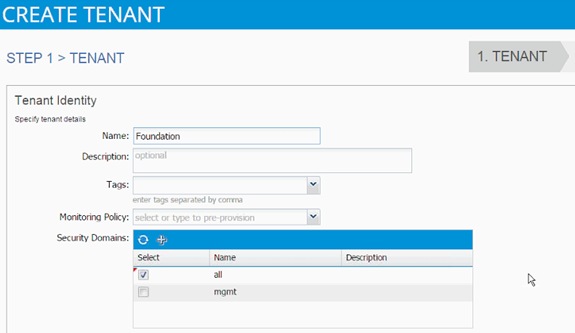
4. Click Next.
5. Click + sign to add network.
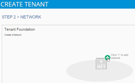
6. In the CREATE NEW NETWORK dialog box, type Foundation as the Name. Leave everything else as default.
7. Click Next to move onto bridge domain creation.
8. Use bd-Internal as the Name of the bridge domain.
9. Drop down the menu next to Forwarding and select Custom.
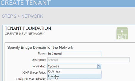
10. Check the boxes to enable Flooding and Routing.
11. Select default for IGMP Snoop Policy.
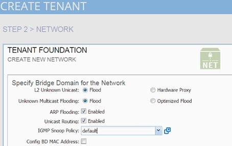
12. Click OK.
13. Click + sign next to Bridge Domain to add another Bridge Domain.
14. Add bd-iSCSI-a as the Name.
15. Select Custom > Forwarding.
16. Enable Flooding and disable Unicast routing.
17. Set IGMP Snoop Policy to default.
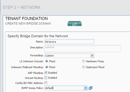
18. Click Next.
19. Click OK.
20. Click + sign next to Bridge Domain to add another Bridge Domain.
21. Add bd-iSCSI-b as the Name.
22. Select Custom Forwarding.
23. Enable Flooding and disable Unicast routing.
24. Set IGMP Snoop Policy to default.
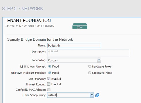
25. Click Next.
26. Click OK.
27. Three Bridge Domains and Foundation network should be visible in the CREATE TENANT dialog box.
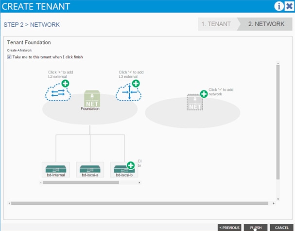
28. Click Finish.
29. Verify the selected tenant is the newly created Foundation tenant by looking at the items highlighted in the top menu.
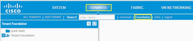
Application Profile Creation
In this section, two Application Profiles, iSCSI and NFS will be created.
iSCSI Application Profile Creation
1. Select Tenant and newly created Foundation tenant from the top menu.
2. Expand Tenant Foundation in the left menu bar.
3. Right-click Application Profile and click Create Application Profiles.
4. In the CREATE APPLICATION PROFILE dialog box, enter iSCSI as the Name.
5. From the drop-down menu, select default for Monitoring Policy.
6. Click + next to EPG to add an EPG.
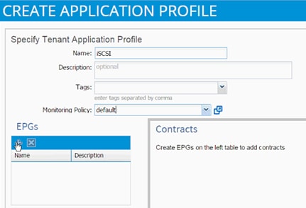
7. In the CREATE APPLICATION EPG dialog box, enter iscsi-a-lif as the Name.
8. From the drop-down menu, select bd-iscsi-a as the Bridge Domain.
9. From the drop-down menu, select default for Monitoring Policy.
10. Click FINISH.
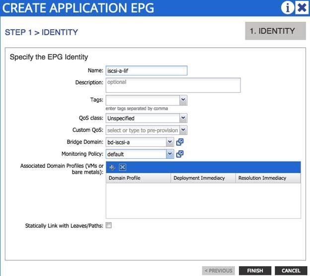
11. Click + next to EPG to add another EPG.
12. In the CREATE APPLICATION EPG dialog box, enter iscsi-b-lif as the Name.
13. From the drop-down menu, select bd-iscsi-b as the Bridge Domain.
14. From the drop-down menu, select default Monitoring Policy.
15. Click FINISH.
16. Click + next to EPG to add another EPG.
17. In the CREATE APPLICATION EPG dialog box, enter iscsi-a-vmk as the Name.
18. From the drop-down menu, select bd-iscsi-a as the Bridge Domain.
19. From the drop-down menu, select default Monitoring Policy.
20. Click FINISH.
21. Click + next to EPG to add another EPG.
22. In the CREATE APPLICATION EPG dialog box, enter iscsi-b-vmk as the Name.
23. From the drop-down menu, select bd-iscsi-b as the Bridge Domain.
24. From the drop-down menu, select default Monitoring Policy.
25. Click FINISH.
26. Click SUBMIT to finish creating the Application Profile.
Setting up EPG iscsi-a-lif
To set up the EPG iscsi-a-lif, complete the following steps:
1. Expand the newly created iSCSI Application profile from the menu bar on the left.
2. Expand iSCSI, expand Application EPGs and expand EPG iscsi-a-lif.
3. Click Static Bindings (Paths).
4. Click Action on the right hand work area.
5. Click Deploy Static EPG on PC, vPC, or Interface.
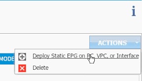
6. In the DEPLOY STATIC EPG ON PC, vPC OR INTERFACE dialog box, select Virtual Port Channel as the Path Type.
7. From the drop-down menu Path, select NetApp Controller 1.
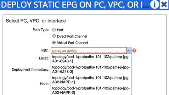
8. Enter vlan-<<var_iscsi_vlan_A_id >> for Encap (VLAN 901 is the iSCSI-A VLAN in the screen capture below).
9. Change Deployment Immediacy to Immediate.
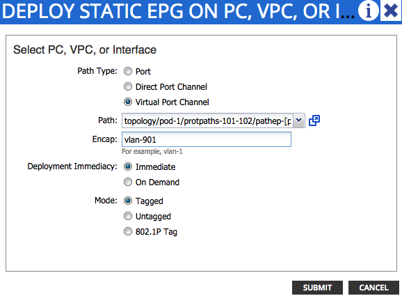
10. Click Submit.
11. Repeat steps 4-10 for mapping NetApp Controller 2 path.
12. Static bindings should display as shown below:
Figure 4 APIC - Application Profile iSCSI-A - Static Path Bindings
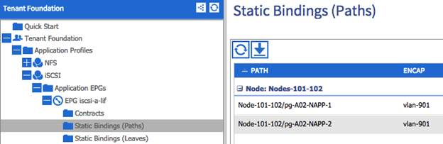
Setting up EPG iscsi-b-lif
1. Expand the iSCSI Application profile from the menu bar on the left.
2. Expand iSCSI, expand Application EPGs and expand EPG iscsi-b-lif.
3. Click Static Bindings (Paths).
4. Repeat Step 4-10 to add two static bindings for both NetApp controllers using vlan-<<var_iscsi_vlan_B_id>> as Encapsulation.
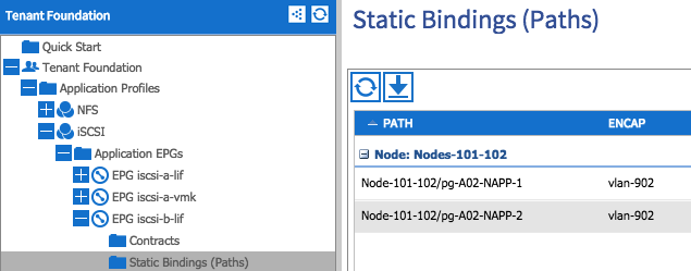
Setting up EPG iscsi-a-vmk
1. Expand the iSCSI Application profile from the menu bar on the left.
2. Expand iSCSI, expand Application EPGs and expand EPG iscsi-a-vmk.
3. Click Static Bindings (Paths).
4. Repeat Step 4 -10 to add two static bindings for both UCS Fabric Interconnects using vlan-<<var_iscsi_vlan_A_vmk>> as Encapsulation.
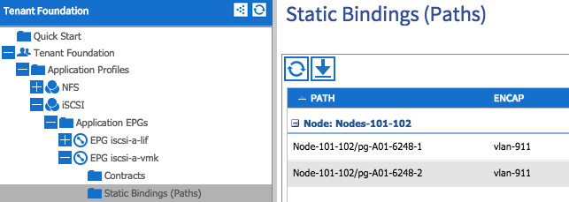
Setting up EPG iscsi-b-vmk
1. Expand the iSCSI Application profile from the menu bar on the left.
2. Expand iSCSI, expand Application EPGs and expand EPG iscsi-b-vmk.
3. Click Static Bindings (Paths).
4. Repeat Step 4-10 to add two static bindings for both UCS Fabric Interconnects using vlan-<<var_iscsi_vlan_B_vmk>> as Encapsulation.
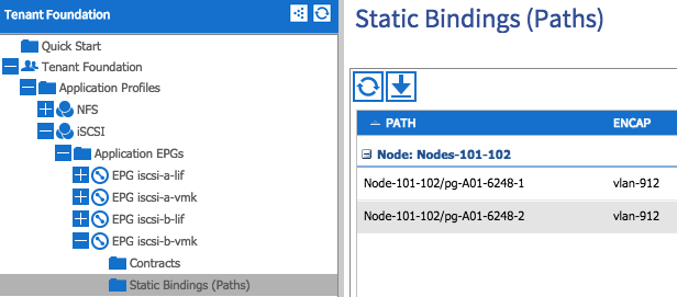
Setting up Provided Contracts
To set up the provided contracts, complete the following steps:
1. Click EPG iscsi-a-lif in the left menu.
2. Click Contracts under the EPG.
3. Click ACTIONS on the right and select Add Provided Contract.
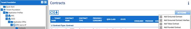
4. From the ADD PROVIDED CONTRACT dialog box, select Create Contract under Contract.

5. Enter Allow_ISCSI as Name in the CREATE CONTRACT dialog box.
6. Set Scope as Tenant.
7. Click + next to Subjects to add a new contract subject.
8. In the CREATE CONTRACT SUBJECT dialog box, enter Allow_ISCSI as the Name.
9. Click + under Filter Chain to add a new filter.
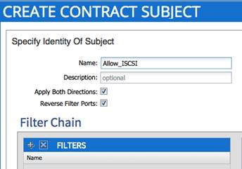
10. Drop down the menu under FILTERS and click +.
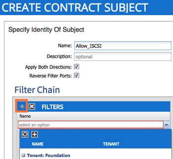
11. In the CREATE FILTER dialog box, enter Allow_ISCSI as the Name. In this example, allow all the traffic for this contract.
12. Click + to add a filter.
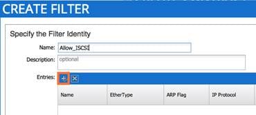
13. Enter tcp3260 as the name of the filter.
14. From drop-down menu, select IP as Ethertype.
15. From drop-down menu, select TCP as IP Protocol.
16. In Destination Port/Range type 3260 as both From and To ports.
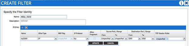
17. Click Update.
18. Click SUBMIT to create the filter.
19. Click UPDATE to add the newly created filter to the filter chain.
20. Click OK to finish creating the Contract Subject.
21. Click SUBMIT.
22. Click SUBMIT again to finish adding a provided contract.
23. Verify the Provided Contract appears under the Contracts as shown below:
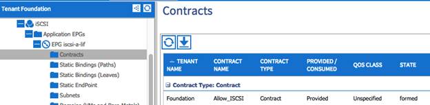
24. Click EPG iscsi-b-lif in the left menu.
25. Click Contracts under the EPG.
26. Click ACTIONS on the right and select Add Provided Contract.
27. From the drop-down menu, select the recently created Allow_ISCSI contract.
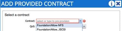
28. Click SUBMIT to add the Allow_ISCSI contract as the Provided contract for EPG iscsi-b-lif as well.
Setting up Consumes Contracts
To set up the Consumed contract, complete the following steps:
1. Click EPG iscsi-a-vmk in the left menu.
2. Click Contracts under the EPG.
3. In the ADD CONSUMED CONTRACT dialog box, from the drop-down menu select Foundation/Allow_ISCSI contract (defined in the previous step).
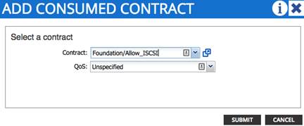
4. Click SUBMIT.
5. Click EPG iscsi-b-vmk in the left menu.
6. Click Contracts under the EPG.
7. In the ADD CONSUMED CONTRACT dialog box, from the drop-down menu select Foundation/Allow_ISCSI contract.
8. To validate the contract definition, click Application EPGs under Application Profile iSCSI in the left menu bar. The contract should appear as shown below:
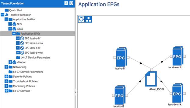
NFS Application Profile Creation
To create the NFS application profile, complete the following steps:
1. Expand Tenant Foundation in the left menu bar.
2. Right-click Application Profile and click Create Application Profile.
3. In the CREATE APPLICATION PROFILE dialog box, enter NFS as the Name.
4. From the drop-down menu, select default for Monitoring Policy.
5. Click + next to EPG to add an EPG.
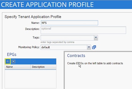
6. In the CREATE APPLICATION EPG dialog box, enter lif-nfs as the Name.
7. From the drop-down menu, select bd-internal as the Bridge Domain.
8. From the drop-down menu, select default for Monitoring Policy.
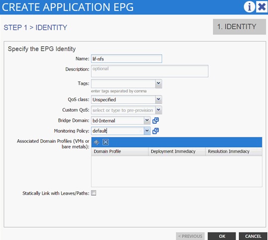
9. Click OK.
10. Click + next to EPG to another EPG.
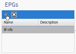
11. In the CREATE APPLICATION EPG dialog box, enter vmk-nfs as the Name.
12. From the drop-down menu, select bd-internal as the Bridge Domain.
13. From the drop-down menu, select default Monitoring Policy.
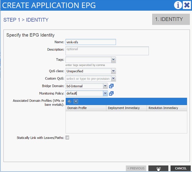
14. Click OK.
15. Click SUBMIT to finish creating the Application Profile.
16. Expand the newly created NFS Application profile from the menu bar on the left.
17. Expand NFS, expand Application EPGs and expand EPG lif-nfs.
18. Click Static Bindings (Paths).
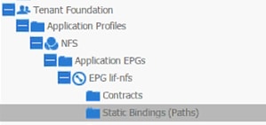
19. Click Action on the right hand work area.
20. Click Deploy Static EPG on PC, vPC, or Interface.
21. In the DEPLOY STATIC EPG ON PC, vPC OR INTERFACE dialog box, select Virtual Port Channel as the Path Type.
22. From the drop-down menu Path, select NetApp Controller 1.

23. Enter vlan-<NFS LIF VLAN> for Encap (VLAN 3170 is the NFS VLAN on NetApp Controller in the screen capture below).
24. Change Deployment Immediacy to Immediate.
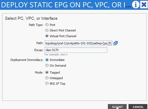
25. Click Submit.
26. Validate the path appears in the work area on the right.
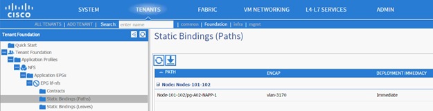
27. Repeat these steps for mapping NetApp Controller 2 path.
28. Static bindings should be similar to screenshot below:
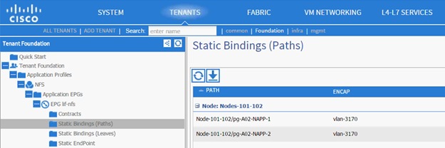
29. Click Contracts under the EPG lif-nfs.
30. Click Action and select Add Provided Contract.
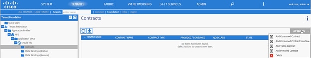
31. From the ADD PROVIDED CONTRACT dialog box, select Create Contract under Contract.
32. Enter Allow-NFS as Name in the CREATE CONTRACT dialog box.
33. Click + next to Subjects to add a new contract subject.
34. In the CREATE CONTRACT SUBJECT dialog box, enter Allow-All as the Name.
35. Click + under Filter Chain to add a new filter.
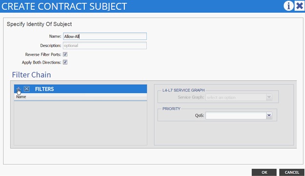
36. Drop down the menu under FILTERS and click +.

37. In the CREATE FILTER dialog box, enter Allow-All as the Name. In this example, allow all the traffic for this contract.
38. Click + to add a filter.
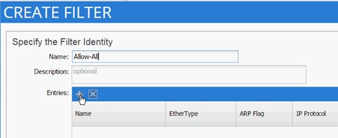
39. Enter Allow-All as the name of the filter.
40. From drop-down menu, select IP as Ethertype.
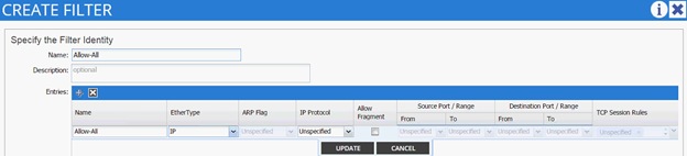
41. Click Update.
42. Click SUBMIT to create the filter.
43. Click UPDATE to add the newly created filter to the filter chain.
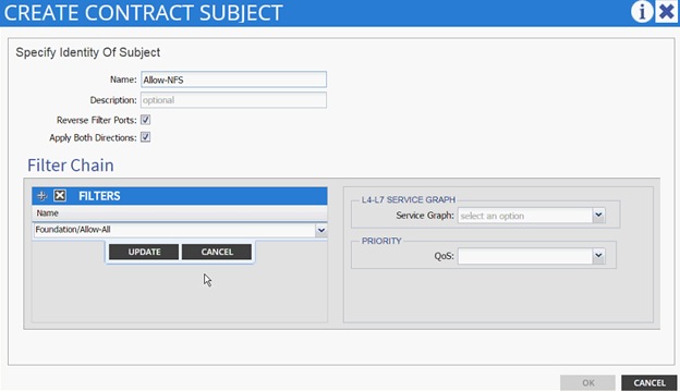
44. Click OK to finish creating the Contract Subject.
45. Change the Scope to tenant from the drop-down list.
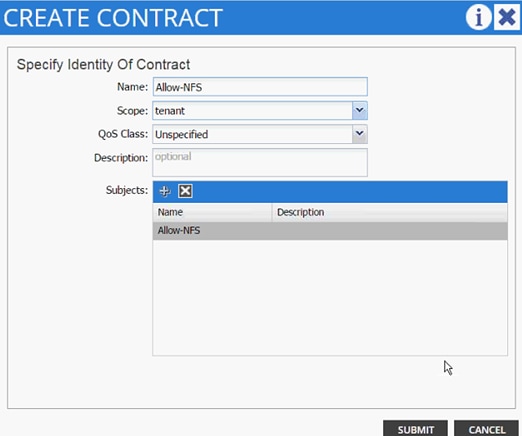
46. Click SUBMIT.
47. Click SUBMIT again to finish adding a provided contract.
48. Verify the Provided Contract appears under the Contracts.
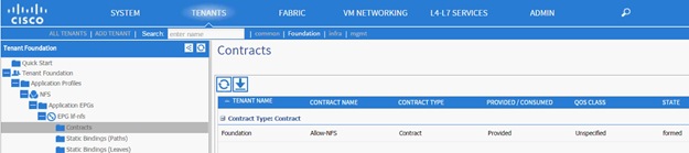
49. Expand the NFS Application profile (again) from the menu bar on the left.
50. Expand NFS, expand Application EPGs and expand EPG vmk-nfs.
51. Click Static Bindings (Paths).
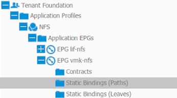
52. Click Action in the right hand work area.
53. Click Deploy Static EPG on PC, vPC, or Interface.
54. In the DEPLOY STATIC EPG ON PC, vPC OR INTERFACE dialog box, select Virtual Port Channel as the Path Type.
55. From the drop-down menu Path, select UCS Fabric Interconnect A.
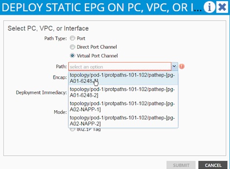
56. Enter vlan-<NFS VMK VLAN> for Encap; VLAN 3270 is the NFS VLAN on UCS Fabric Interconnect in the screenshot below.
![]() Note: A VLAN on a certain path can only be mapped to a single EPG. Since VLAN 3170 (NFS VLAN on NetApp) is already mapped to EPG lif-NFS, VLAN 3270 was selected as the VLAN to host ESXi VMKernel ports. The VMKernel ports and the NetApp LIFs will still be defined in the same IP subnet; ACI Fabric will enable seamless IP connectivity when contracts are defined between the two EPGs.
Note: A VLAN on a certain path can only be mapped to a single EPG. Since VLAN 3170 (NFS VLAN on NetApp) is already mapped to EPG lif-NFS, VLAN 3270 was selected as the VLAN to host ESXi VMKernel ports. The VMKernel ports and the NetApp LIFs will still be defined in the same IP subnet; ACI Fabric will enable seamless IP connectivity when contracts are defined between the two EPGs.
57. Change Deployment Immediacy to Immediate.
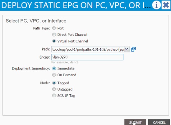
58. Click Submit.
59. Validate the path appears in the work area.

60. Repeat these steps for mapping UCS Fabric Interconnect B path.
61. Static bindings should be similar to screenshot below.
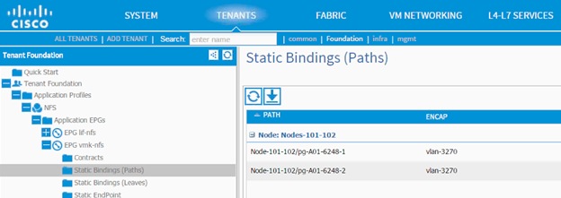
62. Click Contracts in the left menu.
63. Click ACTIONS on the right and select Add Consumed Contract.
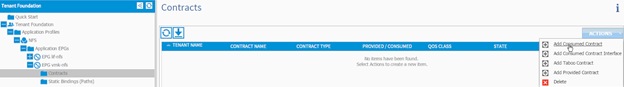
64. In the ADD CONSUMED CONTRACT dialog box, from the drop-down menu select Foundation/Allow-NFS contract (defined previously).
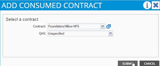
65. Click SUBMIT.
66. To validate the contract definition, click Application EPGs under Application Profile NFS in the left menu bar. The contract should appear as shown in screenshot below:
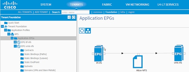
Path (vPC) Validation
Previously in this section, both iSCSI and NFS paths and VLANs were mapped to appropriate EPGs. These VLANs were also defined in the physical domains associated with the VPCs. At this point the Foundation tenant is deployed and should provide connectivity between the ESXi hosts and NetApp controllers. To validate connectivity, VPCs can be checked for appropriate VLAN forwarding.
To validate the path, complete the following steps:
67. To validate the VLAN forwarding on the vPC, select FABRIC from the top menu and select INVENTORY from the sub-menu.
68. Expand Pod 1, Leaf switch, Interfaces and then vPC Interfaces.
69. Expand the vPC domain (10) and click on a vPC.
70. As shown in the screenshot below, the vPC should show both the iSCSI and NFS VLANs being forwarded.
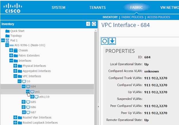
71. Repeat these steps to validate all the VPCs.
72. Optional: Log into the Leaf using CLI and issue a show vpc command.
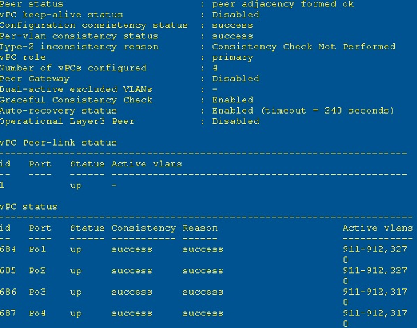
Clustered Data ONTAP SAN Boot Storage Setup
Create igroups
1. From the cluster management node SSH connection, enter the following:
igroup create –vserver Infra-SVM –igroup VM-Host-Infra-01 –protocol iscsi –ostype vmware –initiator <<var_vm_host_infra_01_iqn>>
igroup create –vserver Infra-SVM –igroup VM-Host-Infra-02 –protocol iscsi –ostype vmware –initiator <<var_vm_host_infra_02_iqn>>
igroup create –vserver Infra-SVM –igroup MGMT-Hosts –protocol iscsi –ostype vmware –initiator <<var_vm_host_infra_01_iqn>>, <<var_vm_host_infra_02_iqn>>
![]() Note: Use the values listed in Table 19 for the IQN information.
Note: Use the values listed in Table 19 for the IQN information.
![]() Note: To view the three igroups just created, type igroup show.
Note: To view the three igroups just created, type igroup show.
Map Boot LUNs to igroups
1. From the storage cluster management SSH connection, enter the following:
lun map –vserver Infra-SVM –volume esxi_boot –lun VM-Host-Infra-01 –igroup VM-Host-Infra-01 –lun-id 0
lun map –vserver Infra-SVM –volume esxi_boot –lun VM-Host-Infra-02 –igroup VM-Host-Infra-02 –lun-id 0
VMware ESXi 5.5 Update 2
This section provides detailed instructions for installing VMware ESXi 5.5 Update 2 in an environment. After the procedures are completed, two booted ESXi hosts will be provisioned.
Several methods exist for installing ESXi in a VMware environment. These procedures focus on how to use the built-in keyboard, video, mouse (KVM) console and virtual media features in Cisco UCS Manager to map remote installation media to individual servers and connect to their boot logical unit numbers (LUNs).
Download Cisco Custom Image for ESXi 5.5.0 U2
1. Click the following link vmware login page.
2. Type your email or customer number and the password and then click Log in.
3. Click the following link CiscoCustomImage5.5.0U2.
4. Click Download Now.
5. Save it to your destination folder.
![]() Note: This ESXi 5.5.0 U2 Cisco custom image includes updates for the fnic and enic drivers. The versions that are part of this image are: Enic: 2.1.2.59; Fnic: 1.6.0.12
Note: This ESXi 5.5.0 U2 Cisco custom image includes updates for the fnic and enic drivers. The versions that are part of this image are: Enic: 2.1.2.59; Fnic: 1.6.0.12
Log in to Cisco UCS 6200 Fabric Interconnect
Cisco UCS Manager
The IP KVM enables the administrator to begin the installation of the operating system (OS) through remote media. It is necessary to log in to the Cisco UCS environment to run the IP KVM.
To log in to the Cisco UCS environment, complete the following steps:
1. Open a web browser and enter the IP address for the Cisco UCS cluster address. This step launches the Cisco UCS Manager application.
2. To download the Cisco UCS Manager software, click the Launch UCS Manager link.
3. If prompted to accept security certificates, accept as necessary.
4. When prompted, enter admin as the user name and enter the administrative password.
5. To log in to Cisco UCS Manager, click Login.
6. From the main menu, click the Servers tab.
7. Select Servers > Service Profiles > root > VM-Host-Infra-01.
8. Right-click VM-Host-Infra-01 and select KVM Console.
9. If prompted to accept an Unencrypted KVM session, accept as necessary.
10. Select Servers > Service Profiles > root > VM-Host-Infra-02.
11. Right-click VM-Host-Infra-02 and select KVM Console.
12. If prompted to accept an Unencrypted KVM session, accept as necessary.
Set Up VMware ESXi Installation
ESXi Hosts VM-Host-Infra-01 and VM-Host-Infra-02
To prepare the server for the OS installation, complete the following steps on each ESXi host:
1. In the KVM window, click Virtual Media.
2. Click Activate Virtual Devices
3. If prompted to accept an Unencrypted KVM session, accept as necessary.
4. Click Virtual Media and select Map CD/DVD.
5. Browse to the ESXi installer ISO image file and click Open.
6. Click Map Device.
7. Click the KVM tab to monitor the server boot.
8. Boot the server by selecting Boot Server and clicking OK. Click OK again.
Install ESXi
ESXi Hosts VM-Host-Infra-01 and VM-Host-Infra-02
To install VMware ESXi to the SAN-bootable LUN of the hosts, complete the following steps on each host:
1. On reboot, the machine detects the presence of the ESXi installation media. Select the ESXi installer from the boot menu that is displayed.
2. After the installer is finished loading, press Enter to continue with the installation.
3. Read and accept the end-user license agreement (EULA). Press F11 to accept and continue.
4. Select the LUN that was previously set up as the installation disk for ESXi and press Enter to continue with the installation.
5. Select the appropriate keyboard layout and press Enter.
6. Enter and confirm the root password and press Enter.
7. The installer issues a warning that the selected disk will be repartitioned. Press F11 to continue with the installation.
8. After the installation is complete, click on the Virtual Media tab and clear the P mark next to the ESXi installation media. Click Yes.
![]() Note: The ESXi installation image must be unmapped to make sure that the server reboots into ESXi and not into the installer.
Note: The ESXi installation image must be unmapped to make sure that the server reboots into ESXi and not into the installer.
9. From the KVM tab, press Enter to reboot the server.
Set Up Management Networking for ESXi Hosts
Adding a management network for each VMware host is necessary for managing the host. To add a management network for the VMware hosts, complete the following steps on each ESXi host:
ESXi Host VM-Host-Infra-01
To configure the VM-Host-Infra-01 ESXi host with access to the management network, complete the following steps:
1. After the server has finished rebooting, press F2 to customize the system.
2. Log in as root, enter the corresponding password, and press Enter to log in.
3. Select the Configure the Management Network option and press Enter.
4. Select the VLAN (Optional) option and press Enter.
5. Enter the <<var_ib_mgmt_vlan_id>> and press Enter.
6. Select Network Adapters option and select vmnic4 (defined earlier as OOB vNIC) and press Enter.
7. From the Configure Management Network menu, select IP Configuration and press Enter.
8. Select the Set Static IP Address and Network Configuration option by using the space bar.
9. Enter the IP address for managing the first ESXi host: <<var_vm_host_infra_01_ip>>.
10. Enter the subnet mask for the first ESXi host.
11. Enter the default gateway for the first ESXi host.
12. Press Enter to accept the changes to the IP configuration.
13. Select the IPv6 Configuration option and press Enter.
14. Using the spacebar, unselect Enable IPv6 (restart required) and press Enter.
15. Select the DNS Configuration option and press Enter.
![]() Note: Because the IP address is assigned manually, the DNS information must also be entered manually.
Note: Because the IP address is assigned manually, the DNS information must also be entered manually.
16. Enter the IP address of the primary DNS server.
17. Optional: Enter the IP address of the secondary DNS server.
18. Enter the fully qualified domain name (FQDN) for the first ESXi host.
19. Press Enter to accept the changes to the DNS configuration.
20. Press Esc to exit the Configure Management Network submenu.
21. Press Y to confirm the changes and return to the main menu.
22. The ESXi host reboots. After reboot, press F2 and log back in as root.
23. Select Test Management Network to verify that the management network is set up correctly and press Enter.
24. Press Enter to run the test.
25. Press Enter to exit the window.
26. Press Esc to log out of the VMware console.
ESXi Host VM-Host-Infra-02
To configure the VM-Host-Infra-02 ESXi host with access to the management network, complete the following steps:
1. After the server has finished rebooting, press F2 to customize the system.
2. Log in as root and enter the corresponding password.
3. Select the Configure the Management Network option and press Enter.
4. Select the VLAN (Optional) option and press Enter.
5. Enter the <<var_ib-mgmt_vlan_id>> and press Enter.
6. Select Network Adapters option and select vmnic4 (defined earlier as OOB vNIC) and press Enter.
7. From the Configure Management Network menu, select IP Configuration and press Enter.
8. Select the Set Static IP Address and Network Configuration option by using the space bar.
9. Enter the IP address for managing the second ESXi host: <<var_vm_host_infra_02_ip>>.
10. Enter the subnet mask for the second ESXi host.
11. Enter the default gateway for the second ESXi host.
12. Press Enter to accept the changes to the IP configuration.
13. Select the IPv6 Configuration option and press Enter.
14. Using the spacebar, clear Enable IPv6 (restart required) and press Enter.
15. Select the DNS Configuration option and press Enter.
![]() Note: Because the IP address is assigned manually, the DNS information must also be entered manually.
Note: Because the IP address is assigned manually, the DNS information must also be entered manually.
16. Enter the IP address of the primary DNS server.
17. Optional: Enter the IP address of the secondary DNS server.
18. Enter the FQDN for the second ESXi host.
19. Press Enter to accept the changes to the DNS configuration.
20. Press Esc to exit the Configure Management Network submenu.
21. Press Y to confirm the changes and return to the main menu.
22. The ESXi host reboots. After reboot, press F2 and log back in as root.
23. Select Test Management Network to verify that the management network is set up correctly and press Enter.
24. Press Enter to run the test.
25. Press Enter to exit the window.
26. Press Esc to log out of the VMware console.
Download VMware vSphere Client
To download the VMware vSphere Client, complete the following steps:
1. Open a web browser on the management workstation and navigate to the VM-Host-Infra-01 management IP address.
2. Download and install the vSphere Client.
![]() Note: This application is downloaded from the VMware website and Internet access is required on the management workstation.
Note: This application is downloaded from the VMware website and Internet access is required on the management workstation.
Download VMware vSphere CLI 5.5
1. Click the following link VMware vSphere CLI 5.5
2. Select your OS and click Download.
3. Save it to destination folder.
4. Run the VMware-vSphere-CLI-5.5.0.exe.
5. Click Next.
6. Accept the terms for the license and click Next.
7. Click Next on the Destination Folder screen.
8. Click Install.
9. Click Finish.
![]() Note: Install VMware vSphere CLI 5.5 on the management workstation.
Note: Install VMware vSphere CLI 5.5 on the management workstation.
Log in to VMware ESXi Hosts by Using VMware vSphere Client
ESXi Host VM-Host-Infra-01
To log in to the VM-Host-Infra-01 ESXi host by using the VMware vSphere Client, complete the following steps:
1. Open the recently downloaded VMware vSphere Client and enter the IP address of VM-Host-Infra-01 as the host you are trying to connect to: <<var_vm_host_infra_01_ip>>.
2. Enter root for the user name.
3. Enter the root password.
4. Click Login to connect.
ESXi Host VM-Host-Infra-02
To log in to the VM-Host-Infra-02 ESXi host by using the VMware vSphere Client, complete the following steps:
1. Open the recently downloaded VMware vSphere Client and enter the IP address of VM-Host-Infra-02 as the host you are trying to connect to: <<var_vm_host_infra_02_ip>>.
2. Enter root for the user name.
3. Enter the root password.
Set Up VMkernel Ports and Virtual Switch
ESXi Host VM-Host-Infra-01
To set up the VMkernel ports and the virtual switches on the VM-Host-Infra-01. ESXi host, complete the following steps:
1. From the vSphere Client, select the host in the inventory.
2. Click the Configuration tab.
3. In the Hardware pane, click Networking.
4. On the right side of vSwitch0, click Properties.
5. Select the vSwitch configuration and click Edit.
6. From the General tab, change the MTU to 9000.
7. Click OK.
8. Click Network Adapters tab, click Add.
9. Select vmnic5 and click Next.
10. Click Next and then click Finish.
11. Click the Ports tab.
12. Select the Management Network configuration and click Edit.
13. Change the network label to <VMkernel-MGMT> and select the Management Traffic checkbox.
14. Click OK to finalize the edits for Management Network.
15. Select the VM Network configuration and click Edit.
16. Change the network label to <MGMT Network> and enter <<var_ib-mgmt_vlan_id>> in the VLAN ID (Optional) field.
17. Click OK to finalize the edits for VM Network.
18. Click Close.
19. On the right side of iScsiBootvSwitch, click Properties.
20. Select the vSwitch configuration and click Edit
21. Change the MTU to 9000.
22. Click OK.
23. Select iScsiBootPG and click Edit.
24. Change the Network Label to <VMkernel-iSCSI-A>.
25. Change the MTU to 9000.
26. Click OK.
27. Click Close.
28. In the vSphere Standard Switch view, click Add Networking.
29. Select VMkernel and click Next.
30. Select Create a vSphere standard switch to create a new vSphere standard switch.
31. Select the check boxes for the network adapter vmnic3.
32. Click Next.
33. Change the network label to <VMkernel-iSCSI-B>.
34. Click Next.
35. Enter the IP address and the subnet mask for the iSCSI VLAN B interface for VM-Host-Infra-01.
![]() Note: To obtain the iSCSI IP address information; login to the Cisco UCS Manager and in the servers tab select the corresponding service profiles. In the right pane, click the boot order and select the iSCSI-B-vNIC; click set iSCSI boot parameters; the IP address should appear as the initiator IP address.
Note: To obtain the iSCSI IP address information; login to the Cisco UCS Manager and in the servers tab select the corresponding service profiles. In the right pane, click the boot order and select the iSCSI-B-vNIC; click set iSCSI boot parameters; the IP address should appear as the initiator IP address.
36. Click Next.
37. Click Finish.
38. On the right side of vSwitch1, click Properties.
39. Select the vSwitch configuration and click Edit.
40. Change the MTU to 9000.
41. Click OK
42. Select VMkernel-iSCSI-B and click Edit.
43. Change the MTU to 9000.
44. Click OK.
45. Click Close.
46. In the vSphere Standard Switch view, click Add Networking.
47. Select VMkernel and click Next.
48. Select Create a vSphere standard switch to create a new vSphere standard switch.
49. Select vmnic6 and vmnic7 and click Next.
50. Change the network label to <VMkernel-NFS> and enter <var_nfs_vlan_id> in the VLAN ID (Optional) field.
51. Click Next.
52. Enter the IP address <<var_nfs_vlan_ip_host_01>> and the subnet mask <<var_nfs_vlan_ip_mask_host_01>> for the NFS VLAN interface for VM-Host-Infra-01.
53. To continue with the NFS VMkernel creation, click Next.
54. To finalize the creation of the NFS VMkernel interface, click Finish.
55. Select the <vSwitch> configuration and click Edit.
56. Change the MTU to 9000.
57. Click OK.
58. Select the <VMkernel-NFS> configuration and click Edit.
59. Change the MTU to 9000.
60. Click OK to finalize the edits for the VMkernel-NFS network. The properties vSwitch2 should be similar to the following example:
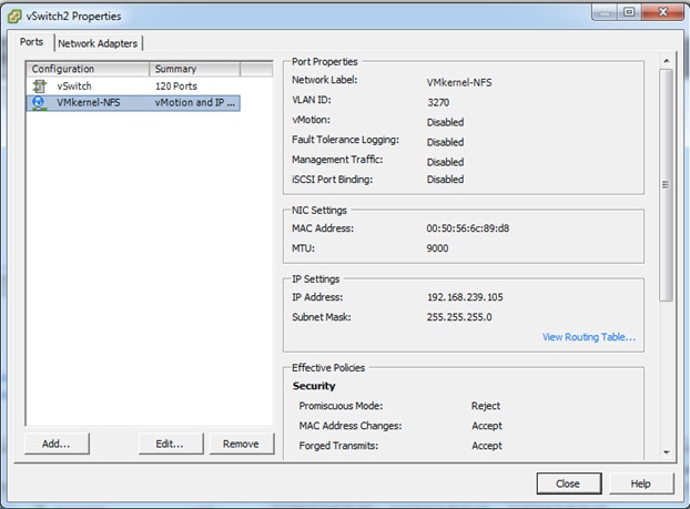
61. To finalize the ESXi host networking setup, close the dialog box. The networking for the ESXi host should be similar to the following example:
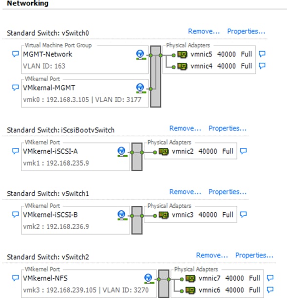
ESXi Host VM-Host-Infra-02
To set up the VMkernel ports and the virtual switches on the VM-Host-Infra-02. ESXi host, complete the following steps:
1. From the vSphere Client, select the host in the inventory.
2. Click the Configuration tab.
3. In the Hardware pane, click Networking.
4. On the right side of vSwitch0, click Properties.
5. Select the vSwitch configuration and click Edit.
6. From the General tab, change the MTU to 9000.
7. Click OK.
8. Click Network Adapters tab, click Add.
9. Select vmnic5 and click Next.
10. Click Next and then click Finish.
11. Click the Ports tab.
12. Select the Management Network configuration and click Edit.
13. Change the network label to <VMkernel-MGMT> and select the Management Traffic checkbox.
14. Click OK to finalize the edits for Management Network.
15. Select the VM Network configuration and click Edit.
16. Change the network label to <MGMT Network> and enter <<var_ib-mgmt_vlan_id>> in the VLAN ID (Optional) field.
17. Click OK to finalize the edits for VM Network.
18. Click Close.
19. On the right side of iScsiBootvSwitch, click Properties.
20. Select the vSwitch configuration and click Edit.
21. Change the MTU to 9000.
22. Click OK.
23. Select iScsiBootPG and click Edit.
24. Change the Network Label to <VMkernel-iSCSI-A>.
25. Change the MTU to 9000.
26. Click OK.
27. Click Close.
28. In the vSphere Standard Switch view, click Add Networking.
29. Select VMkernel and click Next.
30. Select Create a vSphere standard switch to create a new vSphere standard switch.
31. Select the check boxes for the network adapter vmnic3.
32. Click Next.
33. Change the network label to <VMkernel-iSCSI-B>.
34. Click Next.
35. Enter the IP address and the subnet mask for the iSCSI VLAN interface for VM-Host-Infra-02.
36. Click Next.
37. Click Finish.
38. On the right side of vSwitch1, click Properties.
39. Select the vSwitch configuration and click Edit.
40. Change the MTU to 9000.
41. Click OK.
42. Select VMkernel-iSCSI-B and click Edit.
43. Change the MTU to 9000.
44. Click OK.
45. Click Close.
46. In the vSphere Standard Switch view, click Add Networking.
47. Select VMkernel and click Next.
48. Select Create a vSphere standard switch to create a new vSphere standard switch.
49. Select vmnic6 and vmnic7 and click Next.
50. Change the network label to <VMkernel-NFS> and enter <<var_nfs_vlan_id>> in the VLAN ID (Optional) field.
51. Click Next.
52. Enter the IP address <<var_nfs_vlan_ip_host_02>> and the subnet mask <<var_nfs_vlan_ip_mask_host_02>> for the NFS VLAN interface for VM-Host-Infra-02.
53. To continue with the NFS VMkernel creation, click Next.
54. To finalize the creation of the NFS VMkernel interface, click Finish.
55. Select the <<vSwitch>> configuration and click Edit.
56. Change the MTU to 9000.
57. Click OK.
58. Select the <<VMkernel-NFS>> configuration and click Edit.
59. Change the MTU to 9000.
60. Click OK to finalize the edits for the VMkernel-NFS network. The properties vSwitch2 should be similar to the following example:
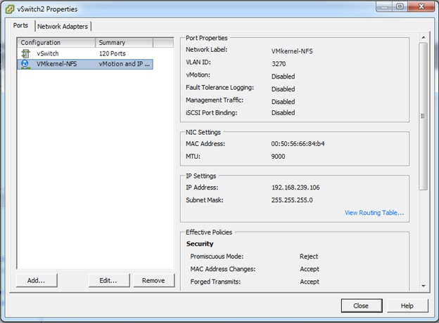
61. To finalize the ESXi host networking setup, close the dialog box. The networking for the ESXi host should be similar to the following example:
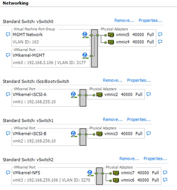
Setup iSCSI Multipathing
ESXi Hosts VM-Host-Infra-01 and VM-Host-Infra-02
To setup 4 iSCSI paths between storage and the ESXi host, complete the following steps on each ESXi host:
1. From the vSphere Client, click Storage Adapters in the Hardware pane.
2. Select the iSCSI Software Adapter and click Properties.
3. Select the Dynamic Discovery tab and click Add.
4. Enter the IP address of iscsi_lif01a.
5. Click OK.
6. Repeat putting in the IP addresses of iscsi_lif01b, iscsi_lif02a and iscsi_lif02b.
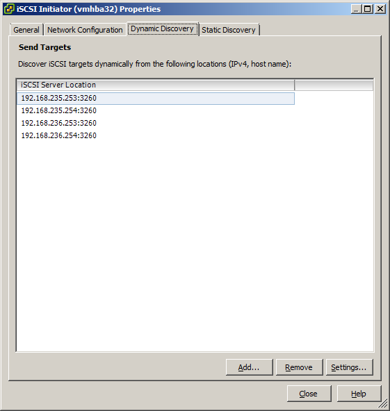
7. Click Close and then click yes to rescan the host bus adapter.
8. You should now see 4 connected paths in the Details pane.
Install VMware Drivers for the Cisco Virtual Interface Card (VIC)
Download and extract the following VMware VIC Drivers to the Management workstation:
![]() Note: Click this link for driver download instructions: http://www.cisco.com/c/en/us/td/docs/unified_computing/ucs/sw/vic_drivers/install/ESX/2-0/b_Cisco_VIC_Drivers_for_ESX_Installation_Guide/Cisco_VIC_Drivers_for_ESX_Installation_Guide_chapter2.html.
Note: Click this link for driver download instructions: http://www.cisco.com/c/en/us/td/docs/unified_computing/ucs/sw/vic_drivers/install/ESX/2-0/b_Cisco_VIC_Drivers_for_ESX_Installation_Guide/Cisco_VIC_Drivers_for_ESX_Installation_Guide_chapter2.html.
ESXi Hosts VM-Host-Infra-01 and VM-Host-Infra-02
To install VMware VIC Drivers on the ESXi host VM-Host-Infra-01 and VM-Host-Infra-02, complete the following steps:
1. From each vSphere Client, select the host in the inventory.
2. Click the Summary tab to view the environment summary.
3. From Resources > Storage, right-click datastore1 and select Browse Datastore.
4. Click the fourth button and select Upload File.
5. Navigate to the saved location for the downloaded VIC drivers and select fnic_driver_1.6.0.12b-offline_bundle-2340688.zip.
6. Click Open and Yes to upload the file to datastore1.
7. Click the fourth button and select Upload File.
8. Navigate to the saved location for the downloaded VIC drivers and select enic-2.1.2.62-esx55-offline_bundle-2340678.zip.
9. Click Open and Yes to upload the file to datastore1.
10. Make sure the files have been uploaded to both ESXi hosts.
11. From the management workstation, open the VMware vSphere Remote CLI that was previously installed.
12. At the command prompt, run the following commands to account for each host
esxcli –s <<var_vm_host_infra_01_ip>> -u root –p <<var_password>> software vib update -d /vmfs/volumes/datastore1/ fnic_driver_1.6.0.12b-offline_bundle-2340688.zip
esxcli –s <<var_vm_host_infra_02_ip>> -u root –p <<var_password>> software vib update -d /vmfs/volumes/datastore1/ fnic_driver_1.6.0.12b-offline_bundle-2340688.zip
esxcli –s <<var_vm_host_infra_01_ip>> -u root –p <<var_password>> software vib update -d /vmfs/volumes/datastore1/ enic-2.1.2.62-esx55-offline_bundle-2340678.zip
esxcli –s <<var_vm_host_infra_02_ip>> -u root –p <<var_password>> software vib update -d /vmfs/volumes/datastore1/ enic-2.1.2.62-esx55-offline_bundle-2340678.zip
13. Back in the vSphere Client for each host, right-click the host and select Reboot.
14. Click Yes and OK to reboot the host.
15. Log back into each host with vSphere Client.
Mount Required Datastores
ESXi Hosts VM-Host-Infra-01 and VM-Host-Infra-02
To mount the required datastores, complete the following steps on each ESXi host:
1. From the vSphere Client, select the host in the inventory.
2. To enable configurations, click the Configuration tab.
3. Click Storage in the Hardware pane.
4. From the Datastores area, click Add Storage to open the Add Storage wizard.
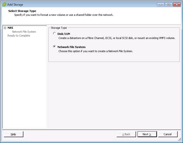
5. Select Network File System and click Next.
6. The wizard prompts for the location of the NFS export. Enter <<var_node02_nfs_lif_infra_datastore_1_ip>> as the IP address for nfs_lif_infra_datastore_1.
7. Enter /infra_datastore_1 as the path for the NFS export.
8. Confirm that the Mount NFS read only checkbox is not selected.
9. Enter infra_datastore_1 as the datastore name.
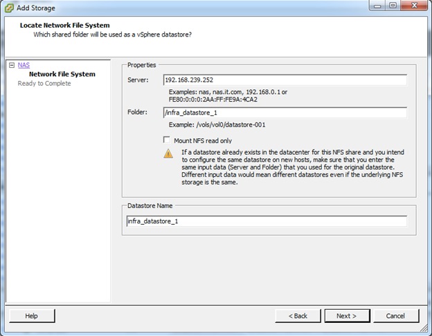
10. To continue with the NFS datastore creation, click Next.
11. To finalize the creation of the NFS datastore, click Finish.
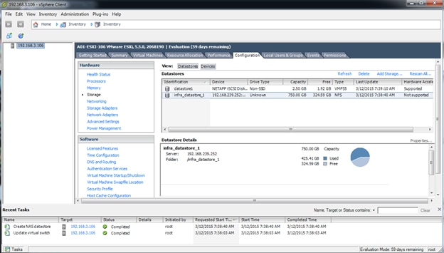
12. From the Datastores area, click Add Storage to open the Add Storage wizard.
13. Select Network File System and click Next.
14. The wizard prompts for the location of the NFS export. Enter <<var_node01_nfs_lif_infra_swap_ip>> as the IP address for nfs_lif_infra_swap.
15. Enter /infra_swap as the path for the NFS export.
16. Confirm that the Mount NFS read only checkbox is not selected.
17. Enter infra_swap as the datastore name.
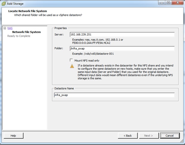
18. To continue with the NFS datastore creation, click Next.
19. To finalize the creation of the NFS datastore, click Finish.
Configure NTP on ESXi Hosts
ESXi Hosts VM-Host-Infra-01 and VM-Host-Infra-02
To configure Network Time Protocol (NTP) on the ESXi hosts, complete the following steps on each host:
1. From the vSphere Client, select the host in the inventory.
2. To enable configurations, click the Configuration tab.
3. Click Time Configuration in the Software pane.
4. Click Properties at the upper-right side of the window.
5. At the bottom of the Time Configuration dialog box, click Options.
6. In the NTP Daemon (ntpd) Options dialog box, complete the following steps:
a. Click General in the left pane and select Start and stop with host.
b. Click NTP Settings in the left pane and click Add.
7. In the Add NTP Server dialog box, enter <<var_global_ntp_server_ip>> as the IP address of the NTP server and click OK.
8. In the NTP Daemon Options dialog box, select the Restart NTP service to apply changes checkbox and click OK.
9. In the Time Configuration dialog box, complete the following steps:
a. Select the NTP Client Enabled checkbox and click OK.
b. Verify that the clock is now set to approximately the correct time.
![]() Note: The NTP server time may vary slightly from the host time.
Note: The NTP server time may vary slightly from the host time.
Move VM Swap File Location
ESXi VM-Host-Infra-01 and VM-Host-Infra-02
To move the VM swap file location, complete the following steps on each ESXi host:
1. From the vSphere Client, select the host in the inventory.
2. To enable configurations, click the Configuration tab.
3. Click Virtual Machine Swapfile Location in the Software pane.
4. Click Edit at the upper-right side of the window.
5. Select Store the swapfile in a swapfile datastore selected below.
6. Select the <datastore_name> datastore in which to house the swap files.
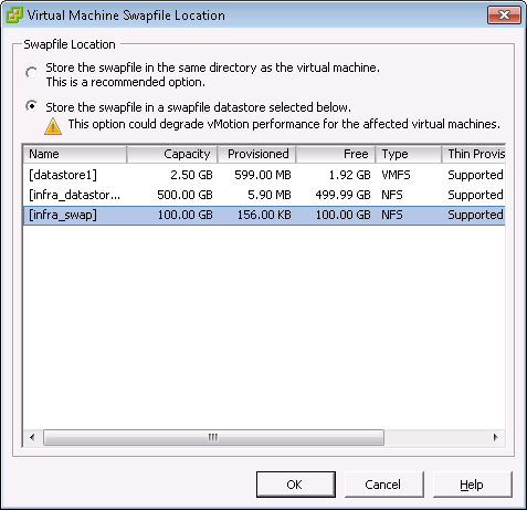
7. Click OK to finalize moving the swap file location.
VMware vCenter 5.5 Update 2
The procedures in the following subsections provide detailed instructions for installing VMware vCenter 5.5 Update 1 in an environment. After the procedures are completed, a VMware vCenter Server will be configured.
Build Microsoft SQL Server VM
To build a SQL Server Virtual Machine (VM) for the VM-Host-Infra-01, complete the following steps:
1. Log in to the host by using the VMware vSphere Client.
2. In the vSphere Client, choose the host in the inventory pane.
3. Right-click the host and choose New Virtual Machine.
4. Choose Custom and click Next.
5. Enter a name for the VM. Click Next.
6. Choose <<datastore_name>>. Click Next.
7. Choose Virtual Machine Version: 8. Click Next.
8. Verify that the Windows option and the Microsoft Windows Server 2012 (64 Bit) version are selected. Click Next.
9. Choose two virtual sockets and one core per virtual socket. Click Next.
10. Choose 8GB of memory. Click Next.
11. Choose one network interface card (NIC).
12. For NIC 1, choose the <<Network>> Network option and the VMXNET 3 adapter. Click Next.
13. Keep the LSI Logic SAS option for the SCSI controller Selected. Click Next.
14. Keep the Create a New Virtual Disk Option selected. Click Next.
15. Make the disk size at least 80GB. Click Next.
16. Click Next.
17. Check the edit the virtual machine setting before completion. Click Continue.
18. Click the Options tab.
19. Choose Boot Options.
20. Check the Force Bios Setup check box.
21. Click Finish.
22. From the left pane, expand the host filed by click the plus sign (+).
23. Right-click the newly created SQL Server VM and click Open Console.
24. Click the third button (green right arrow) to power on the VM.
25. Click the ninth button (CD with a wrench) to map the Windows Server 2012 R2 ISO, and then choose Connect to ISO Image on Local Disk.
26. Navigate to Windows Server 2012 R2 ISO, select it, and click Open.
27. In the BIOS Setup Utility window and use the right arrow key to navigate to the Boot menu. Use the down arrow key to choose CD-ROM Drive. Press the plus (+) key twice to move CD-ROM Drive to the top of the list. Press F10 and Enter to save the selection and exit the BIOS Setup Utility.
28. The Windows Installer boots. Choose the appropriate language, time and currency format and keyboard. Click Next.
29. Click Install Now.
30. Make sure that Windows 2012 R2 Standard (Server with a GUI) option is selected. Click Next.
31. Read and accept the license terms and click Next.
32. Choose Custom (Advanced). Make sure that Disk0 Unallocated Space is selected. Click Next to allow the Windows installation to complete
33. After the Windows installation is complete and the VM has rebooted, Click OK to set the Administrator password.
34. Enter and confirm the Administrator password and click Finish.
35. After logging into the VM desktop, from the VM console window, choose the VM menu. Under Guest, choose Install/Upgrade VMware Tools. Click OK.
36. Click OK Installing the VMware tools package will greatly enhance graphics and mouse performance in your virtual machine.
37. If prompted to eject the Windows installation media before running the setup for the VMware tools, Click OK, then click OK.
38. Navigate on the CD-ROM drive, choose Run setup64.exe.
39. In the VMware Tools installer window, click Next.
40. Make sure that Typical is selected and click Next.
41. Click Install.
42. Click Finish.
43. Click Yes to restart the VM.
44. After the reboot is complete, choose the VM menu. Under Guest, choose Ctrl+Alt+Del and then enter the password to log into the VM.
45. Set the time zone for the VM, IP address, gateway, and host name. Add the VM to the Windows AD domain.
46. If necessary, activate Windows.
47. Log back into the VM and download and install all required Windows updates.
Install Microsoft SQL Server 2012 SP1
To install SQL Server on the vCenter SQL Server VM, complete the following steps:
1. Connect to an AD Domain Controller in the Windows Domain and add an admin user in Active Directory Users and Computer tool. This user should be member of the Domain Administrator Security Group.
2. Log into the vCenter SQL Server VM as the admin user.
3. Navigate to the c: drive and create a new folder called database.
4. Open Server Manager.
5. Click Manage and then select Add Roles and Features to start the Add roles and Features Wizard.
6. Click Next.
7. On the Select installation screen, select Role-based or feature-based installation.
8. Select target Server and click Next.
9. Click Next on Server Roles.
10. On the Select Features screen, check the box .Net Framework 3.5 Features and click Next.
11. On the Confirm installation selections screen, a warning will be displayed asking Do you need to specify an alternate source path? If the target computer does not have access to Windows Update, click the Specify an alternate source path link to specify the path to the \sources\sxs folder on the installation media and then click OK. After you have specified the alternate source, or if the target has access to Windows update, click the X next to the warning, and then click Install.
12. Click Close.
13. Open Server Manager click Tools and then select Windows Firewall with Advanced Security.
14. Choose Inbound Rules and click New Rule.
15. Choose Port and click Next.
16. Choose TCP and enter specific local port 1433. Click Next.
17. Choose Allow the Connection. Click Next, and the click Next again.
18. Name the rule SQL Server and click Finish.
19. Close the Windows Firewall with Advanced Security.
20. In the vCenter SQL Server VMware console, click the ninth button (CD with a wrench) to map the Microsoft SQL Server 2012 SP1 ISO. Choose Connect to ISO Image on Local Disk.
21. Navigate to the SQL Server 2012 SP1, select it, and click Open.
22. In the dialog box, click Run Setup.exe.
23. In the SQL Server Installation Center window, click Installation on the left.
24. Click New SQL Server stand-alone installation or add features to an existing installation.
25. On Setup Support Rules screen, click OK.
26. Choose Enter the Product Key. Enter a product key and click Next.
27. Read and accept the license terms and choose whether to check the second check box. Click Next.
28. On the Product Updates screen, Click Next.
29. Click Show details>> Address any warning except for the Windows Firewall Warning. Click Next on Setup Support Rules screen.
![]() Note: The Windows Firewall issue was addressed in Step 14.
Note: The Windows Firewall issue was addressed in Step 14.
30. Choose SQL Server Feature Installation and click Next on the Setup Role screen.
31. Under Instance Features, Choose Only Database Engine Services.
32. Under Shared Features, choose Management Tools - Basic and Management Tools – Complete and click Next.
33. On the Installation Rules screen click Show details>> Address any warning and click Next.
34. Keep the Default instance selected. Click Next.
35. Click Next on the Disk Space Requirements screen.
36. For the SQL Server Agent Service and SQL Server Database Engine choose the first cell in the account Name column and then click <<Browse…>>.
37. Enter the local Machine Administrator name (for example, systemname\Administrator), click Check names, and click OK.
38. In the password field enter your password.
39. Change the startup type for SQL Server Agent to Automatic, and click Next.
40. Choose Mixed Mode (SQL Server and Windows Authentication. Enter and confirm the password for the SQL Server System Administrator (sa) account, click Add Current User, and click Next.
41. Choose whether to send error reports to Microsoft and click Next.
42. On the Installation Configuration Rules screen, click Show details>> Address any warning. Click Next.
43. Click Install.
44. After the installation is complete, click Close.
45. Close the SQL Server Installation Center.
46. Install all available Microsoft updates by going to Control Panel and select Windows Updates.
47. Open SQL Server Management Studio.
48. Under Server Name, choose the local machine name. Under Authentication, choose SQL Server Authentication. Enter sa in the Login field and enter the sa password. Click Connect.
49. Click New Query on the toolbar.
50. Run the following script, substituting the vpxuser password for <Password>.
use [master]
go
CREATE DATABASE [VCDB] ON PRIMARY
(NAME = 'vcdb', FILENAME = 'C:\database\VCDB.mdf', SIZE = 4000KB, FILEGROWTH = 10% )
LOG ON
(NAME = 'vcdb_log', FILENAME = 'C:\database\VCDB.ldf', SIZE = 1000KB, FILEGROWTH = 10%)
COLLATE SQL_Latin1_General_CP1_CI_AS
go
ALTER DATABASE [VCDB] SET RECOVERY SIMPLE
use VCDB
go
sp_addlogin @loginame=[vpxuser], @passwd='<password>', @defdb='VCDB', @deflanguage='us_english'
go
ALTER LOGIN [vpxuser] WITH CHECK_POLICY = OFF
go
CREATE USER [vpxuser] for LOGIN [vpxuser]
go
use MSDB
go
CREATE USER [vpxuser] for LOGIN [vpxuser]
go
sp_addrolemember @rolename = 'db_owner', @membername = 'vpxuser'
go
use VCDB
go
sp_addrolemember @rolename = 'db_owner', @membername = 'vpxuser'
go
![]() Note: This example illustrates the script.
Note: This example illustrates the script.
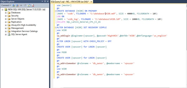
51. Click Execute and verify that the query executes successfully.
52. Close Microsoft SQL Server Management Studio.
53. Disconnect the Microsoft SQL Server 2012 ISO from the SQL Server VM.
Build and Set Up VMware vCenter Virtual Machine
Build VMware vCenter Virtual Machine
To build the VMware vCenter VM, follow these steps
1. Using the instructions for building a SQL Server VM provided in the section Build Microsoft SQL Server VM, build a VMware vCenter VM with the following configuration in the <<var_ib-mgmt_vlan_id>> VLAN:
— 12GB RAM
— Two CPUs
— One virtual network interface
2. Start the VM, install VMware Tools, and assign an IP address and host name to it in the Active Directory domain.
Set UP VMware vCenter Virtual Machine
To setup the newly built VMware vCenter VM, follow these steps:
1. Log into the vCenter VM as the admin user and open Server Manager.
2. Click Manage and then select Add Roles and Features to start the Add roles and Features Wizard.
3. Click Next.
4. On the Select installation screen, select Role-based or feature-based installation.
5. Select target Server and click Next.
6. Click Next on Server Roles.
7. On the Select Features screen, check the box .Net Framework 3.5 Features and click Next.
8. On the Confirm installation selections screen, a warning will be displayed asking Do you need to specify an alternate source path? If the target computer does not have access to Windows Update, click the Specify an alternate source path link to specify the path to the \sources\sxs folder on the installation media and then click OK. After you have specified the alternate source, or if the target has access to Windows update, Click the X next to the warning, and then click Install.
9. Click Close.
10. Click the following link Windows SQL Server 2012 SP1 Feature Pack.
11. Click Download.
12. Select the file name ENU\x64\sqlncli.msi and click Next.
13. Save it to a destination folder and run it.
14. On the Microsoft SQL Server 2012 Native Client Setup click Next.
15. Accept the license terms and click Next.
16. Click Next.
17. Click Install.
18. Click Finish.
19. Create the vCenter database data source name (DSN). Open Data Source (ODBC) by selecting Server Manager > Tools > ODBC Data Sources (64-bit).
20. Click the System DSN tab.
21. Click Add.
22. Choose SQL Server Native Client 11.0 and click Finish.
23. Name the data source VCDB. In the server , enter the IP address of the vCenter SQL server and
24. Click Next.
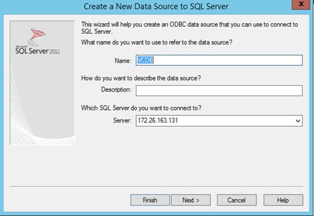
25. Choose With SQL Server authentication using a login ID and password entered by user. Enter vpxuser as the login ID and vpxuser password. Click Next.
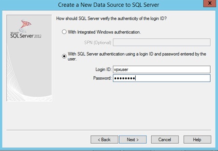
26. Choose Change the Default Database to and choose VCDB from the list. Click Next.
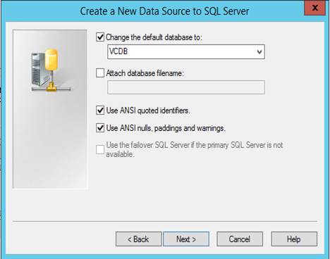
27. Click Finish.
28. Click Test Data Source. Verify that the test completes successfully.
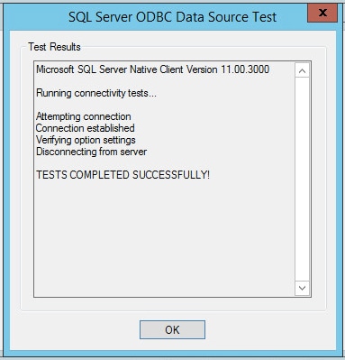
29. Click OK and then click OK again.
30. Click OK to close the ODBC Data Source Administrator (64-bit) window.
31. Install all available Microsoft Windows updates by right-clicking Start > Control Panel > Windows Update.
Install VMware vCenter Server
vCenter Server Virtual Machine
To install vCenter on the vCenter Server VM, complete the following steps:
1. In the vCenter Server VMware console, click the ninth button (CD with a wrench) to map the VMware vCenter ISO and choose Connect to ISO Image on Local Disk.
2. Navigate to the VMware vCenter 5.5 (VIMSetup) ISO, select it, and click Open.
3. In the dialog box, click Run autorun.exe
4. In the VMware vCenter installer window, make sure that VMware vCenter Simple Install is selected and click Install.
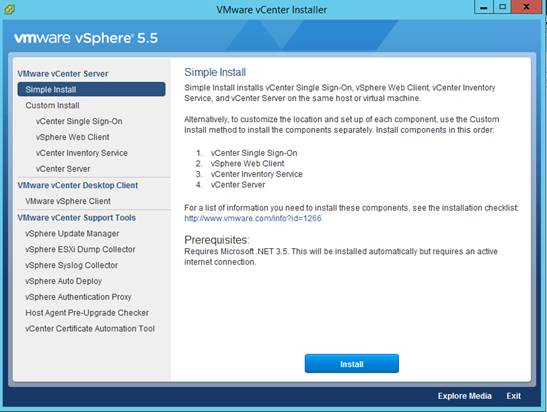
5. Click Next on the Welcome to the vCenter Single Sign-On Setup screen.
6. Accept the terms of the license agreement and click Next.
7. Click Next on Simple Install Prerequisites check screen.
8. Enter and confirm <<var_password>> for administrator@vsphere.local . Click Next.
9. Click Next on Simple Install Configure Site window.
10. Click Next on Simple Install Port Setting window.
11. Click Next on Change destination folder.
12. Review the installation option and click Install.
13. Enter the vCenter 5.5 license key and click Next.
14. Choose Use an Existing Supported Database. Choose VCDB from the Data Source Name list and click Next.
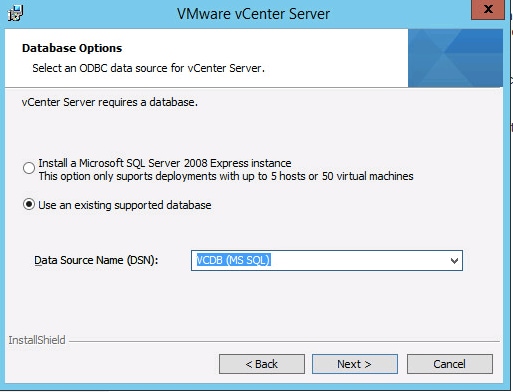
15. Enter the vpxuser password and click Next.
16. Click Next in the vCenter Server Service Window.
17. Click Next on Configure Ports screen
18. Choose the vCenter Server Configuration that best describes your setup. Click Next.
19. Choose the inventory size that that best describes your setup. Click Next.
20. Click Install.
21. Click Yes to accept and continue with SSL SHA1 SSO lookup Service Leaf certificate.
22. Click Install certificates.
23. Click Finish.
24. Click OK.
ESXI Dump Collector Setup
1. In the VMware vCenter Installer window, under vCenter Support Tools, select vSphere ESXi Dump Collector.
2. Click Install.
3. Select the appropriate language and click OK.
4. In the vSphere ESXi Dump Collector Installation Wizard, click Next.
5. Accept the terms in the License Agreement and click Next.
6. Click Next to accept the default Destination Folders.
7. Click Next to accept a Standalone installation
8. Click Next to accept the default ESXi Dump Collector Server Port (6500).
9. Select the VMware vCenter Server IP address from the drop-down menu. Click Next.
10. Click Install to complete the installation.
11. Click Finish.
12. Click Exit in the VMware vCenter Installer window.
13. Disconnect the VMware vCenter ISO from the vCenter VM.
![]() Note: A restart might be required.
Note: A restart might be required.
14. Back on the Management Workstation, search for Command Prompt and do a right-click the Command Prompt entry and then click Run as administrator option to open elevated Command Prompt.
15. For 64 bit OS go to C:\Program Files (x86)\VMware\Vmware vSphere CLI\bin directory and for 32 bit OS is C:\ProgramFiles\VMware\Vmware vSphere CLI\bin.
16. Set each ESXi Host to coredump to ESXi Dump Collector by running the following commands:
esxcli –s <<var_vm_host_infra_01_ip>> -u root –p <<var_password>> system coredump network set –-interface-name vmk0 –-server-ipv4 <<var_vcenter_server_ip>> --server-port 6500
esxcli –s <<var_vm_host_infra_02_ip>> -u root –p <<var_password>> system coredump network set –-interface-name vmk0 –-server-ipv4 <<var_vcenter_server_ip>> --server-port 6500
esxcli –s <<var_vm_host_infra_01_ip>> -u root –p <<var_password>> system coredump network set –-enable true
esxcli –s <<var_vm_host_infra_02_ip>> -u root –p <<var_password>> system coredump network set –-enable true
esxcli –s <<var_vm_host_infra_01_ip>> -u root –p <<var_password>> system coredump network check
esxcli –s <<var_vm_host_infra_02_ip>> -u root –p <<var_password>> system coredump network check
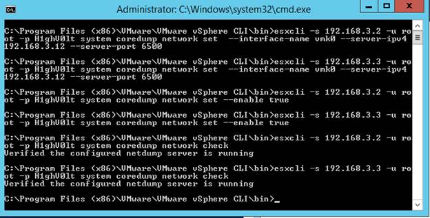
Log in to vSphere Web Client
1. Using a web browser, navigate to https:// <<var_vcenter_server_ip>>:9443/vsphere-client/#
2. Click Download the Client Integration Plug-in.
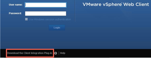
3. Click Run.
4. Closed the indicate browser and click Retry.
5. Click Next
6. Accept the license terms and click Next.
7. Click Next on Destination Folder window.
8. Click Install.
9. Click Finish.
10. Using a web browser, navigate to https:// <<var_vcenter_server_ip>>:9443/vsphere-client/#
11. In the user name type in administrator@vsphere.local and the administrator Password.
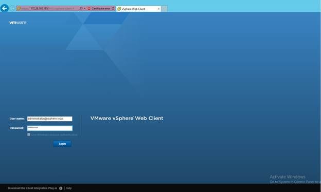
12. Click Login.
Adding the AD Account to Administrator Group
1. Log in to the vSphere Web Client as Administrator@vsphere.local.
2. From the home Location, navigate to >>Administration>>Single Sign-ON>>User and Groups>>.
3. In the right pane, select Groups.
4. Click Administrators on Group Name.
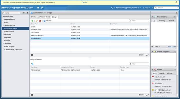
5. Click the + on Group Members.
6. Change the Domain to <<domain>>.
7. Highlight the Administrator and click Add.
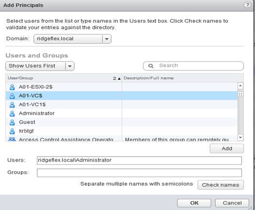
8. Click OK.
9. Navigate to >>Home>>vCenterServers and click your <<vcenter_server>>.
10. In the right pane, click the Manage tab.
11. Click Permissions tab.
12. Click the + sign.
13. Click Add.
14. Select your domain.
15. Highlight Administrator and double-clickit.
16. Click OK.
17. Change the Assigned Role to Administrator and click OK.
18. Log out from vSphere Web Client.
19. Login to the vSphere Web Client as Administrator@<<domain>>.
Set Up vCenter Center with a Datacenter, Cluster, DRS and HA
1. In the vSphere Web Client, navigate to the >>vCenter>>vCenter Servers>>vCenter_name.
2. Right-click the vCenter server and Select Actions > New Datacenter.
3. Rename the datacenter and click OK.
4. Browse to a datacenter in the vSphere Web Client navigator.
5. Right-click the datacenter and select New Cluster.
6. Select DRS and vSphere HA cluster features.
7. Select the DRS Turn ON check box.
8. Select the vSphere HA Turn ON check box.
9. Click OK.
Add Host to vCenter
1. In the vSphere Web Client, navigate to a datacenter, cluster, or folder within a datacenter.
2. Right-click the datacenter, cluster, or folder and select Add Host.
3. Type the IP address or the name of the host and click Next.
4. Type root credentials and click Next.
5. Click Yes to accept the certificate.
6. Review the host summary and click Next.
7. Assign a license key to the host Click Next.
8. (Optional) Select Enable Lockdown Mode to disable remote access for the administrator account after vCenter Server takes control of this host and click Next.
9. (Optional) If you add the host to a datacenter or a folder, select a location for the virtual machines that reside on the host and click Next.
10. Review the summary and click Finish.
ESXi Dump Collector Setup for iSCSI-Booted Hosts
ESXi hosts booted with iSCSI using the VMware iSCSI software initiator need to be configured to do core dumps to the ESXi Dump Collector that is part of vCenter. The Dump Collector is enabled by default on the vCenter Appliance.
1. On the Management Workstation, open the VMware vSphere CLI command prompt.
2. Set each iSCSI-booted ESXi Host to coredump to the ESXi Dump Collector by running the following commands:
esxcli –s <<var_vm_host_infra_01_ip>> -u root –p <<var_password>> system coredump network set –-interface-name vmk0 –-server-ipv4 <<var_vcenter_server_ip> --server-port 6500
esxcli –s <<var_vm_host_infra_02_ip>> -u root –p <<var_password>> system coredump network set –-interface-name vmk0 –-server-ipv4 <<var_vcenter_server_ip> --server-port 6500
esxcli –s <<var_vm_host_infra_01_ip>> -u root –p <<var_password>> system coredump network set –-enable true
esxcli –s <<var_vm_host_infra_02_ip>> -u root –p <<var_password>> system coredump network set –-enable true
esxcli –s <<var_vm_host_infra_01_ip>> -u root –p <<var_password>> system coredump network check
esxcli –s <<var_vm_host_infra_02_ip>> -u root –p <<var_password>> system coredump network check
This section provides a detailed procedure for configuring the Cisco APIC to communicate and control VMware Distributed Switch (VDS). In this section, VMware vCenter attachment to ACI will be covered.
Defining VMware Distributed Switch policies
In the Cisco UCS environment, VDS uplink configuration requires following three parameters to be explicitly set:
· No Port-Channel for uplink ports
· CDP used as the discovery protocol
· LLDP disabled as the discovery protocol
This configuration requires modifying the Access Entity Profiles (AEP) defined for Cisco UCS Fabric Interconnects.
1. From the top menu, select FABRIC.
2. Select ACCESS POLICIES from the sub menu.
3. From the left menu bar, expand Global Policies and Attachable Access Entity Profiles.
4. Select aep-<UCS_FI> where UCS_FI is the name used for UCS Fabric Interconnect profile in the previous sections.
5. On the right hand side, click Action and select Config vSwitch Policies.
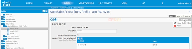
6. In the ‘CONFIG VSWITCH POLICIES dialog box, select CDP_Enable as the CDP Policy.
7. Select LACP_MAC_Pinning as the LACP Policy.
8. Select LLDP_Disabled as the LLDP Policy.
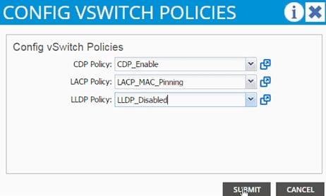
9. Click SUBMIT.
10. Verify the resulting AEP configuration.
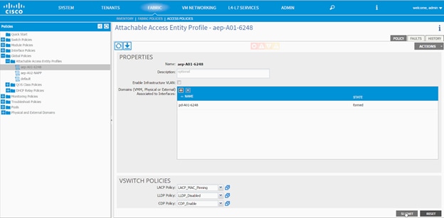
11. Click SUBMIT.
12. From the top menu, select VM NETWORKING.
13. Select POLICIES from the sub-menu.
14. From the left menu bar, click VM Provider VMware.
15. On the right side (under PROPERTIES) click + to add vCenter Domains.
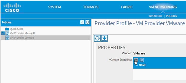
16. In the CREATE VCENTER DOMAIN dialog box, provide a Name to identify the vCenter.
17. Make sure VMWare vSphere Distributed Switch is selected as Virtual Switch.
18. From the drop-down menu for Associated Attachable Entity, select the AEP previously defined for UCS Fabric Interconnect.
19. From the drop-down menu next to VLAN Pool, select Create VLAN Pool.
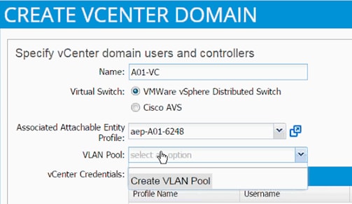
20. In the CREATE VLAN POOL dialog box, provide a name (e.g. vp-<NAME_of_vCenter> of the VLAN pool to be used for dynamically allocating VLANs to the EPGs.
21. Select Dynamic Allocation as the Allocation Mode.
22. Click + next to the Encap Blocks.
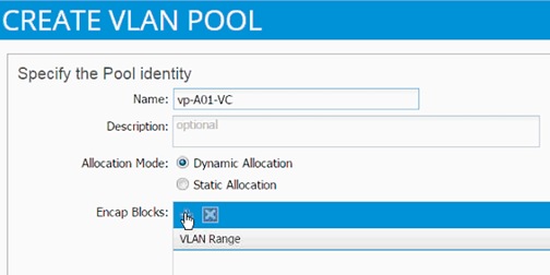
23. In the CREATE RANGES dialogue box add the VLAN range 1101 to 1200. (This range can be different depending on customer requirements).
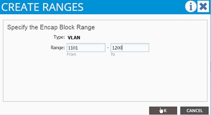
24. Click OK.
25. Click SUBMIT.
26. Click the + sign next to vCenter Credentials.
27. In the CREATE VCENTER CREDENTIALS dialog box, add vCenter Name.
28. Add admin username for vCenter in the following format: user@DOMAIN.
29. Add the password for the admin user and confirm the password.
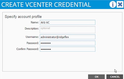
30. Click OK.
31. Click + next to vCenter/vShield.
32. In the CREATE VCENTER/VSHIELD CONTROLLER dialog box, select vCenter as the Type.
33. Add Name of the vCenter Controller.
34. Add DNS name or IP address in Hostname (or IP Address).
35. Select the DVS Version from the drop-down menu.
36. Select Enabled for the Stats Collection.
37. Type the name of the vCenter Datacenter – verify the name in the vCenter.
38. From the dropdown menu next to Associated Credentials, select the vCenter credentials defined in the previous steps.
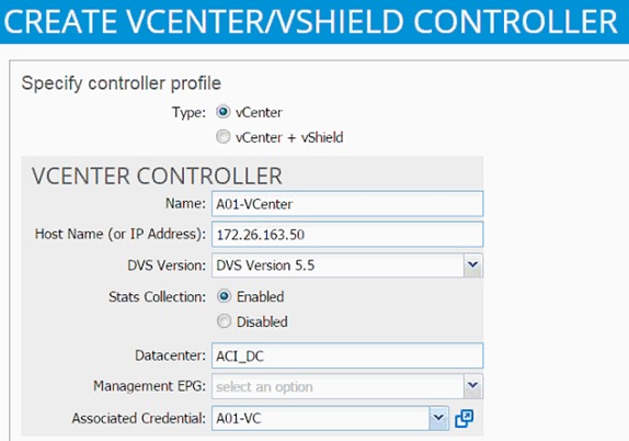
39. Click OK.
40. vCenter domain is now defined.
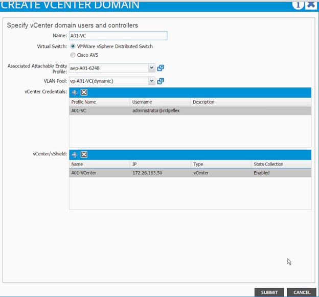
41. Click SUBMIT.
VMware Distributed Switch - Deployment Validation
Based on the communication defined in last section, Cisco APIC would define a new VDS in the vCenter. This can be verified using both Cisco APIC as well as VMware vCenter.
1. Log in to APIC, select VM NETWORKING from the top menu and INVENTORY from the submenu.
2. Expand VMware, vCenter and then DVS.
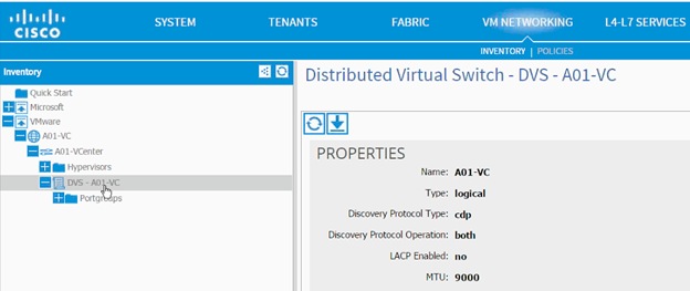
3. Validate the MTU size, LACP value (should be disabled) and Discovery Protocol (should be CDP).
4. Log in to the vCenter using the vSphere Client.
5. Browse to Networking. A new folder and VDS is available.
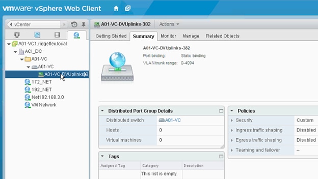
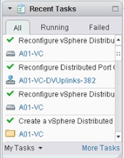
6. Right Click the Uplink PortGroup and click Edit Settings.
7. Click LACP.
8. Validate the Status is Disabled.
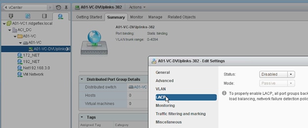
Adding Hosts to VMware Distributed Switch
While Cisco APIC defines and configured the VDS automatically based on the user configuration, The ESXi hosts need to be added to the VDS and Uplinks need to be defined manually. For this configuration, VMware provided wizard would be utilized
1. From the networking tab in vSphere web client, right click on the VDS and click Add and Manage Hosts…
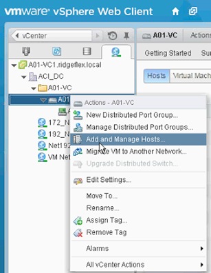
2. In the Add and Manage Hosts wizard, select Add hosts and click Next.
3. Click + to add New hosts.
4. Select all the hosts that need to be part of the VDS.
5. Click OK.
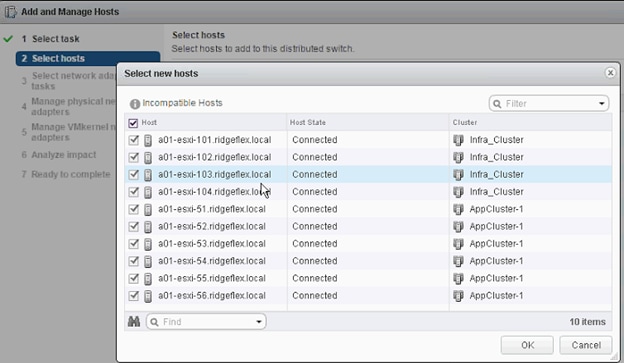
6. Click Next.
7. In the Select network adapter tasks, make sure only Manage Physical adapter tasks is selected.
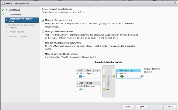
8. Click Next.
9. On the Manage physical network adapters screen, for all the hosts select vmnic 0 and vmnic 1 to the uplink ports.
10. Click Next.
11. Analyze the impact (number of adapters being added) and click Finish.
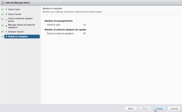
12. When the update is completed, click the Uplink port-group and validate the correct number of hosts were added to VDS.
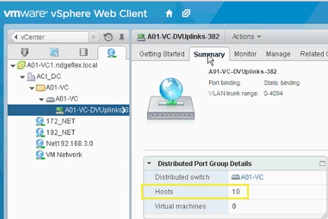
Application Profile vMotion
In this section, an Application Profiles for vMotion traffic will be created. All ESXi hosts will be configured with a VMkernel Port to act as vMotion interface.
vMotion - Application Profile Creation
1. Go to Tenant menu and select Foundation tenant from the top menu.
2. Expand Tenant Foundation in the left menu bar.
3. Right-click Application Profile and click Create Application Profiles.
4. In the CREATE APPLICATION PROFILE dialog box, enter vMotion as the Name.
5. From the drop-down menu, select default for Monitoring Policy.
6. Click + next to EPG to add an EPG.
7. Enter vmk-vmotion as the EPG Name.
8. Select bd_Internal as the Bridge Domain.
9. Select default as the Monitoring Policy.
10. Click + next to Associated Domain Profile (VMs or bare metals):
11. From the drop-down menu, select A01-VC (recently created VMM domain).
12. Set Deployment Immediacy and Resolution Immediacy to Immediate.
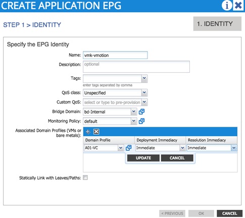
13. Click Update.
14. Click OK.
15. Click SUBMIT.
16. On vCenter Client, under Home -> Inventory -> Networking, make sure a port group Foundation|vMotion|vmk-vmotion is added.
17. On all the ESXi servers, add a VMKernel port, attach it to the above port-group, set the MTU to 9000 and enable vMotion traffic.
This section provides a detailed procedure for configuring a tenant (Business Unit or Application) using ACI as follows:
· An SVM will be deployed for tenant (named App-A)
· An Application tenant will be created on APIC (named App-A)
· NFS access will be established
· NFS Datastore will be mounted onto the Application ESXi servers for VM deployment
The procedures above will showcase interworking of Cisco APIC and VMware VDS. Communication between this tenant and an existing infrastructure (outside ACI fabric) will be enabled using OSPF routing.
Application Specific SVM Creation
VLAN in Clustered Data ONTAP
1. Create NFS VLANs.
network port vlan create –node <<var_node01>> -vlan-name a0a-<<var_nfs_vlan_id>>
network port vlan create –node <<var_node02>> -vlan-name a0a-<<var_nfs_vlan_id>>
2. Create iSCSI VLANs.
network port vlan create –node <<var_node01>> -vlan-name a0a-<<var_iscsi_vlan_A_id>>
network port vlan create –node <<var_node01>> -vlan-name a0a-<<var_iscsi_vlan_B_id>>
network port vlan create –node <<var_node02>> -vlan-name a0a-<<var_iscsi_vlan_A_id>>
network port vlan create –node <<var_node02>> -vlan-name a0a-<<var_iscsi_vlan_B_id>>
3. Create SVM Management VLANs.
network port vlan create –node <<var_node01>> -vlan-name a0a-<<var_svm_mgmt_vlan_id>>
network port vlan create –node <<var_node02>> -vlan-name a0a-<<var_svm_mgmt_vlan_id>>
Broadcast Domains in Clustered Data ONTAP
1. Create NFS Broadcast Domain.
broadcast-domain create –broadcast-domain App-A-NFS –mtu 9000 -ports <<var_node01>>:a0a-<<var_nfs_vlan_id>>,<<var_node02>>:a0a-<<var_nfs_vlan_id>>
2. Create iSCSI Broadcast Domains.
broadcast-domain create –broadcast-domain App-A-iSCSI-A –mtu 9000 -ports <<var_node01>>:a0a-<<var_iscsi_vlan_A_id>>,<<var_node02>>:a0a-<<var_iscsi_vlan_A_id>>
broadcast-domain create –broadcast-domain App-A-iSCSI-B –mtu 9000 -ports <<var_node01>>:a0a-<<var_iscsi_vlan_B_id>>,<<var_node02>>:a0a-<<var_iscsi_vlan_B_id>>
3. Create SVM Management Broadcast Domain.
broadcast-domain create –broadcast-domain App-A-MGMT –mtu 1500 -ports <<var_node01>>:a0a-<<var_svm_mgmt_vlan_id>>,<<var_node02>>:a0a-<<var_svm_mgmt_vlan_id>>
Storage Virtual Machine (Vserver)
![]() Note: The storage virtual machine (SVM) is referred to as Vserver (or vserver) in the GUI and CLI.
Note: The storage virtual machine (SVM) is referred to as Vserver (or vserver) in the GUI and CLI.
1. Run the vserver create command.
vserver create –vserver App-A-SVM –rootvolume rootvol –aggregate aggr1_node01 –rootvolume-security-style unix
2. Select the SVM data protocols to configure, keeping nfs and iscsi.
vserver remove-protocols –vserver App-A-SVM -protocols fcp,cifs,ndmp
3. Add the two data aggregates to the Infra-SVM aggregate list for NetApp Virtual Storage Console (VSC).
vserver modify –vserver App-A-SVM –aggr-list aggr1_node01,aggr1_node02
4. Enable and run the NFS protocol in the Infra-SVM.
nfs create -vserver App-A-SVM -udp disabled
5. Turn on the SVM vstorage parameter for the NetApp NFS VAAI plugin.
vserver nfs modify –vserver App-A-SVM –vstorage enabled
vserver nfs show
Create Load Sharing Mirror of Vserver Root Volume in Clustered Data ONTAP
To create a load-sharing mirror of an SVM root volume, complete the following steps:
![]() Note: The storage virtual machine (SVM) is referred to as Vserver (or vserver) in the GUI and CLI.
Note: The storage virtual machine (SVM) is referred to as Vserver (or vserver) in the GUI and CLI.
1. Create a volume to be the load-sharing mirror of the infrastructure SVM root volume on each node.
volume create –vserver App-A-SVM –volume rootvol_m01 –aggregate aggr1_node01 –size 1GB –type DP
volume create –vserver App-A-SVM –volume rootvol_m02 –aggregate aggr1_node02 –size 1GB –type DP
2. Create the mirroring relationships.
snapmirror create –source-path //App-A-SVM/rootvol –destination-path //App-A-SVM/rootvol_m01 –type LS -schedule 15min
snapmirror create –source-path //App-A-SVM /rootvol –destination-path //App-A-SVM/rootvol_m02 –type LS -schedule 15min
3. Initialize the mirroring relationship.
snapmirror initialize-ls-set –source-path //App-A-SVM/rootvol
snapmirror show
iSCSI Service in Clustered Data ONTAP
1. Create the iSCSI service on each Vserver. This command also starts the iSCSI service and sets the iSCSI alias to the name of the Vserver.
iscsi create -vserver App-A-SVM
iscsi show
HTTPS Access in Clustered Data ONTAP
Secure access to the storage controller must be configured. To configure secure access, complete the following steps:
1. Increase the privilege level to access the certificate commands.
set -privilege diag
Do you want to continue? {y|n}: y
2. Generally, a self-signed certificate is already in place. Check it by using the following command:
security certificate show
3. For the App-A Vserver, the certificate common name should match the DNS FQDN of the Vserver. The four default certificates should be deleted and replaced by either self-signed certificates or certificates from a Certificate Authority (CA) To delete the default certificates, run the following commands:
![]() Note: Deleting expired certificates before creating new certificates is best practice. Run the security certificate delete command to delete expired certificates. In the command below, use TAB completion to select and delete each default certificate.
Note: Deleting expired certificates before creating new certificates is best practice. Run the security certificate delete command to delete expired certificates. In the command below, use TAB completion to select and delete each default certificate.
security certificate delete [TAB] …
Example: security certificate delete -vserver App-A-SVM -common-name 3.cert.1414163766 -ca 3.cert.1414163766 -type server -serial 544A6D36
4. To generate and install a self-signed certificate, run the following command as a one-time command. Generate a server certificate for the App-A Vserver. Again, use TAB completion to aid in completing these commands.
security certificate create [TAB] …
Example: security certificate create -common-name app-a-svm.ridgeflex.local -type server -size 2048 -country US -state "North Carolina" -locality "RTP" -organization "Cisco" -unit "SAVBU" -email-addr "abc@cisco.com" -expire-days 365 –protocol SSL -hash-function SHA256 –vserver App-A-SVM
5. To obtain the values for the parameters that would be required in the following step, run the security certificate show command.
6. Enable each certificate that was just created using the –server-enabled true and –client-enabled false parameters. Again use TAB completion.
security ssl modify [TAB] …
Example: security ssl modify -vserver App-A-SVM -server-enabled true -client-enabled false -ca app-a-svm.ridgeflex.local -serial 544A71D7 -common-name app-a.ridgeflex.local
7. Change back to normal admin privilege level and set up to allow Vserver logs to be available by web.
set –privilege admin
vserver services web modify –name spi|ontapi|compat –vserver * -enabled true
NFSv3 in Clustered Data ONTAP
To configure NFS on the Vserver, run all commands.
1. Modify the initial default rule for the SVM NFS subnet in the default export policy.
vserver export-policy rule create –vserver App-A-SVM -policyname default –ruleindex 1 –protocol nfs -clientmatch <<var_nfs_subnet_address>> -rorule sys –rwrule sys -superuser sys –allow-suid false
vserver export-policy rule show
2. Assign the FlexPod export policy to the App-A Vserver root volume.
volume modify –vserver App-A-SVM –volume rootvol –policy default
FlexVol in Clustered Data ONTAP
1. The following information is required to create a FlexVol® volume: the volume’s name and size, and the aggregate on which it will exist. Create two NFS VMware datastore volumes and an iSCSI LUN volume. Also, update the Vserver root volume load sharing mirrors to make the NFS mounts accessible.
volume create -vserver App-A-SVM -volume app_a_datastore_1 -aggregate aggr1_node2 -size 500GB -state online -policy default -junction-path /app_a_datastore_1 -space-guarantee none -percent-snapshot-space 0
volume create -vserver App-A-SVM -volume iSCSI_LUN -aggregate aggr1_node1 -size 100GB -state online -policy default -space-guarantee none -percent-snapshot-space 0
snapmirror update-ls-set -source-path //App-A-SVM/rootvol
Deduplication in Clustered Data ONTAP
1. Enable deduplication on appropriate volumes.
volume efficiency on –vserver App-A-SVM -volume app_a_datastore_1
volume efficiency on –vserver App-A-SVM -volume iSCSI_LUN
NFS LIF in Clustered Data ONTAP
1. Create an NFS logical interface (LIF).
network interface create -vserver App-A-SVM -lif nfs_app_a_datastore_1 -role data -data-protocol nfs -home-node <<var_node02>> -home-port a0a-<<var_nfs_vlan_id>> –address <<var_node02_nfs_lif_app_a_datastore_1_ip>> -netmask <<var_node02_nfs_lif_app_a_datastore_1_mask>> -status-admin up –failover-policy broadcast-domain-wide –firewall-policy data –auto-revert true –failover-group App-A-NFS
![]() Note: It is recommended to create a new lif for each datastore.
Note: It is recommended to create a new lif for each datastore.
iSCSI LIF in Clustered Data ONTAP (Optional)
1. Create iSCSI logical interfaces (LIFs).
network interface create -vserver App-A-SVM -lif iscsi_lif01a -role data -data-protocol iscsi -home-node <<var_node01>> -home-port a0a-<<var_iscsi_vlan_A_id>> –address <<var_node01_iscsi_lif01a_ip>> -netmask <<var_node01_iscsi_lif01a_mask>> -status-admin up -failover-policy disabled -firewall-policy data -auto-revert false
network interface create -vserver App-A-SVM -lif iscsi_lif01b -role data -data-protocol iscsi -home-node <<var_node01>> -home-port a0a-<<var_iscsi_vlan_B_id>> –address <<var_node01_iscsi_lif01b_ip>> -netmask <<var_node01_iscsi_lif01b_mask>> -status-admin up -failover-policy disabled -firewall-policy data -auto-revert false
network interface create -vserver App-A-SVM -lif iscsi_lif02a -role data -data-protocol iscsi -home-node <<var_node02>> -home-port a0a-<<var_iscsi_vlan_A_id>> –address <<var_node02_iscsi_lif02a_ip>> -netmask <<var_node02_iscsi_lif02a_mask>> -status-admin up -failover-policy disabled -firewall-policy data -auto-revert false
network interface create -vserver App-A-SVM -lif iscsi_lif02b -role data -data-protocol iscsi -home-node <<var_node02>> -home-port a0a-<<var_iscsi_vlan_B_id>> –address <<var_node02_iscsi_lif02b_ip>> -netmask <<var_node02_iscsi_lif02b_mask>> -status-admin up -failover-policy disabled -firewall-policy data -auto-revert false
network interface show –vserver App-A-SVM
Add App-A Vserver Administrator
1. Add the App-A Vserver administrator and Vserver administration logical interface in the SVM management network with the following commands:
network interface create –vserver App-A-SVM –lif vsmgmt –role data –data-protocol none –home-node <<var_node02>> -home-port a0a-<<var_svm_mgmt_vlan_id>> –address <<var_vserver_mgmt_ip>> -netmask <<var_vserver_mgmt_mask>> -status-admin up –failover-policy broadcast-domain-wide –firewall-policy mgmt –auto-revert true –failover-group App-A-MGMT
network route create –vserver App-A-SVM -destination 0.0.0.0/0 –gateway <<var_vserver_mgmt_gateway>>
network route show
security login password –username vsadmin –vserver App-A-SVM
Enter a new password: <<var_vsadmin_password>>
Enter it again: <<var_vsadmin_password>>
security login unlock –username vsadmin –vserver App-A-VSM
Application Tenant Creation on APIC
1. From the main menu, click TENANTS and from the sub-menu click ADD TENANT.
2. In the CREATE TENANT dialog box, type <Name of Application> as the name of the tenant. This example used App-A as the name of the tenant.
3. Click the checkbox next to all under Security Domains.
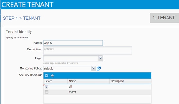
4. Click Next.
5. Click the + sign to add network.

6. In the CREATE NEW NETWORK dialog box, type App-A as the Name. Leave everything else as default.
7. Click Next to move onto bridge domain creation.
8. Use bd-Internal as the Name of the bridge domain.
9. Select default for IGMP Snoop Policy.
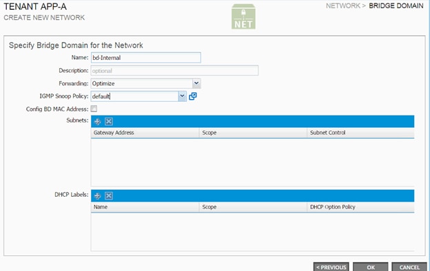
10. Click OK.
11. The Bridge Domains and App-A network should be visible in the CREATE TENANT dialog box.
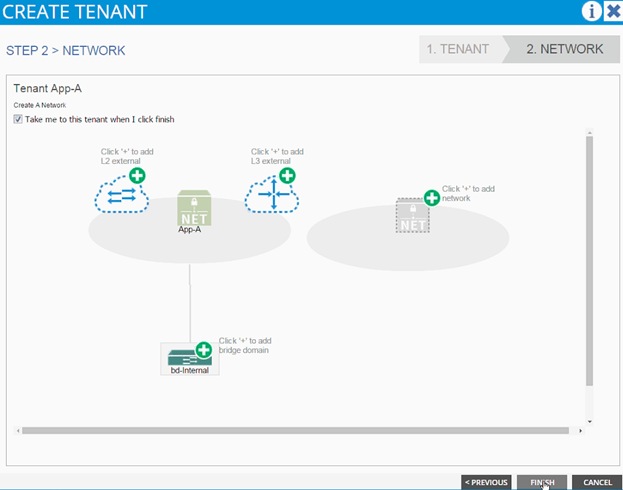
12. Click Finish.
13. Verify the selected tenant is the newly created App-A tenant by looking at the items highlighted in the top menu.

3-Tier App - Application Profile Creation and Adding EPG for Web Tier
To create an Application Profile to host the application, complete the following steps:
1. Select Tenant and newly created App-A tenant from the top menu.
2. Expand Tenant App-A in the left menu bar.
3. Right-click Application Profile and click Create Application Profile.
4. In the CREATE APPLICATION PROFILE dialog box, enter 3-Tier-App as the Name.
5. From the drop-down menu, select default for Monitoring Policy.
6. Click + next to EPG to add an EPG.
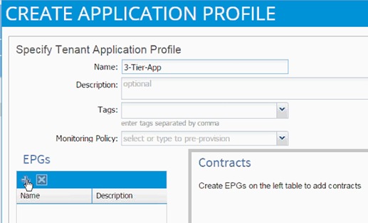
7. In the CREATE APPLICATION EPG dialog box, enter Web as the Name.
8. From the drop-down menu, select bd-Internal as the Bridge Domain.
9. From the drop-down menu, select default for Monitoring Policy.
10. Click OK.
11. Click + next to Associated Domain Profiles (VMs or Bare metals).
12. From the drop-down menu, select the VMM domain previously defined.
13. Select Immediate for Deployment Immediacy.
14. Select Immediate for Resolution Immediacy.
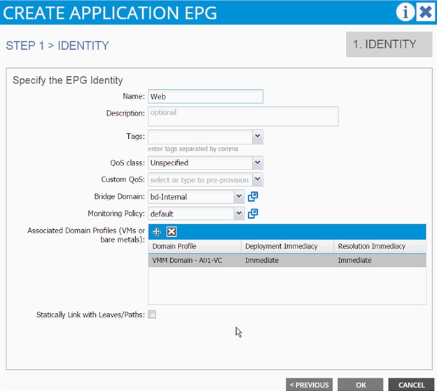
15. Click UPDATE.
16. Click OK.
17. Click SUBMIT to finish creating Application Profile.
18. Expand the newly created EPG Web and click Subnets.
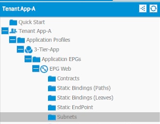
19. Click the Action menu on the right and select Create EPG Subnet.

20. Enter 10.10.1.254/24 for the Default Gateway IP. This IP address is the gateway that all the Web VMs will use.
21. Change scope to only Shared Subnet.
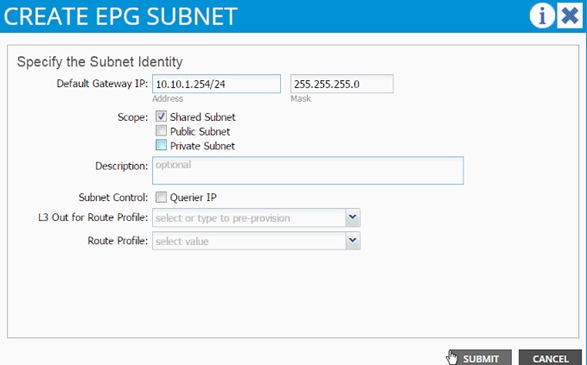
22. Click SUBMIT.
Port-Group Deployment Validation
When an EPG is tied to a VMM domain (previous section), a port-group gets created on the VDS so that application admin can deploy his virtual machine and make it part of the application tier just defined. A dynamic VLAN is associated with this newly created EPG/port-group. To validate the configuration, complete the following steps:
1. Browse to the VM NETWORKING and on the left menu bar, drill down to VDS to list the port-groups. As seen from the figure, VLAN 1135 from the pre-defined range 1101-1200 was assigned to the newly create port-group.
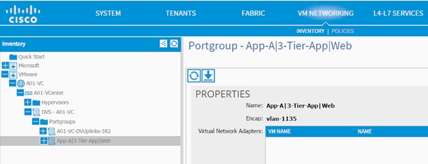
2. Browse to FABRIC and in the left menu bar, expand the Leaf, Interface, vPC Interfaces and domain 10. Click the vPC associated with UCS Fabric Interconnect.
3. VLAN 1135 should have been added to the vPC VLANs.
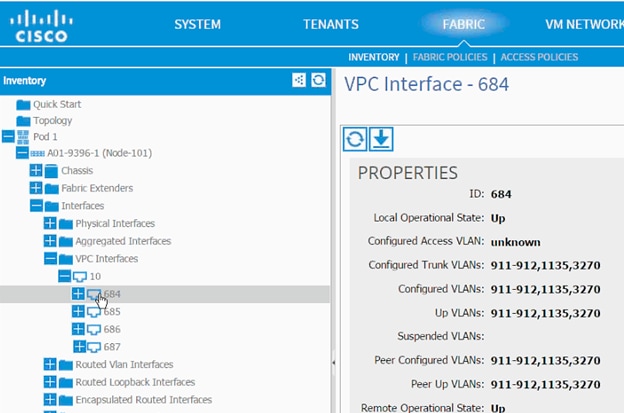
4. Log into the vCenter and browse to the VDS. Right-click the newly added port-group and click Teaming and Failover.
5. Validate Load balancing method is Route based on originating virtual port (VMware default).
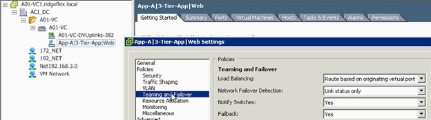
6. Validate the VLAN assigned is 1135.
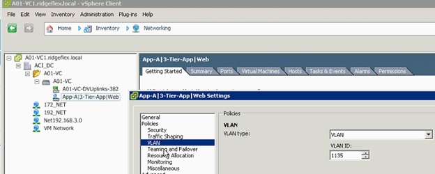
Modifying the Storage (NetApp) Physical Domain VLANs
Physical domain associated with NetApp storage was initially configured for infrastructure iSCSI and NFS VLANs. In this step, NFS and iSCSI VLANs associated with App-A SVM will be added to the physical domain. To add to the physical domain, complete the following steps:
1. Select Fabric and Access Policies from the top menu.
2. Expand Pools and then VLAN.
3. Click the pool name associated with NetApp controllers (vp-A01-NetApp in this example) and click + to add another Encap Block.
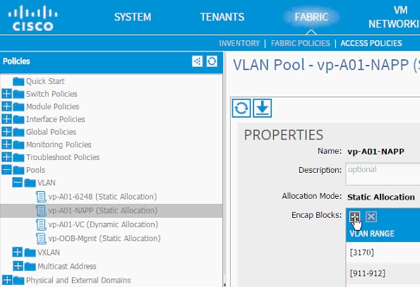
4. Enter <<var_nfs_vlan_tenant>> (3180 to 3180 in this example) as the range of VLANs for Tenant NFS.
5. (Optional) Add the range of VLANs for iSCSI-a and iSCSI-b. If configuring the tenant for iSCSI access.
6. Click SUBMIT.
NFS - Application Profile Creation
In this section, you will create an Application Profile to setup NFS connectivity between the ESXi servers and the Application specific SVM. An NFS datastore will then be mounted to host application specific VMs. To create the application profile, complete the following steps:
1. Select Tenant and App-A tenant from the top menu.
2. Expand Tenant App-A in the left menu bar.
3. Right-click Application Profile and click Create Application Profile.
4. In the CREATE APPLICATION PROFILE dialog box, enter NFS as the Name.
5. From the drop-down menu, select default for Monitoring Policy.
6. Click + next to EPG to add an EPG.
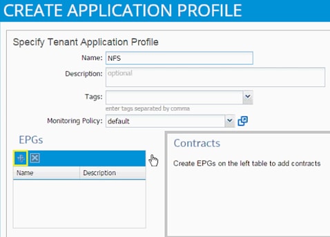
7. In the CREATE APPLICATION EPG dialog box, enter vmk-nfs as the Name.
8. From the drop-down menu, select bd-Internal as the Bridge Domain.
9. From the drop-down menu, select default for Monitoring Policy.
10. Click OK.
11. Click + next to Associated Domain Profiles (VMs or Bare metals).
12. From the drop-down menu, select the VMM domain previously defined.
13. Select Immediate for Deployment Immediacy.
14. Select Immediate for Resolution Immediacy.
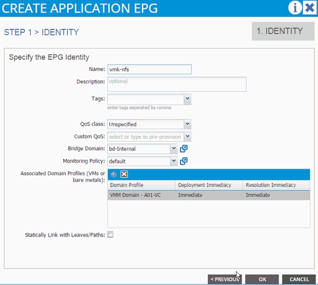
15. Click UPDATE.
16. Click OK.
17. Click + next to EPG to add another EPG.
18. In the CREATE APPLICATION EPG dialog box, enter lif-nfs as the Name.
19. From the drop-down menu, select bd-internal as the Bridge Domain.
20. From the drop-down menu, select default for Monitoring Policy.

21. Click OK.
22. Click SUBMIT to finish creating Application Profile.
23. Expand the newly created NFS Application profile from the menu bar on the left.
24. Expand NFS, expand Application EPGs and expand EPG lif-nfs.
25. Click Static Bindings (Paths).
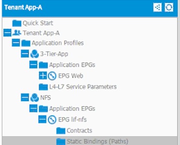
26. Click Action.
27. Click Deploy Static EPG on PC, vPC, or Interface.
28. In the DEPLOY STATIC EPG ON PC, vPC OR INTERFACE dialog box, select Virtual Port Channel as the Path Type.
29. From the drop-down menu Path, select NetApp Controller 1.
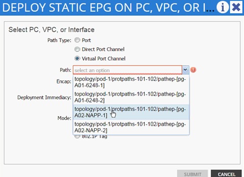
30. Enter vlan-<App-A-NFS LIF VLAN> for Encap (VLAN 3180 is the NFS VLAN on NetApp Controller in the screen capture below).
31. Change Deployment Immediacy to Immediate.

32. Click Submit.
33. Repeat these steps for mapping NetApp Controller 2 path.
34. Static bindings should be similar to screenshot below.
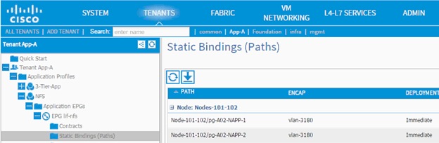
35. Click Contracts under the EPG lif-nfs.
36. Click Action and select Add Provided Contract.
37. From the ADD PROVIDED CONTRACT dialog box, select Create Contract under Contract.
38. Enter Allow-NFS as Name in the CREATE CONTRACT dialog box.
39. Click + next to Subjects to add a new contract subject.
40. In the CREATE CONTRACT SUBJECT dialog box, enter Allow-All as the Name.
41. Click + under Filter Chain to add a new filter.
42. Drop down the menu under FILTERS and click +.
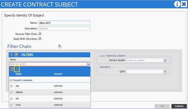
43. In the CREATE FILTER dialog box, enter Allow-All as the Name. In this example, we will allow all the traffic for this contract.
44. Click + to add a filter.
45. Enter Allow-All as the name of the filter.
46. From drop-down menu, select IP as Ethertype.
47. Click Update.
48. Click SUBMIT to create the filter.
49. Click UPDATE to add the newly created filter to the filter chain.
50. Click OK to finish creating the Contract Subject.
51. Click SUBMIT.
52. Click SUBMIT again to finish adding a provided contract.
53. Verify the Provided Contract appears under the Contracts.
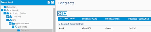
54. Expand EPG vmk-nfs.
55. Click Contracts in the left menu.
56. Click ACTIONS on the right and select Add Consumed Contract.
57. In the ADD CONSUMED CONTRACT dialog box, from the drop-down menu select App-A/Allow-NFS contract.
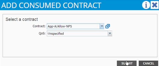
58. Click SUBMIT.
iSCSI Application Profile Creation (Optional)
If an application requires access to block based storage using iSCSI, steps from previous sections can be repeated to:
· Define two Bridge Domains – bd-iSCSI-a and bd-iSCSI-b
· Define an Application Profile called iSCSI
· Define four EPGs called lif-iSCSI-a, lif-iSCSI-b, vmk-iSCSI-a and vmk-iSCSI-b
· Use separate bridge domains for iSCSI-a and iSCSI-b EPGs
· Attach the vmk specific EPGs to the VMM domain
· Attach the lif specific EPGs to static VLAN path mappings
· Define the contracts to enable communication between iSCSI-a and iSCSI-b vmk and lif EPGs
· Define VMkernel ports on the VMware vDS for iSCSI-a and iSCSI-b.
· Add the storage SVM targets in the VMware iSCSI software initiator.
Defining NFS VMKernel Port and Mounting the Datastore
In the previous section, NFS communication between the Application SVM and ESXi servers was set up. In this section, a VMkernel port will be defined on ESXi servers and NFS datastore will be mounted to host application specific VMs.
1. Select ESXi server in the vSphere Client. Click Configuration and then Networking.
2. Click vSphere Distributed Switch.
3. Click Manage Virtual Adapters.
4. Click Add to add VMkernel Port.
5. Select New virtual adapter. Click Next.
6. Click Next.
7. Select App-A|NFS|vnk-nfs from drop-down menu for Select port group.
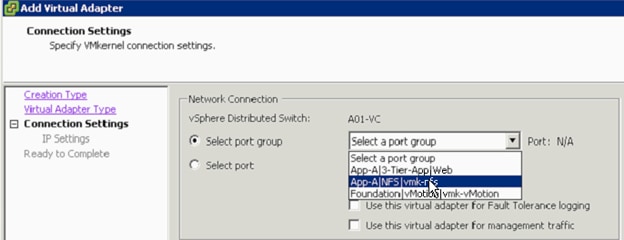
8. Click Next.
9. Enter the NFS VMkernel Port IP address in the same subnet as the NetApp LIF defined earlier.
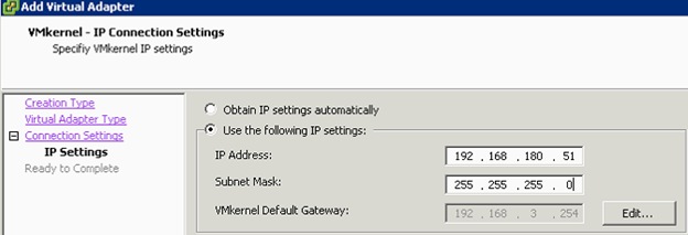
10. Click Next.
11. Click Finish.
12. Click newly created vmk port and click Edit.
13. Set the MTU to 9000.
14. Click OK.
15. Click Close to finish setting up the VMkernel port.
16. Click Storage under settings.
17. Click Add Storage.
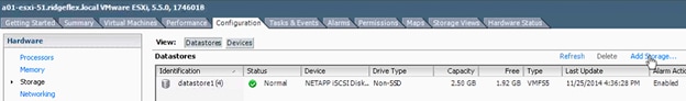
18. Select Network File System.
19. Click Next.
20. Provide the SVM LIF address, path and datastore name for the predefined NFS datastore.
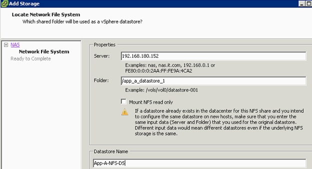
21. Click Next.
22. Verify information and click Finish.
Defining EPGs for additional Application Tiers (Optional)
In the previous section, an application profile 3-Tier-App was defined and an EPG Web was deployed. To define EPGs for additional tiers of the application, complete the following steps:
1. Expand Application Profiles for Tenant App-A.
2. Right-click 3-Tier-App and select Create Application EPG.
3. Provide the name of the Application Tier EPG (App in this example).
4. From the drop-down menu, select bd-Internal as the Bridge Domain.
5. Select Monitoring Policy as default.
6. Click + to add Associated Domain Profiles (VMs or bare metals) and select vCenter domain.
7. Change Deployment Immediacy and Resolution Immediacy to Immediate.
8. Click UPDATE.
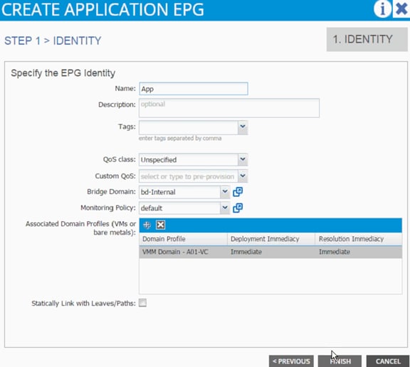
9. Click FINISH.
10. Expand the newly created EPG App and click Subnets.
11. Click the Action menu on the right and select Create EPG Subnet.
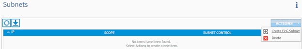
12. Enter 10.10.2.254/24 for the Default Gateway IP. This IP address is the gateway that all the App VMs will use. (Please adjust this subnet according to your implementation).
13. Change scope to only Shared Subnet.
14. Click FINISH.
15. Repeat these steps for additional EPG (application tier) definitions.
Enabling Communication Between Application Tiers
If an application tier needs to communicate to another application tier, a contract needs to be provided by one EPG and consumed by the other. In this example, previously defined App EPG will provide a contract and Web EPG will consume the contract. The ports on which the two application tiers can be limited in the contract subject but for this example, all communication will be allowed between the two tiers.
To enable communication between application tiers, complete the following steps:
1. Expand the Application Profile 3-Tier-App, Application EPGs and EPG App.
2. Click Contracts under the EPG App.
3. Click Action and select Add Provided Contract.
4. From the ADD PROVIDED CONTRACT dialog box, select Create Contract under Contract.
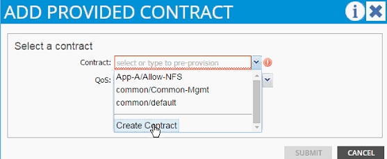
5. Enter Allow-App-Web as Name in the CREATE CONTRACT dialog box.
6. Click + next to Subjects to add a new contract subject.
7. In the CREATE CONTRACT SUBJECT dialog box, enter Allow-All as the Name.
8. Click + under Filter Chain to add a new filter.

9. Drop down the menu under FILTERS and click +.
10. In the CREATE FILTER dialog box, enter Allow-All as the Name. In this example, we will allow all the traffic for this contract.
11. Click + to add a filter.

12. Enter Allow-All as the name of the filter.
13. From drop-down menu, select IP as Ethertype.
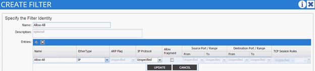
14. Click Update.
15. Click SUBMIT to create the filter.
16. Click UPDATE to add the newly created filter to the filter chain.
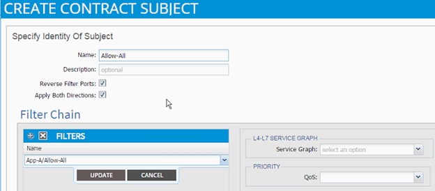
17. Click OK to finish creating the Contract Subject.
18. Click SUBMIT.
19. Click SUBMIT again to finish adding a provided contract.
20. Expand EPG Web.
21. Click Contracts in the left menu.
22. Click ACTIONS on the right and select Add Consumed Contract.
23. In the ADD CONSUMED CONTRACT dialog box, from the drop-down menu select App-A/Allow-App-Web contract.
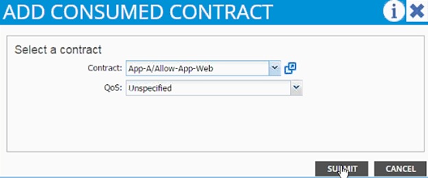
24. Click SUBMIT.
Deploying Virtual Machines
After going through several configuration steps above, application related VMs could be deployed using vSphere client. VMware distributed switched managed using APIC will show port-groups for the Application EPGs defined in previous steps. The Web-tier VMs will be deployed and connected to the port-group labeled App-a|3-Tier-App-Web. VM related to other application tiers will be deployed in their respective port-groups. The resulting VDS configuration for an ESXi host will look like Figure 5. As the name suggests, App-A-Web is the web-VM while App-A-App is the application VM.
Figure 5 ESXi – VDS Deployment Example for Application VMs
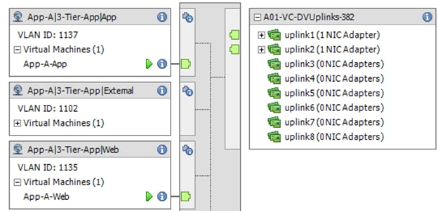
This section provides a detailed procedure for configuring access to common services such as AD, DNS and in some cases vCenter etc. The leaf switches in the ACI fabric connect to an existing management switch where common service servers or VMs are connected using a dedicated LAN segment (VLAN 3177 in this case). This management segment is then mapped to an EPG in the common tenant using static VLAN mappings. In ACI, any contracts defined and provided in the common tenant can be consumed in any all other tenants and this makes common tenant an ideal candidate to host the common services management EPGs.
Configuring ACI for Management Switch
To configure vPC for management switch, complete the following steps:
1. From the main menu, click FABRIC and select Access Policies.
2. Right-click Interface Policies and select Configure interface, PC and vPC.
3. In the dialog box, click + under the CONFIGURED SWITCH INTERFACES.
4. Drop down the menu next to Switches and select both leaves.

5. Enter <sp-OOB-Mgmt> as Switch Profile Name. OOB-Mgmt is the host name for management switch.
6. Click the + sign to add interfaces.
7. Select vPC radio button to configure vPC.
8. Enter 1/21 under Interfaces. This is the port on both switches where existing management switch is connected.
9. Enter <ifs- OOB-Mgmt> as Interface Selector Name.
10. Drop down vPC Policy Group and click Create vPC Interface Policy Group. A new dialog box will appear.
11. Enter <pg- OOB-Mgmt> as the name of the vPC INTERFACE POLICY GROUP in the dialog box.
12. From the drop-down menu Link Level Policy, select Create Link Level Policy.
13. In the CREATE LINK LEVEL POLICY, enter 1_GE as the Name.
14. Select 1 Gbps as the Speed.
15. Click SUBMIT.
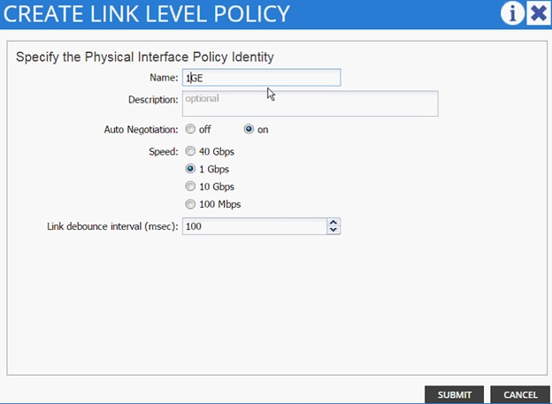
16. Select CDP_Enabled as CDP Policy.
17. Select LLDP_Disabled as LLDP Policy.
18. Select default as STP Interface Policy.
19. Select LACP_ACTIVE as LACP Policy.
20. Select default as Monitoring Policy.
21. Drop down Attached Entity Profile and click Create Attachable Access Entity Profile. A new dialog box will appear.
22. Enter <aep-OOB-Mgmt> as the Name.
23. Click + to add Domain.
24. In the added domain, drop-down the menu and select Create Layer 2 Domain.
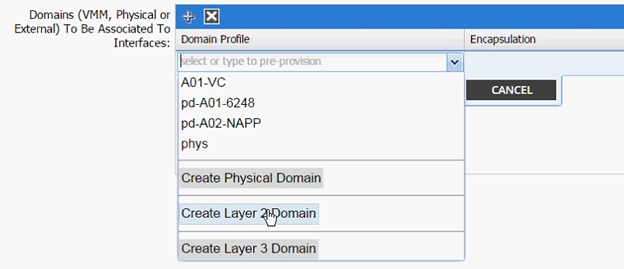
25. In the Create Layer 2 Domain dialog box, enter <L2-OOB-Mgmt> as Name.
26. Drop down VLAN Pool menu and select Create VLAN Pool.
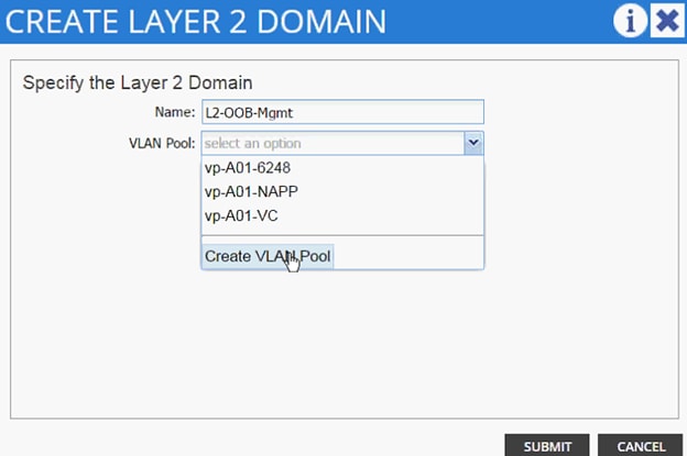
27. In the Create VLAN Pool dialog box, enter <vp-OOB-Mgmt> as Name.
28. Select Allocation Mode Static Allocation.
29. Click + next to Encap Block.
30. In the CREATE RANGES dialog box, enter the two iSCSI VLANs and the NFS VLAN.
![]() Note: In the screenshot below, 3177 is the management VLAN utilized for common services segment.
Note: In the screenshot below, 3177 is the management VLAN utilized for common services segment.
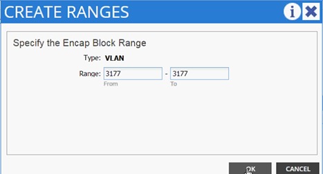
31. Click OK.
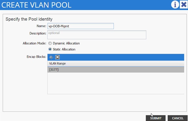
32. Click SUBMIT to finish VLAN pool creation.
33. Click SUBMIT to finish Layer 2 Domain creation.
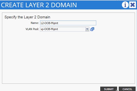
34. Click UPDATE to finish adding Layer 2 domain to AEP.
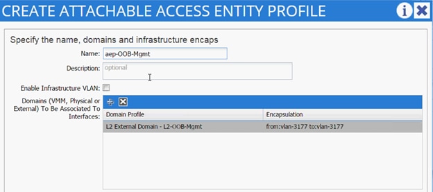
35. Click SUBMIT to finish adding AEP.
36. Click SUBMIT to finish creating vPC Interface Policy Group.
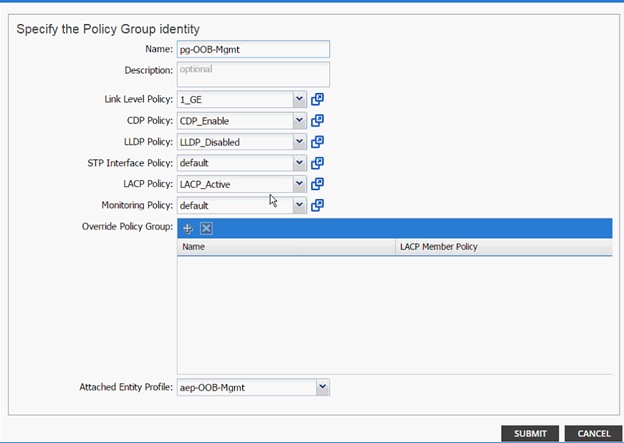
37. On the Configure Interface, PC, vPC screen, click SAVE.
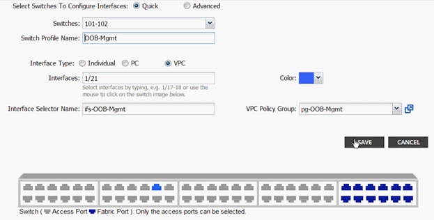
38. Click SAVE.
39. Click SUBMIT to finish the vPC creation.
Configuring the Management Switch
The management switch configuration is covered below. Management switch connects to both Leaf switches using port Gig0/37 and Gig 0/38. These ports form a LACP port-channel Po1.
interface Port-channel1
description *** To ACI Fabric for Common Segment Connectivity ***
switchport trunk encapsulation dot1q
switchport trunk allowed vlan 3177
switchport mode trunk
end
!
interface GigabitEthernet0/37
switchport trunk encapsulation dot1q
switchport trunk allowed vlan 3177
switchport mode trunk
channel-group 1 mode active
end
!
interface GigabitEthernet0/38
switchport trunk encapsulation dot1q
switchport trunk allowed vlan 3177
switchport mode trunk
channel-group 1 mode active
end
!
MGMTSW# show etherchannel summary
Flags: D - down P - in port-channel
I - stand-alone s - suspended
H - Hot-standby (LACP only)
R - Layer3 S - Layer2
U - in use f - failed to allocate aggregator
u - unsuitable for bundling
w - waiting to be aggregated
d - default port
Number of channel-groups in use: 1
Number of aggregators: 1
Group Port-channel Protocol Ports
------+-------------+-----------+-----------------------------------------------
1 Po1(SU) LACP Gi0/37(P) Gi0/38(P)
Configuring Common Tenant
An EPG and a contract is configured in the common tenant. This Contract will be consumed in the all the application tenants, which require access to common services.
Common Management - Application Profile Creation
1. Select Tenant and common tenant from the top menu.
2. Expand Tenant common in the left menu bar.
3. Right-click Application Profile and click Create Application Profile.
4. In the CREATE APPLICATION PROFILE dialog box, enter Management for the Name.
5. From the drop-down menu, select default for Monitoring Policy.
6. Click + next to EPG to add an EPG.
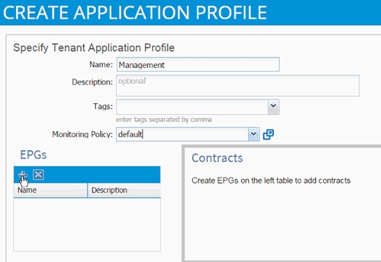
7. In the CREATE APPLICATION EPG dialog box, enter Mgmt_Access for the Name.
8. From the drop-down menu, select Create Bridge Domain as the Bridge Domain.
9. In the CREATE BRIDGE DOMAIN dialog box, use bd-Internal as the Name of the bridge domain.
10. From the drop-down menu next to Network, select Create Private Network.
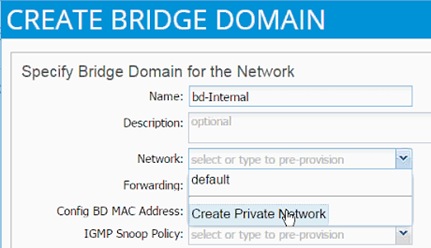
11. In the CREATE PRIVATE NETWORK dialog box, enter Common-Mgmt for the Name.
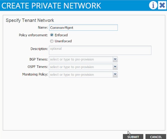
12. Click SUBMIT.
13. Drop down the menu next to Forwarding and select Custom.
14. Check the boxes to enable Flooding and Unicast Routing.
15. Select default for IGMP Snoop Policy.
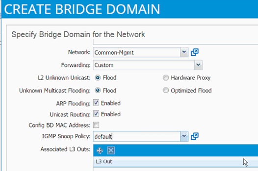
16. Click SUBMIT to finish bridge domain creation.
17. Back in the CREATE APPLICATION EPG dialog box, select the newly created bridge domain.
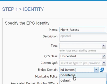
18. From the drop-down menu, select default for Monitoring Policy.
19. Click OK to finish EPG creation.
20. Click SUBMIT to finish creating Application Profile.
21. Expand the newly created Management Application profile from the menu bar on the left.
22. Expand Management, expand Application EPGs and expand EPG Mgmt_Access.
23. Click Static Bindings (Paths).
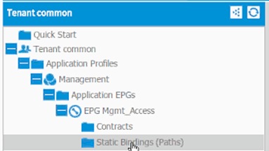
24. Click Action on the right hand work area.
25. Click Deploy Static EPG on PC, vPC, or Interface.
26. In the DEPLOY STATIC EPG ON PC, vPC OR INTERFACE dialog box, select Virtual Port Channel as the Path Type.
27. From the drop-down menu Path, select OUT OF BAND management switch VPC.
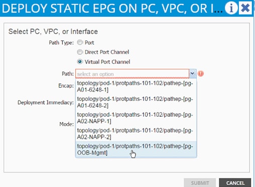
28. Enter vlan-< common_mgmt_segment> for Encap (VLAN 3177 is the common management segment VLAN in the screen capture below).
29. Change Deployment Immediacy to Immediate.
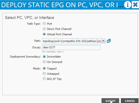
30. Click SUBMIT.
31. On the left hand menu bar, click on Subnet.
32. From the right ACTIONS menu, select Create EPG Subnet.
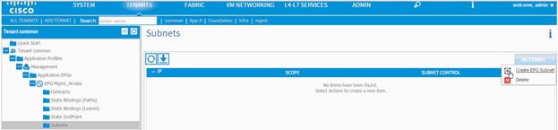
33. In the CREATE EPG SUBNET dialog box, enter 192.168.3.253/24 for the Default Gateway IP. The Mask filed should be auto populated with 255.255.255.0.
34. From the scope, select only Shared Subnet.
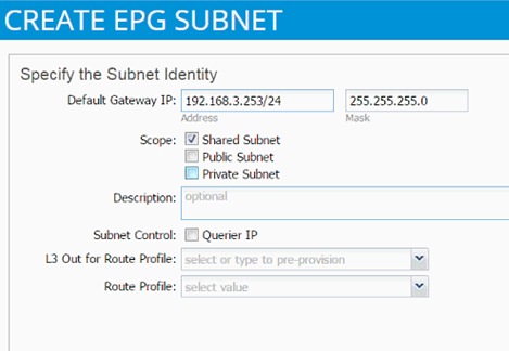
35. Click SUBMIT.
36. Click Contracts under the EPG Mgmt_Access.
37. Click Action and select Add Provided Contract.
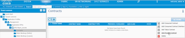
38. From the ADD PROVIDED CONTRACT dialog box, select Create Contract under Contract.
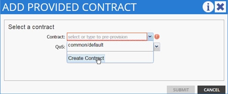
39. Enter Common-Mgmt as Name in the CREATE CONTRACT dialog box.
40. Change the Scope to global from the drop-down menu.
41. Click + next to Subjects to add a new contract subject.
42. In the CREATE CONTRACT SUBJECT dialog box, enter Allow-All as the Name.
43. Click + under Filter Chain to add a new filter.

44. Drop down the menu under FILTERS and click +.
45. In the CREATE FILTER dialog box, enter Allow-All as the Name. In this example, we will allow all the traffic for this contract.
46. Click + to add a filter.
47. Enter Allow-All as the name of the filter.
48. From drop-down menu, select IP as Ethertype.

49. Click Update.
50. Click SUBMIT to create the filter.
51. Click UPDATE to add the newly created filter to the filter chain.
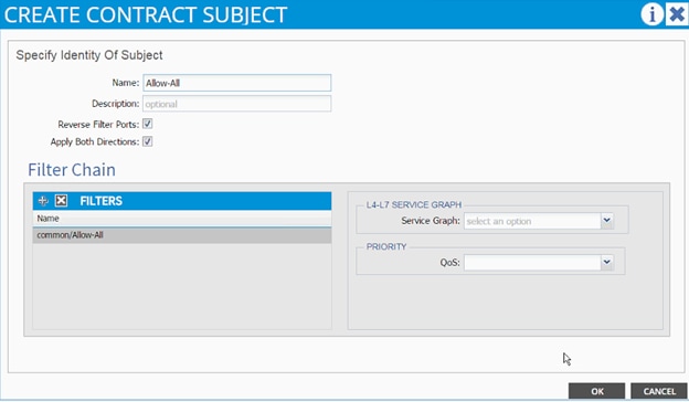
52. Click OK to finish creating the Contract Subject.
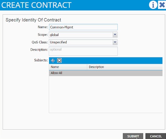
53. Click SUBMIT.
54. Click SUBMIT again to finish adding a provided contract.
55. To validate access to the EPG gateway just added, ping 192.168.3.253 from a common services VM. The VM should be able to ping the address.
Consuming the Common Contract in Application EPGs
1. Select Tenant and App-A tenant from the top menu.
2. Expand Tenant App-A in the left menu bar.
3. Expand the Application Profiles, 3-Tier-App, Application EPGs and EPG Web.
4. Click Contracts.
5. Click ACTIONS and select Add Consumed Contract.
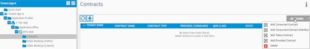
6. In the ADD CONSUMED CONTRACT dialog box, from the drop-down menu select Common/Common-Mgmt contract.
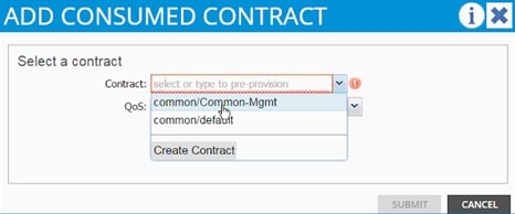
7. Click SUBMIT.
8. To validate the contract definition, click on Application EPGs under Application Profile NFS in the left menu bar.
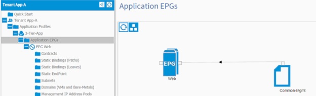
9. Repeat above steps for all the application tiers that need access to the common services.
10. For a Web VM with shown Network Parameters, communication to the 192.168.3.0 subnet should be established and ping should work from 10.1.1.1 to 192.168.3.11.
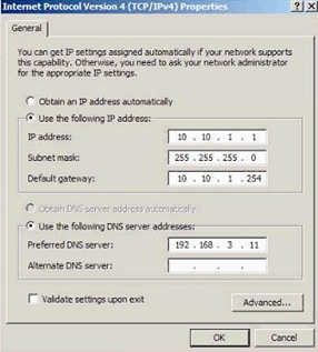
![]() Note: Make sure the common services VMs either use 192.168.3.253 as their default gateway or have a persistent route added for the 10.10.1.0/24 subnet with the gateway set as 192.168.3.253.
Note: Make sure the common services VMs either use 192.168.3.253 as their default gateway or have a persistent route added for the 10.10.1.0/24 subnet with the gateway set as 192.168.3.253.
When configuring NetApp SnapManager and SnapDrive, access to SVM management LIF is required. This configuration can be enabled on a per tenant (per application) basis. A new application profile called SVM-Access is defined under the application tenant (App-A) and an EPG (svm-mgmt) is statically mapped to SVM management LIF VLAN. Access to the svm-mgmt from various application tiers (EPGs) is then enabled using contracts. The contracts are provided by the EPG svm-mgmt and consumed but the application EPGs such as Web and App as defined in the previous sections.
SVM-Access - Application Profile Creation
In this section, a bridge domain will be created and an Application Profile to setup SVM management interface connectivity between the application VMs the SVM management LIF. Since all the LIFs sharing the same uplink port-channel share the same MAC address, a unique bridge domain is required for SVM access.
To create a bridge domain, complete the following steps:
1. Select Tenant and App-A tenant from the top menu.
2. Expand Tenant App-A in the left menu bar.
3. Expand Networking, right click Bridge Domains and select Create Bridge Domain.
4. Use bd-svm-mgmt as Name of the bridge domain.
5. Select App-A from the drop-down menu as the Network.
6. Select Custom from the drop-down menu for Forwarding and enable Flood and ARP Flooding.
7. Select default as the IGMP Snoop Policy.
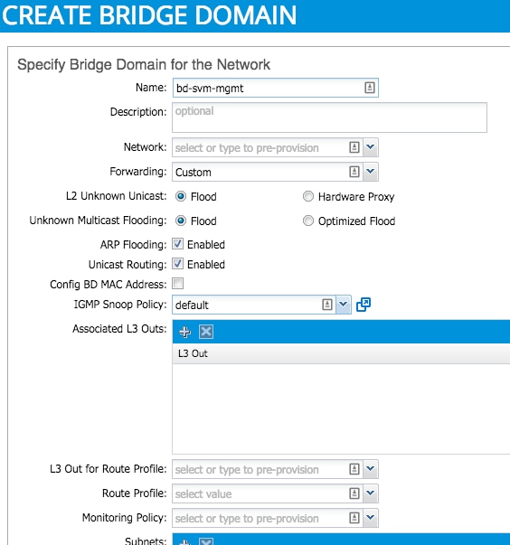
8. Click SUBMIT.
9. In the menu on the left, right click Application Profile and click Create Application Profile.
10. In the CREATE APPLICATION PROFILE dialog box, enter SVM-Access as the Name.
11. From the drop-down menu, select default for Monitoring Policy.
12. Click + next to EPG to add an EPG.
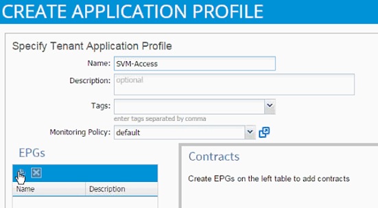
13. In the CREATE APPLICATION EPG dialog box, enter svm-mgmt as the Name.
14. From the drop-down menu, select bd-svm-mgmt as the Bridge Domain.
15. From the drop-down menu, select default for Monitoring Policy.
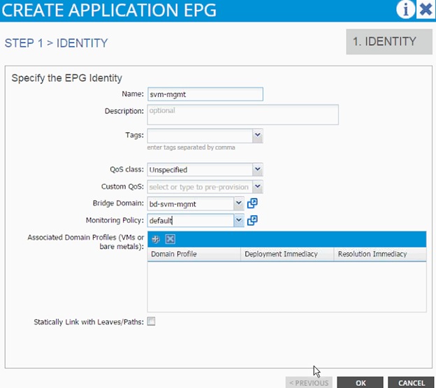
16. Click OK.
17. Click SUBMIT to finish creating Application Profile.
Modifying Physical Domain
A Physical domain associated with NetApp storage needs to be modified and the SVM Management LIF VLAN associated with App-A SVM needs to be added to the physical domain. To modify the physical domain, complete the following steps:
1. Select Fabric and Access Policies from the top menu.
2. Expand Pools and then VLAN.
3. Click the pool name associated with NetApp controllers (vp-A01-NetApp in this example) and click + to add another Encap Block.
4. Enter <<var_svm_mgmt_vlan_tenant>> (a range of 3181 to 3181 in this document) for SVM Management LIF VLAN.
5. Click SUBMIT.
EPG and Contract Configuration
To configure EPG and the contract, complete the following steps:
1. Select Tenant and then App-A from the top menu.
2. Expand the newly created SVM-Access Application profile from the menu bar on the left.
3. Expand SVM-Access, expand Application EPGs and expand EPG svm-mgmt.
4. Click Static Bindings (Paths).
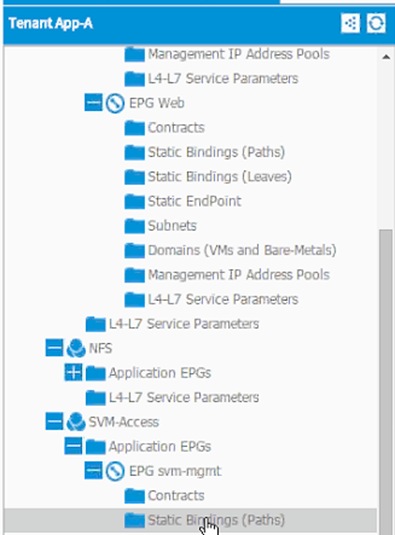
5. Click Action on the right hand work area.
6. Click Deploy Static EPG on PC, vPC, or Interface.
7. In the DEPLOY STATIC EPG ON PC, vPC OR INTERFACE dialog box, select Virtual Port Channel as the Path Type.
8. From the drop-down menu Path, select NetApp Controller 1.

9. Enter vlan-< var_svm_mgmt_vlan_tenant > for Encap (VLAN 3181 is the Mgmt VLAN on NetApp Controller in the screen capture below).
10. Change Deployment Immediacy to Immediate.
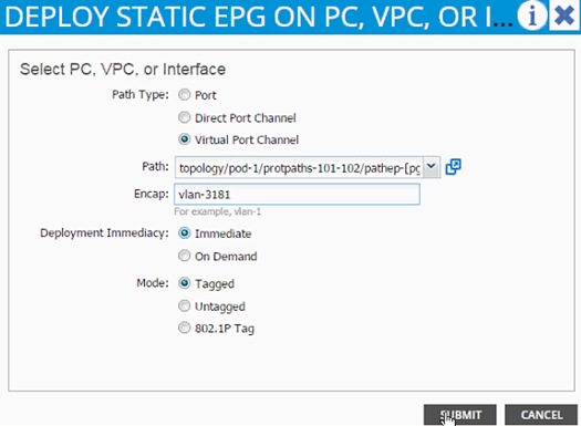
11. Click Submit.
12. Repeat these steps for mapping NetApp Controller 2 path.
13. Click Subnet under the EPG svm-mgmt.
14. Click Contracts under the EPG svm-mgmt.
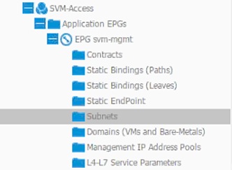
15. Click the Action menu on the right and select Create EPG Subnet.
16. Enter 192.168.181.254/24 for the Default Gateway IP. This IP address is the gateway that SVM management LIF will use.
17. Change scope to only Private Subnet.
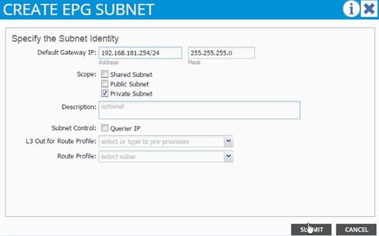
18. Click SUBMIT.
19. Click Action and select Add Provided Contract.
20. From the ADD PROVIDED CONTRACT dialog box, select Create Contract under Contract.

21. Enter Allow-SVM-Access as Name in the CREATE CONTRACT dialog box.
22. Click + next to Subjects to add a new contract subject.
23. In the CREATE CONTRACT SUBJECT dialog box, enter Allow-All as the Name.
24. Click + under Filter Chain to add a new filter.

25. Drop down the menu under FILTERS and select Allow-All filter under Tenant App-A.
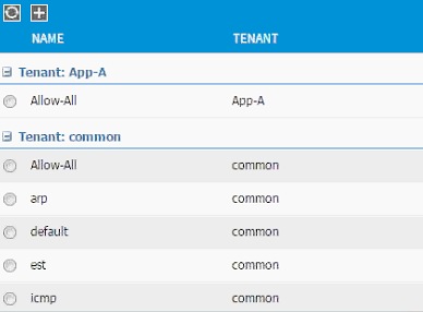
26. Click UPDATE to add the newly created filter to the filter chain.
27. Click OK to finish creating the Contract Subject.
28. Click SUBMIT.
29. Click SUBMIT to finish adding a provided contract.
Consuming the SVM Management Contract in an Application Tier (Web)
1. Expand Application Profile 3-Tier-App.
2. Expand Application EPGs.
3. Expand EPG Web.
4. Click Contracts in the left menu.
5. Click ACTIONS on the right and select Add Consumed Contract.
6. In the ADD CONSUMED CONTRACT dialog box, from the drop-down menu select App-A/Allow-SVM-Access contract (defined previously).
7. Click SUBMIT.
This section provides a detailed procedure for a tenant (App-A) to existing Nexus 7000 core routers using sub-interfaces and VRF aware OSPF. Following are some of the highlights of this connectivity:
· A new bridge domain and associated private network is configured in ACI for external connectivity
· The Web VM is configured with two interfaces – one to connect to an EPG attached to inside bridge domain (bd-internal) and another to connect to an EPG on the external bridge domain (bd-external)*
· Each of the two Nexus 7000s is connected to each of Nexus 9000 leaf
· Sub-interfaces are configured and used for external connectivity
· Nexus 9000 is configured to run per-VRF OSPF – Nexus 7000 does not use VRFs
· Nexus 7000 is configured to originate and send a default route to Nexus 9000 leaves
Figure 6 shows the VLANs and networks used for this connectivity.
![]() Note: When using service graphs (load balancer), the Web-VM does not need two separate interfaces.
Note: When using service graphs (load balancer), the Web-VM does not need two separate interfaces.
Figure 6 ACI – Layer-3 Connectivity Details
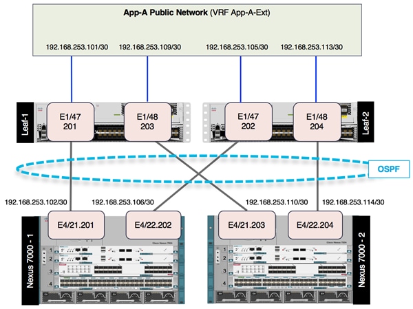
Configuring the Nexus 7000 for ACI Connectivity (Sample)
Nexus 7000-1
feature ospf
!
router ospf 10
router-id 192.168.254.3
area 0.0.0.10 nssa no-summary default-information-originate no-redistribution
!
interface Vlan100
no shutdown
mtu 9216
no ip redirects
ip address 192.168.253.253/30
no ipv6 redirects
ip ospf mtu-ignore
ip router ospf 10 area 0.0.0.0
!
interface Ethernet4/21.201
encapsulation dot1q 201
ip address 192.168.253.102/30
ip ospf mtu-ignore
ip router ospf 10 area 0.0.0.10
no shutdown
!
interface Ethernet4/22.202
encapsulation dot1q 202
ip address 192.168.253.106/30
ip ospf cost 5
ip ospf mtu-ignore
ip router ospf 10 area 0.0.0.10
no shutdown
!
Nexus 7000-2
feature ospf
!
router ospf 10
router-id 192.168.254.4
area 0.0.0.10 nssa no-summary default-information-originate no-redistribution
!
interface Vlan100
no shutdown
mtu 9216
no ip redirects
ip address 192.168.253.254/30
no ipv6 redirects
ip ospf mtu-ignore
ip router ospf 10 area 0.0.0.0
!
interface Ethernet4/21.203
encapsulation dot1q 203
ip address 192.168.253.110/30
ip ospf cost 20
ip ospf mtu-ignore
ip router ospf 10 area 0.0.0.10
no shutdown
!
interface Ethernet4/22.204
encapsulation dot1q 204
ip address 192.168.253.114/30
ip ospf cost 30
ip ospf mtu-ignore
ip router ospf 10 area 0.0.0.10
no shutdown
!
Configuring ACI for External Routed Domain
1. Select Tenant and App-A tenant from the top menu.
2. Expand Tenant App-A in the left menu bar.
3. Expand Networking, right click Bridge Domains and select Create Bridge Domain.
4. Use bd-external as Name of the bridge domain.
5. From the drop-down menu next to Network, select Create Private Network.
6. In the CREATE PRIVATE NETWORK dialog box, enter App-A-Ext for the Name.
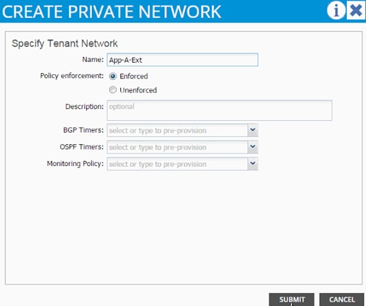
7. Click SUBMIT.
8. Select default as the IGMP Snoop Policy.
9. Click + next to Subnets to add a subnet.
10. Provide the gateway address of the subnet which will communicate to the external world.
11. Set Scope as Public.
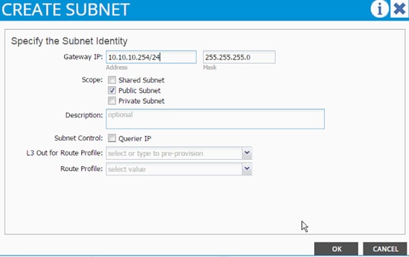
12. Click OK.
13. Click SUBMIT.
14. Expand the Application Profile 3-Tier-App on the left and right click on Application EPGs and click Create Application EPG.
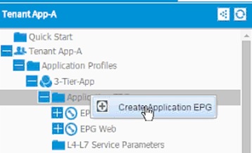
15. In the CREATE APPLICATION EPG dialog box, enter External as the Name.
16. From the drop-down menu, select bd-External as the Bridge Domain.
17. From the drop-down menu, select default for Monitoring Policy.
18. Click OK.
19. Click + next to Associated Domain Profiles (VMs or Bare metals).
20. From the drop-down menu, select the VMM domain previously defined.
21. Select Immediate for Deployment Immediacy.
22. Select Immediate for Resolution Immediacy.
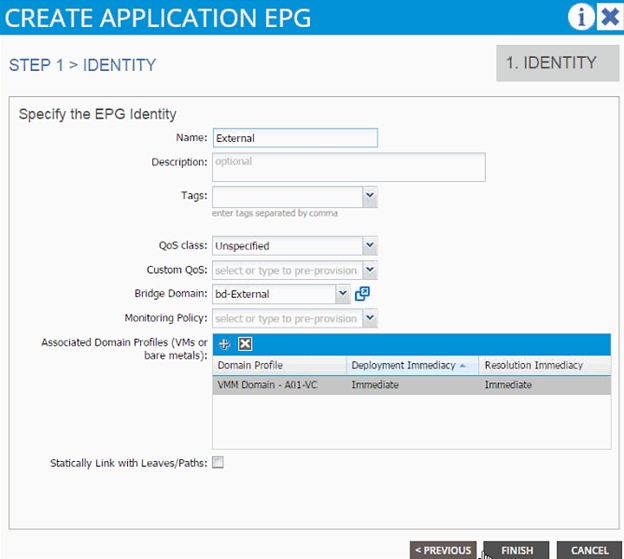
23. Click FINISH.
24. On the left menu, expand the EPG External and click Contracts.
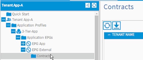
25. Click Action and select Add Provided Contract.
26. From the ADD PROVIDED CONTRACT dialog box, select Create Contract under Contract.
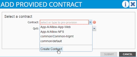
27. Enter Allow-External as Name in the CREATE CONTRACT dialog box.
28. Change the Scope to Tenant.
29. Click + next to Subjects to add a new contract subject.
30. In the CREATE CONTRACT SUBJECT dialog box, enter Allow-All as the Name.
31. Click + under Filter Chain to add a new filter.
32. Drop down the menu under FILTERS and select Allow-All filter under Tenant App-A.
33. Click UPDATE to add the newly created filter to the filter chain.
34. Click OK to finish creating the Contract Subject.
35. Click SUBMIT.
36. Click SUBMIT again to finish adding a provided contract.
Adding External Routed Domain
1. Select Tenants and App-A from the top menu.
2. Expand Tenant App-A in the left menu.
3. Expand Networking and External Routed Networks.
4. Right-clickExternal Routed Networks and select Create Routed Outside.
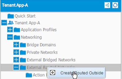
5. In the CREATE ROUTED OUTSIDE dialog box, enter App-A-L3-Out as the Name.
6. Click the check mark next to OSPF.
7. Enter 0.0.0.10 as the OSPF Area ID.
8. Select App-A-Ext from the drop-down menu as the Private Network.
9. Click + next to NODES AND INTERFACES PROTOCOL PROFILES.
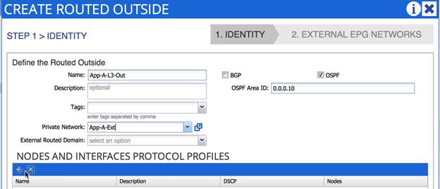
10. In the CREATE NODE PROFILE dialog box, enter Node_101 as the Name.
11. Click + to add Nodes.
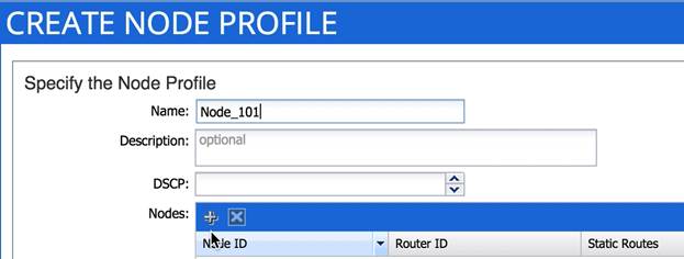
12. In the SELECT NODE dialog box, select first Nexus 9000 switch (Node-101).
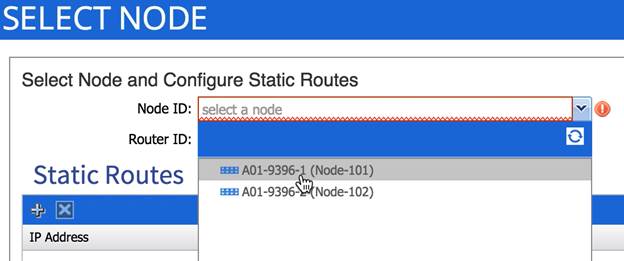
13. Provide a loopback address to be used for the tenant private network.
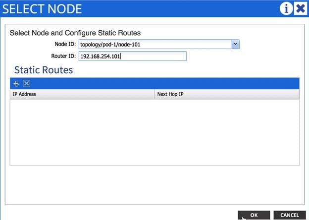
14. Click OK.
15. Click + to add OSPF INTERFACE PROFILE.
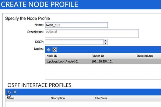
16. In the CREATE INTERFACE PROFILE dialog box, use a descriptive name (Node101_Int_Profile in this example provides information about interface policy for Node 101).
17. Drop down the OSPF Policy menu and select Create OSPF Interface Policy.
18. In the CREATE OSPF INTERFACE POLICY dialog box, provide a descriptive name.
19. Check MTU ignore and Advertise Subnet.
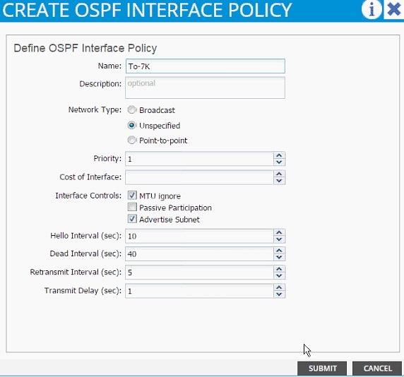
20. Click SUBMIT.
21. Under INTERFACES, select ROUTED SUB-INTERFACE and click + to add a new sub-interface.
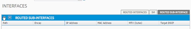
22. In the SELECT ROUTED SUB-INTERFACE dialog box, select the Nexus 9000-1 interface connected to Nexus 7000-1 (Eth 1/47).
23. In the Encap enter vlan-201.
24. Provide the IP address 192.168.253.101/30.
25. Set MTU to 1500.
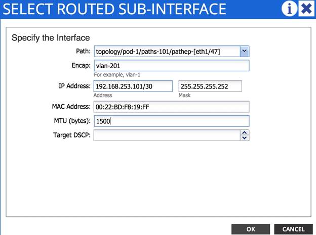
26. Click OK.
27. Repeat steps 21-26 to add a second interface profile with appropriate sub-interfaces. The OSPF Policy created in steps 18-20 can be re-used (select from the drop-down list) for the interface profiles.
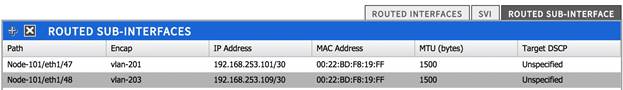
28. Click OK.
29. Click + next to NODES AND INTERFACES PROTOCOL PROFILES.

30. In the CREATE NODE PROFILE dialog box, enter Node_102 as the Name.
31. Click + to add Nodes.
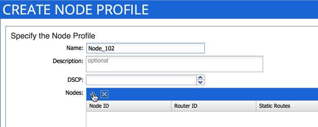
32. In the SELECT NODE dialog box, select second Nexus 9000 switch (Node-102).
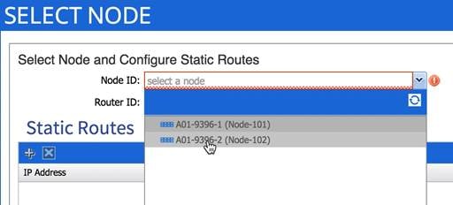
33. Provide a loopback address to be used for the tenant private network.
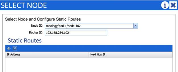
34. Click OK.
35. Click + to add OSPF INTERFACE PROFILE.
36. In the CREATE INTERFACE PROFILE dialog box, use a descriptive name (Node102_Int_Profile in this example provides information about interface policy for Node 101).
37. Drop down the OSPF Policy menu and select previously created OSPF policy.
38. Click SUBMIT.
39. Under INTERFACES, select ROUTED SUB-INTERFACE and click + to add a new sub-interface.
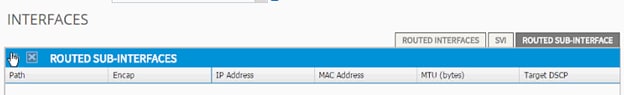
40. In the SELECT ROUTED SUB-INTERFACE dialog box, select the Nexus 9000-2 interface connected to Nexus 7000-1 (Eth 1/47).
41. In the Encap enter vlan-202.
42. Provide the IP address.
43. Set MTU to 1500.
44. Click OK.
45. Repeat these steps to add second interface profiles with appropriate sub-interfaces.
46. Click OK.
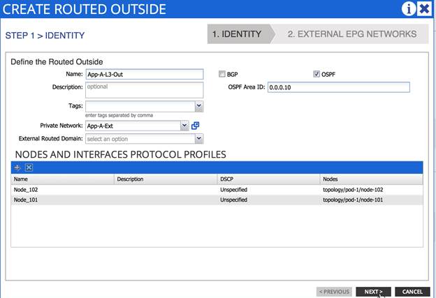
47. Click Next.
48. Click + to add EXTERNAL EPG NETWORKS.
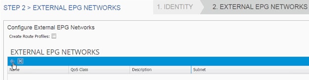
49. In the CREATE EXTERNAL NETWORK dialog box, enter Ext-Default as the Name.
50. Click + next to SUBNET to add remote subnet that will be accessed from the ACI fabric.
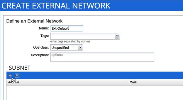
51. In the CREATE SUBNET dialog box, enter 0.0.0.0/0 as the remote subnet to be accessed.
52. Click OK.
53. Click OK.
54. Click FINISH.
55. Expand the App-A-L3-Out routed network and click on the newly created network Ext-Default.
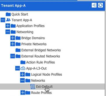
56. On the right hand side, click + next to Consumed Contracts.
57. From the drop-down menu, select App-A/Allow-External contract.
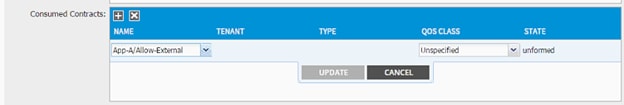
58. Click UPDATE.
59. Click SUBMIT.
60. Expand Bridge Domains in the menu on the left.
61. Click bd-External and click + next to Associated L3 Outs.
62. From the drop-down menu, select the newly created routed domain App-A/App-A-L3-Out.
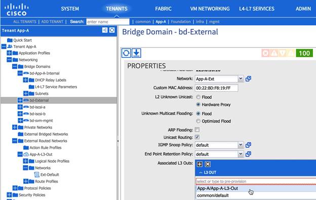
63. Click UPDATE.
64. Click SUBMIT.
At this time, the network, 10.10.10.0/24, marked public under bridge domain bd-External should be visible in the Nexus 7000 routing table and Nexus 9000 should learn the OSPF routes including default route from Nexus 7000. The provider and consumed contracts should enable communication from a VM connected to External EPG (port-group) and any subnet on the external network.
Configuring Multi-Protocol BGP on Spines
Within the ACI fabric, Multiprotocol BGP (MP-BGP) is implemented between leaf and spine switches to propagate external routes within the ACI fabric. The BGP route reflector technology is deployed in order to support a large number of leaf switches within a single fabric. All of the leaf and spine switches are in one single BGP autonomous system (AS). When the border leaf learns the external routes, it can then redistribute the external routes of a given VRF to an MP-BGP address family VPN version 4 (or VPN version 6 when IPv6 routing is supported in ACI). With address family VPN version 4, MP-BGP maintains a separate BGP routing table for each VRF. Within MP-BGP, the border leaf advertises routes to a spine switch, which is a BGP route reflector.
MP-BGP is not enabled by default in the ACI fabric. For the deployment scenario where ACI fabric is used as L2 fabric or there is no need for L3 outside connection, MP-BGP is not required. To enable MP-BGP please configure BGP policy on the APIC to specify the BGP ASN and specify spine nodes as BGP route reflectors.
1. Select Fabric and Fabric Policies from the top menu.
2. Expand Pod Policies and Policies in the left menu bar.
3. Click BGP Route Reflector default.
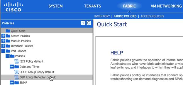
4. Enter an Autonomous System Number (100 in this example).
5. Click + to select spines (one after the other) as Route Reflector Nodes.
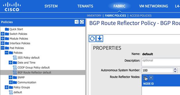
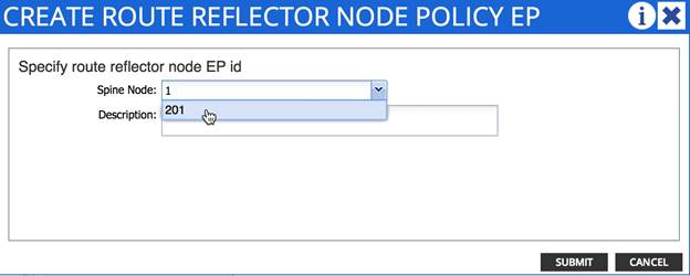
6. Click SUBMIT.
7. Right-click Policy Groups in left menu bar and select Create POD Policy Group.
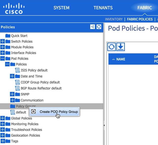
8. Enter a descriptive name for Pod1 policy.
9. From the drop-down menu BGP Route Reflector Policy, select default.
![]() Note: The policy group allows users to combine multiple policies, such as BGP policy, Integrated System to Integrated System (IS-IS) routing protocol policy, co-operative (COOP) policy, and others, to a policy group and apply it to the POD. In this example, the policy is being utilized to only make changes to BGP.
Note: The policy group allows users to combine multiple policies, such as BGP policy, Integrated System to Integrated System (IS-IS) routing protocol policy, co-operative (COOP) policy, and others, to a policy group and apply it to the POD. In this example, the policy is being utilized to only make changes to BGP.
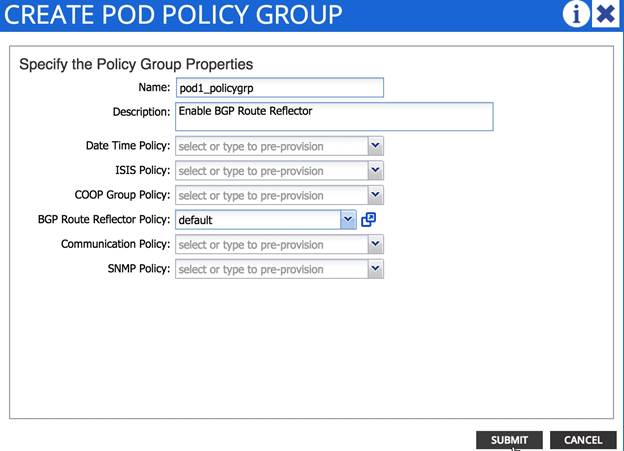
10. Click SUBMIT.
11. Click default from Policy in the left menu bar.
12. From the drop-down menu Fabric Policy Group, select the recently created Pod policy (pod1_policygrp in this example).
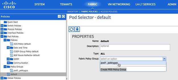
13. Click SUBMIT.
NetApp Virtual Storage Console (VSC) 6.0 Deployment Procedure
This section describes the deployment procedures for the NetApp Virtual Storage Console (VSC).
VSC 6.0 Pre-installation Considerations
The following licenses are required for VSC on storage systems that run clustered Data ONTAP 8.3:
· Protocol licenses (NFS and FCP)
· FlexClone (for provisioning and cloning only)
· SnapRestore (for backup and recovery)
· SnapManager suite
Install VSC 6.0
To install the VSC 6.0 software, complete the following steps:
1. Build a VSC virtual machine with Windows Server 2012 R2, 4GB RAM, two CPUs, and one virtual network interface in the <<var_ib_mgmt_vlan_id>> VLAN. The virtual network interface should be a VMXNET 3 adapter.
2. Bring up the VM, install VMware Tools, assign IP addresses, and join the machine to the Active Directory domain.
3. Activate Adobe Flash Player in Windows Server 2012 R2 by installing Desktop Experience under the User Interfaces and Infrastructure Feature on the VM.
4. Install all Windows updates on the VM.
5. Log in to the VSC VM as FlexPod admin user.
6. Download the x64 version of the Virtual Storage Console 6.0 from the NetApp Support site.
7. From the VMware Console, right-click the VSC-6.0-win64.exe file downloaded in step 3 and select Run as administrator.
8. Select the appropriate language and click OK.
9. On the Installation wizard Welcome page, click Next.
10. Select the checkbox to accept the message, click Next.
11. Select the Backup and Recovery capability. Click Next.
![]() Note: The Backup and Recovery capability requires an additional license.
Note: The Backup and Recovery capability requires an additional license.
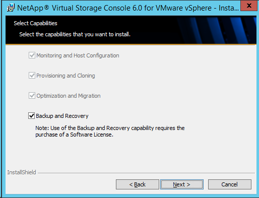
12. Click Next to accept the default installation location.
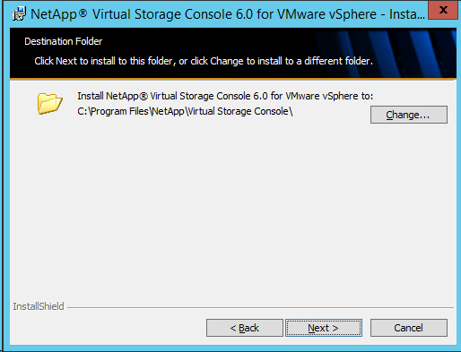
13. Click Install.
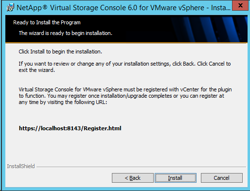
14. Click Finish.
Register VSC with vCenter Server
To register the VSC with the vCenter Server, complete the following steps:
1. A browser window with the registration URL opens automatically when the installation phase is complete. If the URL does not open automatically, open https://localhost:8143/Register.html in Internet Explorer.
2. Click Continue to this website (not recommended).
3. In the Plug-in Service Information section, select the local IP address that the vCenter Server uses to access the VSC server from the drop-down list.
4. In the vCenter Server Information section, enter the host name or IP address, user name (FlexPod admin user or root), and user password for the vCenter Server. Click Register to complete the registration.
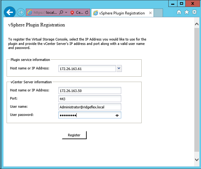
5. Upon successful registration, the storage controllers are discovered automatically.
![]() Note: Storage discovery process will take some time.
Note: Storage discovery process will take some time.
Discover and Add Storage Resources
To discover storage resources for the Monitoring and Host Configuration and the Provisioning and Cloning capabilities, complete the following steps:
1. Using the vSphere web client, log in to the vCenter Server as FlexPod admin user or root. If the vSphere web client was previously opened, close it and then reopen it.
2. In the Home screen, click the Home tab and click Virtual Storage Console.
3. Select Storage Systems. Under the Objects tab, click Actions > Modify.
4. In the IP Address/Hostname field, enter the storage cluster management IP. Enter admin for the user name, and the admin password for password. Confirm that Use SSL to connect to this storage system is selected. Click OK.
5. Click OK to accept the controller privileges.
Optimal Storage Settings for ESXi Hosts
VSC allows for the automated configuration of storage-related settings for all ESXi hosts that are connected to NetApp storage controllers. To use these settings, complete the following steps:
1. From the Home screen, click on vCenter > Hosts and Clusters. For each ESXi host, right-click and select NetApp VSC > Set Recommended Values for these hosts.
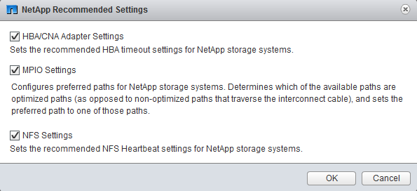
2. Check the settings that are to be applied to the selected vSphere hosts. Click OK to apply the settings.
![]() Note: This functionality sets values for HBAs and CNAs, sets appropriate paths, and path-selection plug-ins, and verifies appropriate settings for software-based I/O (NFS and iSCSI).
Note: This functionality sets values for HBAs and CNAs, sets appropriate paths, and path-selection plug-ins, and verifies appropriate settings for software-based I/O (NFS and iSCSI).
3. Click OK.
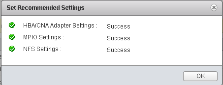
For each host were settings were adjusted in the previous step, place the host in Maintenance Mode, reboot the host, and exit Maintenance Mode.
VSC 6.0 Backup and Recovery
Prerequisites to Use Backup and Recovery Capability
Before you begin using the Backup and Recovery capability to schedule backups and restore your datastores, virtual machines, or virtual disk files, you must confirm that the storage systems that contain the datastores and virtual machines for which you are creating backups have valid storage credentials.
If you plan to leverage the SnapMirror update option, add all the destination storage systems with valid storage credentials.
Backup and Recovery Configuration
The following steps detail the procedure to configure a backup job for a datastore.
1. From Home screen, select the Home tab and click Storage.
2. On the left, expand the Datacenter and select Datastores.
3. Right-click the datastore which you need to backup. Select NetApp VSC > Backup > Schedule Backup Job.
![]() Note: If you prefer a onetime backup, then choose Backup Now instead of Schedule Backup.
Note: If you prefer a onetime backup, then choose Backup Now instead of Schedule Backup.
4. Type a backup job name and description.
![]() Note: If you want to create a VMware snapshot for each backup, select Perform VMware consistency snapshot in the options pane.
Note: If you want to create a VMware snapshot for each backup, select Perform VMware consistency snapshot in the options pane.
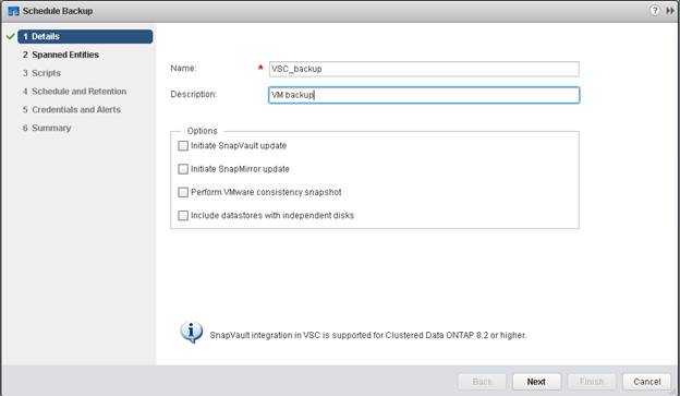
5. Click Next.
6. Click Next.
7. Select one or more backup scripts if available and click Next.
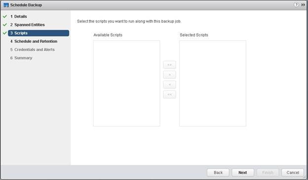
8. Select the hourly, daily, weekly, or monthly schedule that you want for this backup job and click Next.
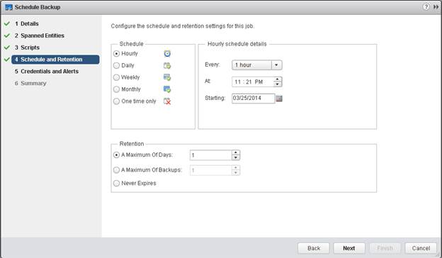
9. Use the default vCenter credentials or type the user name and password for the vCenter Server and click Next.
10. Specify backup retention details as per requirements. Enter an e-mail address for receiving e-mail alerts. You can add multiple e-mail addresses by using semicolons to separate e-mail addresses. Click Next.
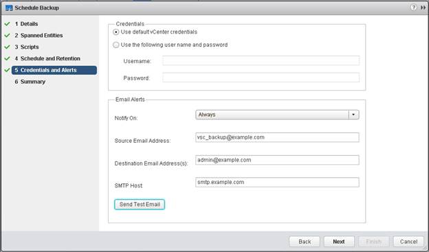
11. Review the summary page and click Finish. If you want to run the job immediately, select the Run Job Now option and then click Finish.
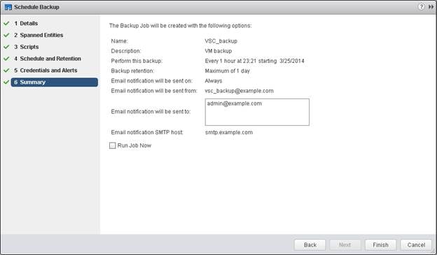
12. Click OK.
13. On the storage cluster interface, automatic Snapshot copies of the volume can be disabled by entering the following command:
volume modify –volume infra_datastore_1 –snapshot-policy none
14. Also, to delete any existing automatic Snapshot copies that have been created on the volume, enter the following command:
volume snapshot show –volume infra_datastore_1
volume snapshot delete –volume infra_datastore_1 –vserver Infra-SVM –snapshot <snapshot name>
![]() Note: The wildcard character, *, can be used in snapshot names in the previous command.
Note: The wildcard character, *, can be used in snapshot names in the previous command.
NetApp VASA Provider for Clustered Data ONTAP Deployment Procedure
VASA Provider for clustered Data ONTAP uses VMware VASA (vSphere APIs for Storage Awareness) to provide better storage management. By providing information about storage used by Virtual Storage Console for VMware vSphere to the vCenter Server, VASA Provider enables you to make more intelligent virtual machine provisioning decisions and allows the vCenter Server to warn you when certain storage conditions may affect your VMware environment. Virtual Storage Console for VMware vSphere is the management console for VASA Provider. Note that DNS must be setup properly for the VASA provider to register with vCenter. The VASA Provider will do a reverse lookup of its provisioned IP address and the hostname from the lookup should match the provisioned hostname. To install the NetApp VASA provider, complete the following steps:
1. Download the VASA Provider 6.0 for Clustered Data ONTAP OVA file from the NetApp support site.
2. Log into the vSphere Web Client. Go to vCenter > VMs and Templates
3. At the top of the center pane, click Actions > Deploy OVF Template.
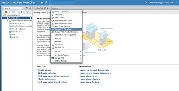
4. Browse the .ova file that was downloaded locally. Click Open to select the file.
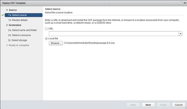
5. Click Next to proceed with the selected file.
6. Click Next.
7. Read the EULA, then click the Accept button to accept the agreement. Click Next to continue.
8. Enter the name of the VM and select the FlexPod_DC_1 folder to hold the VM. Click Next to continue.
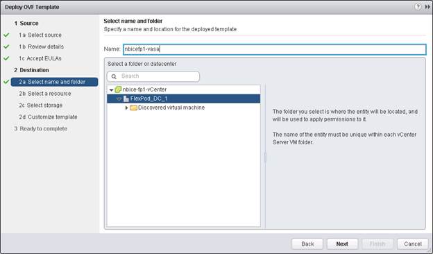
9. Select FlexPod_Management within the FlexPod_DC_1 Datacenter as the destination compute resource pool to host the VM. Click Next to continue.

10. Select infra_datastore_1 as the storage target for the VM and select Thin Provision as the Virtual disk format. Click Next to continue.
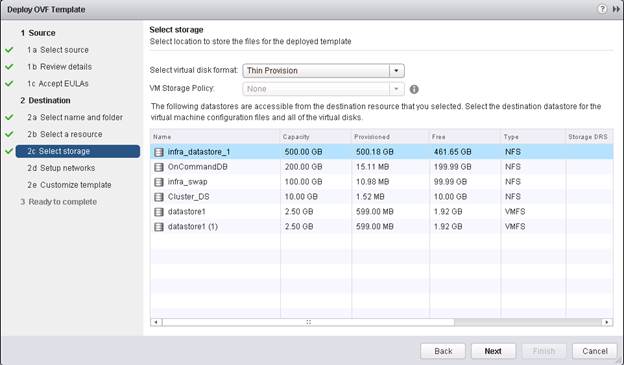
11. Select MGMT Network as the destination network to the nat source network. Click Next.
12. Fill out the details for the Host Name, IP Address, Netmask, gateway, Primary DNS, and Secondary DNS. Click Next to continue.
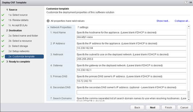
13. Select Power on after deployment and click Finish. Wait for the OVA to deploy.
14. Select the VASA VM and click Open Console or Open with VRMC. VASA Provider installation will prompt for installing the VMware tools.
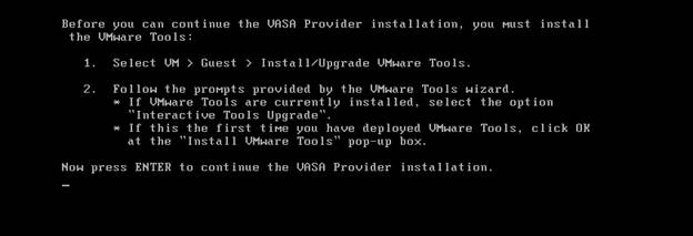
15. In the web client, click on the VASA VM. Click Summary tab.
16. Click Install VMware Tools and switch back to VASA VM console window.
17. In the VASA VM console, press Enter to continue the VASA provider installation and install VMware tools.
18. Press Enter to reboot the VM.
19. Upon reboot, the VASA appliance will prompt for Maint and vpserver passwords. Type the new passwords accordingly. Press Enter to continue. Wait for the VASA Provider to complete startup.
Registering VASA Provider for Clustered Data ONTAP with VSC
1. Log in to the web client. Click Virtual Storage Console.
2. Click Configuration. Click Register/Unregister VASA Vendor Provider.
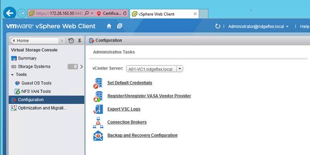
3. Click OK. Enter the IP Address and vpserver Password for the VASA VM. Click Register.
4. Log out of the web client and log back in to view the Vendor Provider user interface.
5. Select Home > Virtual Storage Console.
6. Select VASA Provider for clustered Data ONTAP.
7. Select Storage Mapping.
8. Click the first icon under the Objects tab to Global auto-generate profiles.
9. Click OK, then click OK again.
10. All of the datastores that on located on the AFF should now show SSD in their profile.
11. These profiles can now be used in datastore provisioning.
OnCommand Unified Manager 6.2
OnCommand Unified Manager OVF Deployment
To install the OnCommand Unified Manager, complete the following steps:
Download and review the OnCommand Unified Manager Installation and Setup Guide.
1. Download the OnCommand Unified Manager version 6.2P1 (OnCommandUnifiedManager-6.2P1.ova), from http://mysupport.netapp.com/NOW/download/software/oncommand_cdot/6.2P1/
2. Log in to the vSphere Web Client. Go to vCenter > VMs and Templates.
3. At the top of the center pane, click Actions > Deploy OVF Template.

4. Browse the .ova file that was downloaded locally. Click Open to select the file. Click Next to proceed with the selected file.
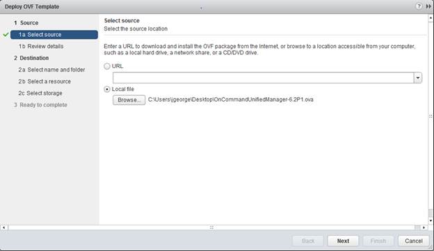
5. Click the checkbox to accept the additional configuration options and click Next.
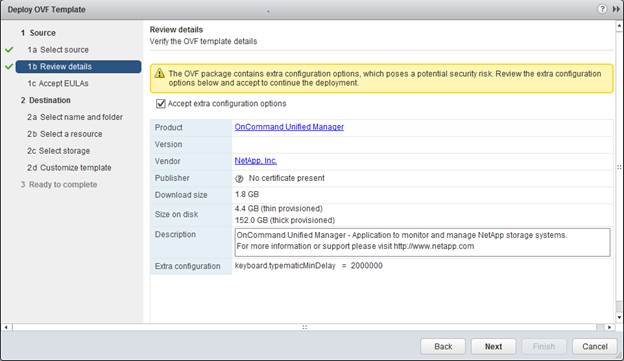
6. Read the EULA, then click the Accept button to accept the agreement. Click Next to continue.
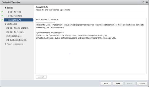
7. Enter the name of the VM and select the FlexPod_DC_1 folder to hold the VM. Click Next to continue.
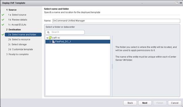
8. Select FlexPod_Management within the FlexPod_DC_1 datacenter as the destination compute resource pool to host the VM. Click Next to continue.
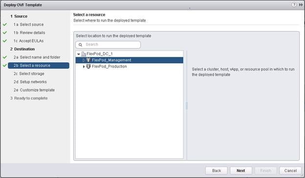
9. Select infra_datastore_1 as the storage target for the VM and select Thin Provision as the Virtual disk format. Click Next to continue.
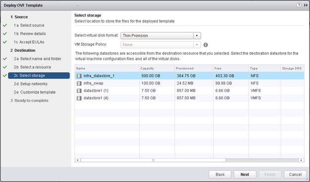
10. Select MGMT Network as the destination network to the nat source network. Click Next.
11. Fill out the details for the Host Name, IP Address, Network Mask, Gateway, Primary DNS, and Secondary DNS. Click Next to continue.
12. Clear the Power on after deployment checkbox.
13. Review the configuration details. Click Finish to begin deploying the VM with the provided configuration details.
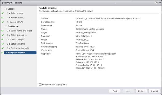
14. On the left pane, navigate to vCenter -> Virtual machines. After OVF deployment is complete, right-click the newly created virtual machine and select Edit Settings.
15. Click the CPU tab to expand the CPU options:
a. The minimum required CPU Reservation is 4786 MHz. Determine the CPU frequency of the host.
b. Set the number of CPUs to the number of CPUs required (4786 / CPU Frequency of host).
c. Set the number of Cores per Socket where the Sockets number on the right matches the number of CPU sockets in the host. For example, if a host has 2 CPUs operating at a speed of 1999MHz, then the VM would need 4 virtual CPUs (4786 / 1999 = 2.39 – rounded to 4 virtual CPUs). If the host has 2 physical CPU sockets, 2 Cores per Socket, set the CPU Reservation and Limit to 4786 MHz
d. The amount of memory can be set to 8 GB. Use the OnCommand Unified Manager Installation and Setup Guide for guidance on these settings.
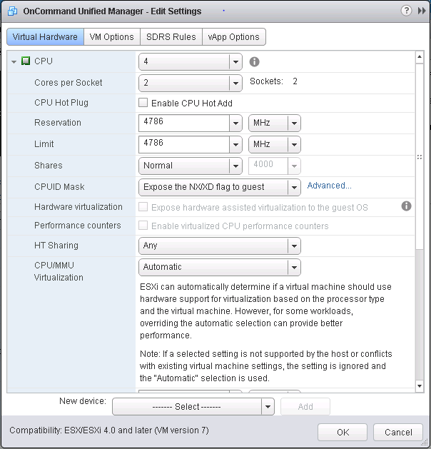
16. Click OK to accept the changes.
17. Right-click the VM in the left-hand pane. Click Power On.
OnCommand Unified Manager Basic Setup
1. Select the VM in the left-hand pane. In the center pane, select Open with VMRC.
2. In the VMRC window, select Manage > Install VMware Tools. VMware Tools will install in the VM.

3. Set up OnCommand Unified Manager by answering the following questions in the console window:
Geographic area: <<Enter your geographic location>>
Time zone: <<Select the city or region corresponding to your time zone>>
These commands complete the network configuration checks SSL certificate generation for HTTPS and start the OnCommand Unified Manager services.
4. To Create a Maintenance User account, run the following commands:
![]() Note: The maintenance user manages and maintains the settings on the OnCommand Unified Manager virtual appliance.
Note: The maintenance user manages and maintains the settings on the OnCommand Unified Manager virtual appliance.
Username : admin
Enter new UNIX password: <<var_password>>
Retype new UNIX password: <<var_password>>
5. Using a web browser navigate to the OnCommand Unified Manager using URL: https:// <<var_oncommand_server_ip>>.
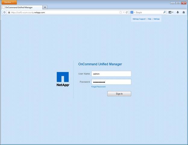
6. Log in using the Maintenance User account credentials.
7. Select Yes option to enable AutoSupport capabilities.
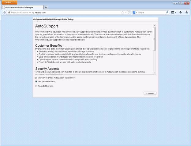
8. Click Continue.
9. Provide the NTP Server IP address <<var_global_ntp_server_ip>>
10. Provide the Maintenance User Email <<var_storage_admin_email>>
11. Provide the SMTP Server Hostname.
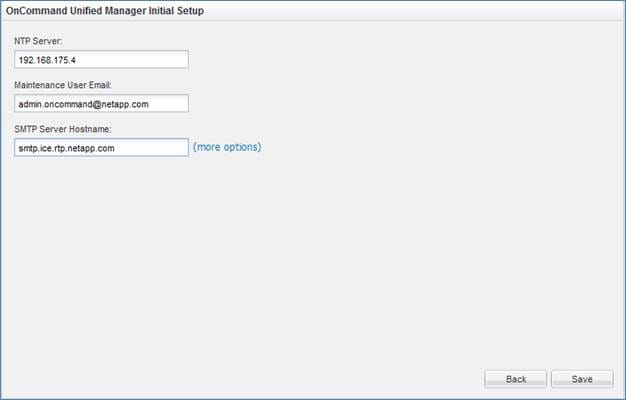
12. Click Save.
13. Click Add Cluster
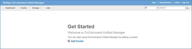
14. Provide the Cluster Management IP address, User Name, Password, Protocol, and Port.
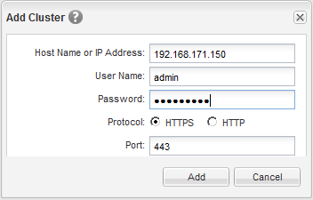
15. Click Add.
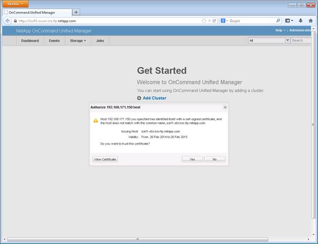
16. Click Yes to trust the certificate from the controller.
![]() Note: The Cluster Add operation might take a couple of minutes.
Note: The Cluster Add operation might take a couple of minutes.
17. After the cluster is added it can be accessed by clicking on the Storage tab and selecting Clusters.
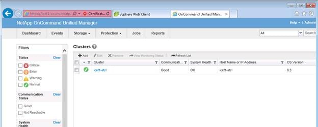
OnCommand Performance Manager 1.1
OnCommand Performance Manager OVF Deployment
To install the OnCommand Performance Manager, complete the following steps:
Download and review the OnCommand Performance Manager 1.1 Installation and Administration Guide for VMware Virtual Appliances.
1. Download the OnCommand Performance Manager version 1.1 (OnCommandPerformanceManager-netapp-1.1.0.ova), from http://mysupport.netapp.com/NOW/download/software/oncommand_pm/1.1/OnCommandPerformanceManager-netapp-1.1.0.ova
2. Log in to the vSphere Web Client. Go to vCenter > VMs and Templates.
3. At the top of the center pane, click Actions > Deploy OVF Template.
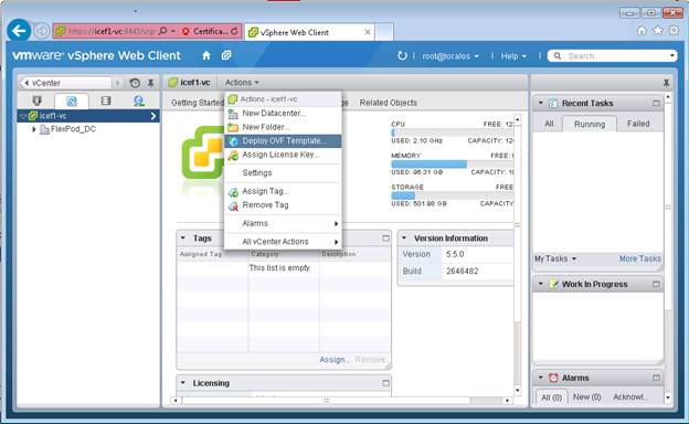
4. Browse the .ova file that was downloaded locally. Click Open to select the file. Click Next to proceed with the selected file.
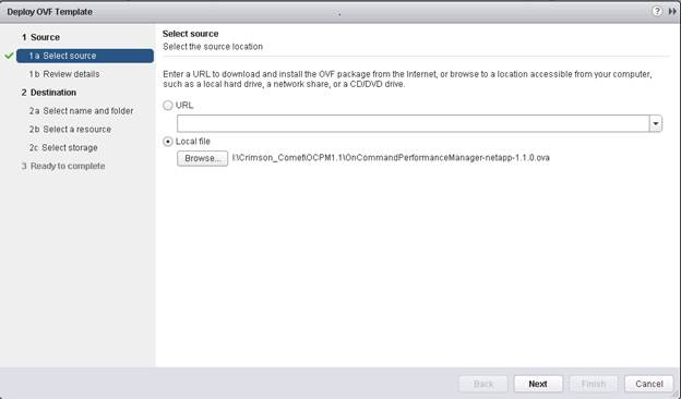
5. Click the checkbox to accept the additional configuration options and click Next.
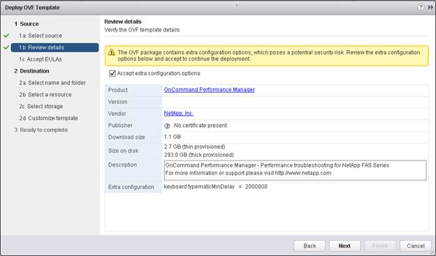
6. Read the EULA, and then click the Accept button to accept the agreement. Click Next to continue.
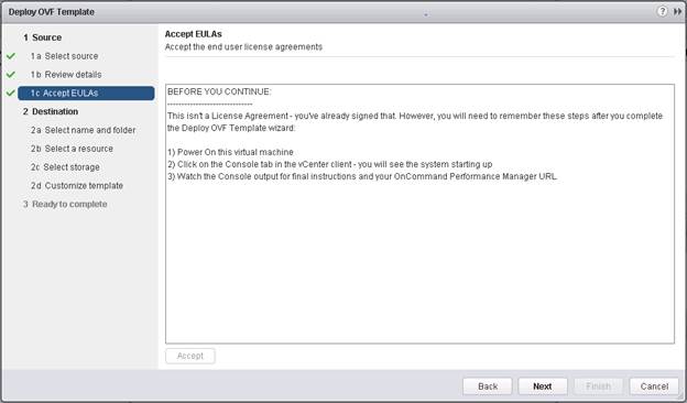
7. Enter the name of the VM and select the FlexPod_DC_1 folder to hold the VM. Click Next to continue.
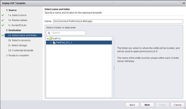
8. Select FlexPod_Management within the FlexPod_DC_1 datacenter as the destination compute resource pool to host the VM. Click Next to continue.

9. Select infra_datastore_1 as the storage target for the VM and select Thin Provision as the Virtual disk format. Click Next to continue.
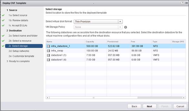
10. Select MGMT Network as the destination network to the nat source network. Click Next.
11. Fill out the details for the Host Name, IP Address, Network Mask, Gateway, Primary DNS, and Secondary DNS. Click Next to continue.
12. Clear the Power on after deployment checkbox.
13. Review the configuration details. Click Finish to begin deploying the VM with the provided configuration details.
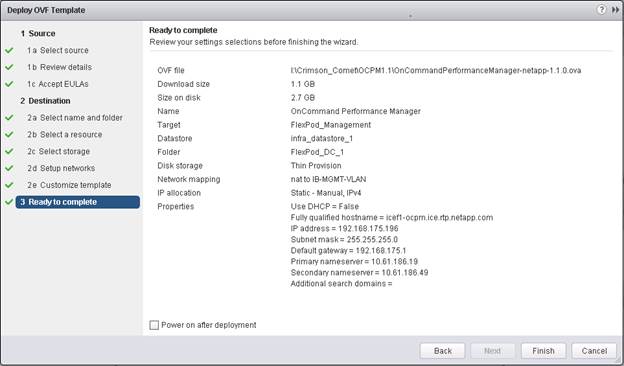
14. On the left pane, navigate to vCenter -> Virtual machines. After OVF deployment is complete, right-click the newly created virtual machine and select Edit Settings.
15. Click the CPU tab to expand the CPU options:
a. The minimum required CPU Reservation is 9572 MHz. Determine the CPU frequency of the host.
b. Set the number of CPUs to the number of CPUs required (9572 / CPU Frequency of host).
c. Set the number of Cores per Socket where the Sockets number on the right matches the number of CPU sockets in the host. For example, if a host has 2 CPUs operating at a speed of 1999MHz, then the VM would need 6 virtual CPUs (9572 / 1999 = 4.79 – rounded to 6 virtual CPUs). If the host has 2 physical CPU sockets, 3 Cores per Socket.
![]() Note: Use the OnCommand Performance Manager 1.1 Installation and Administration Guide for VMware Virtual Appliances for guidance on these settings.
Note: Use the OnCommand Performance Manager 1.1 Installation and Administration Guide for VMware Virtual Appliances for guidance on these settings.
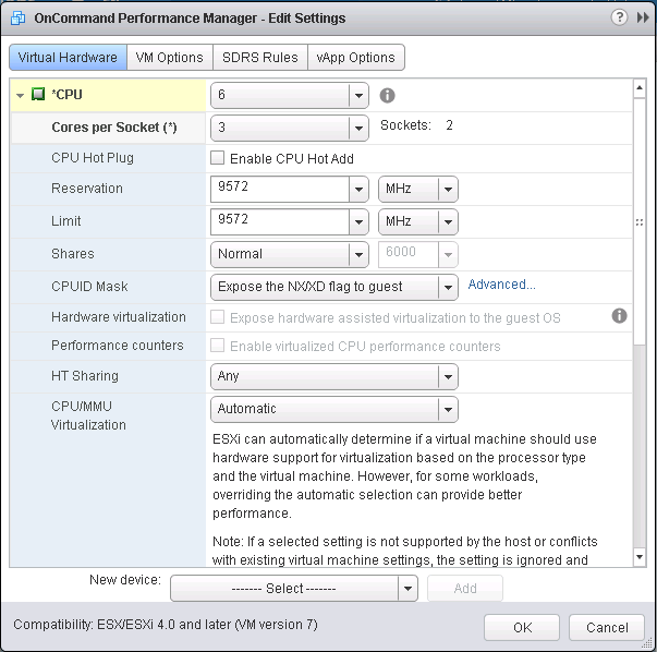
16. Click OK to accept the changes.
17. Right-click the VM in the left-hand pane. Click Power On.
OnCommand Performance Manager Basic Setup
1. Select the VM in the left-hand pane. In the center pane, select Open with VMRC.
2. In the VMRC window, select Manage > Install VMware Tools. VMware Tools will install in the VM.
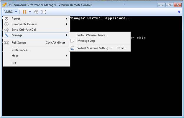
3. Set up OnCommand Performance Manager by answering the following questions in the console window:
Geographic area: <<Enter your geographic location>>
Time zone: <<Select the city or region corresponding to your time zone>>
These commands complete the network configuration checks, generates SSL certificates and starts the OnCommand Performance Manager services.
1. To Create a Maintenance User account, run the following commands:
![]() Note: The maintenance user manages and maintains the settings on the OnCommand Performance Manager virtual appliance.
Note: The maintenance user manages and maintains the settings on the OnCommand Performance Manager virtual appliance.
Username : admin
Enter new UNIX password: <<var_password>>
Retype new UNIX password: <<var_password>>
2. Using a web browser navigate to the OnCommand Performance Manager using URL: https:// <<var_oncommand_pm_ip>>.
3. Log in using the Maintenance User account (admin) credentials.
4. Enter a Maintenance User Email Address, SMTP Mail Server information, and the NTP server IP address. Click Save and go to next step.
5. Select Yes option to enable AutoSupport capabilities. Click Save and go to next step.
6. Click Save and go to next step.
7. Enter the storage cluster host name or IP address, the storage cluster admin user name, and the storage cluster admin password. Click Add Cluster, then click Save and Complete Configuration.
8. After the cluster is added it can be accessed by clicking on Administration > Manage Data Sources.
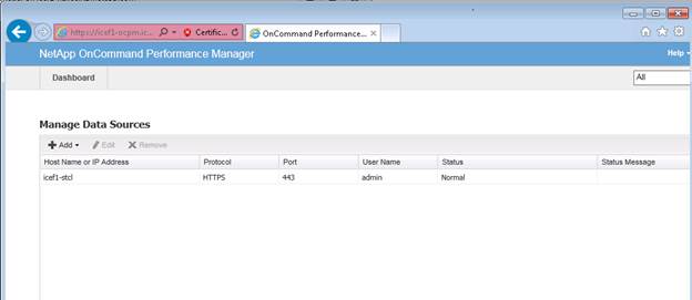
Link OnCommand Performance Manager to OnCommand Unified Manager
1. Using a web browser navigate to the OnCommand Unified Manager using URL: https:// <<var_oncommand_server_ip>>. Log in with the Maintenance user id and password setup earlier.
2. In the OnCommand Unified Manager web interface, select Administrator > Manage Users to set up an Event Publication user.
3. Click Add to add a user.
4. Leave the Type set to Local User. Use eventpub as the Name and enter and confirm a password. Enter an email address for this user and set the Role to Event Publisher. Click Add.
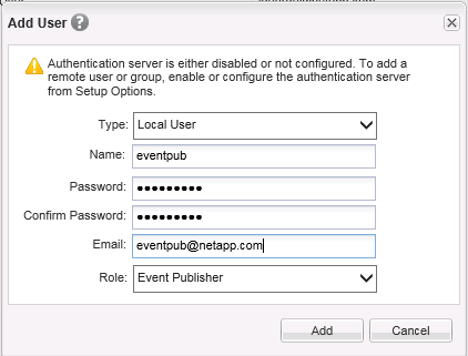
5. At the OnCommand Performance Manager console window, log into the Command Line Interface with the Maintenance User (admin) defined earlier.
6. Enter 5 to select Unified Manager Connection.
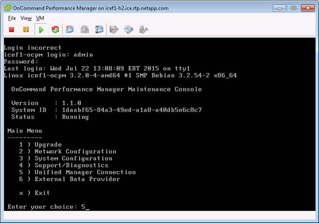
7. Enter 2 to Add / Modify Unified Manager Server Connection.
8. Enter y to continue.
9. Enter the OnCommand Unified Manager FQDN or IP Address.
10. Hit Enter to accept the default port 443.
11. Enter y to accept the Unified Manager Security Certificate.
12. Enter eventpub for the Event Publisher User Name.
13. Enter the eventpub password.
14. Enter y to accept the entered settings.
15. Select Yes option to enable AutoSupport capabilities. Click Save and go to next step.
16. Press any key to continue.
17. Exit the OnCommand Performance Manager console. OnCommand Performance Manager events will now appear in the OnCommand Unified Manager Dashboard.
NetApp NFS Plug-In 1.0.21 for VMware VAAI
Enable VMware vStorage for NFS in Clustered Data ONTAP
To enable VMware vStorage for NFS in clustered Data ONTAP, complete the following steps:
1. From an SSH session to the storage cluster management address, log in with the admin user name and password.
2. Enable vStorage on the Vserver.
vserver nfs modify –vserver Infra-SVM -vstorage enabled
3. Verify that the export policy rules are set up correctly.
vserver export-policy rule show –vserver Infra-SVM
Sample output:
NetApp::> vserver export-policy rule show -vserver Infra-SVM
Policy Rule Access Client RO
Vserver Name Index Protocol Match Rule
------------ --------------- ------ -------- --------------------- ---------
Infra-SVM default 1 nfs 192.168.170.61 sys
Infra-SVM default 2 nfs 192.168.170.60 sys
Infra-SVM default 3 nfs 192.168.170.58 sys
Infra-SVM default 4 nfs 192.168.170.59 sys
Infra-SVM default 5 nfs 192.168.170.62 sys
Infra-SVM default 6 nfs 192.168.170.63 sys
6 entries were displayed.
4. The access protocol for the FlexPod policy name should be NFS. If the access protocol is not nfs for a given rule index, run the following command to set NFS as the access protocol:
vserver export-policy rule modify –vserver Infra-SVM –policyname default –ruleindex <<var_rule_index>> -protocol nfs
Install NetApp NFS Plug-In for VMware VAAI
To install the NetApp NFS plug-in for VMware vStorage APIs for Array Integration (VAAI), complete the following steps:
1. From a console interface on the NetApp VSC VM, go to the Software Downloads page in the NetApp Support site.
2. Scroll down to locate the NetApp NFS Plug-in for VMware VAAI, select the ESXi5.x platform, and click Go.
3. Click View & Download.
4. Click CONTINUE.
5. Click Accept.
6. Download the .vib file of the most recent plug-in version to the VSC VM Desktop as NetAppNasPlugin.vib.
![]() Note: It is important that the file be saved as NetAppNasPlugin.vib.
Note: It is important that the file be saved as NetAppNasPlugin.vib.
7. On the VSC VM Desktop, move the NetAppNasPlugin.vib file to the C:\Program Files\NetApp\Virtual Storage Console\etc\vsc\web folder.
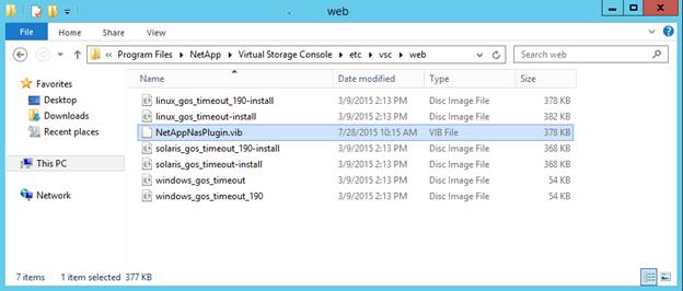
8. Go to the VMware vSphere Web Client and select VSC. Click NFS VAAI Tools. Make sure NFS Plug-in for VMware VAAI Version: 1.0-21 is shown.
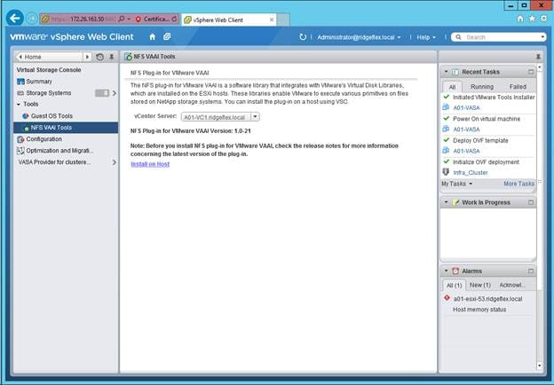
9. Click Install on Host. Select all Hosts on which you want to install the plug-in.
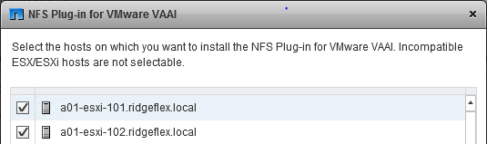
10. Click Install then click OK.
11. One at a time, put each ESXi host into Maintenance Mode, reboot the host, then Exit Maintenance Mode. It may be necessary to manually migrate VMs to the other host to allow the host to enter Maintenance Mode.
12. When the reboots have completed, in the vSphere Web Client from the Home page, click Storage, then select the infra_datastore_1 datastore. Select Settings under the Manage tab in the center pane. Hardware Acceleration should now show Supported on all hosts as shown below. All NFS datastores should now support Hardware Acceleration.
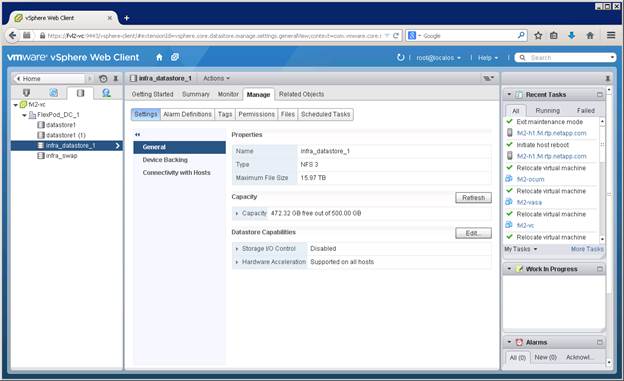
This section details the additional configuration to setup FCoE Boot using direct connection between AFF 8040 and UCS FI. The FCoE boot configuration can be used in addition to or instead of iSCSI Boot. In this appendix, FCoE boot is configured and enabled to coexist with the iSCSI boot option. This appendix assumes that the initial storage configuration section in this document has been completed. Customers can choose to replace the appropriate iSCSI specific sections of the main deployment guide with the FCoE sections in this appendix.
To support FCoE direct attached storage, the following additional physical connectivity is required:
Figure 7 FCoE Direct Attached Storage
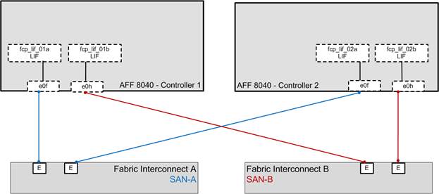
Storage Configuration
Add FCP as an Allowed Protocol in Infrastructure SVM
1. Add the FCP as an allowed protocol on the Infrastructure SVM.
vserver add-protocols -vserver Infra-SVM -protocols fcp
vserver show -vserver Infra-SVM -fields allowed-protocols
FCP Service in Clustered Data ONTAP
1. Create the FCP service on the Infrastructure SVM. This command also starts the FCP service and sets World Wide Node Name (WWNN) of the SVM.
fcp create -vserver Infra-SVM
fcp show
Create LUNs in Clustered Data ONTAP
1. Create two boot LUNS: VM-Host-Infra-01 and VM-Host-Infra-02.
lun create -vserver Infra-SVM -volume esxi_boot -lun VM-Host-Infra-01 -size 10GB -ostype vmware -space-reserve disabled
lun create -vserver Infra-SVM -volume esxi_boot -lun VM-Host-Infra-02 -size 10GB -ostype vmware -space-reserve disabled
Ensure FCoE Ports are Online
1. Check the status of the FCoE adapter ports used for Direct Connect.
fcp adapter show -fields state
2. If ports 0f and 0h on each node are not in the up state, use the following command to bring them up.
fcp adapter modify –node <var_node> -adapter <adapter> -state up
fcp adapter show -fields state
FCoE LIF in Clustered Data ONTAP
1. Create FCoE logical interfaces (LIFs).
network interface create -vserver Infra-SVM -lif fcp_lif01a -role data -data-protocol fcp -home-node <<var_node01>> -home-port 0f -status-admin up
network interface create -vserver Infra-SVM -lif fcp_lif01b -role data -data-protocol fcp -home-node <<var_node01>> -home-port 0h -status-admin up
network interface create -vserver Infra-SVM -lif fcp_lif02a -role data -data-protocol fcp -home-node <<var_node02>> -home-port 0f -status-admin up
network interface create -vserver Infra-SVM -lif fcp_lif02b -role data -data-protocol fcp -home-node <<var_node02>> -home-port 0h -status-admin up
network interface show –vserver Infra-SVM
Server (UCS) Configuration
Place Cisco UCS Fabric Interconnects in Fiber Channel Switching Mode
To use FCoE Appliance Ports, the Cisco UCS Fabric Interconnects must be placed in Fiber Channel Switching Mode. Complete the following steps:
1. In Cisco UCS Manager, click the Equipment tab in the navigation pane.
2. Expand Fabric Interconnects and select Fabric Interconnect B.
![]() Note: This next step will reboot both UCS Fabric Interconnects. If any servers are running on this system, they should be shut down before this step is executed.
Note: This next step will reboot both UCS Fabric Interconnects. If any servers are running on this system, they should be shut down before this step is executed.
3. In the Actions pane, select Set FC Switching Mode. Click Yes. Click OK.
4. After the Fabric Interconnects have rebooted, log back into UCS Manager.
5. Expand Fabric Interconnects and select Fabric Interconnects.
6. For each Fabric Interconnect, verify under Status that the FC Mode is now Switch.
Enable FCoE Storage Ports
To enable FCoE ports, complete the following steps:
1. In Cisco UCS Manager, click the Equipment tab in the navigation pane.
2. Select Equipment > Fabric Interconnects > Fabric Interconnect A (primary) > Fixed Module.
3. Expand Ethernet Ports.
4. Select ports 13 and 14 that are connected to the FCoE ports on the storage controllers, right-click them, and select Configure as FCoE Storage Port. Click Yes to confirm.
5. Select Equipment > Fabric Interconnects > Fabric Interconnect B (subordinate) > Fixed Module.
6. Expand Ethernet Ports.
7. Select ports 13 and 14 that are connected to the FCoE ports on the storage controllers, right-click them, and select Configure as FCoE Storage Port. Click Yes to confirm.
Create a WWNN Pool for FCoE Boot
To configure the necessary WWNN pool for the Cisco UCS environment, complete the following steps on Cisco UCS manager.
1. Select the SAN tab on the left.
2. Select Pools > root.
3. Right-click WWNN Pools under the root organization.
4. Select Create WWNN Pool to create the WWNN pool.
5. Enter WWNN_Pool for the name of the WWNN pool.
6. Optional: Enter a description for the WWNN pool.
7. Select Sequential for Assignment Order.
8. Click Next.
9. Click Add.
10. Modify the From field as necessary for this UCS Environment.
11. Specify a size of the WWNN block sufficient to support the available server resources.
12. Click OK.

13. Click Finish.
14. In the message box that displays, click OK.
Create WWPN Pools
To configure the necessary WWPN pools for the Cisco UCS environment, complete the following steps:
1. In Cisco UCS Manager, click the SAN tab in the navigation pane.
2. Select Pools > root.
![]() Note: In this procedure, two WWPN pools are created, one for each switching fabric.
Note: In this procedure, two WWPN pools are created, one for each switching fabric.
3. Right-click WWPN Pools under the root organization.
4. Select Create WWPN Pool to create the WWPN pool.
5. Enter WWPN_Pool_A as the name of the WWPN pool.
6. Optional: Enter a description for the WWPN pool.
7. Select Sequential for Assignment Order.
8. Click Next.
9. Click Add.
10. Specify a starting WWPN.
![]() Note: For the FlexPod solution, the recommendation is to place 0A in the next-to-last octet of the starting WWPN to identify all of the WWPNs as fabric A addresses.
Note: For the FlexPod solution, the recommendation is to place 0A in the next-to-last octet of the starting WWPN to identify all of the WWPNs as fabric A addresses.
11. Specify a size for the WWPN pool that is sufficient to support the available blade or server resources.

12. Click OK.
13. Click Finish.
14. In the confirmation message, click OK.
15. Right-click WWPN Pools under the root organization.
16. Select Create WWPN Pool to create the WWPN pool.
17. Enter WWPN_Pool_B as the name of the WWPN pool.
18. Optional: Enter a description for the WWPN pool.
19. Select Sequential for Assignment Order.
20. Click Next.
21. Click Add.
22. Specify a starting WWPN.
![]() Note: For the FlexPod solution, it is recommended to place 0B in the next to last octet of the starting WWPN to identify all the WWPNs in this pool as fabric B addresses.
Note: For the FlexPod solution, it is recommended to place 0B in the next to last octet of the starting WWPN to identify all the WWPNs in this pool as fabric B addresses.
23. Specify a size for the WWPN address pool that is sufficient to support the available blade or server resources.
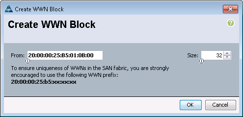
24. Click OK.
25. Click Finish.
26. In the confirmation message, click OK.
Create Server Pool
To configure specific server pool for servers supporting FCoE boot, complete the following steps:
![]() Note: Consider creating unique server pools to achieve the granularity that is required in your environment.
Note: Consider creating unique server pools to achieve the granularity that is required in your environment.
1. In Cisco UCS Manager, click the Servers tab in the navigation pane.
2. Select Pools > root.
3. Right-click Server Pools.
4. Select Create Server Pool.
5. Enter Infra_FCoE_Pool as the name of the server pool.
6. Optional: Enter a description for the server pool.
7. Click Next.
8. Select two (or more) servers to be used for the VMware management cluster and click >> to add them to the Infra_FCoE_Pool server pool.
9. Click Finish.
10. Click OK.
Create VSANs
To configure the necessary virtual storage area networks (VSANs) for the Cisco UCS environment, complete the following steps:
1. In Cisco UCS Manager, click the SAN tab in the navigation pane.
![]() Note: In this procedure, two VSANs are created.
Note: In this procedure, two VSANs are created.
2. Select SAN > SAN Cloud.
3. Right-click VSANs.
4. Select Create VSAN.
5. Enter VSAN_A as the name of the VSAN to be used for Fabric A
6. Select Enabled for FC Zoning.
7. Select Fabric A.
8. Enter a unique VSAN ID and a corresponding FCoE VLAN ID. It is recommended use the same ID for both parameters and to use something other than 1.
9. Click OK, and then click OK again.
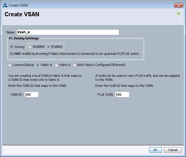
10. Under SAN Cloud, right-click VSANs.
11. Select Create VSAN.
12. Enter VSAN_B as the name of the VSAN to be used for Fabric B.
13. Select Enabled for FC Zoning.
14. Select Fabric B.
15. Enter a unique VSAN ID and a corresponding FCoE VLAN ID. It is recommended use the same ID for both parameters and to use something other than 1.
16. Click OK, and then click OK again.
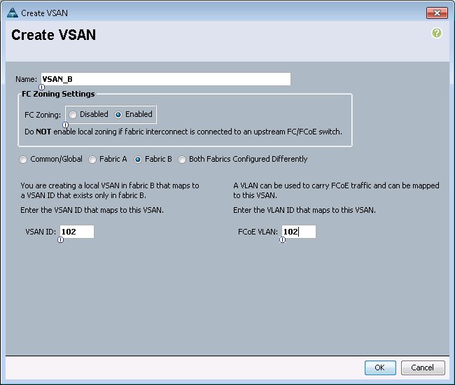
17. Under Storage Cloud, right-click VSANs.
18. Select Create Storage VSAN.
19. Enter VSAN_A as the name of the VSAN to be used for Fabric A.
20. Select Enabled for FC Zoning.
21. Select Fabric A.
22. Enter the same unique VSAN ID and corresponding FCoE VLAN ID that you entered for Fabric A above.
23. Click OK, and then click OK again.
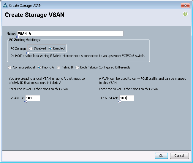
24. Under Storage Cloud, right-click VSANs.
25. Select Create Storage VSAN.
26. Enter VSAN_B as the name of the VSAN to be used for Fabric B.
27. Select Enabled for FC Zoning.
28. Select Fabric B.
29. Enter the same unique VSAN ID and corresponding FCoE VLAN ID that you entered for Fabric B above.
30. Click OK, and then click OK again.
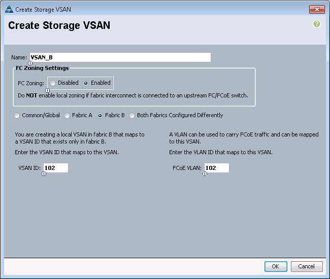
Assign VSANs to FCoE Storage Ports
To assign the necessary virtual storage area networks (VSANs) to the FCoE Storage Ports for the Cisco UCS environment, complete the following steps:
1. In Cisco UCS Manager, click the SAN tab in the navigation pane.
2. Select SAN > Storage Cloud.
3. Expand Fabric A and Storage FCoE Interfaces.
4. Right-click FCoE Interface 1/13 and select Storage FCoE Interface.
5. Set the User Label to the storage controller name and port that this interface is connected to.
6. Select VSAN_A as the VSAN.
7. Click OK.

8. Expand Fabric A and Storage FCoE Interfaces.
9. Right-click FCoE Interface 1/14 and select Storage FCoE.
10. Set the User Label to the storage controller name and port that this interface is connected to.
11. Select VSAN_A as the VSAN.
12. Click OK.

13. Expand Fabric B and Storage FCoE Interfaces.
14. Right-click FCoE Interface 1/13 and select Storage FCoE.
15. Set the User Label to the storage controller name and port that this interface is connected to.
16. Select VSAN_B as the VSAN.
17. Click OK.
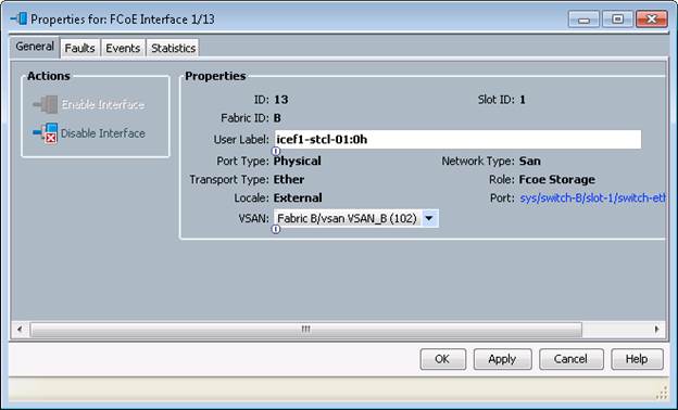
18. Expand Fabric B and Storage FCoE Interfaces.
19. Right-click FCoE Interface 1/14 and select Storage FCoE Interface.
20. Set the User Label to the storage controller name and port that this interface is connected to.
21. Select VSAN_B as the VSAN.
22. Click OK.

Create Storage Connection Policies for FCoE Zoning
To create Storage Connection Policies for the FCoE Zoning, complete the following steps:
1. In Cisco UCS Manager, click the SAN tab in the navigation pane.
2. Select Policies > root.
3. Right-click Storage Connection Policies.
4. Select Create Storage Connection Policy.
5. Enter Infra-Fabric-A as the name of the policy.
6. Select the Single Initiator Multiple Targets Zoning Type.
7. Click the Plus Sign on the right to add a zoning target.
8. Enter the WWPN for fcp_lif01a from the storage cluster. This WWPN can be obtained by logging into the storage cluster CLI and entering the network interface show –vserver Infra-SVM command.
9. Select Path A and VSAN_A.
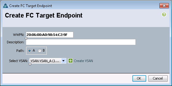
10. Click OK.
11. Click the Plus Sign on the right to add a second zoning target.
12. Enter the WWPN for fcp_lif02a from the storage cluster. This WWPN can be obtained by logging into the storage cluster CLI and entering the network interface show –vserver Infra-SVM command.
13. Select Path A and VSAN_A.
14. Click OK, and then click OK again.

15. Right-click Storage Connection Policies.
16. Select Create Storage Connection Policy
17. Enter Infra-Fabric-B as the name of the policy.
18. Select the Single Initiator Multiple Targets Zoning Type.
19. Click the Plus Sign on the right to add a zoning target.
20. Enter the WWPN for fcp_lif01b from the storage cluster. This WWPN can be obtained by logging into the storage cluster CLI and entering the network interface show –vserver Infra-SVM command.
21. Select Path B and VSAN_B.

22. Click OK.
23. Click the Plus Sign on the right to add a second zoning target.
24. Enter the WWPN for fcp_lif02b from the storage cluster. This WWPN can be obtained by logging into the storage cluster CLI and entering the network interface show –vserver Infra-SVM command.
25. Select Path B and VSAN_B.
26. Click OK, and then click OK again.
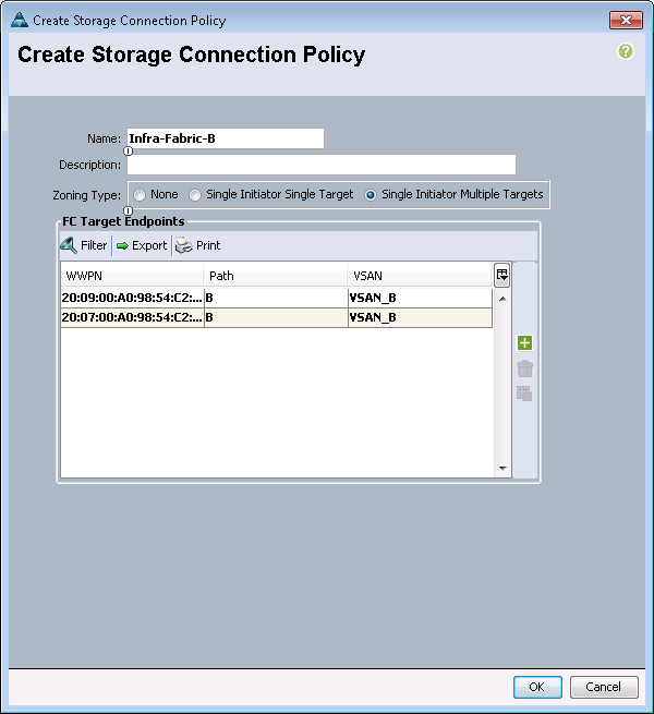
Create vHBA Templates
To create the necessary virtual host bus adapter (vHBA) templates for the Cisco UCS environment, complete the following steps:
1. In Cisco UCS Manager, click the SAN tab in the navigation pane.
2. Select Policies > root.
3. Right-click vHBA Templates.
4. Select Create vHBA Template.
5. Enter vHBA_Template_A as the vHBA template name.
6. Keep Fabric A selected.
7. Select VSAN_A.
8. Leave Initial Template as the Template Type.
9. Select WWPN_Pool_A as the WWPN Pool.
10. Click OK to create the vHBA template.
11. Click OK.
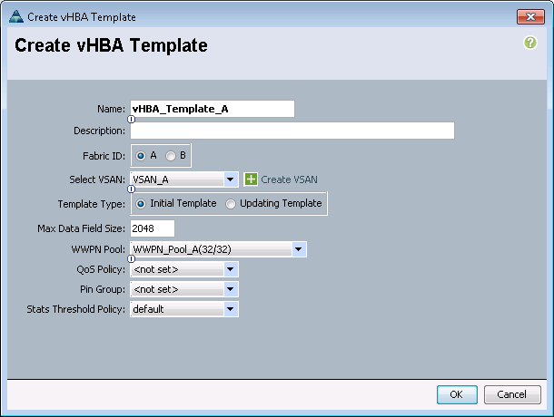
12. Right-click vHBA Templates.
13. Select Create vHBA Template.
14. Enter vHBA_Template_B as the vHBA template name.
15. Select Fabric B as the Fabric ID.
16. Select VSAN_B.
17. Leave Initial Template as the Template Type.
18. Select WWPN_Pool_B as the WWPN Pool.
19. Click OK to create the vHBA template.
20. Click OK.
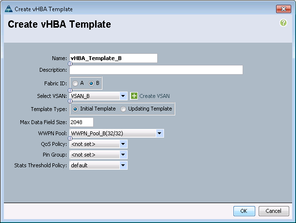
Create Boot Policy
This procedure applies to a Cisco UCS environment in which two FCoE logical interfaces (LIFs) are on cluster node 1 (fcp_lif01a and fcp_lif01b) and two FCoE LIFs are on cluster node 2 (fcp_lif02a and fcp_lif02b). Also, it is assumed that the A LIFs are connected to Fabric A (Cisco UCS 6248UP A) and the B LIFs are connected to Fabric B (Cisco UCS 6248UP B).
A single boot policy is configured in this procedure. This policy configures the primary target to be fcp_lif01a.
To create a boot policy for the Cisco UCS environment, complete the following steps:
1. In Cisco UCS Manager, in the navigation pane, click the Servers tab.
2. Select Policies > root.
3. Right-click Boot Policies.
4. Select Create Boot Policy.
5. Enter Boot-Fabric-A as the name for the boot policy.
6. Optional: Enter a description for the boot policy.
![]() Note: Do not select the Reboot on Boot Order Change checkbox.
Note: Do not select the Reboot on Boot Order Change checkbox.
7. Expand the Local Devices drop-down menu, select Add Remote CD/DVD.
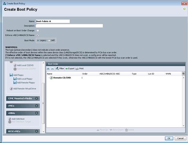
8. Expand the vHBAs drop-down menu and select Add SAN Boot.
9. In the Add SAN Boot dialog box, enter Fabric-A in the vHBA field.
10. Confirm that Primary is selected for the Type option.
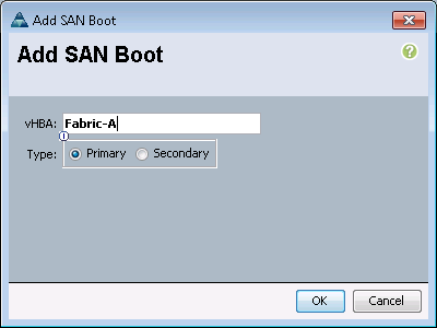
11. Click OK to add the SAN boot initiator.
12. From the vHBA drop-down menu, select Add SAN Boot Target.
13. Keep 0 as the value for Boot Target LUN.
14. Enter the WWPN for fcp_lif01a.
![]() Note: To obtain this information, log in to the storage cluster and run the network interface show command.
Note: To obtain this information, log in to the storage cluster and run the network interface show command.
15. Select Primary for the SAN boot target type.

16. Click OK to add the SAN boot target.
17. From the vHBA drop-down menu, select Add SAN Boot Target.
18. Enter 0 as the value for Boot Target LUN.
19. Enter the WWPN for fcp_lif02a.

20. Click OK to add the SAN boot target.
21. From the vHBA drop-down menu, select Add SAN Boot.
22. In the Add SAN Boot dialog box, enter Fabric-B in the vHBA box.
23. The SAN boot type should automatically be set to Secondary, and the Type option should be unavailable.
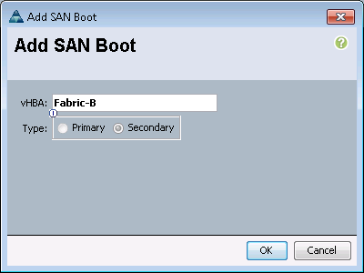
24. Click OK to add the SAN boot initiator.
25. From the vHBA drop-down menu, select Add SAN Boot Target.
26. Keep 0 as the value for Boot Target LUN.
27. Enter the WWPN for fcp_lif01b.
28. Select Primary for the SAN boot target type.
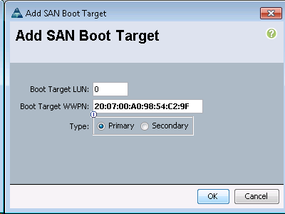 John
John
29. Click OK to add the SAN boot target.
30. From the vHBA drop-down menu, select Add SAN Boot Target.
31. Keep 0 as the value for Boot Target LUN.
32. Enter the WWPN for fcp_lif02b.

33. Click OK to add the SAN boot target.
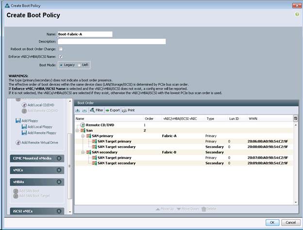
34. Click OK, then click OK again to create the boot policy.
Create Service Profile Template
In this procedure, one service profile template is created for fabric A boot. To create the service profile template, complete the following steps:
1. In Cisco UCS Manager, click the Servers tab in the navigation pane.
2. Select Service Profile Templates > root.
3. Right-click root.
4. Select Create Service Profile Template to open the Create Service Profile Template wizard.
5. Identify the service profile template:
a. Enter VM-Host-Infra-Fabric-A* as the name of the service profile template. This service profile template is configured to boot from node 1 on fabric A.
b. Select the Updating Template option.
c. Under UUID, select UUID_Pool as the UUID pool.
d. Click Next.
![]() * Note: If this name has already been utilized for the Infrastructure hosts utilizing iSCSI boot, please choose a different name or append fcoe to this template name
* Note: If this name has already been utilized for the Infrastructure hosts utilizing iSCSI boot, please choose a different name or append fcoe to this template name
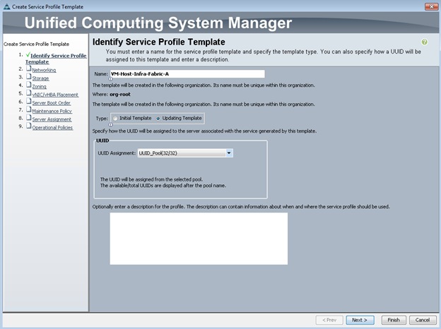
Configure Networking Options
1. To configure the networking options, 6 vNIC interfaces will be added for Infrastructure ESXi hosts:
2. Keep the default setting for Dynamic vNIC Connection Policy.
3. Select the Expert option to configure the LAN connectivity.
4. Click the upper Add button to add a vNIC to the template.
5. In the Create vNIC dialog box, enter vNIC-A as the name of the vNIC.
6. Select the Use vNIC Template checkbox.
7. In the vNIC Template list, select vNIC_Template_A.
8. In the Adapter Policy list, select VMWare.
9. Click OK to add this vNIC to the template.
10. On the Networking page of the wizard, click the upper Add button to add another vNIC to the template.
11. In the Create vNIC box, enter vNIC-B as the name of the vNIC.
12. Select the Use vNIC Template checkbox.
13. In the vNIC Template list, select vNIC_Template_B.
14. In the Adapter Policy list, select VMWare.
15. Click OK to add the vNIC to the template.
16. On the Networking page of the wizard, click the upper Add button to add another vNIC to the template.
17. In the Create vNIC box, enter OOB-A as the name of the vNIC.
18. Select the Use vNIC Template checkbox.
19. In the vNIC Template list, select OOB-A.
20. In the Adapter Policy list, select VMWare.
21. Click OK to add the vNIC to the template.
22. On the Networking page of the wizard, click the upper Add button to add another vNIC to the template.
23. In the Create vNIC box, enter OOB-B as the name of the vNIC.
24. Select the Use vNIC Template checkbox.
25. In the vNIC Template list, select OOB-B.
26. In the Adapter Policy list, select VMWare.
27. Click OK to add the vNIC to the template.
![]() Note: The next two vNIC interfaces are only needed for Infrastructure ESXi Hosts. These interfaces enable NFS access using NFS specific vSwitch and static EPG mapping. ESXi servers not hosting infrastructure VMs, use VDS for NFS access to application specific SVMs.
Note: The next two vNIC interfaces are only needed for Infrastructure ESXi Hosts. These interfaces enable NFS access using NFS specific vSwitch and static EPG mapping. ESXi servers not hosting infrastructure VMs, use VDS for NFS access to application specific SVMs.
28. On the Networking page of the wizard, click the upper Add button to add another vNIC to the template.
29. In the Create vNIC box, enter NFS-A as the name of the vNIC.
30. Select the Use vNIC Template checkbox.
31. In the vNIC Template list, select Infra_NFS_A.
32. In the Adapter Policy list, select VMWare.
33. Click OK to add the vNIC to the template.
34. On the Networking page of the wizard, click the upper Add button to add another vNIC to the template.
35. In the Create vNIC box, enter NFS-B as the name of the vNIC.
36. Select the Use vNIC Template checkbox.
37. In the vNIC Template list, select Infra_NFS_B.
38. In the Adapter Policy list, select VMWare.
39. Click OK to add the vNIC to the template.
40. Verify 6 vNIC interfaces are present.
41. Review the table in the Networking page to make sure that all vNICs were created.
42. Click Next.
Configure Storage Options
1. Select a local disk configuration policy:
a. If the server in question has local disks, select default in the Local Storage list.
b. If the server in question does not have local disks, select SAN-Boot.
2. Select the Expert option for the How would you like to configure SAN connectivity? field.
3. Select WWNN_Pool for the WWNN Assignment.
4. Click the Add button to add a vHBA.
5. Enter Fabric-A as the vHBA name and select the checkbox for Use vHBA Template.
6. Select the vHBA_Template_A vHBA Template and the VMWare Adapter Policy.
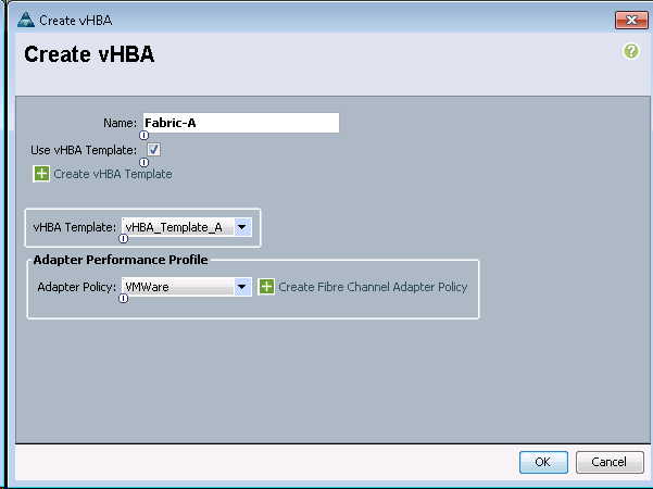
7. Click OK to add the vHBA.
8. Click the Add button to add a vHBA.
9. Enter Fabric-B as the vHBA name and select the checkbox for Use vHBA Template.
10. Select the vHBA_Template_B vHBA Template and the VMWare Adapter Policy.
11. Click OK to add the vHBA.
12. Click Next.
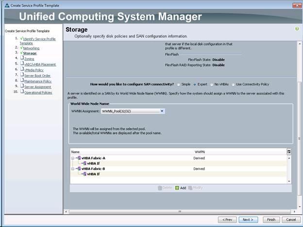
Configure Zoning Options
1. In the Zoning window, click the Add button.
2. Name the vHBA Initiator Group, Fabric-A and select the Infra-Fabric-A Storage Connection Policy.
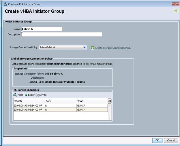
3. Click OK to add the vHBA Initiator Group.
4. In the Zonig window, click the Add button.
5. Name the vHBA Initiator Group, Fabric-B and select the Infra-Fabric-B Storage Connection Policy.
6. Click OK to add the vHBA Initiator Group.
7. In the Zoning window, select Fabric A in the list of vHBA Initiators and Fabric-A in the list of vHBA Initiator Groups.
8. Click the >> Add To >> button.
9. In the Zoning window, select Fabric B in the list of vHBA Initiators and Fabric-B in the list of vHBA Initiator Groups.
10. Click the >> Add To >> button.
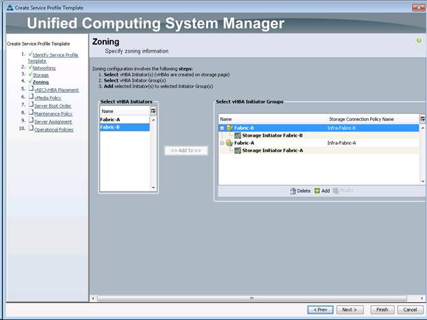
11. Click Next.
vNIC/vHBA Placement
1. In the Select Placement list, select the VM-Host-Infra placement policy.
2. Select vCon1 and assign the vHBAs/vNICs to the virtual network interfaces policy in the following order:
a. vNIC-A
b. vNIC-B
c. OOB-A
d. OOB-B
e. NFS-A
f. NFS-B
g. vHBA Fabric-A
h. vHBA Fabric-B
3. Review the table to verify that all vNICs and vHBAs were assigned to the policy in the appropriate order.
4. Click Next.
Server Boot Order
1. Select Boot-Fabric-A for Boot Policy.
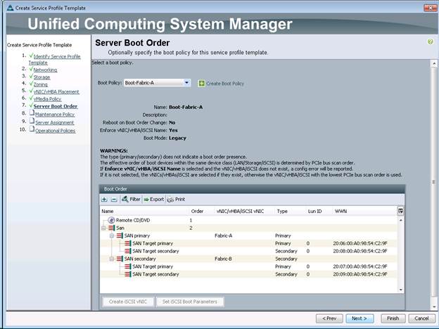
2. Review the table to make sure that all boot devices were created and identified. Verify that the boot devices are in the correct boot sequence.
3. Click Next to continue to the next section.
Maintenance Policy
1. Select the default Maintenance Policy.
2. Click Next.
Server Assignment
1. In the Pool Assignment list, select Infra_Pool.
2. Optional: Select a Server Pool Qualification policy.
3. Select Down as the power state to be applied when the profile is associated with the server.
4. Expand Firmware Management at the bottom of the page and select VM-Host-Infra from the Host Firmware list.
5. Click Next.
Operational Policies
1. In the BIOS Policy list, select VM-Host-Infra.
2. Expand Power Control Policy Configuration and select No-Power-Cap in the Power Control Policy list.

3. Click Finish to create the service profile template.
4. Click OK in the confirmation message.
Create Service Profiles
To create service profiles from the service profile template, complete the following steps:
1. In Cisco UCS Manager, click the Servers tab in the navigation pane.
2. Select Service Profile Templates > root > Service Template VM-Host-Infra-Fabric-A.
3. Right-click VM-Host-Infra-Fabric-A and select Create Service Profiles from.
4. Enter VM-Host-Infra-0 as the service profile prefix.
5. Enter 1 as Name Suffix Starting Number
6. Enter 1 as the Number of Instances. Adjust the number based on required number of servers.
7. Click OK to create the service profile.
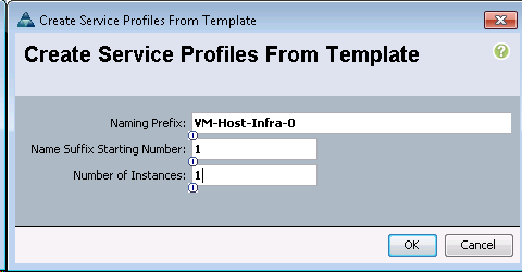
8. Click OK in the confirmation message.
Clustered Data ONTAP SAN Boot Storage Setup
Create Igroups
1. From the cluster management node SSH connection, enter the following:
igroup create –vserver Infra-SVM –igroup VM-Host-Infra-01 –protocol fcp –ostype vmware –initiator <<var_vm_host_infra_01_A_wwpn>>, <<var_vm_host_infra_01_B_wwpn>>
igroup create –vserver Infra-SVM –igroup VM-Host-Infra-02 –protocol fcp –ostype vmware –initiator <<var_vm_host_infra_02_A_wwpn>>, <<var_vm_host_infra_02_B_wwpn>>
igroup create –vserver Infra-SVM –igroup MGMT-Hosts –protocol fcp –ostype vmware –initiator <<var_vm_host_infra_01_A_wwpn>>, <<var_vm_host_infra_01_B_wwpn>>, <<var_vm_host_infra_02_A_wwpn>>, <<var_vm_host_infra_02_B_wwpn>>
![]() Note: To view the three igroups just recently created, enter igroup show.
Note: To view the three igroups just recently created, enter igroup show.
Map Boot LUNs to Igroups
1. From the cluster management SSH connection, enter the following:
lun map –vserver Infra-SVM –volume esxi_boot –lun VM-Host-Infra-01 –igroup VM-Host-Infra-01 –lun-id 0
lun map –vserver Infra-SVM –volume esxi_boot –lun VM-Host-Infra-02 –igroup VM-Host-Infra-02 –lun-id 0
Haseeb Niazi, Technical Marketing Engineer, Cisco UCS Data Center Solutions Engineering, Cisco Systems Inc.
Haseeb Niazi has over 16 years of experience at Cisco focused on Data Center, Security, WAN Optimization, and related technologies. As a member of various solution teams and advanced services, Haseeb has helped many enterprise and service provider customers evaluate and deploy a wide range of Cisco solutions. Haseeb holds a master's degree in Computer Engineering from the University of Southern California.
Lindsey Street, Solutions Architect, Infrastructure and Cloud Engineering, NetApp
Lindsey Street is a Solutions Architect in the NetApp Infrastructure and Cloud Engineering team. She focuses on the architecture, implementation, compatibility, and security of innovative vendor technologies to develop competitive and high-performance end-to-end cloud solutions for customers. Lindsey started her career in 2006 at Nortel as an interoperability test engineer, testing customer equipment interoperability for certification. Lindsey has her Bachelors of Science degree in Computer Networking and her Masters of Science in Information Security from East Carolina University.
John George, Reference Architect, Infrastructure and Cloud Engineering, NetApp
John George is a Reference Architect in the NetApp Infrastructure and Cloud Engineering team and is focused on developing, validating, and supporting cloud infrastructure solutions that include NetApp products. Before his current role, he supported and administered Nortel's worldwide training network and VPN infrastructure. John holds a Master's degree in computer engineering from Clemson University.
Acknowledgements
For their support and contribution to the design, validation, and creation of this Cisco Validated Design, the authors would like to thank:
· Chris O' Brien, Cisco Systems Inc.
 Feedback