Cisco UCS and Nimble Unified Flash Fabric with VMWare vSphere 6.5
Available Languages

Cisco UCS and Nimble Unified Flash Fabric with VMWare vSphere 6.5
Deploying a Cisco-Nimble Integrated Infrastructure Platform based on Cisco UCS, Nimble Unified Flash Fabric (AF7000 All Flash Array and CS5000 Adaptive Flash Array), Cisco MDS Switches and Cisco Nexus Switches
Last Updated: April 19, 2017

About the Cisco Validated Design (CVD) Program
The CVD program consists of systems and solutions designed, tested, and documented to facilitate faster, more reliable, and more predictable customer deployments. For more information visit
http://www.cisco.com/go/designzone.
ALL DESIGNS, SPECIFICATIONS, STATEMENTS, INFORMATION, AND RECOMMENDATIONS (COLLECTIVELY, "DESIGNS") IN THIS MANUAL ARE PRESENTED "AS IS," WITH ALL FAULTS. CISCO AND ITS SUPPLIERS DISCLAIM ALL WARRANTIES, INCLUDING, WITHOUT LIMITATION, THE WARRANTY OF MERCHANTABILITY, FITNESS FOR A PARTICULAR PURPOSE AND NONINFRINGEMENT OR ARISING FROM A COURSE OF DEALING, USAGE, OR TRADE PRACTICE. IN NO EVENT SHALL CISCO OR ITS SUPPLIERS BE LIABLE FOR ANY INDIRECT, SPECIAL, CONSEQUENTIAL, OR INCIDENTAL DAMAGES, INCLUDING, WITHOUT LIMITATION, LOST PROFITS OR LOSS OR DAMAGE TO DATA ARISING OUT OF THE USE OR INABILITY TO USE THE DESIGNS, EVEN IF CISCO OR ITS SUPPLIERS HAVE BEEN ADVISED OF THE POSSIBILITY OF SUCH DAMAGES.
THE DESIGNS ARE SUBJECT TO CHANGE WITHOUT NOTICE. USERS ARE SOLELY RESPONSIBLE FOR THEIR APPLICATION OF THE DESIGNS. THE DESIGNS DO NOT CONSTITUTE THE TECHNICAL OR OTHER PROFESSIONAL ADVICE OF CISCO, ITS SUPPLIERS OR PARTNERS. USERS SHOULD CONSULT THEIR OWN TECHNICAL ADVISORS BEFORE IMPLEMENTING THE DESIGNS. RESULTS MAY VARY DEPENDING ON FACTORS NOT TESTED BY CISCO.
CCDE, CCENT, Cisco Eos, Cisco Lumin, Cisco Nexus, Cisco StadiumVision, Cisco TelePresence, Cisco WebEx, the Cisco logo, DCE, and Welcome to the Human Network are trademarks; Changing the Way We Work, Live, Play, and Learn and Cisco Store are service marks; and Access Registrar, Aironet, AsyncOS, Bringing the Meeting To You, Catalyst, CCDA, CCDP, CCIE, CCIP, CCNA, CCNP, CCSP, CCVP, Cisco, the Cisco Certified Internetwork Expert logo, Cisco IOS, Cisco Press, Cisco Systems, Cisco Systems Capital, the Cisco Systems logo, Cisco Unified Computing System (Cisco UCS), Cisco UCS B-Series Blade Servers, Cisco UCS C-Series Rack Servers, Cisco UCS S-Series Storage Servers, Cisco UCS Manager, Cisco UCS Management Software, Cisco Unified Fabric, Cisco Application Centric Infrastructure, Cisco Nexus 9000 Series, Cisco Nexus 7000 Series. Cisco Prime Data Center Network Manager, Cisco NX-OS Software, Cisco MDS Series, Cisco Unity, Collaboration Without Limitation, EtherFast, EtherSwitch, Event Center, Fast Step, Follow Me Browsing, FormShare, GigaDrive, HomeLink, Internet Quotient, IOS, iPhone, iQuick Study, LightStream, Linksys, MediaTone, MeetingPlace, MeetingPlace Chime Sound, MGX, Networkers, Networking Academy, Network Registrar, PCNow, PIX, PowerPanels, ProConnect, ScriptShare, SenderBase, SMARTnet, Spectrum Expert, StackWise, The Fastest Way to Increase Your Internet Quotient, TransPath, WebEx, and the WebEx logo are registered trademarks of Cisco Systems, Inc. and/or its affiliates in the United States and certain other countries.
All other trademarks mentioned in this document or website are the property of their respective owners. The use of the word partner does not imply a partnership relationship between Cisco and any other company. (0809R)
© 2017 Cisco Systems, Inc. All rights reserved.
Table of Contents
Validated Hardware and Software Matrix
Solution Deployment – LAN Network Configuration
Cisco Nexus Configuration Workflow
Base Setup – Configuration Dialog
Enabling Global Features and Settings
Configure vPC Domain, Peer-Link and Settings
Configure Network Interfaces for VPC Peer Links
Configure Network Interfaces to Cisco UCS Fabric Interconnects
Solution Deployment – Storage Array Configuration
Nimble Storage Configuration Workflow
Base Setup of Nimble Storage Array
Initialize Nimble Storage Array
Configure Nimble OS using the GUI
Configure Array to Send Email Notifications for Alerts (Optional)
Configure Arrays to Monitor VMware Environment using VMVision
Solution Deployment – SAN Fabric Configuration
Cisco MDS Configuration Workflow
Base Setup using Configuration Dialog
Enable Global Features and Settings
Create Port Channels to Cisco UCS Fabric Interconnects
Configure FC Interfaces to Unified Flash Fabric
Configure Device Aliases for Unified Flash Fabric
Solution Deployment – Cisco UCS Configuration
Cisco UCS Configuration Workflow
Cisco UCS Configuration – Base Setup
Initial Setup of Cisco Fabric Interconnects
Cisco UCS Manager – Configure NTP Server
Assign Block of IP addresses for KVM Access
Acknowledge Cisco UCS Chassis, Cisco UCS C-series and FEX
Enable Uplink Ports to Cisco Nexus 9000 Series Switches
Configure Port Channels on Uplink Ports to Cisco Nexus Switches
Enable Fibre Channels Ports to Cisco MDS 9100 Series Switches
Create VSAN for Fibre Channel Interfaces
Configure Port Channels on Fibre Channel Uplinks to Cisco MDS Switches.
Cisco UCS Configuration Backup
Cisco UCS Configuration – Server
Create SAN Connectivity Policy
Cisco UCS Configuration - Service Profile Template
Solution Deployment – Deploy New Host
Generate Service Profile for the New Host using a Service Profile Template.
Setup Nimble Storage Array for SAN Boot of Host
Collect Initiator WWPNs from the Host Service Profile
Create Initiator Group for Host
Setup SAN Fabric for SAN Boot of Host
Configure Device Aliases for the New Host
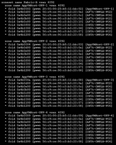
Create Zones and Zoneset for the New Host
SAN Boot and Install of ESXi on Host
KVM Console into Host from Cisco UCSM Web Interface
Setup ESXi Host for IP Management
Provision New Host without vCenter
Access Host Directly using vSphere Web Client
Update FNIC and ENIC Drivers on ESXi Host
Install Nimble Connection Manager (NCM)
Solution Deployment – vSphere Setup
Optional: Deploy VMware vCenter Appliance 6.5
Download vCenter Server Appliance (VCSA) ISO from VMware
Install vCenter Server Appliance
Setup vCenter for Datacenter, Cluster, DRS and HA
Specify Virtual Machine (VM) Swap File location – Cluster Level
Deploy High Availability for vCenter
Create vSphere Distributed Switch for Application VM Traffic
Workflow for vSphere Distributed Switch Configuration
Create vSphere Distributed Switch
Add Port Groups for Applications
Solution Deployment – Add and Setup New Host with vCenter
Update FNIC and ENIC Drivers on a ESXi Host
Install Nimble Connection Manager (NCM)
Verify Storage Configuration Post-NCM Install
Register Nimble vCenter Plugin
Specify Virtual Machine (VM) Swap File location – Host side
Setup ESXi Dump Collector - Host side
Configure ESXi Dump Collector using ESX Shell/CLI
Configure ESXi Dump Collector using a Host Profile
Setup vSphere vSwitch Networking on Host for Management and vMotion
Workflow for vSphere vSwitch Networking Setup
Configure vSwitch0 for Management
Add Host to vSphere Distributed Switch for Application VMs
Extract Host Profile to use as a template deploying additional hosts
Solution Deployment - Deploy High Availability for vCenter (Optional)
Add vCenter HA Vlan to Cisco UCS Fabric
Cisco Validated Designs (CVD) are systems and solutions that have been designed, tested and documented to facilitate and accelerate customer deployments. These designs incorporate a wide range of technologies and products into a portfolio of solutions that have been developed to address the business needs of a customer. CVDs deliver a validated design, documentation and support information to guide customers from design to deployment.
Cisco and Nimble have partnered to deliver a series of integrated solutions for Enterprise and Cloud datacenters by combining Cisco Unified Computing System (UCS), Cisco switching, and Nimble Storage arrays. The Cisco-Nimble solution covered in this document incorporates compute, network and storage best practices to deliver a resilient, scalable and flexible datacenter architecture. The design uses Cisco UCS servers for compute, VMware vSphere 6.5 hypervisor, Cisco Nexus 9000 series as the network platform and Cisco MDS 9000 Series switches for the Fibre Channel (FC) network to connect to the Nimble Storage AF7000 all flash and CS5000 adaptive flash arrays. The solution ensures compatibility between the components by testing the integrated architecture. The solution also provides documented design guidance, deployment guidance, and support through the planning, design, and implementation stages of a deployment.
Documentation for this CVD includes the following documents:
· Cisco-Nimble Solution Design Guide
· Cisco-Nimble Solution Deployment Guide
This document serves as the Cisco-Nimble Solution Deployment Guide. The Design Guide associated with this deployment guide can be found here.
Introduction
This document outlines the deployment procedures for implementing a Cisco-Nimble solution infrastructure solution based on VMware vSphere 6.5, Cisco UCS, Nimble Storage Unified Flash Fabric (AF7000 all flash array, CS5000 adaptive flash array), and Cisco switching (Nexus, MDS) switches.
Audience
The intended audience for this document includes, but is not limited to, sales engineers, field consultants, professional services, customer IT staff, partner engineering, and others who want to deploy data center architecture based on Cisco UCS and Nimble Storage Unified Flash Fabric.
The architecture outlined in this document provides a converged infrastructure solution based on Cisco UCS and Nimble Storage Unified Flash Fabric for Enterprise datacenters and private cloud deployments. The Cisco-Nimble solution integrates Cisco UCS compute, Nimble AF7000 all flash and CS5000 adaptive flash storage, Cisco Nexus 9000 Series platform switches and Cisco MDS Fabric switches to deliver a foundational platform that can support a wide range of application workloads. The solution delivers compute, storage, SAN and LAN connectivity in a highly resilient, flexible and scalable architecture. The modular architecture has the flexibility to scale up by adding resources or scale out by adding multiple units or modules of this solution.
Figure 1 shows the solution design built using the following components:
· Cisco Unified Computing System (UCS) – provides the compute resources, including blade and rack servers
· Cisco UCS 6200 Series Fabric Interconnects (FI) – for unified management and access to storage and LAN networks
· Cisco Nexus 9300 series switches – for connectivity to users, other LAN networks and Cisco UCS domains
· Cisco MDS fabric switches – provides a SAN fabric for Fibre Channel (FC) connectivity to storage
· Nimble AF7000 all flash array – provides all flash storage with SSD
· Nimble CS5000 adaptive flash array – provides hybrid flash storage with SSDs and HDDs
· VMware vSphere 6.5 – Hypervisor
The design uses 10 Gigabit Ethernet (GbE) connections between Cisco UCS and Nexus switches, along with 8G and 16G FC SAN connections to Nimble Storage through Cisco MDS switches. Each functional layer (compute, network, and storage) of the architecture is designed to be highly resilient with redundant links and components. The hosts are SAN booted with block-level access to both all flash and hybrid storage provided by Nimble Unified Flash Fabric. The solution also leverages the stateless server provisioning and management capabilities of Cisco UCS Manager with the wizard based provisioning and simplified storage management of Nimble storage to provide quick provisioning and deployment of infrastructure resources.
Figure 1 Cisco-Nimble Solution Design
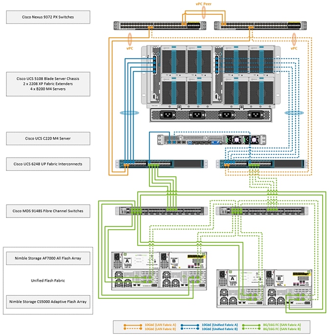
The SAN fabric in the design consists of a pair of redundant Cisco MDS 9148S switches, with 8G FC connections to Cisco UCS 6200 Series Fabric Interconnects and 16G FC connectivity to Nimble arrays. The architecture can also support 16G FC end-to-end by upgrading from Cisco UCS 6200 to 6300 Series Fabric Interconnects. Two SAN fabrics provide redundant paths for SAN boot and for accessing shared storage on Nimble.
The LAN design uses a pair of Cisco Nexus 9300 series switches deployed in a standalone mode and provide 10GbE connectivity to Cisco UCS FI. Cisco Nexus 9300 switches provides a migration path, with investment protection, to both 40GbE LAN and Cisco ACI. The solution can also support 100GbE LAN connectivity by upgrading to Nexus 93180 series switches.
Compute
Cisco UCS B-Series and C-Series servers provide the compute resources in this design. Several models of these servers are supported but Cisco UCS B200M4 and C220 M4 servers were used in validation.
The compute design consists of an infrastructure management POD and an application POD, each with dedicated hardware and running VMware ESXi 6.5 hypervisor.
The infrastructure POD hosts the management or the common infrastructure services that are necessary to deploy, operate and manage the entire deployment. For validation, common components such as Active Directory, DNS, DHCP, vCenter were deployed in the infrastructure management POD.
The application POD consists of any virtualized application hosted on Cisco UCS that the business requires. For validation, IOMeter virtual machines representing application VMs were hosted on the POD.
Features available at the hypervisor layer (for example, VMware clustering, high availability) are leveraged in both the infrastructure management and application PODs.
Depending on the size and needs of a deployment, infrastructure VMs could be deployed with Applications VMs on a single POD but this design assumes a dedicated POD for infrastructure management.
![]() The deployment guidance in this document assumes that the deployment environment already has an infrastructure management POD and therefore the focus of this document is on the deployment of an application POD.
The deployment guidance in this document assumes that the deployment environment already has an infrastructure management POD and therefore the focus of this document is on the deployment of an application POD.
From a connectivity standpoint, the compute resources (blade server chassis and rack mount servers) connect into a pair of Cisco UCS 6248 Fabric Interconnects. The blade server chassis connects to the FI through the Cisco FEX module located at the back of the chassis. The rack mount server uses the direct-attached design to connect directly into the FIs and does not use a FEX in this design.
Two Cisco UCS Fabric Interconnects are deployed in a cluster for redundancy and provide two fabric planes (FI-A, FI-B) that are completely independent of each other from a data plane perspective. In the event of a failure (or if the design only uses one FI), the fabric can be fully operational with one FI.
The FIs provide 10GbE connectivity to the LAN network infrastructure and 8G/16G FC connectivity to the SAN fabric. The FI provides 40Gbps of aggregate bandwidth to the LAN network and 64Gbps to the SAN network. Link aggregation using port channels are used on the unified fabric FEX-to-FI and on the FI-to-Cisco MDS connection. Virtual port channels are used on the FI-to-Cisco Nexus uplinks to the LAN network.
Virtualization
The hosts in the design are running VMware vSphere 6.5 and leverages VMware High Availability (HA) clusters to mitigate against host failures. The compute resources are assigned to one of the VMware HA clusters. Virtual machines (VM) associated with infrastructure management (for example, vCenter) and other services (for example, DNS) common to the entire deployment, are part of a separate, dedicated infrastructure management cluster. VMs associated with production applications, are part of one or more application PODs and is the focus of this document.
The design uses both VMware virtual switches (vSwitch) and distributed virtual switches (vDS) for virtual networking. In each cluster, a distributed virtual switch is used for application VM traffic while virtual switches are used for host management and vMotion traffic. This design also supports the use of a single distributed virtual switch for all traffic as well as the use of additional distributed switches for application VMs.
The Cisco-Nimble solution architecture was validated using two VMware HA clusters, one for infrastructure management (SS-Mgmt) and one for application VMs (SS-AppVMCluster-CVDFC). Cisco UCS servers were assigned to one of the two clusters. Each host has two virtual switches (vSwitch0, vSwitch1) for management and vMotion traffic. The same host is also part of distributed virtual switch (SS-vDS).
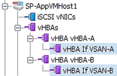
Each UCS server is equipped with a physical adapter or a Cisco Virtual Interface Card (VIC). Cisco VIC presents multiple vPCIe devices or virtual Network Interface Cards (vNIC) to each host that vSphere identifies as vmnics. The hosts are dual homed Fabric A and Fabric B for redundancy and load balancing. In this design, the following vNICs and virtual switches are used on each. The –A vNICs connect to unified fabric A and –B to unified fabric B.
· One vSwitch for in-band management (MGMT-A, MGMT-B). On the management cluster, this switch would be used for vCenter HA
· Second vSwitch for vMotion traffic with two vNICs (vMotion-A, vMotion-B)
· One vDS switch (SS-vDS) with two vNICs (vNIC-A, vNIC-B) for application VM traffic
The Cisco UCS B200 M4 and C220 M4 servers in this setup were equipped with Cisco VIC 1340 and VIC 1227 cards respectively.
The virtual networking within each ESXi host is shown in the figure below.
Figure 2 Cisco UCS Server Virtual Networking
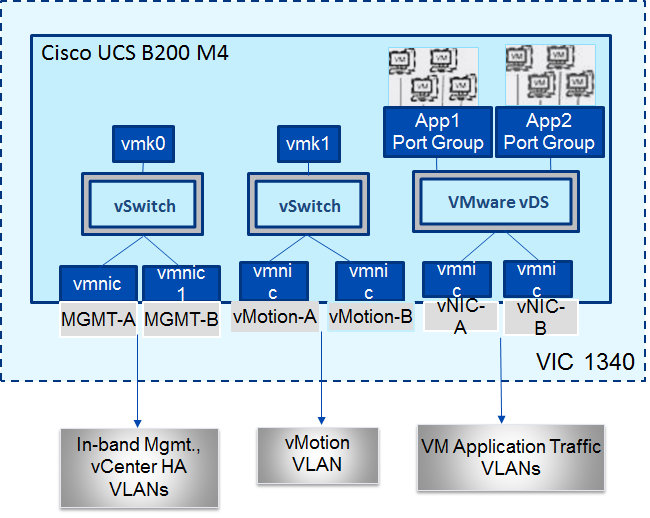
The Cisco-Nimble solution architecture uses two port groups (MGMT-PG) for in-band management and vMotion (vMOTION-PG) traffic with the following VMkernel NICs (vmk) for the following functionality:
· vmk0 - ESXi management
· vmk1 - vMotion interface
The ESXi management interface is for host to vCenter connectivity, direct access to ESXi shell and VMware cluster communication. The vMotion interfaces are private subnets supporting data access and VM migration across the Cisco-Nimble infrastructure. Additional port groups are created as needed for the Application traffic groups on VMware vDS switch.
Storage
The Unified Flash Fabric that provides the storage in this design uses Nimble Storage’s AF7000 all flash array and CS5000 adaptive flash array clustered together in a single group. Up to four all flash or adaptive flash arrays can be clustered together in the same group. Nondisruptive scale out provides increased performance and capacity and the ability to tier storage media within the same group.
Although specific array model numbers are used in this design, the validation is focused on the version of Nimble OS running on each array. Both all flash and adaptive flash arrays operate using the same Nimble OS build, which is the foundation of the Unified Flash Fabric. The common operation systems combined with a universal hardware architecture means that any array model number can be used in this design provided it operates with the validated Nimble OS version.
Each Nimble Storage controller contains redundant management ports, redundant power supplies, and the ability to add up to three I/O expansion cards. I/O expansion cards can be 16Gb FC or 10Gb Ethernet cards with options for 2 or 4 ports per card. Each array and expansion shelf contains 24 drive bays, with each bay accepting a single 3.5” HDD or a single Dual Flash Carrier (DFC) with two 2.5” SSDs that can be individually removed. Flash capacity expansion is a simple as adding additional drives to the existing array, or by attaching expansion shelves to the SAS 3.0 (12Gb) expansion ports. Additional HDD capacity expansion is possible by attaching expansion shelves. Adaptive flash arrays can add HDD or all flash expansion shelves.
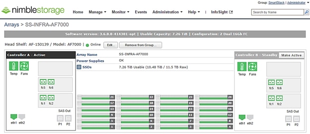
The AF7000 all flash array configuration used in this design contains 24 x 480GB SSDs for a total of 11.5TB raw flash capacity. Each controller (active and passive) contains 2 x 16Gb FC expansion cards for multiple redundant connections to each SAN fabric (Fabric A and Fabric B).
Figure 3 Nimble Storage AF7000 array configuration overview
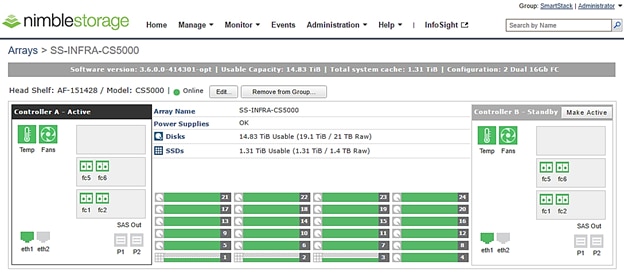
The CS5000 adaptive flash array configuration contains 3 x 480GB SSDs for flash cache with a total of 1.4TB raw flash capacity with another 21 x 1TB HDDs for a total of 21TB raw disk capacity. Each controller (active and passive) contains 2 x 16Gb FC expansion cards for multiple redundant connections to each SAN fabric (Fabric A and Fabric B).
Figure 4 Nimble Storage CS5000 adaptive flash array configuration overview
To optimize and model the required performance, the storage arrays and virtual machines are remotely monitored from the cloud using Nimble InfoSight™. This provides insight into data I/O patterns and capacity usage, and trend analysis for capacity planning and expansion. Also it allows for pro-active ticketing and notification when any issues occur. Providing this kind of deep level analytics into the data patterns and requirements, along with Nimble expandability allows an array to scale performance in exactly the desired area.
This design uses 16G fabric connectivity with two FC interface cards to provide 64G of FC bandwidth per controller. For additional FC bandwidth, a third FC card can be deployed on each controller but this interface is typically used for 10GbE connections to other arrays in a scale-out cluster for data replication traffic. The links between a pair of Cisco MDS and Fabric Interconnect switches are aggregated using 4x8G FC links to deliver 32G of bandwidth across the SAN fabric to each controller. Nimble Storage arrays support nondisruptive upgrades for adding additional capacity (scale deep), controller upgrades (scale up), or adding additional arrays (scale out).
The design uses FC SAN boot for the primary boot device of the Cisco UCS blades. The Service Profile used to configure and deploy Cisco UCS servers is configured to include a boot policy that points to the Nimble Storage arrays. The boot policy specifies a primary and secondary SAN paths to the two controllers (active and passive) on each array where the boot volumes reside. A second boot policy is also configured but with the primary and secondary paths reversed from that of the first boot profile. The second boot policy is used to load balance SAN boot across different paths when multiple servers are booting. This is an optional aspect of the design that can be helpful in larger deployments for distributing load when multiple servers have to be simultaneously booted. Each server has a dedicated boot volume (40GB) on the Nimble storage array. Nimble Storage arrays provide an Access Control List at the initiator level to only allow connections from the appropriate Cisco UCS blade. During the initial SAN boot, the server attaches to all primary and secondary connections to both active and standby controllers. This provides for normal boot operations even when a controller or primary path is offline. The hosts are configured with the Nimble Connection Manager and Path Selection Policy which optimize MPIO (multi-pathing) settings. This will allow for proper FC path management and failover connectivity with Nimble Storage volumes.
The following section of this document provides more details on the connectivity and high availability aspects of this design.
Networking
The LAN network provides network reachability to the applications hosted on Cisco UCS servers in the data center. The infrastructure consists of pair of Cisco Nexus 9372 PX switches deployed in NX-OS standalone mode. Two 10Gbps links from each Cisco Nexus switch are connected to a 10Gbps port on each FI to provide 20Gbps of uplink bandwidth through each Cisco Nexus switch. Virtual Port Channels (vPCs) are configured across these links to provide link and node redundancy while providing higher uplink bandwidth. VLAN trunking is enabled on these links as multiple application data, management and vMotion VLANs needs to traverse these links. Cisco recommended design practices are also implemented in this design – see Cisco Nexus 9000 best practices section of the Design Guide for details.
The SAN network provides fibre channel connectivity to the Nimble storage array and consists of a pair of Cisco MDS switches. The Cisco MDS switches form completely separate fabrics (SAN fabric A, SAN fabric B) and use a dual vSAN (vSAN-A, vSAN-B) design to provide two redundant and completely diverse paths to the Nimble Storage array.
Link aggregation using port channels are used to aggregate 4 x 8G FC links to provide 32G of FC bandwidth on each SAN Fabric between Cisco FI and Cisco MDS switches. Individual links are used by the Nimble array (link aggregation is unnecessary) with 2 links from each SAN fabric connected to both controllers to provide 32G of FC bandwidth to each controller (active and passive).
Cisco MDS switches are deployed with N-Port ID Virtualization (NPIV) enabled to support the virtualized environment running on Cisco UCS blade and rack servers. NPIV is necessary to provide isolation in virtualized environments where multiple virtual machines are running on a single server but a LUN needs to be presented to only one VM and not all VMs running on the server. Without NPIV, LUNs would be presented to the host and as a result, all VMs running on that host. To support NPIV on the Cisco UCS servers, the Cisco UCS Fabric Interconnects that connect the servers to the SAN fabric, are enabled for N-Port Virtualization (NPV) mode by configuring to operate in end-host mode (as opposed to FC switching mode). NPV enables Cisco FIs to proxy fabric login, registration and other messages from the servers to the SAN Fabric without being a part of the SAN fabric. This is important for keeping the limited number of Domain IDs that Fabric switches require to a minimum.
The design also uses jumbo frames with an MTU of 9216 Bytes across the LAN and Unified Fabric links. Jumbo frames increase the throughput between devices by enabling larger sized frames to be sent and received on the wire while reducing the CPU resources necessary to process them. Jumbo frames were enabled during validation on the LAN network links in the Cisco Nexus switching layer and on the Unified Fabric links.
Low-Level Design
Compute
To validate this design, a Cisco UCS with 4x Cisco B200M4 half-width blades and a Cisco C220 M4 rack mount server running VMware ESXi 6.5 were deployed in the POD to host application VMs. The servers were configured to be part of a cluster with VMware high availability enabled. The blade server chassis is connected to a pair of Cisco UCS 6248 FIs using a pair of Cisco 2208 XP fabric extenders located at the back of the chassis. Eight 10GbE links are used for FEX to FI connectivity, 4 from FEX-A to FI-A and 4 from FEX-B to FI-B to provide an aggregate access bandwidth of 80Gbps to the unified fabric.
The Fabric Interconnects in the design are deployed in End-host Ethernet switching mode. Ethernet switching mode determines how the fabric interconnects behave as switching devices between the servers and the network. End-host mode is the default and generally recommended mode of operation. In this mode, the fabric interconnects appear to the upstream LAN devices as end hosts with multiple adapters and do not run Spanning Tree. The Cisco Nexus switch ports that connect to the FI are therefore deployed as spanning tree edge ports.
The ports on the Cisco UCS 6248 FI are unified ports that can support either Ethernet or Fibre Channel traffic based by changing the port mode.
Ethernet ports on the fabric interconnects are not configured by default and must be explicitly configured as a specific type, which determines the port’s behavior. The port types used in this design are:
· Uplink ports for connecting to the Cisco Nexus 9300 series switches and external LAN network
· Fiber Channel ports for connecting to the SAN Fabric
· Server ports for connecting to external Cisco UCS C-series rack mount servers
Cisco UCS Manager (Cisco UCSM) is used to provision and manage Cisco UCS and its sub-components (chassis, FI, blade, and rack mount servers). Cisco UCSM runs on the Fabric Interconnects.
A key feature of Cisco UCSM is Service Profile Templates that enable the abstraction of policies, pools, and other aspects of a server configuration and consolidate it in the form of a template. The configuration in a service profile template includes:
· Server Identity (UUID Pool, Mac Address Pool, IP Pools etc.)
· Server Policies (BIOS Policy, Host Firmware Policy, Boot Policy etc.)
· LAN Configuration (VLAN, QoS, Jumbo Frames etc.)
· Storage Configuration (IQN pool)
The template once created, can be used to generate a service profile that configure and deploy individual server or group of servers. A service profile defines the server and its storage and networking characteristics. A service profile template reduces the deployment time, and increases the operational agility and provides general ease of deployment. Service profile templates are used in this design to rapidly configure and deploy multiple servers with minimal modification.
LAN Network
The LAN infrastructure design consists of a pair of Cisco Nexus 9372 PX switches. Each Cisco UCS FI connects to the switches using 2x10GbE links and the FI Ethernet ports used for this connectivity are configured as Uplink Ports. The uplinks ports are enabled for Link aggregation with FI-A uplinks in port channel 13, and the FI-B uplink ports in port channel 14. The uplinks ports are connected to different Cisco Nexus switches and configured to be part of a virtual PortChannel (vPC) on the Cisco Nexus switches. vPC 13 connects Cisco Nexus A to FI-A and FI-B and vPC 14 connects Cisco Nexus B to FI-A and FI-B. The Cisco Nexus vPC feature allows a device to aggregate links going to different Cisco Nexus switches. As a result, the uplink ports appear as a regular PortChannel to Cisco UCS. Link aggregation, spanning tree and other configuration parameters between Cisco UCS and Cisco Nexus switches follow Cisco recommended best practices – see Design Guide associated with this document for more details.
Multiple VLANs need to traverse the uplink ports and uplink ports are automatically configured as IEEE 802.1Q trunks for all VLANs defined on the fabric interconnect. VLANs for management, vMotion, and applications traffic are defined in the fabric interconnects and enabled on the uplinks. The VLANs used in validating the design are summarized in the table below.
Table 1 Uplink VLANs Trunked From Cisco UCS to Cisco Nexus
| VLAN Type |
VLAN ID |
Description |
| Native VLAN |
2 |
Untagged VLAN Traffic are forwarded on this VLAN |
| In-Band Management |
12 |
VLAN used for in-band management, including ESXi hosts and Infrastructure VMs |
| vMotion |
3000 |
VLAN used by ESXi for moving VMs between hosts. vMotion uses management VLAN |
| vCenter HA Network |
3001 |
VLAN used by vCENTER HA network for HA traffic between Active, Passive and Witness vCenter nodes. (Only used in the Management POD) |
| VM Application Traffic |
950, 951 |
VLAN used by Application Data Traffic |
The detailed deployment procedures for configuring Cisco UCS and Cisco Nexus switches are provided in the Deployment section of this document.
SAN Fabric and Storage
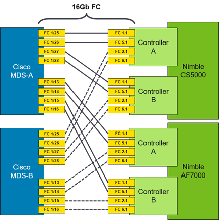
FC Cisco MDS Switch to Nimble Storage Array Connectivity
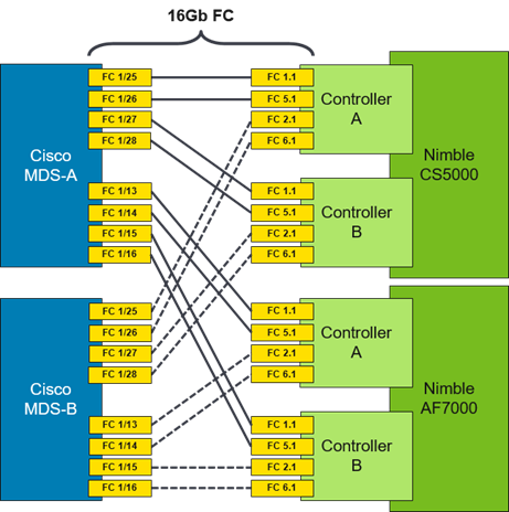
This design uses a dual Fabric, each its own VSAN configuration which allows for two diverse paths for FC connectivity. In this example ports FC1/13-16 (AF7000) and FC1/25-28 (CS5000) are the Nimble Storage target ports. The connections on the Nimble Storage must mirror each other (i.e. FC 1.1 and FC 5.1 from each controller connect to MDS-A while FC 2.1 and FC 6.1 from each controller connect to MDS-B).
Figure 5 Cisco MDS to Nimble Storage array connectivity diagram
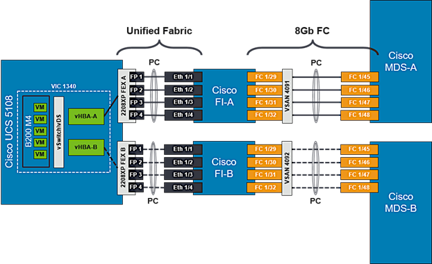
FC Cisco MDS Switch to Cisco UCS Fabric Interconnect Topology
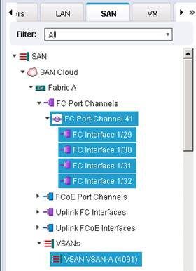
On both Cisco MDS switches, Ports FC1/45-48 is part of a FC port-channel that connects to Fabric Interconnect ports FC1/29-32. FC port-channel 41 connects Fabric Interconnect A to MDS-A and FC port-channel 42 connects Fabric Interconnect B to MDS-B. By default, both MDS and FI from Cisco UCSM, VSANs 4091 needs to be created in SAN tab > SAN Cloud > Fabric A. The FC port channel needs to be defined for the ports connected to the Cisco MDS-A (for example, 29-32).
Figure 6 Cisco UCS Servers to Cisco UCS Fabric Interconnect Connectivity Diagram
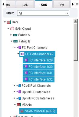
Also, VSANs 4092 needs to be created in SAN tab > SAN Cloud > Fabric B. The FC port channel needs to be defined for the ports connected to the Cisco MDS-A (for example, 29 - 32). When complete you get a similar screen as shown below.
Cisco MDS Switch Fabric Configuration
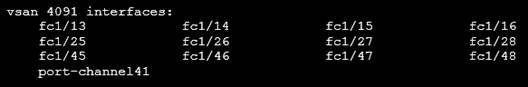
Cisco MDS-A Switch VSAN requires that a port channel be created to the corresponding ports on Fabric Interconnect A ports (FC1/45-48). The port channel should match the configuration on the Cisco UCS Fabric Interconnect (41). Note that VSAN membership is required for physical ports and the port-channel. Additionally, confirm that the VSAN for the Nimble FC ports are part of the same VSAN (4091).
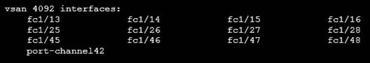
Cisco MDS-B Switch VSAN requires that a port channel be created to the corresponding ports on Fabric Interconnect B ports (FC1/45-48). The port channel should match the configuration on the Cisco UCS Fabric Interconnect (42). Note that VSAN membership is required for the physical ports and the port-channel. Additionally, confirm that the VSAN for the Nimble FC ports are part of the same VSAN (4092).
For further security and traffic isolation, the zoning design allows a single initiator to access multiple target ports. Note that both the Active and Standby target ports are configured in the same zone.
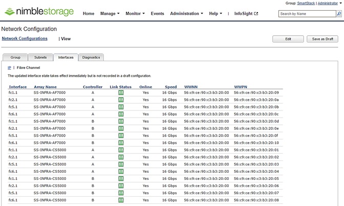
Figure 7 Nimble Storage AF7000 and CS5000 WWPN Target Ports
Cisco MDS-A Zoning Configuration
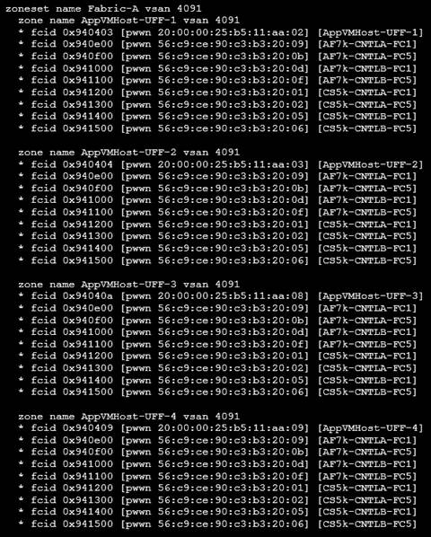
Cisco MDS-B Zoning Configuration
Cisco UCS Fabric Interconnect VSAN Configuration
Table 2 Storage VSANs between Cisco UCS and Nimble
| VSAN Type |
VSAN ID |
Description |
| FC Path A |
4091 |
VSAN used for FC traffic on Fabric A. This VSAN exists only on Fabric A. |
| FC Path B |
4092 |
VSAN used for FC traffic on Fabric B. This VSAN exists only on Fabric B. |
For the host side configuration, a single WWNN and dual WWPN configuration was used for the two independent FC paths as identified below.
Table 3 FC Deployment Information
| WWNN Pool |
20:00:00:25:B5:11:11:00- 20:00:00:25:B5:11:11:1F |
| WWPN Pool-A |
20:00:00:25:B5:11:AA:00- 20:00:00:25:B5:11:AA:7F |
| WWPN Pool-B |
20:00:00:25:B5:11:BB:00- 20:00:00:25:B5:11:BB:7F |
Cisco UCS Service Profile Considerations
Each ESXi Service Profile host is configured with two fabric diverse vHBAs to allow connectivity into VSAN-A and VSAN-B.
SAN Boot
Each Cisco UCS blade was deployed using FC SAN boot. Using SAN boot affords the advantages of Nimble snapshot, recovery, replication, and cloning mechanisms.
This design has each Cisco UCS blade utilizing two vHBAs that have a presence into diverse fabrics. Each blade had a boot volume created on the Nimble Storage array. The Nimble Storage array provides an initiator group to only honor connections from this single service profile. During FC SAN boot connectivity, the blade connects to both primary and secondary WWPN target for the both active and standby controllers. This provides for normal boot operations regardless of which Nimble Storage Controller is active. The host software utilized MPIO and the Nimble Connection Manager assisted with FC path management. Also, the VMware hosts in question were deployed in a cluster to allow for HA failover and to avoid a single point of failure at the hypervisor layer.
Host Storage MPIO Considerations
The VMware ESXi host is configured to use the NIMBLE_PSP_DIRECTED path policy from the Nimble Connection Manager. See “Setting up Nimble Connection Manager” section for the detailed procedures on installing and configuring Nimble’s multipathing policy. For this design, 4 paths will be in Active (I/O) running state and 4 paths in Standby.
The table below is a summary of all the components used in this design.
Table 4 Infrastructure Components and Software Revisions
|
|
Components |
Software Version |
Comments |
| Network |
Cisco Nexus 9372 PX x 2 |
7.0(3)I2(4)
|
NX-OS Standalone mode; Provides connectivity to Enterprise LAN and users |
|
|
Cisco UCS 6248 UP Fabric Interconnects x 2 |
3.1.2(b) |
|
|
|
Cisco MDS 9148S x 2 |
7.3(0)DY1 |
16G Multilayer FC Switch |
| Compute |
Cisco UCS 5108 Blade Server Chassis |
3.1.2(b) |
|
|
|
Cisco UCS B200 M4 servers x 2 |
3.1.2(b) |
|
|
|
Cisco UCS C220 M4 server x 1 |
3.1.2(b) |
|
|
|
ENIC Driver |
1.0.0.2 |
Ethernet driver for Cisco VIC |
|
|
Cisco FNIC driver |
1.6.0.28 |
FCoE driver for Cisco VIC |
|
|
Adapter Firmware |
4.1(2) |
Cisco VIC Adapter Firmware |
| Management |
Cisco UCS Manager |
3.1(2b) |
|
|
|
vCenter plugin for Nimble |
|
|
| Storage |
Nimble Storage AF7000 All Flash Array |
NimbleOS 3.6.0.0 GA |
Build: 3.6.0.0-414301-opt |
|
|
Nimble Storage CS5000 Adaptive Flash Array |
NimbleOS 3.6.0.0 GA |
Build: 3.6.0.0-414301-opt |
|
|
Nimble Connection Manager (NCM) for ESXi |
3.4.0 |
Build: 3.4.0-650005 |
|
|
Nimble Windows Toolkit (NWT) |
3.2.0.410 |
|
| Virtualization |
VMware vSphere |
6.5 |
Build: 6.5.0-4564106 |
|
|
VMware vCenter Server Appliance |
6.5 |
Build: 6.5.0-4602587 |
| Tools |
Workload – IOMeter Tool |
|
|
| Other |
Microsoft Active Directory/DNS |
|
|
Cisco Nexus Configuration Workflow
Figure 8 Cisco Nexus 9000 Configuration Workflow
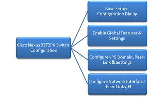
Base Setup – Configuration Dialog
This section outlines the base setup of Nexus 9000 switches using the configuration dialog.
Cisco Nexus A
To set up the initial configuration for the first Cisco Nexus switch complete the following steps:
1. Connect to the serial or console port of the switch
Enter the configuration method: console
Abort Auto Provisioning and continue with normal setup?(yes/no[n]:y
---- System Admin Account Setup ----
Do you want to enforce secure password standard (yes/no[y]:
Enter the password for "admin":
Confirm the password for "admin":
---- Basic System Configuration Dialog VDC: 1 ----
This setup utility will guide you through the basic configuration of the system. Setup configures only enough connectivity for management of the system.
Please register Cisco Nexus9000 Family devices promptly with your supplier. Failure to register may affect response times for initial service calls. Nexus9000 devices must be registered to receive entitled support services.
Press Enter at anytime to skip a dialog. Use ctrl-c at anytime to skip the remaining dialogs.
Would you like to enter the basic configuration dialog (yes/no): y
Create another login account (yes/no) [n]: n
Configure read-only SNMP community string (yes/no) [n]:
Configure read-write SNMP community string (yes/no) [n]:
Enter the switch name: D01-n9k1
Continue with Out-of-band (mgmt0) management configuration? (yes/no) [y]:
Mgmt0 IPv4 address: 192.168.155.3
Mgmt0 IPv4 netmask: 255.255.255.0
Configure the default gateway? (yes/no) [y]:
IPv4 address of the default gateway: 192.168.155.1
Configure advanced IP options? (yes/no) [n]:
Enable the telnet service? (yes/no) [n]:
Enable the ssh service? (yes/no) [y]:
Type of ssh key you would like to generate (dsa/rsa) [rsa]:
Number of rsa key bits <1024-2048> [1024]: 2048
Configure the ntp server? (yes/no) [n]: y
NTP server IPv4 address: 192.168.155.254
Configure default interface layer (L3/L2) [L2]:
Configure default switchport interface state (shut/no shut) [no shut]:
Configure CoPP system profile (strict/moderate/lenient/dense/skip) [strict]:
2. Review the settings printed to the console. If they are correct, answer yes to apply and save the configuration
3. Wait for the login prompt to make sure that the configuration has been saved prior to proceeding.
Cisco Nexus B
To set up the initial configuration for the second Cisco Nexus switch complete the following steps:
1. Connect to the serial or console port of the switch
2. The Cisco Nexus B switch should present a configuration dialog identical to that of Cisco Nexus A shown above. Provide the configuration parameters specific to Cisco Nexus B for the following configuration variables. All other parameters should be identical to that of Cisco Nexus A.
· Admin password
· Nexus B Hostname: D01-n9k2
· Nexus B mgmt0 IP address: 192.168.155.4
· Nexus B mgmt0 Netmask: 255.255.255.0
· Nexus B mgmt0 Default Gateway: 192.168.155.1
In the next section we look at the configuration required on the Cisco Nexus Switches for LAN and management connectivity.
Enabling Global Features and Settings
On both Cisco Nexus switches, enable the following features and best practices.
feature nxapi
feature udld
feature interface-vlan
feature lacp
feature vpc
spanning-tree port type edge bpduguard default
spanning-tree port type edge bpdufilter default
port-channel load-balance src-dst ip-l4port-vlan
Create VLANs
Create the vlans used in this solution.
vlan 12
name IB-MGMT
vlan 2
name Native-VLAN
vlan 950
name APP1
vlan 951
name APP2
vlan 3000
name vMotion
Configure vPC Domain, Peer-Link and Settings
Cisco Nexus A
To configure virtual port channels (vPCs) for switch A, complete the following steps:
1. From the global configuration mode, create a new vPC domain:
vpc domain 155
2. Make Cisco Nexus A the primary vPC peer by defining a low priority value:
role priority 10
3. Use the management interfaces on the supervisors of the Cisco Nexus switches to establish a keepalive link:
peer-keepalive destination 192.168.155.4 source 192.168.155.3
4. Enable following features for this vPC domain:
peer-switch
delay restore 150
peer-gateway
ip arp synchronize
auto-recovery
5. Save the configuration:
copy run start
Cisco Nexus B
To configure vPCs for switch B, complete the following steps:
1. From the global configuration mode, create a new vPC domain:
vpc domain 155
2. Make Cisco Nexus A the primary vPC peer by defining a higher priority value on this switch:
role priority 20
3. Use the management interfaces on the supervisors of the Cisco Nexus switches to establish a keepalive link:
peer-keepalive destination 192.168.155.3 source 192.168.155.4
4. Enable following features for this vPC domain:
peer-switch
delay restore 150
peer-gateway
ip arp synchronize
auto-recovery
5. Save the configuration:
copy run start
Configure Network Interfaces for VPC Peer Links
Cisco Nexus A
1. Define a port description for the interfaces connecting to VPC Peer D01-n9k2.
interface Eth1/53
description VPC Peer D01-n9k2:e1/53
interface Eth1/54
description VPC Peer D01-n9k2:e1/54
2. Apply a port channel to both VPC Peer links and bring up the interfaces.
interface Eth1/53,Eth1/54
channel-group 155 mode active
no shutdown
3. Enable UDLD on both interfaces to detect unidirectional links.
udld enable
4. Define a description for the port-channel connecting to D01-n9k2.
interface port-channel 155
description vPC peer-link
5. Make the port-channel a switchport, and configure a trunk to allow in-band management, VM traffic, and the native VLAN.
switchport
switchport mode trunk
switchport trunk native vlan 2
switchport trunk allowed vlan 12, 950, 951
spanning-tree port type network
6. Make this port-channel the VPC peer link and bring it up.
vpc peer-link
no shutdown
copy run start
Cisco Nexus B
1. Define a port description for the interfaces connecting to VPC Peer D01-n9k1.
interface Eth1/53
description VPC Peer D01-n9k1:e1/53
interface Eth1/54
description VPC Peer D01-n9k1:e1/54
2. Apply a port channel to both VPC Peer links and bring up the interfaces.
interface Eth1/53,Eth1/54
channel-group 155 mode active
no shutdown
3. Enable UDLD on both interfaces to detect unidirectional links.
udld enable
4. Define a description for the port-channel connecting to D01-n9k1.
interface port-channel 155
description vPC peer-link
5. Make the port-channel a switchport, and configure a trunk to allow in-band management, VM traffic, and the native VLAN.
switchport mode trunk
switchport trunk native vlan 2
switchport trunk allowed vlan 12, 950-951, 3000
spanning-tree port type network
6. Make this port-channel the VPC peer link and bring it up.
vpc peer-link
no shutdown
copy run start
Configure Network Interfaces to Cisco UCS Fabric Interconnects
Cisco Nexus A
1. Define a description for the port-channel connecting to D01-FI-A.
interface port-channel 13
description D01-FI-A
2. Make the port-channel a switchport, and configure a trunk to allow in-band management, VM traffic, and the native VLANs.
switchport mode trunk
switchport trunk native vlan 2
switchport trunk allowed vlan 12, 950-951, 3000
3. Make the port channel and associated interfaces spanning tree edge ports.
spanning-tree port type edge trunk
spanning-tree guard root
no lacp graceful-convergence
mtu 9216
4. Make this a VPC port-channel and bring it up.
vpc 13
no shutdown
5. Define a port description for the interface connecting to D01-FI-A.
interface Eth1/23
description D01-FI-A:p15
6. Apply it to a port channel and bring up the interface.
channel-group 13 mode active
no shutdown
7. Enable UDLD to detect unidirectional links.
udld enable
8. Define a description for the port-channel connecting to D01-FI-B.
interface port-channel 14
description D01-FI-B
9. Make the port-channel a switchport, and configure a trunk to allow in-band management, VM traffic VLANs and the native VLAN.
switchport mode trunk
switchport trunk native vlan 2
switchport trunk allowed vlan 12, 950-951, 3000
10. Make the port channel and associated interfaces spanning tree edge ports.
spanning-tree port type edge trunk
spanning-tree guard root
no lacp graceful-convergence
mtu 9216
11. Make this a VPC port-channel and bring it up.
vpc 14
no shutdown
12. Define a port description for the interface connecting to D01-FI-B
interface Eth1/24
description D01-FI-B:p15
13. Apply it to a port channel and bring up the interface.
channel-group 14 mode active
no shutdown
14. Enable UDLD to detect unidirectional links.
udld enable
copy run start
Cisco Nexus B
1. Define a description for the port-channel connecting to D01-FI-A.
interface port-channel 13
description D01-FI-B
2. Make the port-channel a switchport, and configure a trunk to allow in-band management, VM traffic, and the native VLANs.
switchport mode trunk
switchport trunk native vlan 2
switchport trunk allowed vlan 12, 950-951, 3000
3. Make the port channel and associated interfaces spanning tree edge ports.
spanning-tree port type edge trunk
spanning-tree guard root
no lacp graceful-convergence
mtu 9216
4. Make this a VPC port-channel and bring it up.
vpc 13
no shutdown
5. Define a port description for the interface connecting to D01-FI-A
interface Eth1/23
description D01-FI-A:p2
6. Apply it to a port channel and bring up the interface.
channel-group 13 mode active
no shutdown
7. Enable UDLD to detect unidirectional links.
udld enable
8. Define a description for the port-channel connecting to D01-FI-B
interface port-channel 14
description D01-FI-B
9. Make the port-channel a switchport, and configure a trunk to allow in-band management, and VM traffic VLANs and the native VLAN.
switchport mode trunk
switchport trunk native vlan 2
switchport trunk allowed vlan 12, 950-951, 3000
10. Make the port channel and associated interfaces spanning tree edge ports.
spanning-tree port type edge trunk
spanning-tree guard root
no lacp graceful-convergence
mtu 9216
11. Make this a VPC port-channel and bring it up.
vpc 14
no shutdown
12. Define a port description for the interface connecting to D01-FI-B
interface Eth1/24
description D01-FI-A:p2
13. Apply it to a port channel and bring up the interface.
channel-group 14 mode active
no shutdown
14. Enable UDLD to detect unidirectional links.
udld enable
copy run start
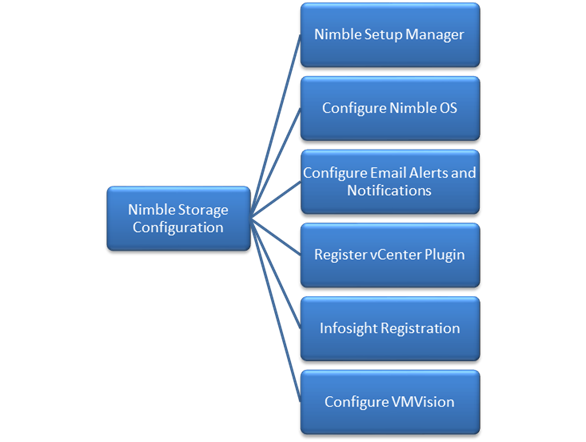
This section provides the procedure for initializing a Nimble Storage array and setting up basic IP connectivity. Note, that the dialog below is specific for an FC array setup.
Nimble Storage Configuration Workflow
Figure 9 Nimble Storage Configuration Workflow
Base Setup of Nimble Storage Array
Nimble Setup Manager
The steps discussed in this section apply to setting up both an all flash and adaptive flash array (as they both run the same OS and distribution). The Nimble Setup manager is part of the Nimble Storage Windows Toolkit. In this section, the Nimble Setup Manager is the only component that needs to be installed. The Nimble Setup manager is used to do the initial setup of the array and can be downloaded from Infosight at this location: https://infosight.nimblestorage.com/InfoSight/media/software/active/1/103/Setup-NimbleNWT-x64.3.4.0.2.zip
![]() The version of the setup manager used must be same or higher than the version of NimbleOS being deployed. Always check InfoSight to see all of the currently available versions of the Windows Toolkit.
The version of the setup manager used must be same or higher than the version of NimbleOS being deployed. Always check InfoSight to see all of the currently available versions of the Windows Toolkit.
Initialize Nimble Storage Array
1. In the Windows Start menu, click Nimble Storage > Nimble Setup Manager.
2. Select one of the uninitialized arrays from the Nimble Setup Manager list and click Next.
![]() If the array is not visible in Nimble Setup Manager, verify that the array’s eth1 ports of both controllers are on the same subnet as the Windows host.
If the array is not visible in Nimble Setup Manager, verify that the array’s eth1 ports of both controllers are on the same subnet as the Windows host.
Configure Nimble OS using the GUI
1. Choose the appropriate group option and click Next.
a. Set up the array but do not join a group. Continue to Step 5.
b. Add the array to an existing group.
![]() If you chose to join an existing group, your browser automatically redirects to the login screen of the group leader array. See Add Array to Group Using the GUI to complete the configuration.
If you chose to join an existing group, your browser automatically redirects to the login screen of the group leader array. See Add Array to Group Using the GUI to complete the configuration.
2. Provide or change the following initial management settings and click Finish:
· Array name
· Group name
· Management IP address and subnet mask for the eth1 interface
· Default gateway IP address
· Optional. Administrator password
3. You may see a warning similar to “There is a problem with this website's security certificate”. It is safe to ignore this warning and click Continue.
![]() If prompted, you can also download and accept the certificate. Alternatively, create your own. See the cert command in the Nimble Command Line Reference Guide. Also, if Internet Explorer v7 displays a blank page, clear the browser's cache. The page should be visible after refreshing the browser.
If prompted, you can also download and accept the certificate. Alternatively, create your own. See the cert command in the Nimble Command Line Reference Guide. Also, if Internet Explorer v7 displays a blank page, clear the browser's cache. The page should be visible after refreshing the browser.
4. In the login screen, type the password you set and click Log In. From this point forward, you are in the Nimble OS GUI. The first time you access the Nimble OS GUI, the Nimble Storage License Agreement appears.
5. In the Nimble Storage License Agreement, read the agreement, scroll to the bottom, check the acknowledgment box, and then click Proceed.
6. Provide the Subnet Configuration information for the following sections and click Next:
a. Management IP: IP address, Network and Subnet Mask.
![]() The Management IP is used for the GUI, CLI, and replication. It resides on the management subnet and floats across all "Mgmt only" and "Mgmt + Data" interfaces on that subnet. Note: in this instance you only need to configure the Management network. No IP data network connectivity is required.
The Management IP is used for the GUI, CLI, and replication. It resides on the management subnet and floats across all "Mgmt only" and "Mgmt + Data" interfaces on that subnet. Note: in this instance you only need to configure the Management network. No IP data network connectivity is required.
b. Subnet: Subnet label, Network, Netmask, Traffic Type(Data only, Mgmt Only, Mgmt +Data), MTU.
7. Maximum Transmission Unit (MTU) – Standard (1500) Provide Interface Assignment information for the following sections and click Next:
a. Interface Assignment: For each IP interface, assign it a subnet and a Data IP address within the specified network. For inactive interface, assign the "None" subnet.
b. Diagnostics:
i. Controller A diagnostics IP address will be on the same subnet as the management IP address.
ii. Controller B diagnostics IP address will be on the same subnet as the management IP address.
8. Provide the following Domain information and click Next:
a. Domain Name
b. DNS Servers: Type the hostname or IP address of your DNS server. You can list up to five servers.
9. Provide the following Time information and click Next:
a. Time Zone: Choose the time zone the array is located in.
b. Time (NTP) Server: Type the hostname or IP address of your NTP server.
10. Provide Support information for the following sections and click Finish.
11. Email Alerts:
a. From Address: This is the email address used by the array when sending email alerts. It does not need to be a real email address. Include the array name for easy identification.
b. Send to Address: Nimble recommends that you check the Send event data to Nimble Storage Support check box.
c. SMTP server hostname or IP address
d. AutoSupport:
i. Checking the Send AutoSupport data to Nimble Storage check box enables Nimble Storage Support to monitor your array, notify you of problems, and provide solutions.
ii. HTTP Proxy: AutoSupport and software updates require an HTTPS connection to the Internet, either directly or through a proxy server. If a proxy server is required, check the Use HTTP Proxy check box and provide the following information to configure proxy server details:
iii. HTTP proxy server hostname or IP address
iv. HTTP proxy server port
v. Proxy server user name
vi. Proxy server password
![]() The system does not test the validity of the SMTP server connection or the email addresses that you provided.
The system does not test the validity of the SMTP server connection or the email addresses that you provided.
12. Click Finish. The Setup Complete screen appears. Click Continue.
13. The Nimble OS home screen appears. Nimble Storage array setup is complete.
Configure Array to Send Email Notifications for Alerts (Optional)
To setup email notification of events from the Nimble Storage array, complete the following steps. This is an optional setup but highly recommended.
1. On the Wellness page, click Daily Summary Emails.
2. Check Subscribe to daily summary email.
3. Enter an email address for delivery of the email alerts.
4. (Optional) You can click Test to send a test email to the email address that you indicated.
5. Click Submit to conclude the email alerts setup.
Setup Nimble Management Tools
vCenter Plugin
The vCenter plugin from Nimble Storage allows for single pane of glass administration directly from vCenter as well as integration with Nimble Infosight analytics. Nimble Storage has integration to vCenter through plugin registration. This allows for datastore creation and management using vCenter. The vCenter plugin is supported on ESX 5.5 update 1 and later.
![]() The plugin is not supported for:
The plugin is not supported for:
- Multiple datastores located on one LUN
- One datastore spanning multiple LUNs
- LUNs located on a non-Nimble Storage array
For additional info, refer Nimble Storage VMware integration guide: https://infosight.nimblestorage.com/InfoSight/media/cms/active/pubs_VMware_Integration_Guide_aik1472500839218.ditamap.pdf
The procedure for registering the plugin are covered in the later section titled “Register the vCenter Plugin Using the NimbleOS CLI”.
InfoSight
Register and Log into InfoSight
To register and login to InfoSight, complete the following steps.
![]() It can take up to 24 hours for the array to appear in InfoSight after the first data set is sent. Data sets are configured to be sent around midnight array local time. Changes made right after the data set is sent at midnight might not be reflected in InfoSight for up to 48 hours.
It can take up to 24 hours for the array to appear in InfoSight after the first data set is sent. Data sets are configured to be sent around midnight array local time. Changes made right after the data set is sent at midnight might not be reflected in InfoSight for up to 48 hours.
1. Log in to the InfoSight portal at https://infosight.nimblestorage.com.
2. Click Enroll now to activate your account. If your email is not already registered, contact your InfoSight Administrator. If there is no existing, InfoSight Administrator (Super User) registered against your account or you are not sure, contact Nimble Storage Support for assistance.
3. Select the appropriate InfoSight role and enter the array serial number for your customer account. If this is the first account being created for your organization, you should select the Super User role. The number of super users is limited to the total number of arrays that are associated with an account.
4. Click Submit.
5. A temporary password is sent to the email address that you specified. You must change your password the first time you log in.
Configure Array to Send Data to InfoSight
To take full advantage of the InfoSight monitoring and analysis capabilities, configure your Nimble arrays to send data sets, statistics, and events to Nimble Storage Support. InfoSight recommendations and automatic fault detection are based on InfoSight processing the data from your arrays. If you do not configure the arrays to send this data to Nimble Storage Support during the initial setup, you can change the configuration at any time from the Administration menu in the GUI.
To configure the array to send data to InfoSight, complete the following steps.
1. From the Administration menu in the array GUI, select Alerts and Monitoring > AutoSupport / HTTP Proxy.
2. On the AutoSupport page, select Send AutoSupport data to Nimble Storage Support.
3. Click Test AutoSupport Settings to confirm that AutoSupport is set up correctly.
4. Click Save.
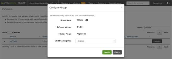
Configure Arrays to Monitor VMware Environment using VMVision
VMVision is part of InfoSight and provides visibility into the entire virtualization stack. It provides agentless per-VM monitoring and statistics. VMVision provides visibility into VMs with the most I/O churn and resource constraints. For additional info on VMVision, refer: http://uploads.nimblestorage.com/wp-content/uploads/2015/07/12132211/nimblestorage-vmvision.pdf
In order to monitor your VMware environment using VMVision, the following steps must be completed.
· Register the vCenter plugin with each vCenter from each Nimble Array groups
· Enable streaming of performance data to InfoSight.
To verify the vCenter plugin registration completed in earlier step and enabled streaming of performance data, complete the following steps for each array individually if ungrouped, or one time for a group of arrays.
1. Log in to https://infosight.nimblestorage.com
2. Go to Administration > VMVision.
3. In the VMVision list, find the array group to monitor.
4. Verify that your software version is up to date and vCenter plugin is registered.
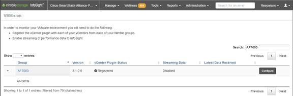
5. Click Configure. In the Configure Group dialog box that opens, select Enabled in the VM Streaming Data list and Click Update.
This section provides detailed procedures for deploying and configuring Cisco MDS switches used in this solution for SAN connectivity.
Cisco MDS Configuration Workflow
Figure 10 Cisco MDS Configuration Workflow
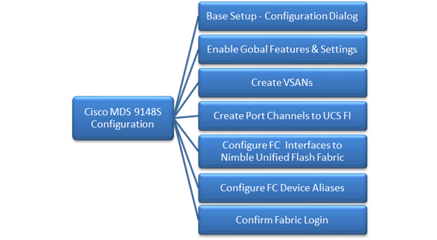
Base Setup using Configuration Dialog
This section provides details on the initial setup of Cisco MDS Fibre Channel Switches. Two switches, Cisco MDS-A and Cisco MDS-B are deployed to provide redundancy in the event of a switch failure.
Cisco MDS A
To set up the initial configuration for the first Cisco MDS switch complete the following steps:
![]() On initial boot, connect to the serial or console port of the switch and the switch should automatically start and attempt to enter Power ON Auto Provisioning.
On initial boot, connect to the serial or console port of the switch and the switch should automatically start and attempt to enter Power ON Auto Provisioning.
1. Connect to the serial or console port of the switch
Abort Auto Provisioning and continue with normal setup? (yes/no)[n]: y
---- System Admin Account Setup ----
Do you want to enforce secure password standard (yes/no) [y]:
Enter the password for "admin":
Confirm the password for "admin":
---- Basic System Configuration Dialog ----
This setup utility will guide you through the basic configuration of
the system. Setup configures only enough connectivity for management of the system.
Please register Cisco MDS 9000 Family devices promptly with your supplier. Failure to register may affect response times for initial service calls. MDS devices must be registered to receive entitled support services.
Press Enter at anytime to skip a dialog. Use ctrl-c at anytime to skip the remaining dialogs.
Would you like to enter the basic configuration dialog (yes/no): y
Create another login account (yes/no) [n]:
Configure read-only SNMP community string (yes/no) [n]:
Configure read-write SNMP community string (yes/no) [n]:
Enter the switch name: D01-MDS-A
Continue with Out-of-band (mgmt0) management configuration? (yes/no) [y]:
Mgmt0 IPv4 address: 192.168.155.6
Mgmt0 IPv4 netmask: 255.255.255.0
Configure the default gateway? (yes/no) [y]:
IPv4 address of the default gateway: 192.168.155.1
Configure advanced IP options? (yes/no) [n]:
Enable the ssh service? (yes/no) [y]:
Type of ssh key you would like to generate (dsa/rsa) [rsa]:
Number of rsa key bits <1024-2048> [1024]: 2048
Enable the telnet service? (yes/no) [n]:
Configure congestion/no credit drop for fc interfaces? (yes/no[y]: Enter the type of drop to configure congestion/no_credit drop? (con/no) [c]:
Enter milliseconds in multiples of 10 for congestion-drop for port mode F in range (<100-500>/default), where default is 500. [d]:
Congestion-drop for port mode E must be greater than or equal to Congestion-drop for port mode F. Hence, Congestion drop for port mode E will be set as default.
Enable the http-server? (yes/no) [y]:
Configure clock? (yes/no) [n]:
Configure timezone? (yes/no) [n]: y
Enter timezone config [PST/MST/CST/EST]: EST
Enter Hrs offset from UTC [-23:+23]: -5
Enter Minutes offset from UTC [0-59]:
Configure summertime? (yes/no) [n]:
Configure the ntp server? (yes/no) [n]: y
NTP server IPv4 address: 192.168.155.254
Configure default switchport interface state (shut/noshut) [shut]:
Configure default switchport trunk mode (on/off/auto) [on]:
Configure default switchport port mode F (yes/no) [n]:
Configure default zone policy (permit/deny) [deny]:
Enable full zoneset distribution? (yes/no) [n]:
Configure default zone mode (basic/enhanced) [basic]:
2. Review the settings printed to the console. If they are correct, answer yes to apply and save the configuration
3. Wait for the login prompt to make sure that the configuration has been saved prior to proceeding.
Cisco MDS B
To set up the initial configuration for the second Cisco MDS switch complete the following steps:
![]() On initial boot and connection to the serial or console port of the switch, the NX-OS setup should automatically start and attempt to enter Power on Auto Provisioning.
On initial boot and connection to the serial or console port of the switch, the NX-OS setup should automatically start and attempt to enter Power on Auto Provisioning.
1. On initial boot, connect to the serial or console port of the switch.
2. The Cisco Nexus B switch should present a configuration dialog identical to that of Cisco Nexus A shown above. Provide the configuration parameters specific to Cisco Nexus B for the following configuration variables. All other parameters should be identical to that of Cisco Nexus A.
· Admin password
· MDS B Hostname: D01-MDS-B
· MDS B mgmt0 IP address: 192.168.155.7
· MDS B mgmt0 Netmask: 255.255.255.0
· MDS B mgmt0 Default Gateway: 192.168.155.1
· Timezone: EST
· Offset from UTC: -5
· NTP Server IP: 192.168.155.254
Enable Global Features and Settings
The following features should be enabled globally on both Cisco MDS switches from configuration mode.
feature npiv
feature fport-channel-trunk
Create VSANs
One VSAN per fabric is used in this design – VSAN 4091 on Cisco MDS-A and VSAN 4092 on Cisco MDS-B. Configure VSAN one each switch as follows.
Cisco MDS-A
vsan database
vsan 4091
Cisco MDS-B
vsan database
vsan 4092
Create Port Channels to Cisco UCS Fabric Interconnects
Each FI has a port channel link to one of the Cisco MDS switches for storage traffic. The port channel in this design has 4 links and is configured as follows.
Cisco MDS-A
1. Create the port channel to D01-FI-A.
interface port-channel 41
channel mode active
switchport rate-mode dedicated
2. Assign interfaces to the port channel.
interface fc1/45 – 48
port-license acquire
channel-group 41 force
no shutdown
3. Add port channel to VSAN in the VSAN database.
vsan database
vsan 4091 interface port-channel41
4. Save the configuration.
copy run start
Cisco MDS-B
1. Create the port channel to D01-FI-B.
interface port-channel 42
channel mode active
switchport rate-mode dedicated
2. Assign interfaces to the port channel.
interface fc1/45 – 48
port-license acquire
channel-group 42 force
no shutdown
3. Add port channel to VSAN in the VSAN database.
vsan database
vsan 4092 interface port-channel42
4. Save the configuration.
copy run start
Configure FC Interfaces to Unified Flash Fabric
Each MDS switch has four links to each Nimble array in the cluster, two links to Controller A and two to Controller B. This design uses 16G FC connectivity between Cisco MDS switches and Nimble arrays as the interfaces on both ends support 16G FC.
The detailed SAN Fabric connectivity to the Nimble Storage AF7000 all flash and CS5000 adaptive flash arrays used in this setup is shown in the figure below.
Figure 11 Figure 3 SAN Connectivity to Nimble Storage Arrays
Cisco MDS-A
1. Configure the speed and license for the ports connected to the AF7000 all flash array.
interface fc1/13-16
port-license acquire
no shutdown
2. Configure the speed and license for the ports connected to the CS5000 adaptive flash array.
interface fc1/25-28
port-license acquire
no shutdown
3. Add the interfaces to the VSAN in the VSAN database.
vsan database
vsan 4091 interface fc1/13–16
vsan 4091 interface fc1/25–28
4. Save the configuration.
copy run start
Cisco MDS-B
1. Configure the speed and license for the ports connected to the AF7000 all flash array.
interface fc1/13-16
port-license acquire
no shutdown
2. Configure the speed and license for the ports connected to the CS5000 adaptive flash array.
interface fc1/25-28
port-license acquire
no shutdown
3. Add the interfaces to the VSAN in the VSAN database.
vsan database
vsan 4091 interface fc1/13–16
vsan 4091 interface fc1/25–28
4. Save the configuration.
Configure Device Aliases for Unified Flash Fabric
Using the FLOGI database information on Cisco MDS switches, configure device-aliases for the WWPN IDs received from the Unified Flash Fabric as shown below.
Configure Device Aliases for the Nimble Storage Arrays
Cisco MDS-A
1. Run ‘show flogi database’ command to obtain the WWPN info for the Nimble array.
D01-MDS-A# show flogi database
----------------------------------------------------------------------
INTERFACE VSAN FCID PORT NAME NODE NAME
----------------------------------------------------------------------
fc1/13 4091 0x940e00 56:c9:ce:90:c3:b3:20:09 56:c9:ce:90:c3:b3:20:00
fc1/14 4091 0x940f00 56:c9:ce:90:c3:b3:20:0b 56:c9:ce:90:c3:b3:20:00
fc1/15 4091 0x941000 56:c9:ce:90:c3:b3:20:0d 56:c9:ce:90:c3:b3:20:00
fc1/16 4091 0x941100 56:c9:ce:90:c3:b3:20:0f 56:c9:ce:90:c3:b3:20:00
fc1/25 4091 0x941200 56:c9:ce:90:c3:b3:20:01 56:c9:ce:90:c3:b3:20:00
fc1/26 4091 0x941300 56:c9:ce:90:c3:b3:20:02 56:c9:ce:90:c3:b3:20:00
fc1/27 4091 0x941400 56:c9:ce:90:c3:b3:20:05 56:c9:ce:90:c3:b3:20:00
fc1/28 4091 0x941500 56:c9:ce:90:c3:b3:20:06 56:c9:ce:90:c3:b3:20:00
2. Configure the device-aliases for the above WWPNs above and commit it as follows.
device-alias confirm-commit enable
device-alias database
device-alias name AF7k-CNTLA-FC1 pwwn 56:c9:ce:90:c3:b3:20:09
device-alias name AF7k-CNTLA-FC5 pwwn 56:c9:ce:90:c3:b3:20:0b
device-alias name AF7k-CNTLB-FC1 pwwn 56:c9:ce:90:c3:b3:20:0d
device-alias name AF7k-CNTLB-FC5 pwwn 56:c9:ce:90:c3:b3:20:0f
device-alias name CS5k-CNTLA-FC1 pwwn 56:c9:ce:90:c3:b3:20:01
device-alias name CS5k-CNTLA-FC5 pwwn 56:c9:ce:90:c3:b3:20:02
device-alias name CS5k-CNTLB-FC1 pwwn 56:c9:ce:90:c3:b3:20:05
device-alias name CS5k-CNTLB-FC5 pwwn 56:c9:ce:90:c3:b3:20:06
device-alias commit
3. Save the configuration.
copy run start
Cisco MDS-B
1. Run ‘show flogi database’ command to obtain the WWPN info for the Nimble array.
D01-MDS-B# show flogi database
-------------------------------------------------------------------
INTERFACE VSAN FCID PORT NAME NODE NAME
-------------------------------------------------------------------
fc1/13 4092 0x4b0d00 56:c9:ce:90:c3:b3:20:0a 56:c9:ce:90:c3:b3:20:00
fc1/14 4092 0x4b0e00 56:c9:ce:90:c3:b3:20:0c 56:c9:ce:90:c3:b3:20:00
fc1/15 4092 0x4b0b00 56:c9:ce:90:c3:b3:20:0e 56:c9:ce:90:c3:b3:20:00
fc1/16 4092 0x4b0c00 56:c9:ce:90:c3:b3:20:10 56:c9:ce:90:c3:b3:20:00
fc1/25 4092 0x4b0f00 56:c9:ce:90:c3:b3:20:03 56:c9:ce:90:c3:b3:20:00
fc1/26 4092 0x4b1000 56:c9:ce:90:c3:b3:20:04 56:c9:ce:90:c3:b3:20:00
fc1/27 4092 0x4b1100 56:c9:ce:90:c3:b3:20:07 56:c9:ce:90:c3:b3:20:00
fc1/28 4092 0x4b1200 56:c9:ce:90:c3:b3:20:08 56:c9:ce:90:c3:b3:20:00
2. Configure the device-aliases for the above WWPNs above and commit it as follows.
device-alias confirm-commit enable
device-alias database
device-alias name AF7k-CNTLA-FC2 pwwn 56:c9:ce:90:c3:b3:20:0a
device-alias name AF7k-CNTLA-FC6 pwwn 56:c9:ce:90:c3:b3:20:0c
device-alias name AF7k-CNTLB-FC2 pwwn 56:c9:ce:90:c3:b3:20:0e
device-alias name AF7k-CNTLB-FC6 pwwn 56:c9:ce:90:c3:b3:20:10
device-alias name CS5k-CNTLA-FC2 pwwn 56:c9:ce:90:c3:b3:20:03
device-alias name CS5k-CNTLA-FC6 pwwn 56:c9:ce:90:c3:b3:20:04
device-alias name CS5k-CNTLB-FC2 pwwn 56:c9:ce:90:c3:b3:20:07
device-alias name CS5k-CNTLB-FC6 pwwn 56:c9:ce:90:c3:b3:20:08
device-alias commit
3. Save the configuration.
copy run start
Cisco UCS Configuration Workflow
The figure below shows a high level workflow for deploying Cisco UCS servers using Cisco UCS Manager. Service Profile Templates enable the rapid deployment and configuration of Cisco UCS Servers by consolidating the configuration policies and parameters in a template format so that it can be used to deploy new servers without having to individually configure each server.
Figure 12 High Level Workflow for deploying and configuring Cisco UC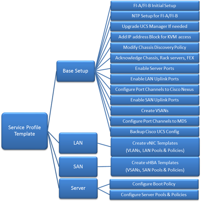
Cisco UCS Configuration – Base Setup
This section outlines the initial setup necessary to deploy a new Cisco UCS domain in a Cisco-Nimble environment using a pair of Cisco UCS Fabric interconnects (FI) with embedded Cisco UCS Manager for management.
Initial Setup of Cisco Fabric Interconnects
A pair of Cisco UCS 6248UP Fabric Interconnects is used in this design. Minimum configuration required to bring up the FIs and embedded Cisco UCS Manager (UCSM) are outlined below. All configurations after this will be done using Cisco UCS Manager.
Cisco UCS 6248UP FI – Primary (FI-A)
1. Connect to the console port of the primary Cisco UCS FI.
Enter the configuration method: console
Enter the setup mode; setup newly or restore from backup.(setup/restore)? Setup You have chosen to setup a new fabric interconnect? Continue? (y/n): y
Enforce strong passwords? (y/n) [y]: y
Enter the password for "admin": <Enter Password>
Enter the same password for "admin": <Enter Password>
Is this fabric interconnect part of a cluster (select 'no' for standalone)? (yes/no)[n]: y
Which switch fabric (A|B): A
Enter the system name: D01-FI-A
Physical switch Mgmt0 IPv4 address: 192.168.155.8
Physical switch Mgmt0 IPv4 netmask: 255.255.255.0
IPv4 address of the default gateway: 192.168.155.1
Cluster IPv4 address: 192.168.155.89
Configure DNS Server IPv4 address? (yes/no) [no]: y
DNS IPv4 address: 192.168.155.15
Configure the default domain name? y
Default domain name: smartstack.local
Join centralized management environment (UCS Central)? (yes/no) [n]: <Enter>
2. Review the settings printed to the console. If they are correct, answer yes to apply and save the configuration.
3. Wait for the login prompt to make sure that the configuration has been saved prior to proceeding.
Cisco UCS 6248UP FI – Secondary (FI-B)
1. Connect to the console port on the second FI on Cisco UCS 6248UP FI.
Enter the configuration method: console
Installer has detected the presence of a peer Fabric interconnect. This Fabric interconnect will be added to the cluster. Do you want to continue {y|n}? y
Enter the admin password for the peer fabric interconnect: <Enter Password>
Physical switch Mgmt0 IPv4 address: 192.168.155.9
Apply and save the configuration (select ‘no’ if you want to re-enter)?(yes/no: y
2. Verify the above configuration by using Secure Shell (SSH) to login to each FI and verify the cluster status. Status should be as follows if the cluster is up and running properly.
D01-FI-A# show cluster state
Cluster Id: 0x8cb67462eb0c11e2-0x9fff002a6a419c64
A: UP, PRIMARY
B: UP, SUBORDINATE
HA READY
D01-FI-A#
3. Now you’re ready to log into Cisco UCS Manager using either the individual or cluster IPs of the Cisco UCS Fabric Interconnects.
Log into Cisco UCS Manager
To log into the Cisco Unified Computing System (UCS) environment, complete the following steps:
1. Open a web browser and navigate to the Cisco UCS 6248 Fabric Interconnect cluster IP address configured in earlier step.
2. Click Launch Cisco UCS Manager link to download the Cisco UCS Manager software.
3. If prompted, accept security certificates as necessary.
4. When prompted, enter admin as the user name and enter the administrative password.
5. Click Login to log in to Cisco UCS Manager.
6. Select Yes or No to authorize Anonymous Reporting if desired and click OK.
Cisco UCS Manager – Configure NTP Server
To synchronize the Cisco UCS environment to the NTP server, complete the following steps:
1. Login to Cisco UCS manager using a web browser.
2. Click on the Admin icon in the side navigation pane.
3. Select All > Time Zone Management > Timezone.
4. Right-click and select Add NTP Server.
5. In the Add NTP Server pop-up window, specify NTP Server IP (for example, 192.168.155.254) and click OK twice to save edits.
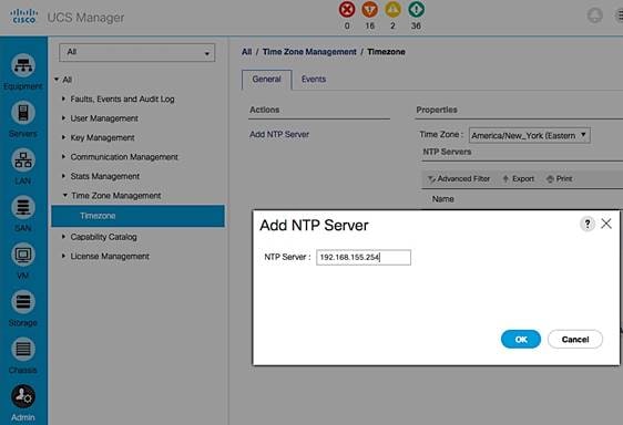
6. Specify the actual Time Zone in the Properties section of the Time Zone window.
Upgrading Cisco UCS Manager
This document assumes that the Cisco UCS Manager is running the version outlined in the Software Matrix. If an upgrade is required, follow the procedures outlined in the Cisco UCS Install and Upgrade Guides.
Assign Block of IP addresses for KVM Access
To create a block of IP addresses for in-band access to servers in the Cisco UCS environment, complete the following steps. The addresses are used for Keyboard, Video, and Mouse (KVM) access to individual servers managed by Cisco UCS Manager.
![]() This block of IP addresses should be in the same subnet as the management IP addresses for the Cisco UCS Manager.
This block of IP addresses should be in the same subnet as the management IP addresses for the Cisco UCS Manager.
1. Login to Cisco UCS Manager using a web browser.
2. Click on the LAN icon in the side navigation pane.
3. Select LAN > Pools > root > IP Pools.
4. Right-click and select Create IP Pool.
5. In the Create IP Pool dialogue box, specify a Name (for example, ext-mgmt) for the pool. Click Next.
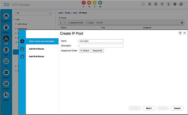
6. Click [+] Add to add a new IPv4 Block. Click Next.
7. Enter the starting IP address (From), the number of IP addresses in the block (Size), the Subnet Mask, Default Gateway and DNS information. Click OK.
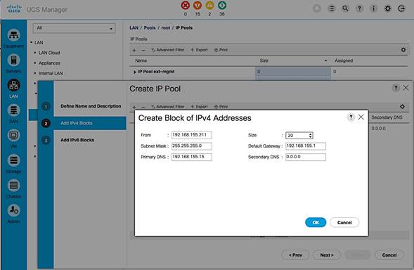
8. Click Finish to create an IPv4 block for KVM Access.
Edit Chassis Discovery Policy
Setting the discovery policy simplifies the addition of Cisco US Blade Server chassis and fabric extenders for Cisco UCS C-Series connectivity. To modify the chassis discovery policy, complete the following steps:
1. Login to Cisco UCS Manager using a web browser.
2. Click on the Equipment icon in the side navigation pane.
3. Select Equipment from the list on the left.
4. In the right pane, click Policies tab.
5. Under the Global Policies tab, set the Chassis/FEX Discovery Policy to match the number of uplink ports that are cabled between the chassis or fabric extenders (FEXes) and the fabric interconnects.
Set the Link Grouping Preference to Port Channel.
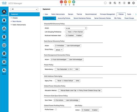
6. Click Save Changes and then OK to complete.
Acknowledge Cisco UCS Chassis, Cisco UCS C-series and FEX
To acknowledge all Cisco UCS chassis and C-Series Servers, complete the following steps:
1. Login to Cisco UCS Manager using a web browser.
2. Click on the Equipment icon in the side navigation pane.
3. Select Equipment > Chassis.
4. For each chassis in the deployment, right-click and select Acknowledge Chassis.
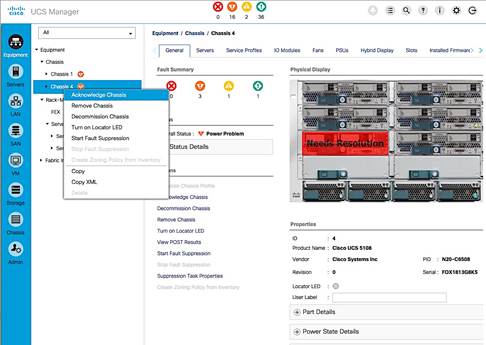
5. In the Acknowledge Chassis pop-up, click Yes and then click OK.
6. If C-Series servers are part of the deployment, go to Rack Mounts > Servers.
7. For each server listed, right-click and select Acknowledge Chassis. Using FEX for rack mount servers is a design option in the design. If FEX is used, acknowledge each FEX.
Enable Server Ports
To configure ports connected to Cisco UCS servers as Server ports, complete the following steps:
1. Login to Cisco UCS Manager using a web browser.
2. Click on the Equipment icon in the side navigation pane.
3. Select Equipment > Fabric Interconnects > Fabric Interconnect A (primary) > Fixed Module.
4. Expand Ethernet Ports.
5. Select the ports that are connected to Cisco UCS Blade server chassis, Cisco UCS C-series servers or any FEX used for C-series connectivity. Right-click and select Configure as Server Port.
6. Click Yes and then OK to confirm the changes.
7. Repeat above steps for Fabric Interconnect B (secondary) ports that connect to servers.
8. Verify that the ports connected to the servers in the setup are now configured as server ports. The view below is filtered to only show Server ports.
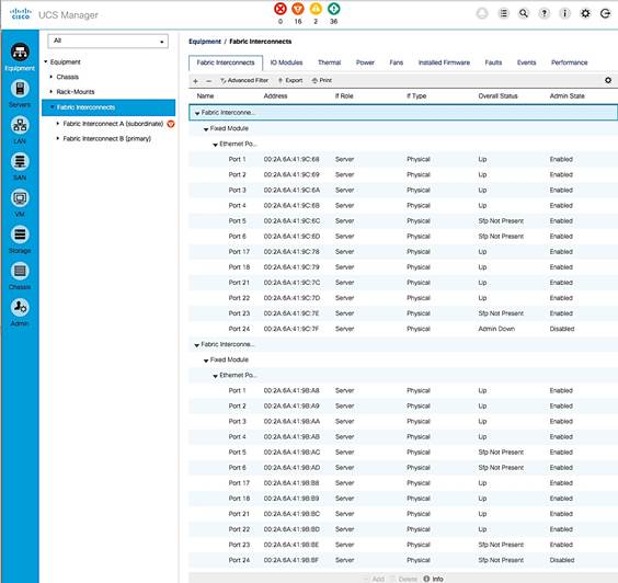
Enable Uplink Ports to Cisco Nexus 9000 Series Switches
To configure ports connected to Cisco Nexus switches as Network ports, complete the following steps:
1. Login to Cisco UCS Manager using a web browser.
2. Click on the Equipment icon in the side navigation pane.
3. Select Equipment > Fabric Interconnects > Fabric Interconnect A (primary) > Fixed Module.
4. Expand Ethernet Ports.
5. Select the first port (for example, Port 15) that connects to Cisco Nexus A switch, right-click and select Configure as Uplink Port, click Yes to confirm the uplink ports and click OK. Repeat for second port (for example, Port 16) that connects to Cisco Nexus B switch.
6. Repeat above steps for Fabric Interconnect B uplink ports that connect to Cisco Nexus switches.
7. Verify that the ports connected to the servers are now configured as server ports. The view below is filtered to only show Network ports.
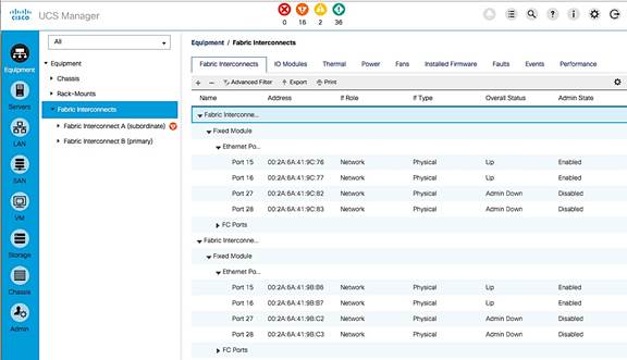
Configure Port Channels on Uplink Ports to Cisco Nexus Switches
In this procedure, two port channels are created, one from Fabric A to both Cisco Nexus switches and one from Fabric B to both Cisco Nexus switches. To configure port channels on Uplink/Network ports connected to Cisco Nexus switches, complete the following steps:
1. Login to Cisco UCS Manager using a web browser.
2. Click on the LAN icon in the side navigation pane.
3. Select LAN > LAN Cloud > Fabric A > Port Channels.
4. Right-click and select Create Port Channel.
5. In the Create Port Channel window, specify a Name and unique ID. Click Next.
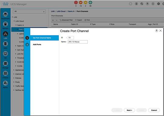
6. In the Add Ports screen, select the ports to put in the channel (for example, Eth1/15 and Eth1/16). Click on the >> box to add the ports the port-channel. Click Finish to create the port channel.
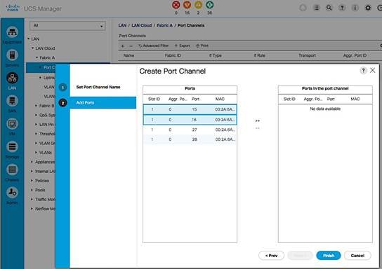
7. Verify the resulting configuration is as shown below.
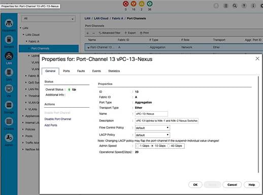
8. Repeat above steps for Fabric B and verify the configuration is as shown below.
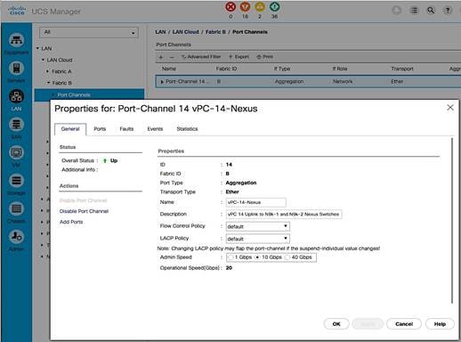
Enable Fibre Channels Ports to Cisco MDS 9100 Series Switches
Cable the following FC connections as specified in the figure below. Complete the steps below to configure the Fabric Interconnects ports that connect to upstream Cisco MDS switches.
Figure 13 FC Connections
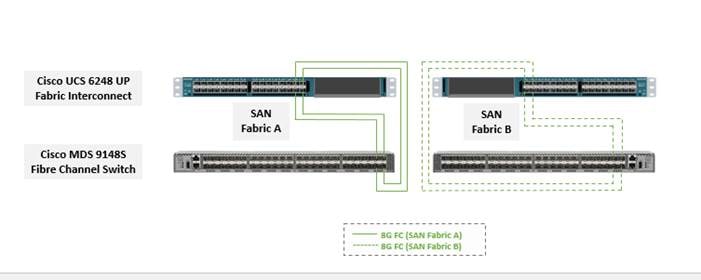
1. Login to Cisco UCS Manager using a web browser.
2. Click on the Equipment icon in the side navigation pane.
3. Select Equipment > Fabric Interconnects > Fabric Interconnect A (primary) > Fixed Module.
4. Expand FC Ports.
5. Select the first port (for example, Port 29) that connects to the Cisco MDS-A switch for SAN Fabric A, right-click and Configure as Uplink Port, click Yes to confirm. Repeat for the following 3 ports (for example, Ports 30 – 32) that connect to the same Cisco MDS switch.
6. Repeat above steps on the Fabric Interconnect B to configure the ports connected to the Cisco MDS-B switch in SAN Fabric B.
Create VSAN for Fibre Channel Interfaces
Create VSAN for SAN Fabric A
1. Login to Cisco UCS Manager using a web browser. Click on the SAN icon in the side navigation pane.
2. Select SAN > SAN Cloud > Fabric A > VSANs.
3. Right click and select Create VSAN. Specify a VSAN name for Fabric A (for example, VSAN-A). Select Fabric A radio button. Specify the VSAN ID (for example, 4091) and FCoE VLAN ID (for example, 4091). The configuration should match the upstream Cisco MDS-A switch.
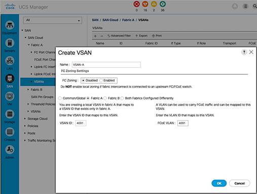
Create VSAN for SAN Fabric B
1. Login to Cisco UCS Manager using a web browser. Click on the SAN icon in the side navigation pane.
2. Select SAN > SAN Cloud > Fabric B > VSANs.
3. Right-click and select Create VSAN. Specify a VSAN name for Fabric B (for example, VSAN-B). Select Fabric B radio button. Specify the VSAN ID (for example, 4092) and FCoE VLAN ID (for example, 4092). The configuration should match the upstream Cisco MDS-B switch.
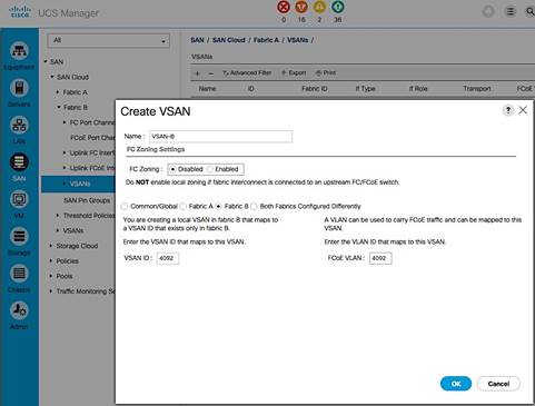
Configure Port Channels on Fibre Channel Uplinks to Cisco MDS Switches
Configure Port Channels from Fabric A to Cisco MDS-A
1. Login to Cisco UCS Manager using a web browser. Click on the SAN icon in the side navigation pane.
2. Select SAN > SAN Cloud > Fabric A > FC Port Channels.
3. Right click and select Create Port Channel. The configuration should match the upstream Cisco MDS-A switch. In the Create FC Port Channel window, specify the port channel number (for example, 41) and assign it a name (for example, VSAN-A-PC). Click Next.
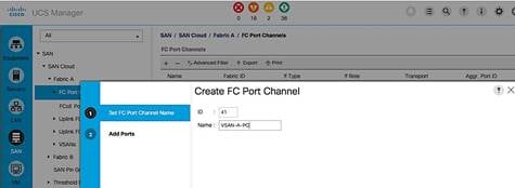
4. In the Add Ports screen, select the previously configured four ports. And then, click on the ![]() button. Click Finish to create the port channel to Cisco MDS-A switch.
button. Click Finish to create the port channel to Cisco MDS-A switch.
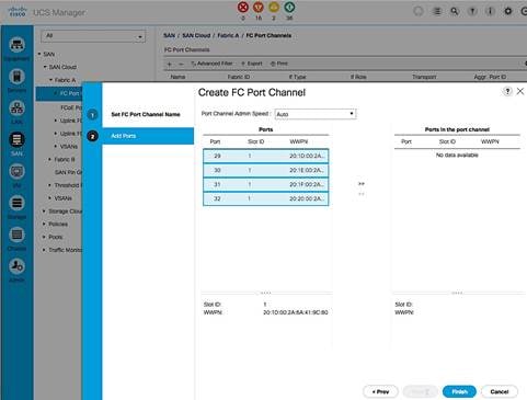
5. Navigate to the newly created port channel under Fabric A and change the VSAN to be the one created earlier for Fabric A (for example, 4091).
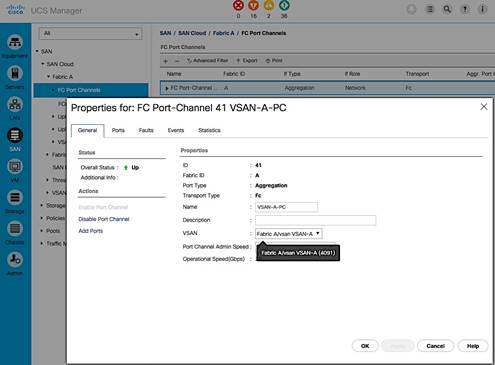
Configure Port Channels from Fabric B to Cisco MDS-B
1. Login to Cisco UCS Manager using a web browser. Click on the SAN icon in the side navigation pane.
2. Select SAN > SAN Cloud > Fabric B > FC Port Channels.
3. Right click and select Create Port Channel. Configuration should match the upstream Cisco MDS-A switch. Select a port channel number (for example, 42) and assign it a name (for example, VSAN-B-PC). Click Next.
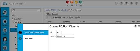
4. In the Add Ports window, highlight the 4 previously configured ports and click on the ![]() button to add the ports to the port channel. Click Finish to create the port channel to Cisco MDS-B switch.
button to add the ports to the port channel. Click Finish to create the port channel to Cisco MDS-B switch.
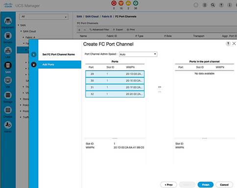
5. Navigate to the newly created port channel under Fabric B and change to Fabric B VSAN.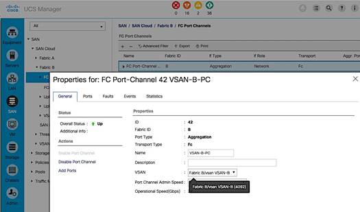
Cisco UCS Configuration Backup
The Cisco UCS Configuration should be backed up. For details on how to do the backup, see: http://www.cisco.com/c/en/us/td/docs/unified_computing/ucs/ucs-manager/GUI-User-Guides/Admin-Management/3-1/b_Cisco_UCS_Admin_Mgmt_Guide_3_1/b_Cisco_UCS_Admin_Mgmt_Guide_3_1_chapter_01001.html
Cisco UCS Configuration – LAN
LAN Configuration Workflow
The workflow below shows the LAN configuration on Cisco UCS resulting in the creation of vNIC templates. The vNIC Templates encapsulate the LAN configuration of Cisco UCS. The vNIC templates are created through Fabric A and Fabric B for redundancy and load balancing. The configuration steps to implement the workflow are outlined in the following subsections.
Figure 14 LAN Configuration Workflow

Create VLANs
This section shows the configuration steps for creating vlans for LAN connectivity to the Nexus switching fabric. The vlans configured include native vlan, in-band management vlan, vMotion vlan and Application Data vlans. Follow the same steps to create additional vlans as needed.
Change the Default Native VLAN on Uplink ports to Cisco Nexus 9000 Series Switches
Per security best practices, the native VLAN should be changed from its default value i.e. from VLAN 1 to a different value. In this setup, VLAN 2 was used. Complete the following steps to configure the new native vlan.
1. From Cisco UCS Manager, click on the LAN icon in the navigation pane.
2. Select LAN > LAN Cloud > VLANs.
3. Right-click and select Create VLANs. Specify a name (for example, NATIVE-VLAN) and VLAN ID (for example, 2). Leave everything else as default.
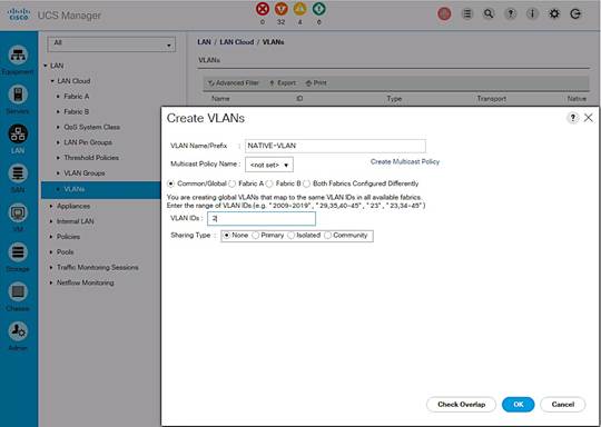
4. Since the newly created VLAN is a native VLAN, right-click on the newly created VLAN from the list of VLANs and select Set as Native VLAN from the menu. This VLAN should match the native VLAN used on upstream switch.
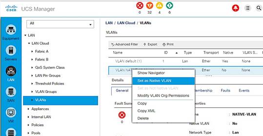
Create Management VLAN on Uplink ports to Cisco Nexus 9000 Series Switches
The management VLAN is necessary for in-band management access to Cisco UCS hosts and virtual machines running on them. Complete the following steps to configure management vlan.
1. From Cisco UCS Manager, click on the LAN icon in the navigation pane.
2. Select LAN > LAN Cloud > VLANs. Right-click and select Create VLANs.
3. Specify a name (IB-MGMT-VLAN) and VLAN ID (12). Leave everything else as default.
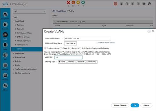
Create vMotion VLAN on Uplink ports to Cisco Nexus 9000 Series Switches
The vMotion VLAN is necessary for supporting vMotion between hosts in the Cisco UCS domain and other domains in the data center. vMotion will use a dedicated vNIC on each host per VMware vSphere best practices.
1. From Cisco UCS Manager, click on the LAN icon in the navigation pane.
2. Select LAN > LAN Cloud > VLANs.
3. Right-click and select Create VLANs. Specify the vlan name and ID.
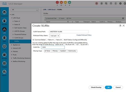
Create Application Data VLANs on Uplink ports to Cisco Nexus 9000 Series Switches
To validate this architecture, two applications VLANs (APP1-VLAN, APP2-VLAN) were created using the above steps and trunked through Cisco Nexus 9000 series switches to other parts of the network. Repeat as needed for any additional VLANs created on the upstream Nexus switches.
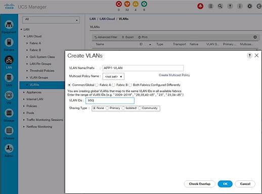
VLAN Summary View
A summary of the VLANs created in the previous steps are shown below.
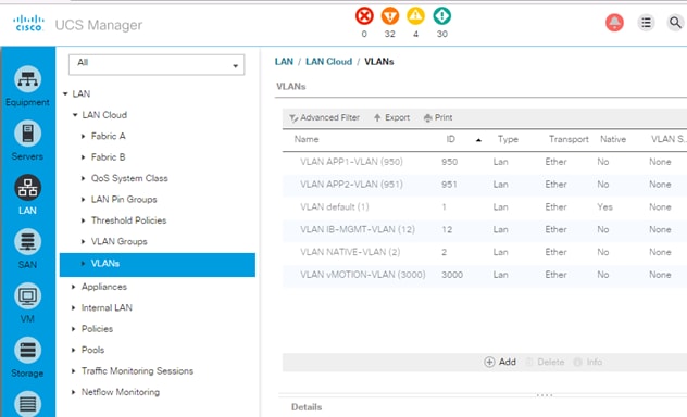
Create LAN Pools
Create MAC Address Pools
MAC Address Pool can be defined to make troubleshooting easy if needed. In this setup, the 4th and 5th octet of the mac address is modified to reflect the fabric the host uses - AA:AA for Fabric A and BB:BB for Fabric B.
Create MAC pool for Fabric Interconnect A
The MAC addresses in this pool will be used for traffic through Fabric Interconnect A.
1. From Cisco UCS Manager, click on the LAN icon in the navigation pane.
2. Select LAN > Pools > root > MAC Pools.
3. Right-click and select Create Mac Pool.
4. Specify a name (for example, MAC-POOL-FI-A) that identifies this pool is specific to Fabric Interconnect A. Select the Assignment Order as Sequential. Click Next.
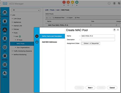
5. Click [+] Add to add a new MAC pool.
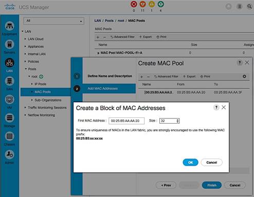
6. For ease-of-troubleshooting, change the 4th and 5th octet to AA:AA traffic using Fabric Interconnect A. Generally speaking, the first three octets of a mac-address should not be changed. Select a size (for example, 32).
7. Select OK and then click Finish to add the MAC pool.
Create MAC pool for Fabric Interconnect B
The MAC addresses in the pool will be used for traffic using Fabric Interconnect B.
1. From Cisco UCS Manager, click on the LAN icon in the navigation pane.
2. Select LAN > Pools > root > Mac Pools.
3. Right-click and select Create Mac Pool.
4. Specify a name (for example, MAC-POOL-FI-B) that identifies this pool is specific to Fabric Interconnect B. Select the Assignment Order as Sequential and click Next.
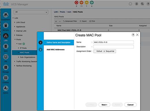
5. Click [+] Add to add a new MAC pool.
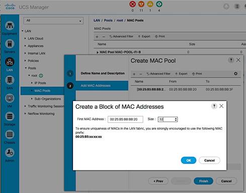
6. For ease-of-troubleshooting, change the 4th and 5th octet to BB:BB traffic using Fabric Interconnect A. Generally speaking, the first three octets of a mac-address should not be changed. Select a size (for example, 32).
7. Select OK and then click Finish to add the MAC pool.
MAC Pool Summary View
The resulting configuration is shown below.
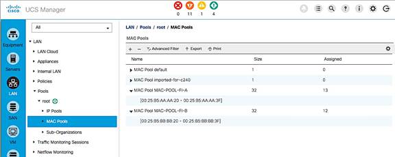
Create LAN Policies
Enable Jumbo Frame Support in UCS Fabric
To enable jumbo frame through the UCS fabric, change the MTU for the specific QoS traffic class to 9216B. In this setup, all traffic except for fibre channel traffic uses the Best Effort class. The MTU for this class was changed from the default of ‘normal’ or 1500B to the maximum supported value of 9216B for traffic that can benefit from jumbo frames such as vMotion. The MTU for UCS fabric in QoS system class should be equal to or higher than the MTU specified in the vNIC template.
1. From Cisco UCS Manager, click on the LAN icon in the navigation pane.
2. Select LAN > LAN Cloud > QOS System Class.
3. Select the Enabled checkbox for Best Effort class.
4. For the same row, change the MTU from normal to 9216B and default for everything else.
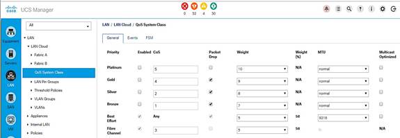
5. Click Save Changes and then OK to accept.
Configure Network Control Policy for Uplinks
For Uplink ports connected to Cisco Nexus switches, enable Cisco Discovery Protocol (CDP). CDP can be useful for troubleshooting by discovering and learning about devices connected to ports where CDP is enabled.
1. From Cisco UCS Manager, click on the LAN icon in the navigation pane.
2. Select LAN > Policies > LAN Cloud > root > Network Control Policies.
3. Right-click and select Create Network Control Policy.
4. Specify a Name for the network control policy (Enable_CDP). Select Enabled for CDP.
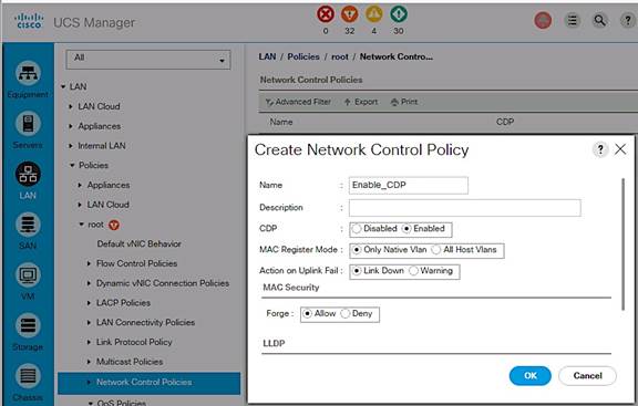
5. Click OK to create network control policy.
Create vNIC Templates
vNIC templates encapsulate the LAN configuration of Cisco UCS. vNIC templates for Management, vMotion and Application Data are created through Fabric A and Fabric B for a total of 6 vNIC templates. A host will have connectivity to both Fabric A and Fabric B.
Table 5 vNIC Template Configuration Summary
Complete the following steps to create the vNIC templates.
| Template Name |
Fabric |
VLANs |
MAC Pool |
Used For |
| vNIC-T-MGMT-A |
A |
IB-MGMT-VLAN, |
MAC-POOL-FI-A |
All ESXi Management |
| vNIC-T-MGMT-B |
B |
IB-MGMT-VLAN, |
MAC-POOL-FI-B |
All ESXi Management |
| vNIC-T-vMOTION-A |
A |
vMOTION-VLAN |
MAC-POOL-FI-A |
All vMotion traffic |
| vNIC-T-vMOTION-B |
B |
vMOTION-VLAN |
MAC-POOL-FI-B |
All vMotion traffic |
| vNIC-T-A |
A |
APP1-VLAN, |
MAC-POOL-FI-A |
All Application |
| vNIC-T-B |
B |
APP1-VLAN, |
MAC-POOL-FI-B |
All Application |
Create vNIC Template for Management through Fabric A
1. From Cisco UCS Manager, click on the LAN icon in the navigation pane.
2. Select LAN > Policies > root > vNIC Templates.
3. Right-click and select Create vNIC Template.
4. Specify a template Name (for example, vNIC-T-MGMT-A) for the policy.
5. Keep Fabric A selected and leave Enable Failover checkbox unchecked.
6. Select Redundancy Type as Primary Template.
7. Leave the Peer Redundancy Template as <not set>.
8. Under Target, make sure that the VM checkbox is NOT selected.
9. Specify the Template Type as Updating Template.
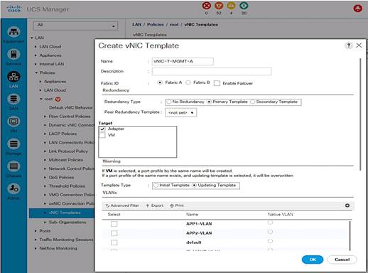
10. Under VLANs, select the checkbox for management VLAN (IB-MGMT-VLAN) and the new native vlan (NATIVE-VLAN). Check the Native VLAN radio button for this vlan.
11. Set MTU to the maximum configurable value of 9000 (equal/less than QoS System Class MTU) to avoid a vNIC template update and host reboot to support jumbo frame in the future.
12. For MAC Pool, select the previously configured LAN pool (MAC-POOL-FI-A).
13. For Network Control Policy, select the previously configured LAN policy (Enable_CDP).
14. Choose the default values in the Connection Policies section.
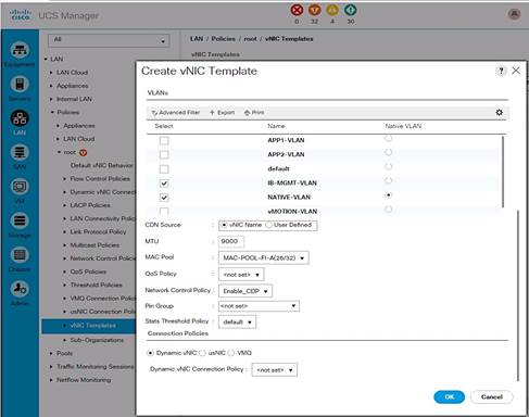
15. Click OK twice to create the vNIC template.
Create vNIC Template for Management through Fabric B
1. From Cisco UCS Manager, click on the LAN icon in the navigation pane.
2. Select LAN > Policies > root > vNIC Templates.
3. Right-click and select Create vNIC Template.
4. Specify a template Name (for example, vNIC-T-MGMT-B) for the policy.
5. Select Fabric B and leave Enable Failover checkbox unchecked.
6. Select Redundancy Type as Secondary Template.
7. Set Peer Redundancy Template to Fabric A (vNIC-T-MGMT-A) from the drop down list.
8. Under Target, make sure that the VM checkbox is NOT selected.
9. Specify the Template Type as Updating Template.
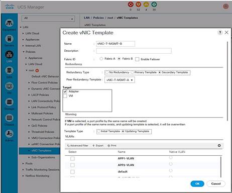
10. Under VLANs, select the checkbox for management VLAN (IB-MGMT-VLAN) and the new native vlan (NATIVE-VLAN). Check the Native VLAN radio button for this vlan.
11. Set MTU to the maximum configurable value of 9000 (equal/less than QoS System Class MTU) to avoid a vNIC template update and host reboot to support jumbo frame in the future.
12. For MAC Pool, select the previously configured LAN pool (MAC-POOL-FI-B).
13. For Network Control Policy, select the previously configured LAN policy (Enable_CDP).
14. Choose the default values in the Connection Policies section.
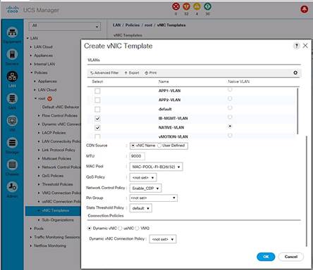
15. Click OK twice to create the vNIC template.
Create vNIC Template for vMotion through Fabric A
1. From Cisco UCS Manager, click on the LAN icon in the navigation pane.
2. Select LAN > Policies > root > vNIC Templates.
3. Right-click and select Create vNIC Template.
4. Specify a template Name (for example, vNIC-T-vMOTION-A) for the policy.
5. Keep Fabric A selected and leave Enable Failover checkbox unchecked.
6. Select Redundancy Type as Primary Template.
7. Leave the Peer Redundancy Template as <not set>.
8. Under Target, make sure that the VM checkbox is NOT selected.
9. Specify the Template Type as an Updating Template.
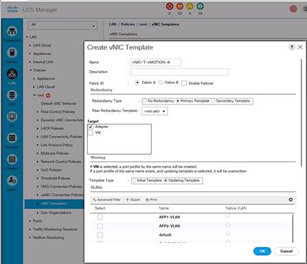
10. Under VLANs, select the checkbox for vMotion VLAN (vMOTION-VLAN).
11. To maximize vMotion performance, set MTU to 9000 (equal/less than QoS System Class).
12. For MAC Pool, select the previously configured LAN pool (MAC-POOL-FI-A).
13. For Network Control Policy, select the previously configured LAN policy (Enable_CDP).
14. Choose the default values in the Connection Policies section.
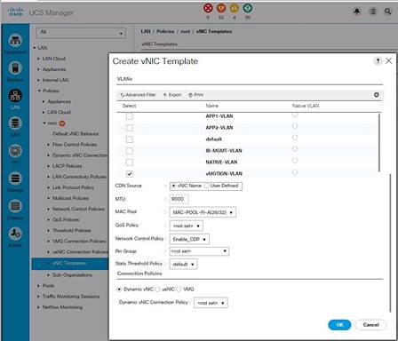
15. Click OK twice to create the vNIC template.
Create vNIC Template for vMotion through Fabric B
1. From Cisco UCS Manager, click on the LAN icon in the navigation pane.
2. Select LAN > Policies > root > vNIC Templates.
3. Right-click and select Create vNIC Template.
4. Specify a template Name (for example, vNIC-T-vMOTION-B) for the policy.
5. Select Fabric B and leave Enable Failover checkbox unchecked.
6. Select Redundancy Type as Secondary Template.
7. Set Peer Redundancy Template to Fabric A (vNIC-T-vMOTION-A) from the drop down list.
8. Under Target, make sure that the VM checkbox is NOT selected.
9. Specify the Template Type as Updating Template.
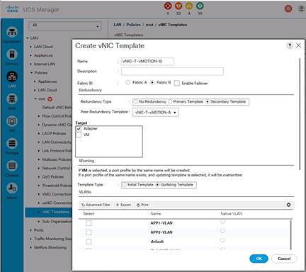
10. Under VLANs, select the checkbox for vMotion VLAN (vMOTION-VLAN).
11. To maximize vMotion performance, set MTU to 9000 (equal/less than QoS System Class).
12. For MAC Pool, select the previously configured LAN pool (MAC-POOL-FI-B).
13. For Network Control Policy, select the previously configured LAN policy (Enable_CDP).
14. Choose the default values in the Connection Policies section.
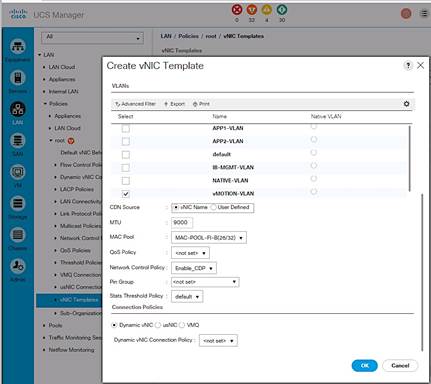
Click OK twice to create the vNIC template.
Create vNIC Template for Application Traffic through Fabric A
1. From Cisco UCS Manager, click on the LAN icon in the navigation pane.
2. Select LAN > Policies > root > vNIC Templates.
3. Right-click and select Create vNIC Template.
4. Specify a template Name (for example, vNIC-T-A) for the policy.
5. Keep Fabric A selected and leave Enable Failover checkbox unchecked.
6. Select Redundancy Type as Primary Template.
7. Leave the Peer Redundancy Template as <not set>.
8. Under Target, make sure that the VM checkbox is NOT selected.
9. Specify the Template Type as Updating Template.
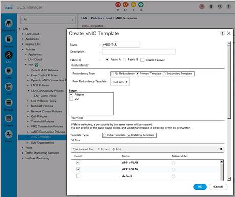
10. Under VLANs, select the checkbox for management VLAN (APP1-VLAN, APP2-VLAN).
11. Set MTU to the maximum configurable value of 9000 (equal/less than QoS System Class MTU) to avoid a vNIC template update and host reboot to support jumbo frame in the future.
12. For MAC Pool, select the previously configured LAN pool (MAC-POOL-FI-A).
13. For Network Control Policy, select the previously configured LAN policy (Enable_CDP).
14. Choose the default values in the Connection Policies section.
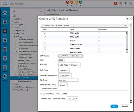
15. Click OK twice to create the vNIC template.
Create vNIC Template for Application Traffic through Fabric B
1. From Cisco UCS Manager, click on the LAN icon in the navigation pane.
2. Select LAN > Policies > root > vNIC Templates.
3. Right-click and select Create vNIC Template.
4. Specify a template Name (for example, vNIC-T-B) for the policy.
5. Select Fabric B and leave Enable Failover checkbox unchecked.
6. Select Redundancy Type as Secondary Template.
7. Set Peer Redundancy Template to Fabric A (vNIC-T-A) from the drop down list.
8. Under Target, make sure that the VM checkbox is NOT selected.
9. Specify the Template Type as Updating Template.
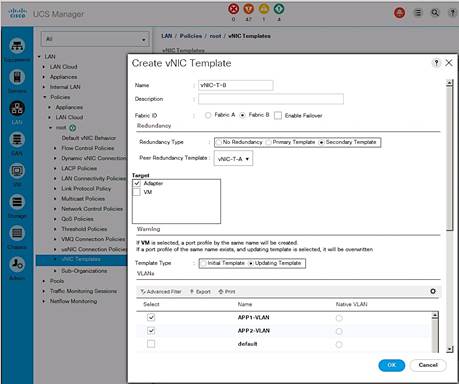
10. Under VLANs, select the checkbox for management VLAN (APP1-VLAN, APP2-VLAN).
11. Set MTU to the maximum configurable value of 9000 (equal/less than QoS System Class MTU) to avoid a vNIC template update and host reboot to support jumbo frame in the future.
12. For MAC Pool, select the previously configured LAN pool (MAC-POOL-FI-B).
13. For Network Control Policy, select the previously configured LAN policy (Enable_CDP).
14. Choose the default values in the Connection Policies section.
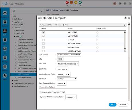
15. Click OK twice to create the vNIC template.
Create LAN Connectivity Policies
The LAN connectivity policy defines the configuration of network resources used in a service profile and is typically defined by the LAN Administrator. The network resources include vNICs, iSCSI vNICs (if used), VLANs, MAC Pools, Adapter policies, pinning etc. Additional vNICs can be created as needed.
Table 6 LAN Connectivity Policy
| vNIC Name |
vNIC Template Name |
Adapter Policy |
Used For |
| 00-MGMT-A |
vNIC-T-MGMT-A |
VMware |
All ESXi Management |
| 01-MGMT-B |
vNIC-T-MGMT-B |
VMware |
All ESXi Management |
| 02-vMOTION-A |
vNIC-T-vMOTION-A |
VMware |
All vMotion traffic |
| 03-vMOTION-B |
vNIC-T-vMOTION-B |
VMware |
All vMotion traffic |
| 04-vNIC-A |
vNIC-T-A |
VMware |
All Application Vlan traffic |
| 05-vNIC-B |
vNIC-T-B |
VMware |
All Application Vlan traffic |
Complete the following steps to create the LAN Connectivity Policy:
1. From Cisco UCS Manager, click on the LAN icon in the navigation pane.
2. Select LAN > Policies > root > LAN Connectivity Policies.
3. Right-click LAN Connectivity Policies and choose Create LAN Connectivity Policy.
4. Specify a name for the LAN Connectivity Policy (for example, LAN-Conn-Policy).
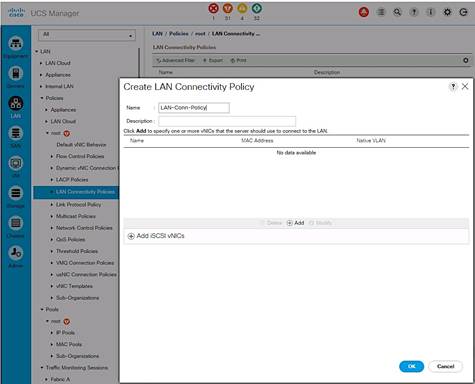
Create vNICs and Add to LAN Connectivity Policy
1. In the Create LAN Connectivity Policy window, click [+] Add to add a vNIC.
2. In the Create vNIC dialog box, specify the first vNIC name from the table above.
3. Select the Use vNIC Template checkbox.
4. For the vNIC Template, find the corresponding vNIC template from the table above and select it from the drop-down list.
5. For the Adapter Policy field, select VMWare.
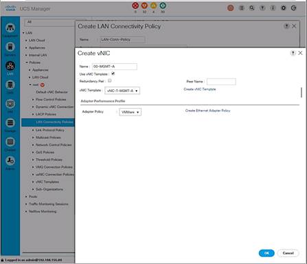
6. Click OK to add this vNIC to the policy.
7. Repeat these steps to add the remaining vNICs from the table above to complete the LAN Connectivity policy as shown below for this deployment.
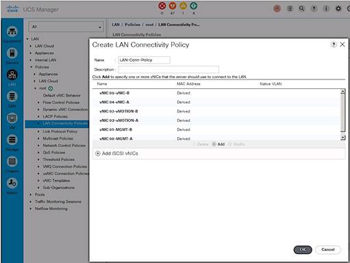
Cisco UCS Configuration – Server
Server Configuration Workflow
The workflow below shows the high level server configuration workflow. The subsections that follow will cover the configuration of the individual steps in the workflow.
Figure 15 Server Configuration Workflow
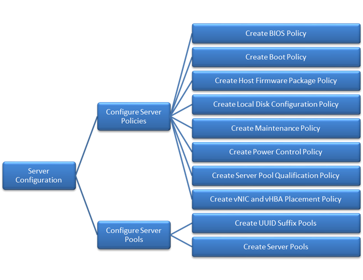
Configure Server Policies
The procedures for creating the different server policies deployed in this solution are covered in this section.
Create BIOS Policy
The BIOS settings used in this setup is based on the recommendations published on cisco.com for Cisco UCS M4 servers. The recommendations can be found in this whitepaper: Performance Tuning Guide for Cisco UCS M4 Servers.
To create a server BIOS policy for Cisco UCS hosts, complete the following steps:
1. In Cisco UCS Manager, click Servers tab in the navigation pane.
2. Select Policies > root > BIOS Policies.
3. Right-click and select Create BIOS Policy.
4. In the Main window, enter BIOS Policy Name (for example, VM-Host-Infra). Change the Quiet Boot setting to Disabled and Consistent Device Naming to Enabled. Click Next.
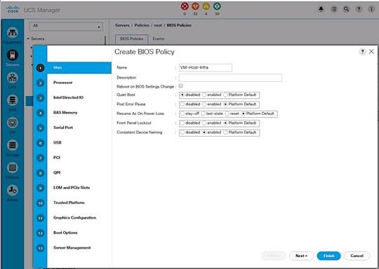
5. In the Processor screen, change the following. Scroll down to find all the settings. Click Next.
a. Turbo Boost to Enabled
b. Enhanced Intel Speedstep to Enabled
c. Hyper Threading to Enabled
d. Execution Disabled Bit to Enabled
e. Virtualization Technology (VT) to Enabled
f. Direct Cache Access to Enabled
g. Processor C-states to disabled
h. CPU Performance to Enterprise
i. Power Technology to Performance
j. Energy Performance to Performance
k. Frequency-floor override to Enabled
l. DRAM clock throttling to Performance
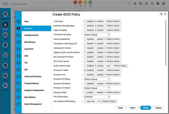
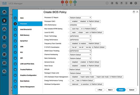
6. In the Intel Directed IO screen, change the VT for Direct IO to Enabled. Click Next.
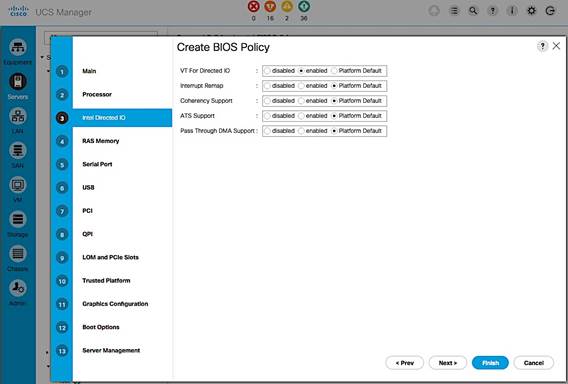
7. In the RAS Memory screen, change the following.
a. Memory RAS Config to maximum-performance
b. LV DDR Mode to performance-mode
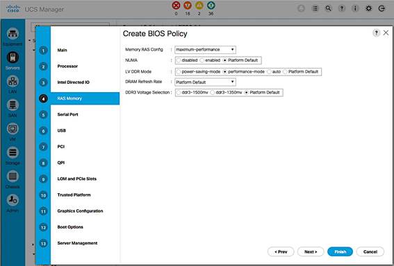
8. In the Intel QuickPath Interconnect (QPI) screen, QPI snoop mode should be set to Platform Default.
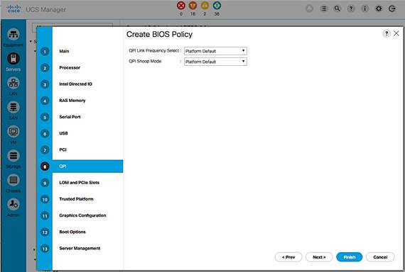
9. Click Finish and OK to create the BIOS policy.
Create Boot Policy
The procedure outlined in this section will create two boot policies (BOOT-FC-FIA, BOOT-FC-FIB) using one of the SAN fabrics as the primary path for booting. In the event of a failure, each boot policy is also configured with a secondary boot path that uses the other SAN fabric. Each boot policy is part of a larger Service Profile Template that generates the service profiles that hosts associate with. Service profiles can be evenly distributed across the deployment such that half of the hosts use the first boot policy and the other half uses the second boot policy. During a multi-host boot up event, this ensures that both SAN fabrics are utilized.
SAN Boot Topology
This CVD uses two arrays: AF7000 All Flash Array and CS5000 Adaptive Flash Array. The boot policy outlined below uses the AF7000 array to boot the hosts but the same steps can be used for the CS5000 adaptive flash array. This is possible because all Nimble Storage arrays are built upon a universal hardware architecture and run the same Nimble OS distribution (which constitutes the core of the Unified Flash Fabric). In this setup, both arrays are also connected to the same pair of Cisco MDS switches.
The following configuration assumes that each storage array controller contains two 16Gb FC interface cards, each with 2 ports that connect to the SAN fabrics. The two ports from each controller (FC1.1, FC2.1) that are used for booting are highlighted in the figure below.
Figure 16 SAN Boot Connectivity
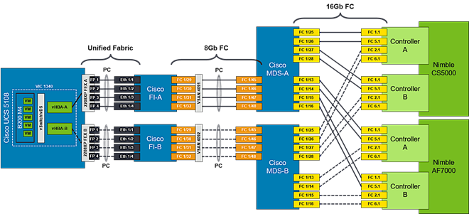
Each boot policy will use both SAN Fabrics with the primary and secondary SAN boot targets as shown below.
Boot Policy: BOOT-FC-FIA
· Primary Boot Paths:
- HBA-A à FI-A à SAN Fabric A (Cisco MDS-A) à Nimble Array (CNTL-A)
- HBA-A à FI-A à SAN Fabric A (Cisco MDS-A) à Nimble Array (CNTL-B)
· Secondary Boot Paths:
- HBA-B à FI-B à SAN Fabric B (Cisco MDS-B) à Nimble Array (CNTL-A)
- HBA-B à FI-B à SAN Fabric B (Cisco MDS-B) à Nimble Array (CNTL-B)
Boot Policy: BOOT-FC-FIB
· Primary Boot Paths:
- HBA-B à FI-B à SAN Fabric B (Cisco MDS-B) à Nimble Array (CNTL-A)
- HBA-B à FI-B à SAN Fabric B (Cisco MDS-B) à Nimble Array (CNTL-B)
· Secondary Boot Paths:
- HBA-A à FI-A à SAN Fabric A (Cisco MDS-A) à Nimble Array (CNTL-A)
- HBA-A à FI-A à SAN Fabric A (Cisco MDS-A) à Nimble Array (CNTL-B)
Collect WWPN info from Nimble Unified Flash Fabric
Boot policies require the SAN Target information (WWPN) for FC boot. Use the following procedure to collect the information from the Nimble Storage array.
1. Login to web management interface of Nimble array.
2. Navigate to Administration > Network Configuration.
3. Click Active Settings link and then select the Interfaces tab.
4. Click Fibre Channel link to get a summary view of the WWPNs of all interfaces on the array. The WWPN of the Nimble array used in validation is used in the example below.
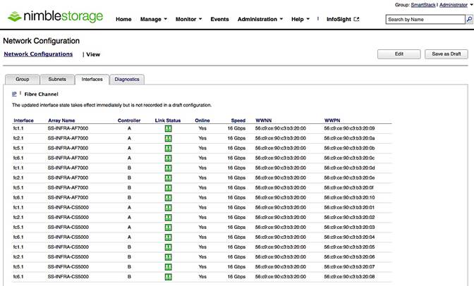
![]() Port WWPN information can alternately be collected via the array CLI using the “fc --list” command.
Port WWPN information can alternately be collected via the array CLI using the “fc --list” command.
SAN Boot Policy Configuration Summary
The information from the physical setup, required to configure the boot policies is shown in the table below.
Table 7 SAN Boot Policy Configuration Summary
| Boot Policy Name |
Boot Path |
SAN |
Nimble |
Nimble |
SAN Target |
| BOOT-FC-FIA |
Primary (vHBA-A) |
Primary |
A |
FC 1.1 |
56:c9:ce:90:c3:b3:20:09 |
| Secondary |
B |
FC 1.1 |
56:c9:ce:90:c3:b3:20:0D |
||
| Secondary (vHBA-B) |
Primary |
A |
FC 2.1 |
56:c9:ce:90:c3:b3:20:0A |
|
| Secondary |
B |
FC 2.1 |
56:c9:ce:90:c3:b3:20:0E |
||
| BOOT-FC-FIB |
Primary (vHBA-B) |
Primary |
A |
FC 2.1 |
56:c9:ce:90:c3:b3:20:0A |
| Secondary |
B |
FC 2.1 |
56:c9:ce:90:c3:b3:20:0E |
||
| Secondary (vHBA-A) |
Primary |
A |
FC 1.1 |
56:c9:ce:90:c3:b3:20:09 |
|
| Secondary |
B |
FC 1.1 |
56:c9:ce:90:c3:b3:20:0D |
Create Boot Policy using Fabric A as Primary Path
The first boot policy (BOOT-FC-FIA) will use Fabric A as the primary boot path. The following order of priority is used for booting.
· CD/DVD
· SAN Boot
- Primary Path: HBA-A à FI-A à SAN Fabric A (Cisco MDS-A) à Nimble (A/B)
- Secondary Path: HBA-B à FI-B à SAN Fabric B (Cisco MDS-B) à Nimble (A/B)
To create the above boot policy, follow the procedures outlined below.
1. From Cisco UCS Manager, click on the Servers icon in the navigation pane.
2. Select Policies > root > Boot Policies.
3. Right-click and select Create Boot Policy.
4. In the Create Boot Policy window, enter the policy name (BOOT-FC-FIA).
5. Keep the Reboot on the Boot Order Change check box unchecked.
6. Expand the Local Devices section of the window and select Add CD/DVD. The Local CD/DVD and Remote CD/DVD will be greyed out at this point.
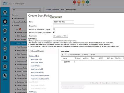
Create Primary Boot Path through Fabric A
1. Collapse the Local Devices section and expand the vHBAs section of the window. Click on Add SAN Boot.
2. In the Add SAN Boot dialog box, specify the vHBA (vHBA-A) for SAN Fabric A. For Type, select the Primary radio button. Click OK to complete.
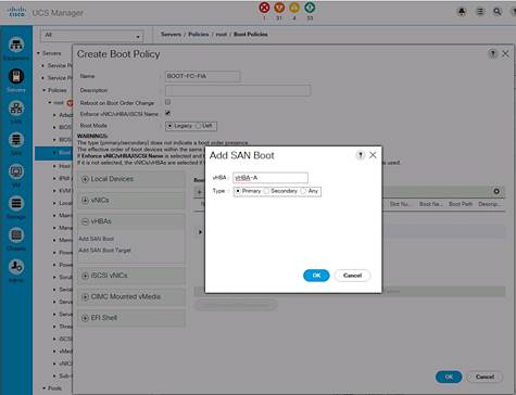
![]() The Add SAN Boot Target under vHBAs will be greyed until this step is complete.
The Add SAN Boot Target under vHBAs will be greyed until this step is complete.
3. In the vHBAs section of the window, click on Add SAN Boot Target.
4. In the Add SAN Boot Target dialog box, specify the Boot Target LUN as ‘0’ for this setup. Specify the ‘primary’ SAN Boot Target WWPN which is the primary controller port reachable through the primary boot path for this policy. From the table above, WWPN for the Nimble Controller A port (FC1.1) is: 56:c9:ce:90:c3:b3:20:09. Select the Type as ‘Primary’. Click OK to complete.

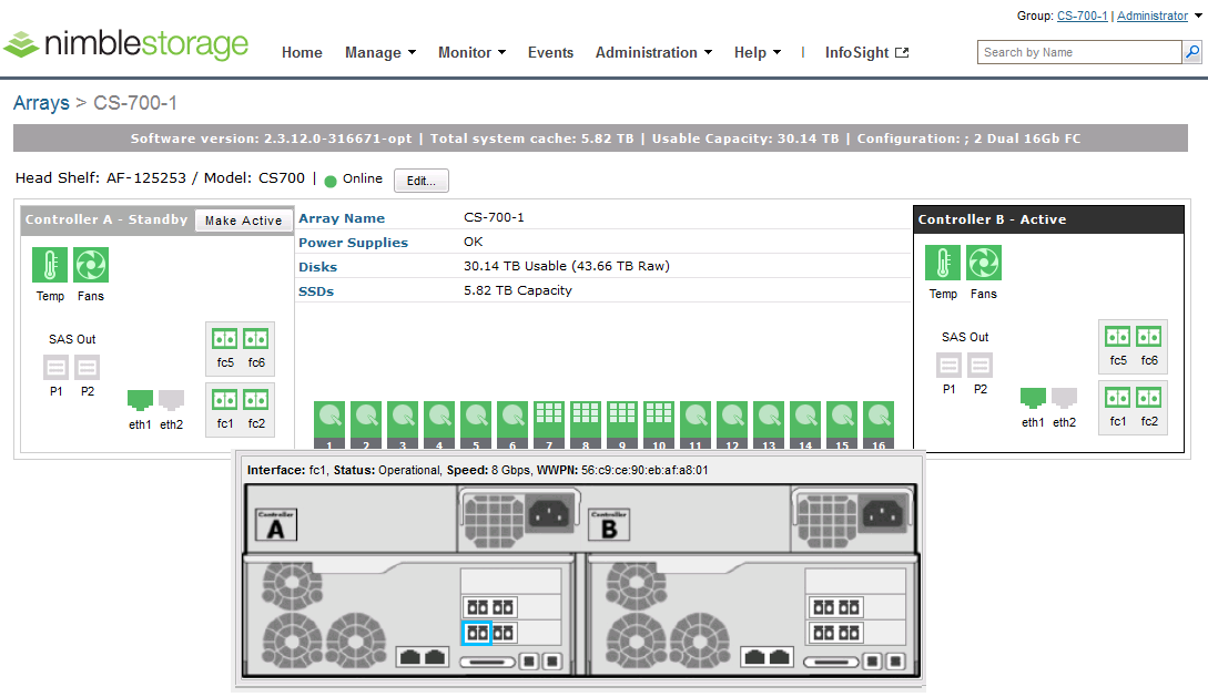
5. In the vHBAs section of the window, click on Add SAN Boot Target a second time to specify the backup SAN target for the primary boot path.
6. In the Add SAN Boot Target dialog box, specify the Boot Target LUN as ‘0’ for this setup. Specify the ‘secondary’ SAN Boot Target WWPN which is the WWPN of the secondary controller port reachable through the primary boot path for this policy. From the table above, WWPN for Nimble Controller B port (FC1.1) is: 56:c9:ce:90:c3:b3:20:0D. Select the Type as ‘Secondary’. Click OK to complete.
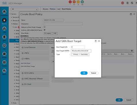
Create Secondary Boot Path through Fabric B
Use the procedures above for Creating a Primary Boot Path through Fabric A to define a secondary boot path through Fabric B.
1. From the vHBAs section of the window, click on Add SAN Boot.
2. In the Add SAN Boot dialog box, specify the vHBA (vHBA-B) for SAN Fabric B. For Type, select the Secondary radio button. Click OK to complete.
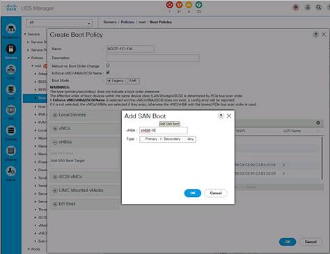
![]() The Add SAN Boot Target under vHBAs will be greyed until this step is complete.
The Add SAN Boot Target under vHBAs will be greyed until this step is complete.
3. From the vHBAs section of the window, click on Add SAN Boot Target.
4. In the Add SAN Boot Target dialog box, specify the Boot Target LUN as ‘0’ for this setup. Specify the ‘primary’ SAN Boot Target WWPN which is the primary controller port reachable through the secondary boot path for this policy. From the table above, WWPN for the Nimble Controller A port (FC2.1) is: 56:c9:ce:90:c3:b3:20:0a. Select ‘Primary’ radio button to specify the Type. Click OK to complete.
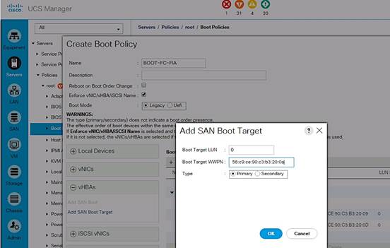
5. In the vHBAs section of the window, click on Add SAN Boot Target a second time to specify the backup SAN target for the secondary boot path.
6. In the Add SAN Boot Target dialog box, specify the Boot Target LUN as ‘0’ for this setup. Specify the ‘secondary’ SAN Boot Target WWPN which is the WWPN of the secondary controller port reachable through the secondary boot path for this policy. From the table above, WWPN for Nimble Controller B port (FC2.1) is: 56:c9:ce:90:c3:b3:20:0E. Specify the Type as ‘Secondary’. Click OK to complete.
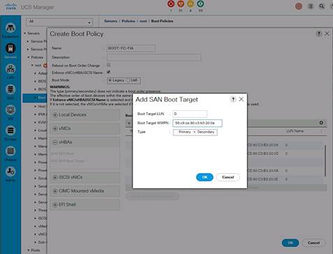
7. A summary view of the configuration is shown below.
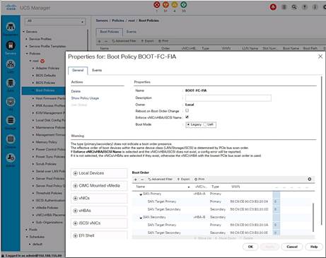
Create Boot Policy using Fabric B as Primary
The second boot policy (BOOT-FC-FIB) will use Fabric B as the primary boot path. The following order of priority is used for booting.
· CD/DVD
· SAN Boot
- Primary Path: HBA-B > FI-B > SAN Fabric B (Cisco MDS-B) à Nimble (A/B)
- Secondary Path: HBA-A > FI-A > SAN Fabric A (Cisco MDS-A) à Nimble (A/B)
Follow the procedures outlined above for Create Boot Policy using Fabric A as Primary to create this boot policy. The resulting configuration for this setup is shown below.
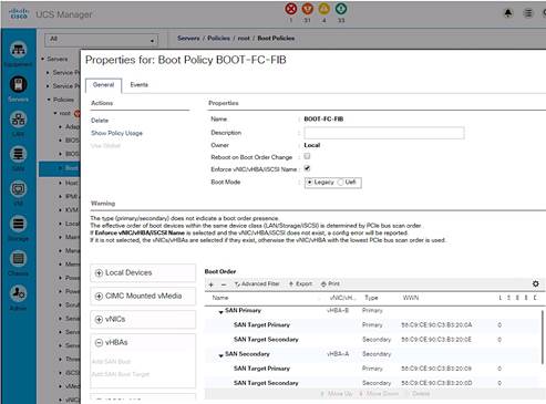
Boot Policies – Summary View
A summary view of the two boot polices created for this setup are shown below.
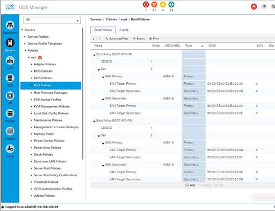
Create Host Firmware Package Policy
Firmware management policies allow the administrator to select the corresponding packages for a given server configuration. These policies often include packages for adapter, BIOS, board controller, FC adapters, host bus adapter (HBA) option ROM, and storage controller properties. To create a firmware management policy for a given server configuration in the Cisco UCS environment, complete the following steps:
1. From Cisco UCS Manager, click on the Servers icon in the navigation pane.
2. Select Policies > root > Host Firmware Packages.
3. Right-click Host Firmware Packages and select Create Host Firmware Package.
4. Enter the name of the host firmware package (for example, HOST-FW-POLICY).
5. Leave Simple selected.
6. Select the package versions for the different type of servers (Blade, Rack) in the deployment (3.1(2b)) for Blade and Rack servers.
7. Click OK twice to complete the host firmware package policy.
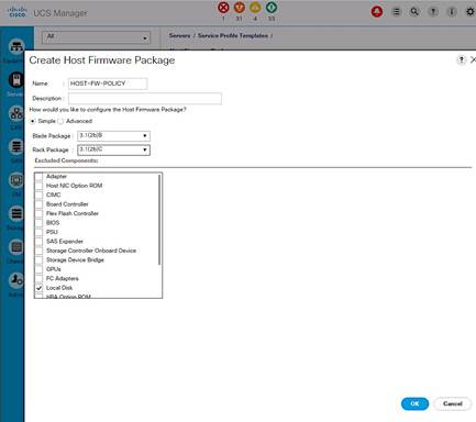
Create Local Disk Configuration Policy
For Cisco UCS servers with no local disks, it is important to create a local disk configuration policy. Complete the following steps to create the policy.
1. From Cisco UCS Manager, click on the Servers icon in the navigation pane.
2. Select Policies > root > Local Disk Configuration Policies.
3. Right-click and select Create Local Disk Configuration Policy.
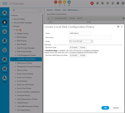
4. Enter local disk configuration policy name (SAN-Boot).
5. Set Mode as No Local Storage from the drop down list.
6. Click OK twice to create the local disk configuration policy.
Create Maintenance Policy
To create a Maintenance Policy for the Cisco UCS environment, complete the following steps:
1. From Cisco UCS Manager, click on the Servers icon in the navigation pane.
2. Select Policies > root > Maintenance Policies.
3. Right-click and select Create Maintenance Policy.
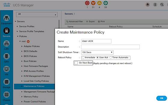
4. Specify a name for the policy (User-ACK).
5. Change the Reboot Policy to User Ack.
6. Click OK twice to create the maintenance policy.
Create Power Control Policy
To create a power control policy on Cisco UCS, complete the following steps.
1. From Cisco UCS Manager, click on the Servers icon in the navigation pane.
2. Select Servers > Policies > root > Power Control Policies.
3. Right-click and select Create Power Control Policy.
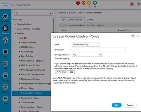
4. Enter the power control policy name (No-Power-Cap).
5. Change the power capping setting to No Cap.
6. Click OK twice to create the power control policy.
Create Server Pool Qualification Policy
To create a server pool qualification policy (optional), complete the following steps.
![]() The same procedure can be used to create policies for other Cisco UCS server models.
The same procedure can be used to create policies for other Cisco UCS server models.
1. From Cisco UCS Manager, click on the Servers icon in the navigation pane.
2. Select Policies > root > Server Pool Policy Qualifications.
3. Right-click and select Create Server Pool Policy Qualification.
4. Enter the name for the policy (UCSB-B200-M4). Click on +Add and select Create Server PID Qualifications from the list.
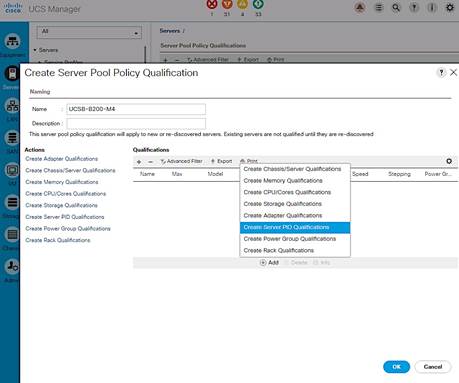
5. Enter the PID for the server from the drop-down list (UCSB-B200-M4).
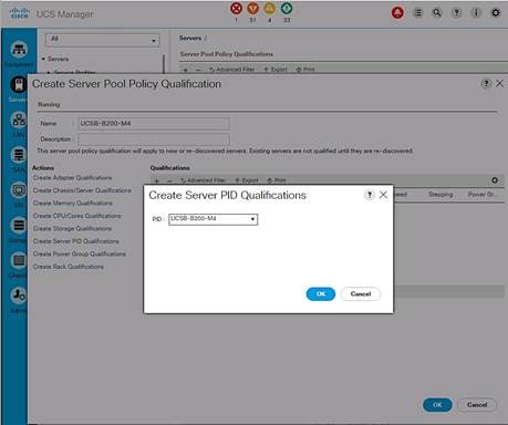
6. Click OK twice to create the server pool qualification policy.
Create vNIC and vHBA Placement Policy
To create a vNIC/vHBA placement policy for Cisco UCS hosts, complete the following steps.
1. From Cisco UCS Manager, click on the Servers icon in the navigation pane.
2. Select Policies > root > vNIC/vHBA Placement Policies.
3. Right-click and select Create Placement Policy.
4. Enter Name of the Placement Policy (VM-Host-Infra).
5. Go to Virtual Slot 1. Click on the associated Selection Preference and select Assigned Only from the drop-down list as shown below
6. Click OK twice to create the placement policy.
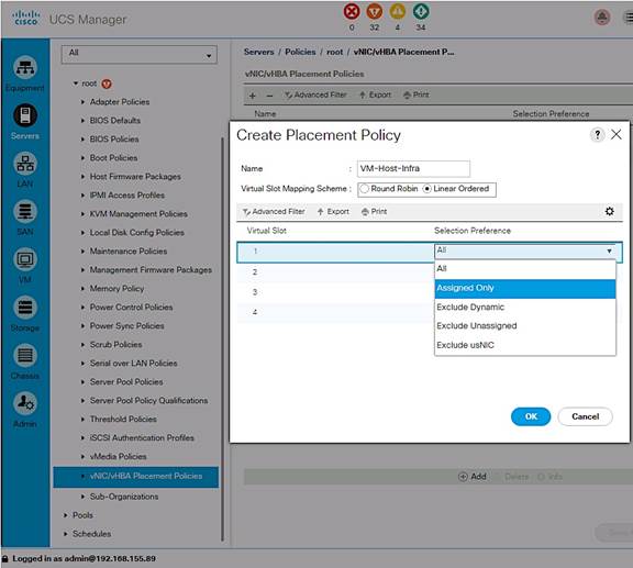
Create Server Pools
Create UUID Suffix Pool
To configure a universally unique identifier (UUID) suffix pool on Cisco UCS, complete the following steps.
1. From Cisco UCS Manager, click on the Servers icon in the navigation pane.
2. Select Servers > Pools > root > UUID Suffix Pools.
3. Right-click and select Create UUID Suffix Pool (UUID-SUFFIX-POOL).
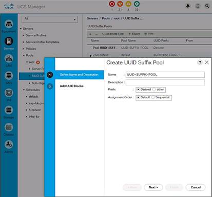
4. Specify a Name for the UUID suffix pool. Click Next.
5. Click [+] Add to add a block of UUIDs.
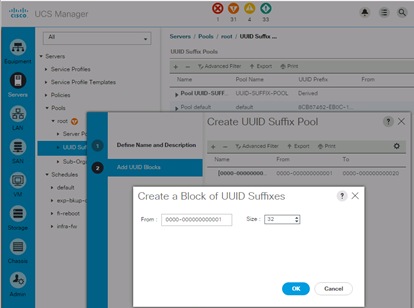
6. The default starting value is used. Specify a block size (32) large enough to support the available server resources.
7. Click OK, click Finish and click OK again to create UUID Pool.
Create Server Pools
To configure Server Pools on a Cisco UCS, complete the following steps.
1. In Cisco UCS Manager, click Servers tab in the navigation pane.
2. Select Pools > root > Server Pools.
3. Right-click and Select Create Server Pool.
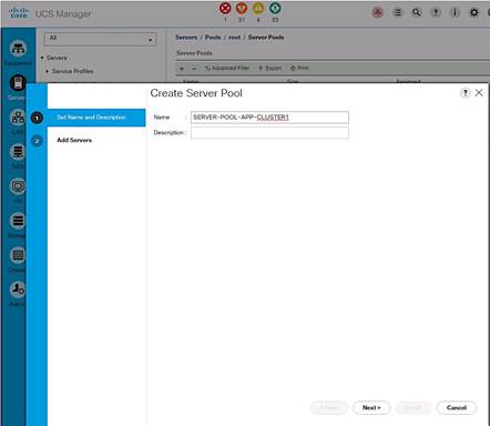
4. Enter name of the server pool (SERVER-POOL-APP-CLUSTER1). Click Next.
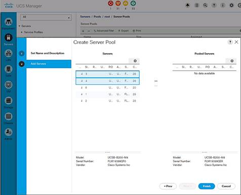
5. Select two (or more) servers to be used for the VMware Application cluster and click >> to add them to the server pool. Click Finish to complete.
Cisco UCS Configuration – SAN
SAN Configuration Workflow
The workflow below shows the configuration required to create vHBA Templates on Cisco UCS servers. The vHBA Templates encapsulate the SAN configuration of servers on Cisco UCS. Two vHBA templates are created in the design for redundancy, one through Fabric A and another through Fabric B. The next sections will cover the configuration of the individual steps in the work flow.
Figure 17 SAN Configuration Workflow
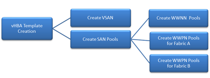
![]() VSAN configuration was completed in an earlier section of this document.
VSAN configuration was completed in an earlier section of this document.
Create SAN Pools
Create WWNN Pools
To configure the necessary World Wide Node Name (WWNN) pools for the Cisco UCS environment, complete the following steps:
1. From Cisco UCS Manager, click on the SAN icon in the navigation pane.
2. Select Pools > root > WWNN Pools.
3. Right-click on WWNN Pools and select Create WWNN Pool.
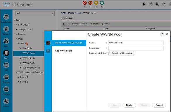
4. Enter the name (WWNN-Pool) of the WWNN pool.
5. (Optional) Specify assignment order as Sequential. Click Next.
6. Click [+] Add to add a block of WWNNs.
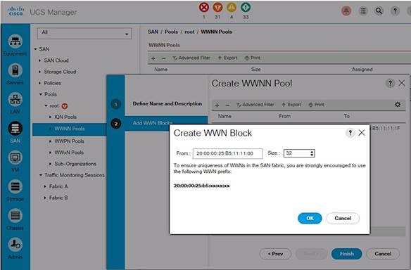
7. Specify a starting block or use the default. The 6th and 7th octet was changed to 11:11 in this setup for troubleshooting purposes to associate the traffic to this UCS domain.
8. Specify a size for the WWNN block large enough to support the server resources.
9. Click OK, click Finish. Click OK again to complete the pool configuration.
Create WWPN Pools
Two World Wide Port Name (WWPN) pools are created in this procedure, one for SAN Fabric A and another for SAN Fabric B. The 7th octet of the starting WWPN is modified to AA and BB to identify the WWPNs as Fabric A and Fabric B addresses respectively. The 6th octet is same as the value (11) used for the WWNN pool above.
Create SAN Fabric A WWPN Pools
To configure the necessary SAN Fabric A WWPN pools for the Cisco UCS environment, complete the following steps:
1. From Cisco UCS Manager, click on the SAN icon in the navigation pane.
2. Select Pools > root > WWPN Pools.
3. Right-click on WWPN Pools and select Create WWPN Pool.
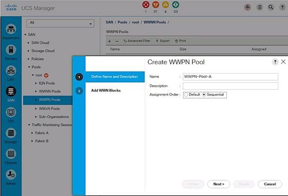
4. Enter the name (WWPN-Pool-A) of the WWPN pool for Fabric A.
5. (Optional) Specify assignment order as Sequential. Click Next.
6. Click [+] Add to add a block of WWPNs.
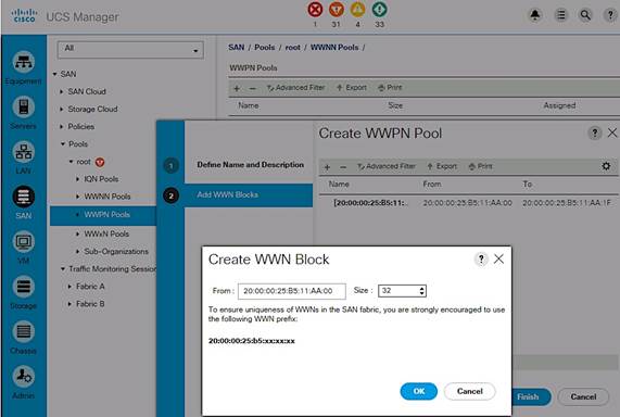
7. Specify the starting WWPN in the block for Fabric A.
8. Specify a size for the WWPN block that is large enough to support the server resources.
9. Click OK, click Finish. Click OK again to complete the pool configuration.
Create SAN Fabric B WWPN Pools
To configure the necessary SAN Fabric B WWPN pools for the Cisco UCS environment, complete the following steps:
1. From Cisco UCS Manager, click on the SAN icon in the navigation pane.
2. Choose Pools > root > WWPN Pool.
3. Right-click on WWPN Pools and select Create WWPN Pool.
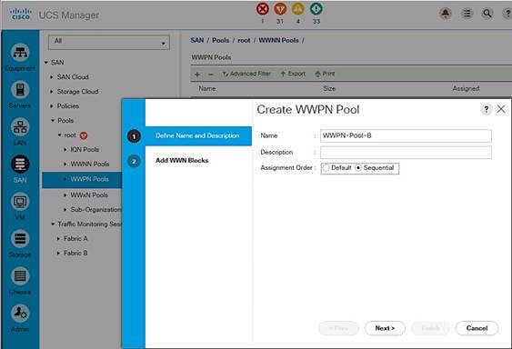
4. Enter the name (WWPN-Pool-B) of the WWPN pool for Fabric B.
5. (Optional) Specify assignment order as Sequential. Click Next.
6. Click [+] Add to add a block of WWPNs.
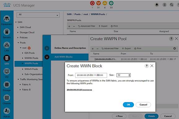
7. Specify the starting WWPN in the block for Fabric B.
8. Specify a size for the WWPN block that is large enough to support the server resources.
9. Click OK, click Finish. Click OK again to complete the pool configuration.
Create vHBA Templates
To create multiple virtual host bus adapter (vHBA) templates, complete the following steps.
Create vHBA Template for Fabric A
From Cisco UCS Manager, click on the SAN icon in the navigation pane.
1. Select Policies > root > vHBA Templates.
2. Right-click on vHBA Templates and select Create vHBA Template.
3. Enter vHBA template name (vHBA-TEMPLATE-A).
4. Click the radio button for Fabric A.
5. For VSAN, select previously created VSAN-A from the drop-down list.
6. Go back to Redundancy Type and select radio button for Primary Template.
7. For Peer Redundancy Template, leave it as <not_set>.
8. For WWPN Pool, select previously created WWPN-POOL-A from the drop-down list.
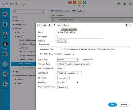
9. Click OK to create the vHBA template.
Create vHBA Template for Fabric B
From Cisco UCS Manager, click on the SAN icon in the navigation pane.
1. Select Policies > root > vHBA Templates.
2. Right-click on vHBA Templates and select Create vHBA Template.
3. Enter vHBA template name (vHBA-TEMPLATE-B).
4. Click the radio button for Fabric B.
5. For VSAN, select previously created VSAN-B from the drop-down list.
6. Go back to Redundancy Type and select radio button for Secondary Template.
7. For Peer Redundancy Template, select vHBA-TEMPLATE-A from the drop down list.
8. For WWPN Pool, select previously created WWPN-POOL-B from the drop-down list.
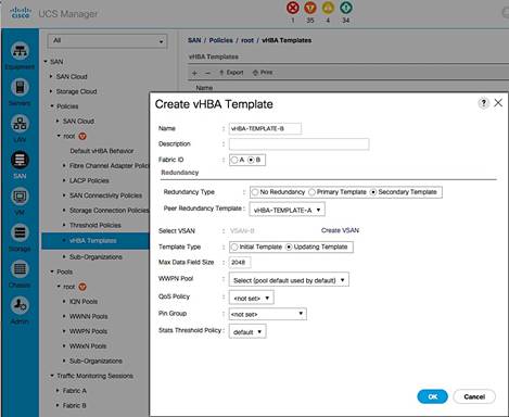
9. Click OK to create the vHBA template.
Create SAN Connectivity Policy
To configure a SAN connectivity policy, complete the following steps.
1. From Cisco UCS Manager, click on the SAN icon in the navigation pane.
2. Select SAN > Policies > root > SAN Connectivity Policies.
3. Right-click and select Create SAN Connectivity Policy.
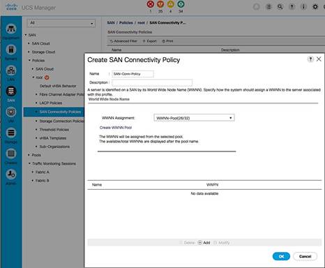
4. In the Create SAN Connectivity dialog box, specify a name for the policy (for example, SAN-Conn-Policy).
5. For WWNN Assignment, select the previously created WWNN-Pool from the list.
6. Click the [+] Add to add a vHBA for Fabric A to the policy.
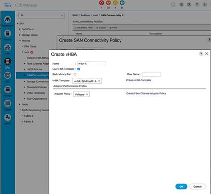
7. In the Create vHBA dialog box, specify a name (vHBA-A) for the vHBA for Fabric A. .
8. Select Use vHBA Template checkbox.
9. Leave Redundancy Pair unselected.
10. In the Adapter Policy list, select VMWare. Click OK.
11. Click the [+] Add again to add a second vHBA for Fabric B to the policy.
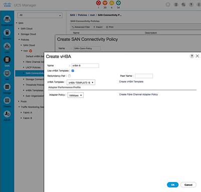
12. In the Create vHBA dialog box, specify a name (vHBA-B) for the vHBA for Fabric B.
13. Select Use vHBA Template checkbox.
14. Leave Redundancy Pair unselected.
15. In the Adapter Policy list, select VMWare. Click OK.
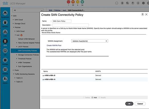
16. Click OK to create the SAN Connectivity Policy and OK again to confirm.
Cisco UCS Configuration - Service Profile Template
In this procedure, two service profile templates are created: one using SAN Fabric A as the primary boot path and a second one using SAN Fabric B.
Create Service Profile Template for Fabric A
To create the service profile template that uses SAN Fabric A as the primary boot path, complete the following steps.
1. From Cisco UCS Manager, click on the Servers icon in the navigation pane.
2. Select Servers > Service Profile Template > root.
3. Right-click on root and select Create Service Profile Template to open the Create Service Profile Template wizard.
4. In the Identify Service Profile Template window, configure the following:
a. Enter a name (SPT-AppVMHost-UFF-FIA) for the template. This template will be configured to SAN boot using Fabric A as the primary path.
b. Select the Updating Template radio button.
c. For UUID Assignment, select the previously configured UUID pool (UUID-SUFFIX-POOL). Click Next.
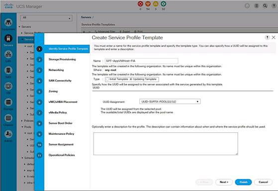
5. In the Storage Provisioning window, configure the following if you have servers with no physical disks. Otherwise, select the default Local Storage Policy
a. Go to the Local Disk Configuration Policy tab.
b. For Local Storage, select the previously configured policy (SAN-Boot). Click Next.
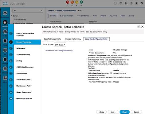
6. In the Networking window, configure the following:
a. For the question regarding LAN connectivity, select the radio button for Use Connectivity Policy.
b. For the LAN Connectivity policy, select the previously configured policy (LAN-Conn-Policy) from the drop down list. Click Next.
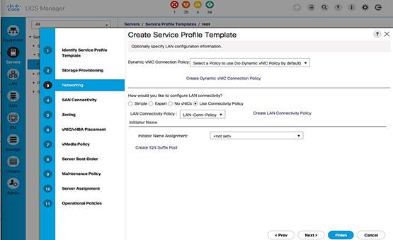
7. In the SAN Connectivity window, configure the following:
a. For the question regarding SAN connectivity, select the radio button for Use Connectivity Policy.
b. For the SAN Connectivity policy, select the previously configured policy (SAN-Conn-Policy). Click Next.
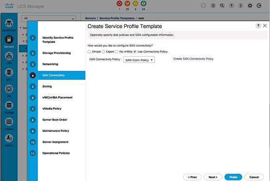
8. In the Zoning window, use the defaults. Zoning is done within the Cisco MDS switches. Click Next.
9. In the vNIC/vHBA Placement window, configure the following:
a. In the Select Placement list, select the previously created policy (VM-Host-Infra).
b. Select vCon1 from the list on the right side and assign the vHBAs/vNICs to the virtual network interfaces policy in the order shown below. Click Next.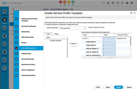
10. In the vMedia Policy window, make no changes. Click Next.
11. In the Set Boot Order window, select the previously created boot policy that uses SAN Fabric A as the primary boot path (BOOT-FC-FI-A). Click Next.
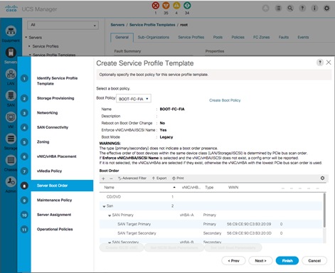
12. In the Maintenance Policy window, select the previously created maintenance policy (User-ACK). Click Next.
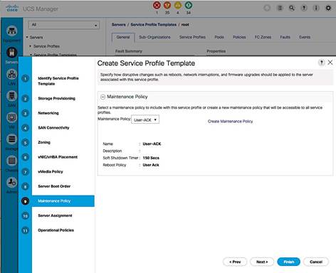
13. In the Server Assignment window, configure the following:
a. For Pool Assignment, select the previously created policy from the list (SERVER-POOL-APP-CLUSTER1).
b. Leave the Power State as UP for when the Profile is applied to a server.
c. For Server Pool Qualification, select the previously created policy from the list (UCSB-B200-M4).
d. Expand the Firmware Management section. For the Host Firmware Package, select the previously selected policy from the list (HOST-FW-POLICY). Click Next.
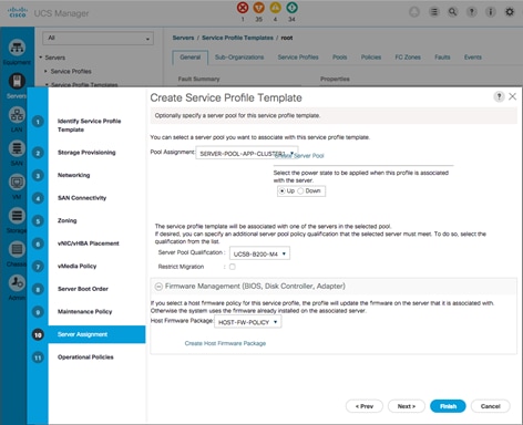
14. In the Operation Policies window, configure the following:
a. For the BIOS Policy list, select the previously configured policy (VM-Host-Infra).
b. Expand Power Control Policy Configuration. For IPMI Access Profile, select the previously configured policy (No-Power-Cap). Click Finish to complete.
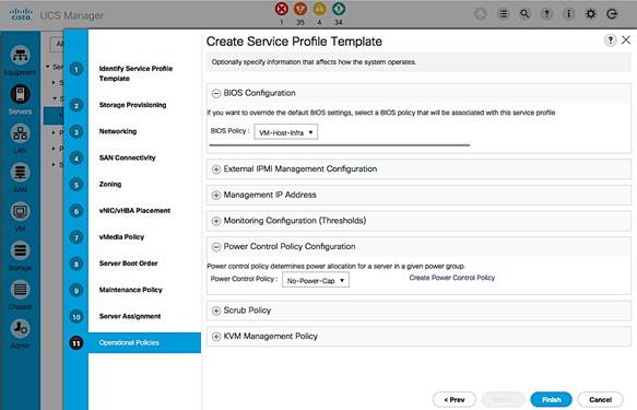
Create Service Profile Template for Fabric B
To create the service profile template that uses SAN Fabric B as the primary boot path, complete the following steps.
1. From Cisco UCS Manager, click on the Servers icon in the navigation pane.
2. Select Servers > Service Profile Templates > root. Expand root.
3. Select the previously created template (SPT-AppVMHost-FIA). Right-click and select Create a Clone.
4. In the dialog box, enter the clone name (SP-AppVMHost-FIB). Click OK.
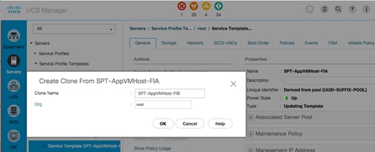
5. Open the newly created service profile template and select the Boot Order tab and Click on Modify Boot Policy.
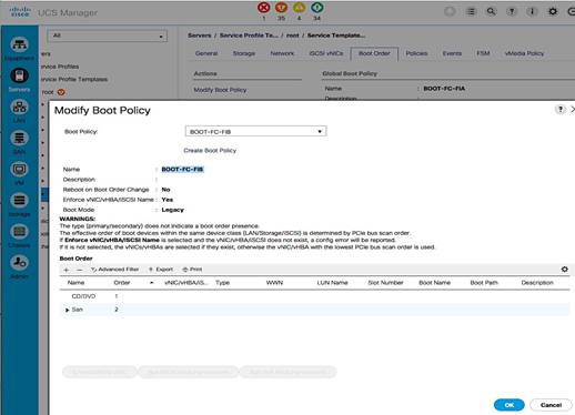
6. In the Modify Boot Policy window, select the previously created boot policy (BOOT-FC-FIB) for Fabric B. Click OK twice.
7. Select the Network tab next and click on Modify vNIC/vHBA Placement.
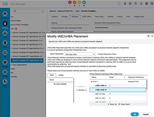
8. In the Modify vNIC/vHBA Placement window, expand vCon 1 and move vHBA-B ahead of vHBA-A in the placement order. Click OK twice to complete.
![]() The Cisco UCS setup is now at the point where the template can be used to deploy new servers using service profiles generated from service profile templates created here.
The Cisco UCS setup is now at the point where the template can be used to deploy new servers using service profiles generated from service profile templates created here.
This section covers the setup procedures for deploying a new server in this solution.
New Host Deployment Workflow
Figure 18 Workflow for Deploying New Hosts
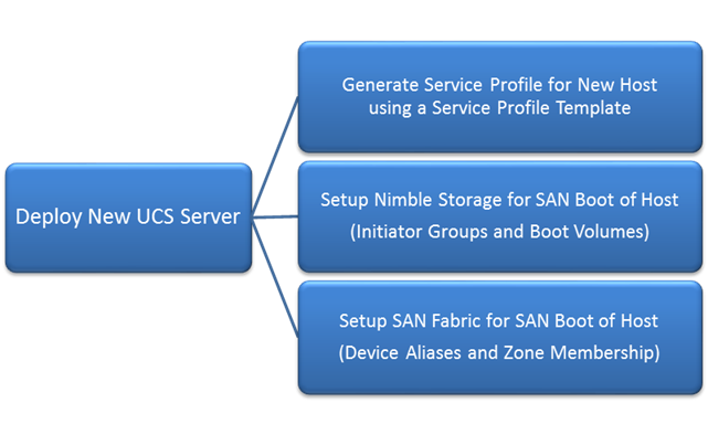
Generate Service Profile for the New Host using a Service Profile Template
Using the service profile template created earlier to generate a service profile for the newly deployed host.
1. From Cisco UCS Manager, click on the Servers icon in the navigation pane.
2. Select Servers > Service Profile Templates > root.
3. Select the Service Profile Template created in earlier steps (SPT-AppVMHost-FIA) that uses SAN Fabric A as the primary path for booting. Right-click on the template and select Create Service Profiles from the menu.
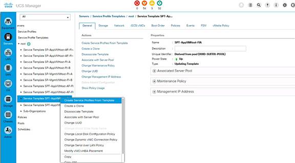
4. Enter the Naming Prefix, the Suffix Starting Number and Number of service profiles instances to create and click OK twice to complete.
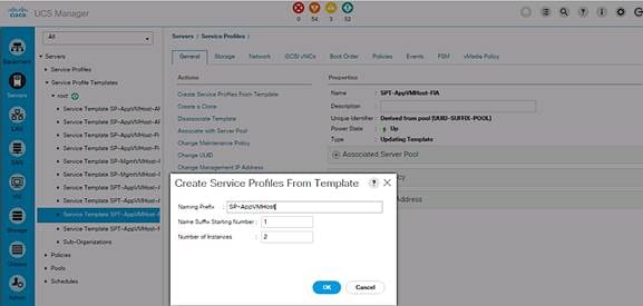
5. For the next host, repeat above steps to create a service profile that will use Fabric B as primary path for traffic. Click OK twice to complete.
6. Verify that the service profile was created and associated. The newly created service profile is automatically associated with the server if the server is part of the server pool defined in the template.
7. Create service profiles for all the servers in the server pool. The figure below shows the servers used for validation in this design.
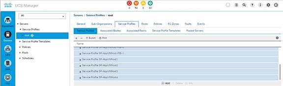
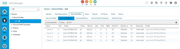
8. (Optional) Choose each newly created service profile and enter the server host name or the FQDN (CVD-UFF-Host1) in the User Label field in the General Tab. Click Save Changes to map the server host name to the service profile name.
Setup Nimble Storage Array for SAN Boot of Host
This section provides instruction on how to create Nimble Storage volumes and initiator groups for FC SAN boot of the new host.
Collect Initiator WWPNs from the Host Service Profile
1. Login to Cisco UCSM using a web browser – use the Cisco FI cluster IP address and admin username and password to log in.
2. Click on the Servers icon. Select Servers > Service Profiles > root and select the Service Profile for the new host. Expand the profile and select vHBAs.
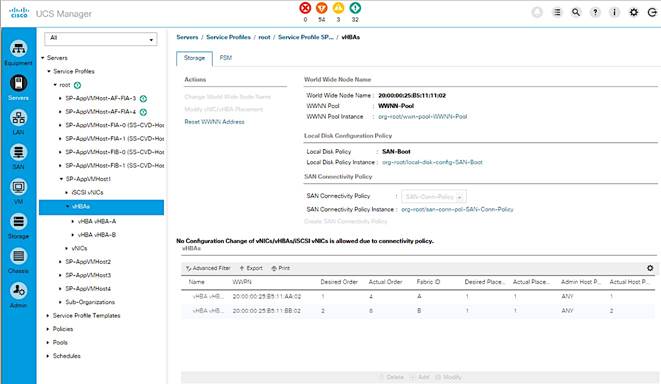
3. Collect the WWPN information are for both vHBA-A and vHBA-B.
4. Repeat the above steps for every new host being deployed.
Create Initiator Group for Host
Using the host’s WWPN information collected in the previous step, create an initiator group for the host to enable access to volumes on Nimble Storage.
1. Login to the Nimble Storage GUI using a web browser.
2. Navigate to Manage > Initiator Groups. Click on Create.
3. Fill out the form below using the WWPNs collected in previous step.
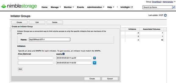
Create Boot Volumes for Host
1. Login to the Nimble Storage GUI using a web browser. Navigate to Manage > Volumes. Select New Volume. Fill out the form as shown below. 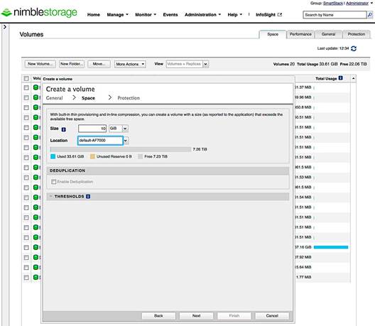
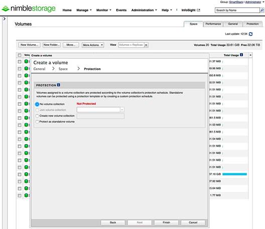
2. Select the host’s initiator group name that you created in previous step. Also, note that the LUN ID will default to 0 which matches the boot policy for this Service Profile.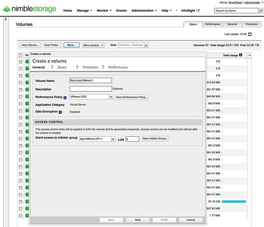
3. Repeat these steps for every new host deployed from a Service Profile. Note, that each initiator group and each volume will be unique.
Setup SAN Fabric for SAN Boot of Host
Add the WWPNs of the newly deployed hosts to the VSANs of both Cisco MDS switches for reachability to array volumes. Repeat these steps for each new host deployed.
Configure Device Aliases for the New Host
Cisco MDS-A
1. Create device-aliases for the host WWPN from above and save the configuration.
device-alias confirm-commit enable
device-alias database
device-alias name AppVMHost-UFF-1 pwwn 20:00:00:25:b5:11:aa:02
device-alias commit
2. Save the configuration.
copy run start
Cisco MDS-B
1. Configure the device-aliases for the above WWPNs above and commit it as follows.
device-alias confirm-commit enable
device-alias database
device-alias name AppVMHost-UFF-1 pwwn 20:00:00:25:b5:11:bb:02
device-alias commit
2. Save the configuration.
copy run start
![]() The device aliases for the controllers on the arrays in the Unified Flash Fabric were created in an earlier section of this document.
The device aliases for the controllers on the arrays in the Unified Flash Fabric were created in an earlier section of this document.
Create Zones and Zoneset for the New Host
The host is setup below to access both controllers on both arrays though only one array is used for SAN Boot. This is to allow access to other volumes that might reside on either array.
Cisco MDS-A
1. Create Host Zones for each host.
zone name AppVMHost-UFF-1 vsan 4091
member device-alias AppVMHost-UFF-1
member device-alias AF7k-CNTLA-FC1
member device-alias AF7k-CNTLA-FC5
member device-alias AF7k-CNTLB-FC1
member device-alias AF7k-CNTLB-FC5
member device-alias CS5k-CNTLA-FC1
member device-alias CS5k-CNTLA-FC5
member device-alias CS5k-CNTLB-FC1
member device-alias CS5k-CNTLB-FC5
2. Create Zoneset and Add Zones to it.
zoneset name Fabric-A vsan 4091
member AppVMHost-UFF-1
3. Activate zoneset and enable distribution.
zoneset activate name Fabric-A vsan 4091
4. Save the configuration.
copy run start
Cisco MDS-B
1. Create Host Zones.
zone name AppVMHost-UFF-1 vsan 4092
member device-alias AppVMHost-UFF-1
member device-alias AF7k-CNTLA-FC2
member device-alias AF7k-CNTLA-FC6
member device-alias AF7k-CNTLB-FC2
member device-alias AF7k-CNTLB-FC6
member device-alias CS5k-CNTLA-FC2
member device-alias CS5k-CNTLA-FC6
member device-alias CS5k-CNTLB-FC2
member device-alias CS5k-CNTLB-FC6
2. Create Zoneset and Add Zones to it.
zoneset name Fabric-B vsan 4092
member AppVMHost-UFF-1
3. Activate zoneset and enable distribution.
zoneset activate name Fabric-B vsan 4092
4. Save the configuration.
SAN Boot and Install of ESXi on Host
This section provides detailed instructions for installing VMware ESXi 6.5 in this solution. After the procedures are completed, the ESXi hosts will be provisioned.
![]() Several methods exist for installing ESXi in a VMware environment. These procedures focus on how to use the built-in Keyboard, Video, Mouse (KVM) console and virtual media features in Cisco UCS Manager to map remote installation media to individual servers and connect to their boot volumes. A Cisco custom ESXi 6.5 ISO file is first downloaded from VMware and positioned on the Windows machine used to KVM console into the Cisco UCS server. The custom image that includes the necessary Cisco drivers are used in this deployment. These drivers may need to be upgraded but using the custom image ensures a minimum supported version.
Several methods exist for installing ESXi in a VMware environment. These procedures focus on how to use the built-in Keyboard, Video, Mouse (KVM) console and virtual media features in Cisco UCS Manager to map remote installation media to individual servers and connect to their boot volumes. A Cisco custom ESXi 6.5 ISO file is first downloaded from VMware and positioned on the Windows machine used to KVM console into the Cisco UCS server. The custom image that includes the necessary Cisco drivers are used in this deployment. These drivers may need to be upgraded but using the custom image ensures a minimum supported version.
KVM Console into Host from Cisco UCSM Web Interface
1. Login to Cisco UCSM using a web browser using the IP address of the Cisco UCS FI cluster. Login using administrator (for example, admin) account and password.
2. Download the Cisco Custom ISO for ESXi from the VMware website.
3. From the main Cisco UCSM menu, click Servers tab.
4. Select Servers > Service Profiles > root.
5. Select the host’s service profile (for example, SP-AppVMHost1) and right-click.
6. Select KVM Console from the menu to open a console window into the host.
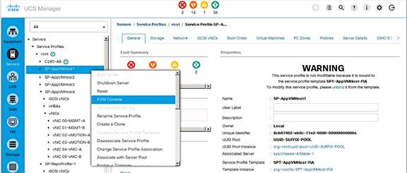
Prepare Host for ESXi Install
1. In the KVM console window, select Virtual Media from the top menu. Select Activate Virtual Devices.
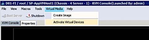
2. In the Virtual Media Session window, select Accept this Session and click Apply.
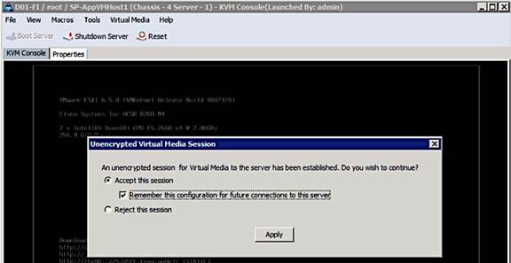
3. Select Virtual Media again from the top menu and pick the Map CD/DVD option.
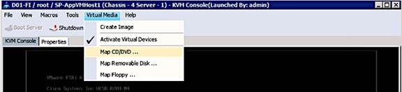
4. In the Virtual Media – Map CD/DVD window, click on Browse to select a previously downloaded custom Cisco ESXi ISO file from vmware.com.
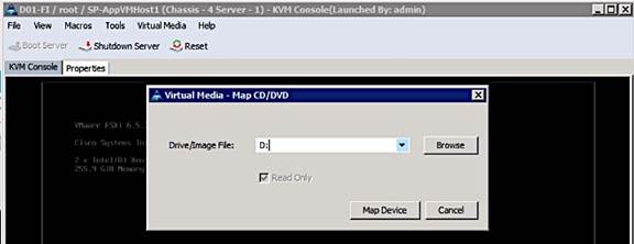
5. Click the Map Device button to map the selected Custom Cisco ESXi ISO image.
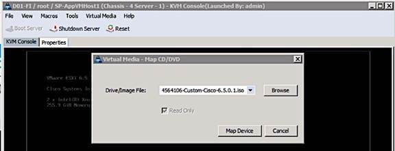
6. Click on Reset from the KVM console menu to trigger a power cycle. Click OK 3 times to accept the warning and reboot the host.
7. Select the Custom Cisco ESXi image from the menu below. Press Enter to proceed.
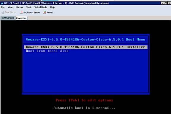
8. After the ESXI installer loads, proceed to the next section to install the ESXi image.
Install ESXi
1. When the server boots, the host detects the presence of the ESXi installation media and loads the ESXi installer as shown below. Press Enter to Continue.
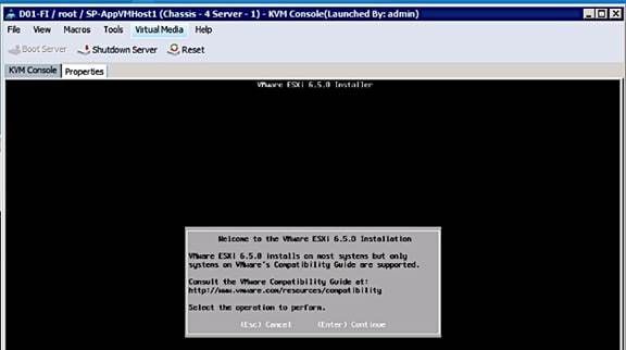
2. Read and accept the end-user license agreement (EULA). Press F11 to Accept and Continue.
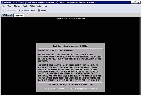
3. Select the Nimble Boot Volume that was previously created for the host. Press Enter to Continue with installation.
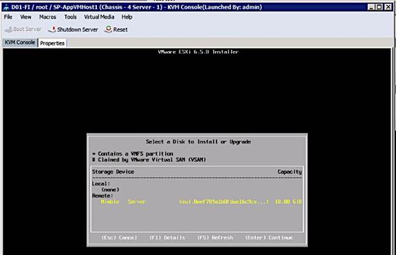
4. When prompted, select the appropriate keyboard layout (for example, US Default) in the pop-up window and press Enter to Continue.
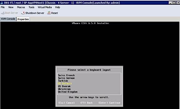
5. When prompted, enter the root password for the host in the pop-up window and press Enter to Continue.
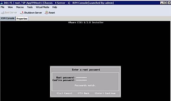
6. In the Confirm Install pop-up, Press F11 to Install and continue.
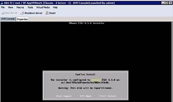
7. A progress bar will be displayed to show the ESXi installation progress on the server’s boot volume on Nimble.
8. When the install is complete, the following window pops-up requesting the removal of the installation media. Select Virtual Media from the top menu and click on Activate Virtual Devices. Click Yes to un-map the Virtual Media. Press Enter to Reboot host.
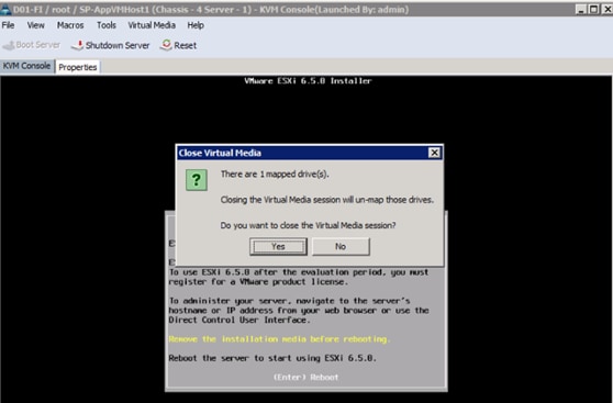
9. As the server boots, verify that the Nimble array is reachable through both SAN fabrics. On the active controller (Nimble Controller A), FC1 and FC5 ports connect to SAN Fabric A while FC2 and FC6 ports connect to SAN Fabric B. Though the controllers have dual connections to each fabric, during boot up, ESXi will only attempt to reach the first controller port (FC1, FC2) through each Fabric.
10. WWPN info for FC1 (56:c9:ce:90:c3:b3:20:09) and FC2 (56:c9:ce:90:c3:b3:20:0a) ports on the active controller can be found as follows.
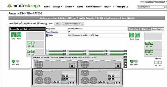
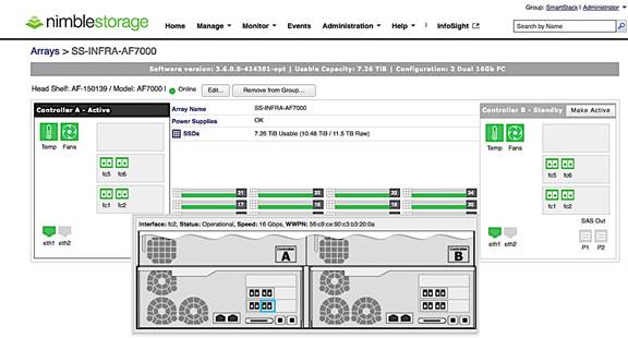
11. Host can reach the active controller’s FC1 port through SAN Fabric A as shown below.
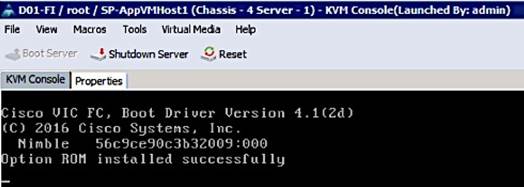
12. Host can reach the active controller’s FC2 port through SAN Fabric B as shown below.
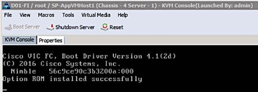
13. The Server boots the ESXi image from the Nimble boot volume and is now ready to be configured.

Setup ESXi Host for IP Management
1. Once the host comes up, press F2 on the KVM console to Customize System/View Logs and login as root.
2. Navigate to the Configure Management Network option and press Enter.
3. From the Configure Management Network menu, select Network Adapters and verify that the correct vmnic for management is selected. Only one vmnic needs to be selected, the second one can be added from vCenter. Press Enter.
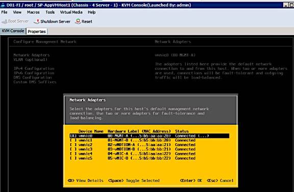
4. (Optional) From the Configure Management Network menu, navigate to VLAN and press Enter. Enter the in-band management VLAN ID (VLAN 12) and press Enter.
5. From the Configure Management Network menu, select IPv4 Configuration option and press Enter. Using the space bar key, select Set Static IPv4 Address and Network Configuration option. Enter the Management IP address (for example, 192.168.155.111), subnet mask (for example, 255.255.255.0) and default gateway for the ESXi host (for example, 192.168.155.1). Press Enter to accept the changes to the IP configuration.
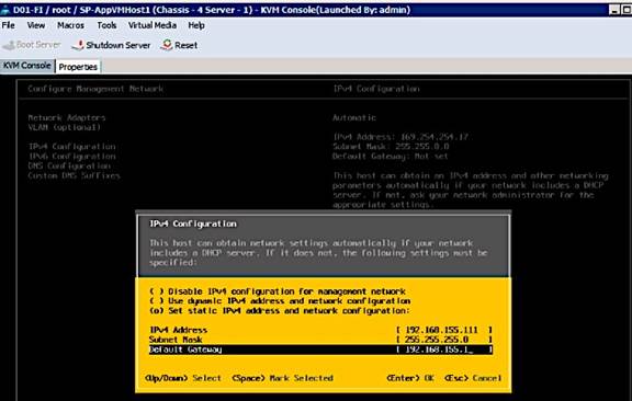
6. If IPv6 is not used for management, disable it. From the Configure Management Network menu, select IPv6 Configuration option and press Enter. Using the spacebar, select Disable IPv6 (restart required) and press Enter to accept changes.
7. From the Configure Management Network menu, select DNS Configuration option and press Enter. Enter the IP address of the primary DNS server and the secondary DNS server (optional). Enter the fully qualified domain name (FQDN) for the first ESXi host. Press Enter to accept the changes to the DNS configuration. Press Enter to accept the changes to the DNS configuration.

8. Press Esc to exit the Configure Management Network submenu. Press Y to Confirm changes and reboot host.
9. The ESXi host reboots. After reboot, press F2 and log back in as root.
10. Navigate to the Select Test Management Network to verify the management network is set up correctly. Specify addresses to ping or hostname to resolve and press Enter to run the test. Press Enter to exit the test window.
11. (Optional) Navigate to Troubleshooting Options to enable/disable SSH or other troubleshooting options.
12. From the Press Esc to log out of the KVM console. The host is now ready to be added to vCenter.
Provision New Host without vCenter
This section covers the minimal setup required on a host before VMware vCenter is deployed. The procedures outlined here would typically apply to management hosts where vCenter, AD/DNS, NTP and other basic infrastructure services will eventually be deployed. Once vCenter is deployed, provisioning of additional management hosts and application VM hosts will be done through vCenter. The necessary configuration is done by directly accessing the host and is summarized below.
· Access Host using vSphere web client
· Enable NTP on the hosts
· Add vSphere Networking
· Mount necessary datastores
· Update Host FNIC and ENIC drivers if needed
· Install Nimble Connection Manager (NCM)
![]() If VMware vCenter is already deployed, use the steps outlined in the section titled: Add Host to vCenter to provision a new host.
If VMware vCenter is already deployed, use the steps outlined in the section titled: Add Host to vCenter to provision a new host.
Access Host Directly using vSphere Web Client
If this a new environment without an existing vCenter running to manage the hosts, use the following steps to directly access the newly deployed host to do the initial configuration tasks.
1. Using a web browser, navigate to the IP address of the newly deployed host (192.168.155.111)
2. Enter root for the username.
3. Enter the root password.
4. Click Login in to connect and provision the host.
5. Repeat the steps for each host in the deployment or until vCenter is deployed to manage the hosts.
Enable NTP on Host
1. Using vSphere web client, login to the host using its IP address and root account.
2. From the left navigation bar, select Manage > System > Time & Date > Edit settings.
3. In the Edit Time Configuration dialog box for the host, select the radio button to Use Network Time protocol (Enable NTP Client).
4. Specify the NTP Service Startup Policy to Start and Stop with the host.
5. Specify the NTP server to use.
6. Click OK to accept the configuration and start NTP service.
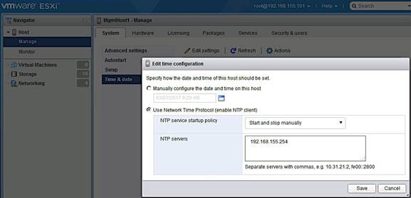
Add vSphere Networking
To add the minimally required networking to get a host up and running to deploy vCenter and other key VMs, complete the following steps. Any remaining networking setup on the host can be done once vCenter is deployed.
1. From vSphere Web Client, login to vCenter and select the host in the inventory.
2. From the left navigation bar, select Networking. Right-click and select Add VMkernel NIC. In the Add VMkernel NIC window, specify the relevant settings. Click Create.
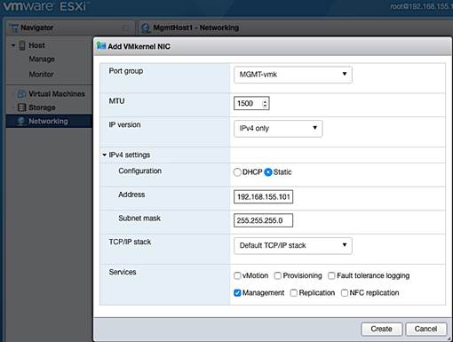
3. Remaining configuration can be done once the host is being managed through vCenter.
Mount necessary Datastores
To add the minimally required datastores to get a host up and running to deploy vCenter and other key VMs, complete the following steps. Any remaining setup can be done once vCenter is deployed.
1. From vSphere Web Client, login to vCenter and select the host in the inventory.
2. From the left navigation bar, select Storage > Adapters > Rescan.
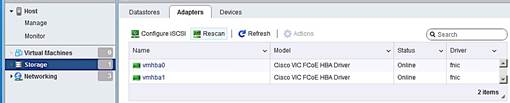
3. Select Datastores tab and click on New datastore icon.
4. In the New datastore dialogue box, select the creation type as a new VMFS datastore.
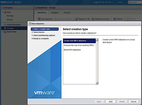
5. For select device, specify a datastore name and the storage device/LUN to associate with.
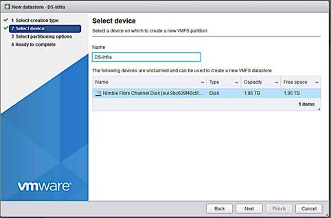
6. Select partitioning options.
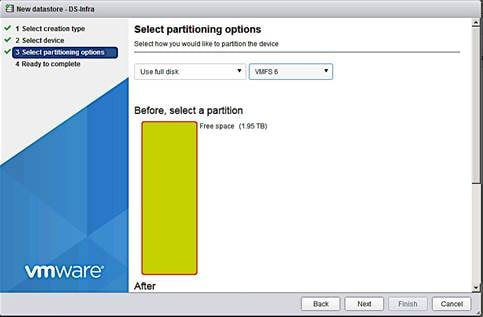
7. Review settings and click Finish to complete.
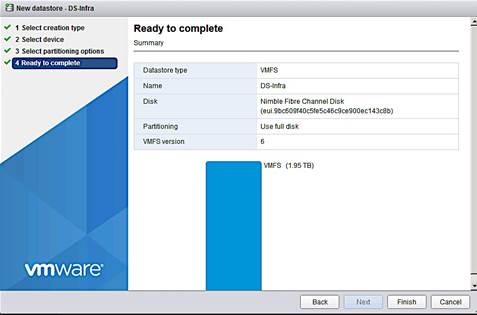
Update FNIC and ENIC Drivers on ESXi Host
The VMware ESXi ISO and (sometimes) Cisco Custom ESXi ISO available from vmware.com may not have the latest FNIC and ENIC drivers that are recommended per the Cisco UCS Hardware and Software Interoperability matrix. If an upgrade is necessary, use the following procedure to identify, download and install the latest supported drivers.
1. Use either of the following methods to determine the latest drivers that are supported at the time of deployment.
a. Search http://www.cisco.com for the “Hardware and Software Interoperability for UCSM Managed Servers” document. Find the document associated with the UCSM version to find the latest drivers required.
b. Use the UCS Hardware and Software Compatibility Tool to specify the server and OS details and get the latest recommendations.
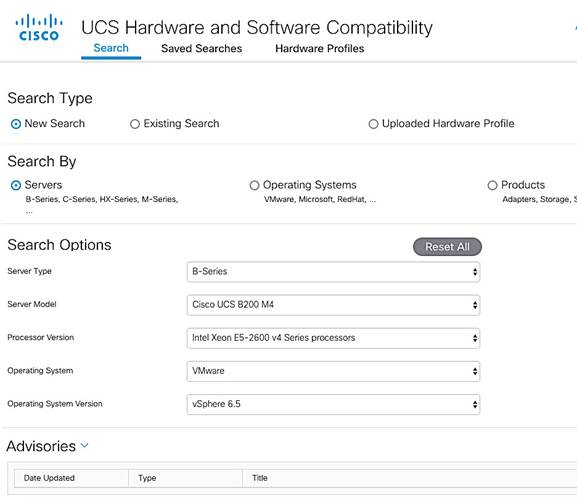
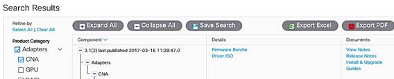
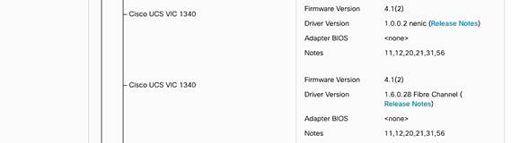
2. To download and install the drivers, follow one of the following the procedures.
a. Use the link specific to the UCSM version running (also provided at the beginning of the Interoperability document). UCSM 3.1(2) Driver ISO can be downloaded here. Open the ISO and select Network > Cisco > VIC > ESXi_6.5 folder and follow the directions to get the network driver and associated release notes. Do the same for storage drivers by going to Storage > Cisco > VIC > ESXi_6.5 folder.
b. Drivers can also be downloaded from vmware.com à Search for “download cisco enic/fnic drivers” to find the drivers.
3. To install the drivers, follow the procedures outlined in the Install guide for the model of Cisco VIC used. The Install Guide can be found as follows.
a. From http://www.cisco.com, browse to Support à Products by Category à Servers - Unified Computing.
b. From Servers - Unified Computing, navigate to Server Software and Additional Products à UCS Virtual Interface Card. Select Install and Upgrade Guides.
c. Select UCS Virtual Interface Card Drivers for ESX Installation Guide and follow the download procedures outlined in the document to download and install Cisco VIC drivers for ESXi.
4. To manually upgrade the drivers on a single host, use the following procedure.
a. Extract the contents of the driver zip file, and identify the *.vib file.
b. From VMware vSphere web client, select the host and the datastore to upload the drivers to. If multiple hosts are being upgraded, use a datastore accessible by all hosts to avoid having to upload drivers to upgrade each host.
c. Click on Browse Files icon and then the Upload icon to upload the *.vib file to the datastore. 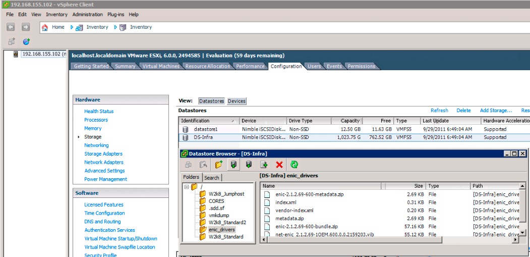
d. Select host and right-click to Enter Maintenance mode before the upgrade. Click Yes to Confirm and OK to acknowledge the Warning.
e. SSH into the ESXi host and verify current versions of drivers. install the driver using the following commands.
esxcli software vib list | grep CSCO (to see all Cisco drivers)
esxcli software vib list | grep enic (to see all network drivers)
esxcli software vib list | grep fnic (to see all storage drivers)
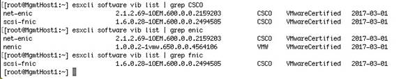
f. Install the driver using the following commands. Repeat for each driver being installed.
esxcli software vib update –v /vmfs/volumes/<datastore_name>/<driver_name>
If you get an error saying ‘Could not find a trusted signer’, use the ‘--no-sig-check’ option.
esxcli software vib update –v /vmfs/volumes/<datastore_name>/<driver_name> --no-sig-check
g. Repeat for each driver being installed. Reboot from vSphere client and exit maintenance mode.
Install Nimble Connection Manager (NCM)
NCM software is used to enable optimal configuration such as setting up multipathing correctly, queue depth, timeout values and so on. The procedure assumes the host can access Nimble’s Infosight website. Alternatively, the image can be downloaded and positioned locally and installed. To deploy NCM on hosts, complete the following steps.
1. Enable SSH (if not enabled already) on the host. This can be done via vSphere client or via KVM console into the host. From the KVM console, press F2 to Customize System/View Logs, select Troubleshooting Options > Enable/Disable SSH.
2. SSH into the hosts and put host in maintenance mode.
esxcli system maintenanceMode set --enable true
3. Download and install NCM software on host. Execute the following command.
esxcli software vib install -d –-no-sig-check https://update.nimblestorage.com/esx6.5/ncm
4. If NCM software is already installed, attempting to reinstall it will skip the install as shown below. For a new host, the NCM images downloaded would be displayed in the “VIBs Installed:” row. You can see what Nimble VIBs are currently install by running the “esxcli software vib list | grep Nimble” command.
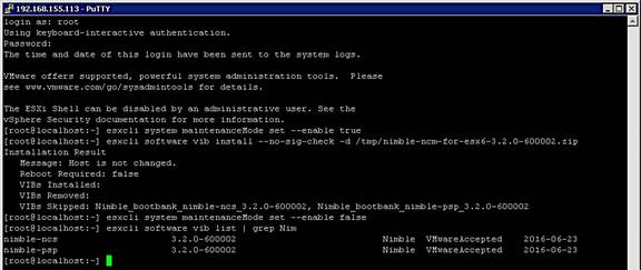
5. Reboot host from VMware vSphere client and enable SSH to log into the host and verify that NCM is installed.
6. Take the host out of maintenance mode and disable SSH (optional).
7. Go to section on Verify Storage Post-NCM Install in a following to confirm storage setup using NCM.
Optional: Deploy VMware vCenter Appliance 6.5
The procedures outlined in this section will install VMware vCenter Server Appliance (VCSA) version 6.5 on a Cisco UCS server to manage the deployment.
![]() The procedures below assume that an existing vCenter 6.0 VCSA will be upgraded to vCenter 6.5. Other install options can be selected using the same VCSA ISO. Skip this section if an existing VMware vCenter environment will be used as is to manage the Cisco-Nimble solution.
The procedures below assume that an existing vCenter 6.0 VCSA will be upgraded to vCenter 6.5. Other install options can be selected using the same VCSA ISO. Skip this section if an existing VMware vCenter environment will be used as is to manage the Cisco-Nimble solution.
Pre-requisites
The following items are needed for the installation.
1. A virtual machine or physical server/PC to initiate download of VCSA ISO files from vmware.com.
2. FTP server to download the ISO files to if different from the above server/PC.
3. A networked client machine (running Mac/Windows/Linux) to mount the ISO and run the GUI installer – for optimal performance, the client OS must meet the minimal requirements outlined in the Preparing for Deployment of vCenter Server Appliance section of vSphere 6.5 documentation.
4. Verify the networked client machine in Step3 can reach the UCS server where vCenter will reside.
Download vCenter Server Appliance (VCSA) ISO from VMware
To download VMware vCenter Server Appliance, complete the following steps:
1. From a server/PC, use a browser to download VMware vCenter Server Appliance installer ISO from VMware Web site at https://my.vmware.com/web/vmware/downloads.
2. Specify a local location to download the ISO to (FTP server or local server/PC).
Install vCenter Server Appliance
To install vCenter 6.5 appliance VM, complete the following steps:
1. Mount VCSA ISO from the client machine and open the ISO.
2. Open the vcsa-ui-installer folder to use the GUI Installer.
3. Open the OS (linux/mac/windows) folder that the client machine uses. Click on the Installer application to open the GUI installer.
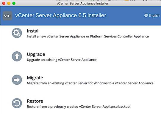
4. Click on Install for a new/fresh install, Upgrade to upgrade an existing vCenter 6.x or below environment and Migrate to migrate to a VCSA from a windows based vCenter. In this setup, the management cluster had an existing vCenter 6.0 setup so the Upgrade option was selected.
![]() For a fresh install of VCSA VM, the networking and storage should be first setup by directly accessing the host using vSphere web client.
For a fresh install of VCSA VM, the networking and storage should be first setup by directly accessing the host using vSphere web client.
5. Verify before proceeding that the Installer client machine has IP reachability to the UCS server or vCenter environment that manages the existing vCenter VM being upgraded/ migrated.
6. In the vCenter Server Appliance Installer GUI, on the Introduction screen, review the information and click Next.
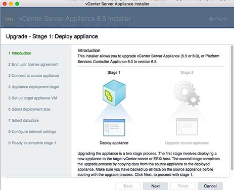
7. Read and accept the End User License Agreement, and click Next.
8. On the Connect to source appliance screen, specify the IP address of the appliance being upgraded or host and associated information. Both are provided here. Click Next.
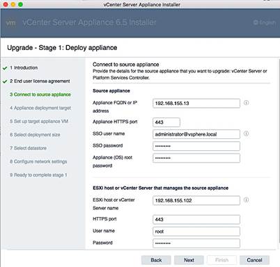
9. On the Appliance deployment target screen, specify the Center Server Appliance or host IP and related info as shown below. Click Next.
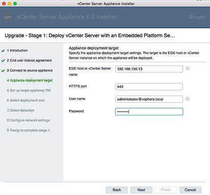
10. In the Select folder screen, select the datacenter and click Next.
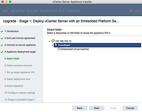
11. In the Select Compute Resource screen, select the appropriate cluster (SS-Mgmt) within the datacenter and click Next.
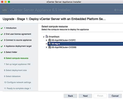
12. In the Setup Target Appliance VM screen, specify the root password and click Next.

13. In the Select Deployment Size screen, select the size that matches your deployment, and click Next.
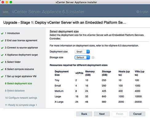
14. In the Select datastore screen, select a datastore location for the VM configuration and virtual disks (DS-Infra), and click Next.
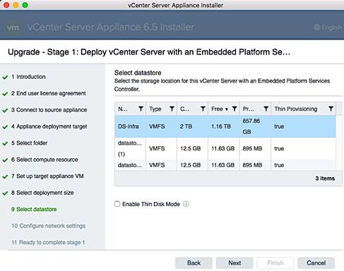
15. In the Configure Network Settings screen, specify the management port group, temporary IP address to use during upgrade/migration, default gateway and DNS information. Click Next.
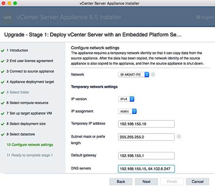
16. Review settings and click Finish to start the upgrade process.
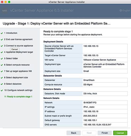
17. The vCenter appliance installation will take few minutes to complete Stage 1 of the process. A status bar will display progress as shown below.
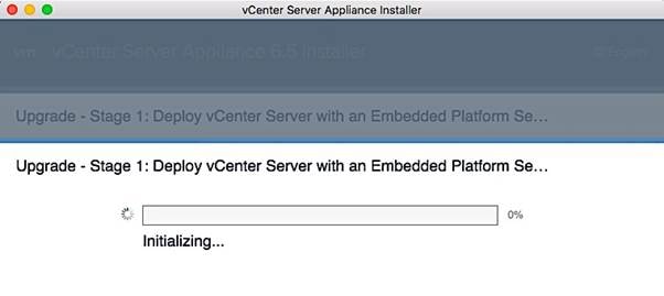
18. When complete, begin Stage 2 of the process using the GUI Installer. In the Introduction screen, select Deploy/Upgrade – Upgrade is chosen in this case.
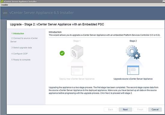
19. A pre-upgrade check runs at this point and may result in a pop-up window as shown below. Review all the results – you can proceed with errors but can with Warnings. Click Close to continue.
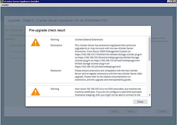
20. In the Select Upgrade Data screen, select the data associated with the source vCenter to be migrated and click Next.
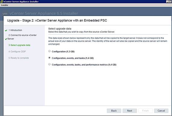
21. In the Configure CEIP screen, decide if you want to join the Customer Experience Improvement Program (CEIP) program and click Next.
22. In the Ready to complete screen, review the settings and click Finish to start Stage 2 of the process.
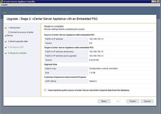
23. The status of the upgrade process will be shown using progress bars as each step completes.
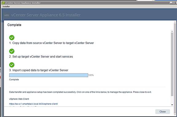
![]()
![]()
24. Click on the vCenter link at the bottom of the above status window to start managing the environment using vCenter 6.5.
Log into vSphere Web Client
1. From the VMware vCenter Installer window, download
2. Using a web browser, navigate to https://192.168.155.13:9443/vsphere-client/
3. Enter the username (administrator@vsphere.local) and associated password. Click Login.
4. Now you can do some basic setup of the VCSA using the web client.
You can now finish vCenter setup and start configuring the VMware vSphere environment.
Join Active Directory Domain
Use the procedures in this section to authenticate vCenter accounts using an existing Active Directory (AD) infrastructure.
1. Use a web browser and navigate to vCenter (https://<vcenter_ip>). Click on vSphere Web Client(Flash) to login into vCenter.
2. Login using an administrator account (administrator@vsphere.local).
3. Navigate to Administration > System Configuration > Nodes and select the vCenter instance.
4. Click on the Manage tab > Settings > Advanced > Active Directory and click on the Join button. In the Join Active Directory window, specify the AD domain name and account info and click OK.
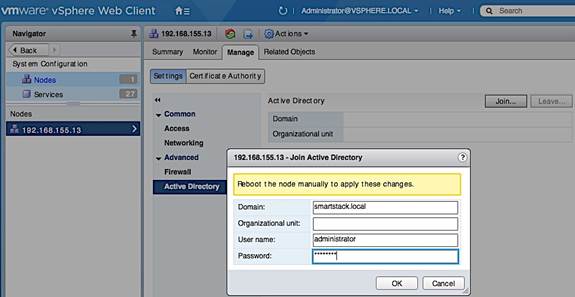
5. Right-click on the vCenter (192.168.155.13) and select Reboot to restart the vCenter instance. Provide a reboot reason. Reboot will take a few minutes.
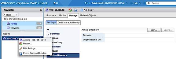
6. Log back into vCenter. Click on the Manage tab > Settings > Advanced > Active Directory. If the join is successful, AD information will be populated and Join button will be greyed out.
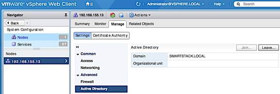
7. Navigate to Administration > Single Sign-On > Configuration. Click on the Identity Sources tab, followed by green [+] to add Identity Source. In the Add Identity Source pop-up window, select the radio button for Active Directory (Integrated Windows Authentication). Click Next.
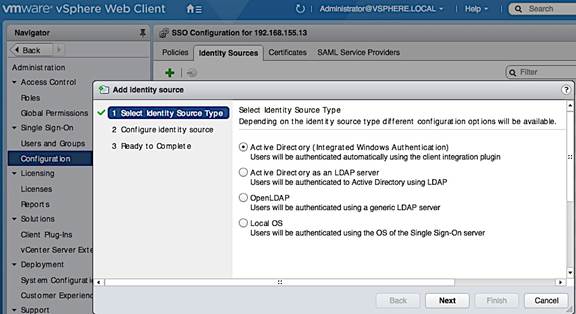
8. In the Configure Identity screen, the Active Directory domain should be filled in. Leave Use machine account checked and click Next.
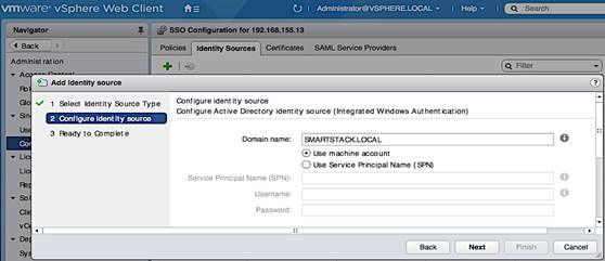
9. Review changed and click Finish to complete. You should now see your Active Directory domain appear in the Identity Sources list.
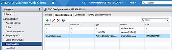
10. Navigate to Administration > Access Control > Global Permissions > Manage. Click on the green [+] button to add users or groups. In the Global Permission Root- Add Permission pop-up window, at the bottom of Users and Groups, click on the Add button.
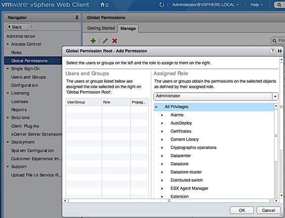
11. In the Select Users/Groups window, select your AD domain and Domain Admins from the Users/Groups list. Click on the Add button, followed by the Check Names button. Click OK to confirm correct usernames and click OK to add the selected group.
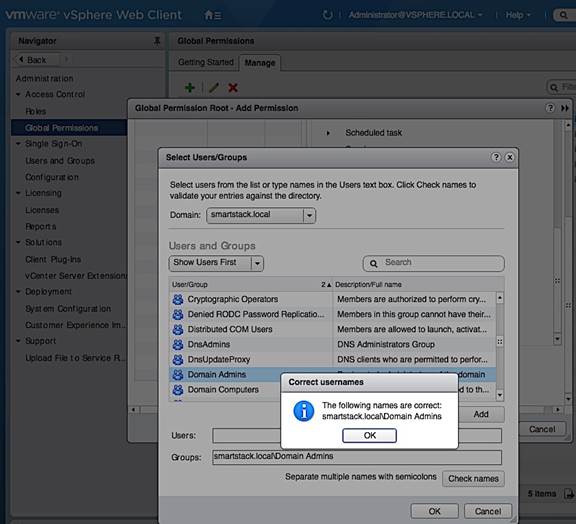
12. Verify that the added user/group is in the list.
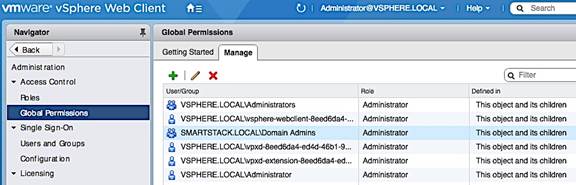
13. Navigate to Administration > Single Sign-on > Users and Groups > Users and verify. Select the AD domain to view the added group and users that can use AD authentication to access vCenter.
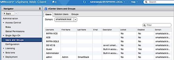
Setup VMware vCenter
Setup vCenter for Datacenter, Cluster, DRS and HA
1. Use a web browser to navigate to https://<vcenter-ip>. Click on vSphere Web Client(Flash) and login into vCenter.
2. Navigate to the Global Inventory Lists > Resources > vCenter Servers. Select vCenter instance (for example, 192.168.155.13). Go to Actions in the menu and select New Datacenter from the drop-down list.

3. In the New Datacenter pop-up window, specify a datacenter name and click OK.
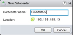
4. Navigate to Hosts and Clusters and select the newly created datacenter. Go to Actions in the menu and select New Cluster from the drop-down list.
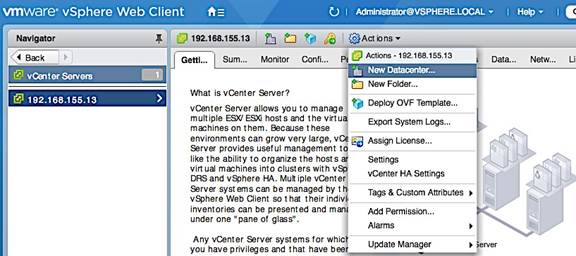
5. In the New Cluster window, provide a cluster name, enable DRS, vSphere HA and EVC. Click OK.
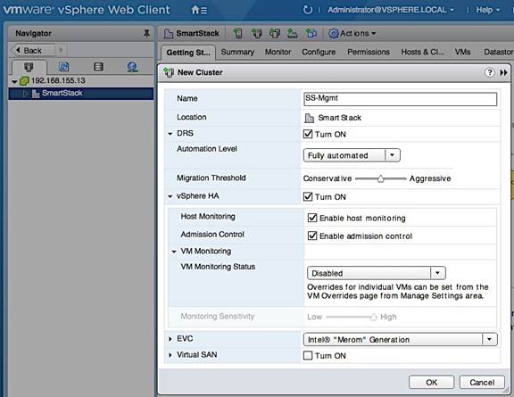
Specify Virtual Machine (VM) Swap File location – Cluster Level
1. From a browser, use vSphere web client to access vCenter. Navigate to Hosts and Clusters.
2. Select the newly created datacenter and cluster. Click on the Configure tab.
3. In the General section, click on the Edit button. In the Edit Cluster Settings pop-up window, select the radio button for Datastore specified by host.
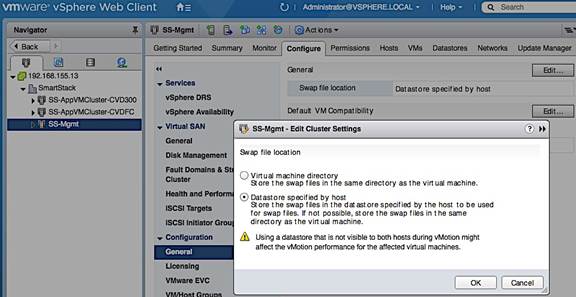
Enable ESXi Dump Collector
Follow the steps below to verify ESXi Dump Collector is running.
1. From a browser, use vSphere web client to access vCenter.
2. Navigate to Administration > System Configuration > Nodes and select the vCenter instance (192.168.115.13) from the list. Click the Related Objects tab.
3. Select VMware vSphere ESXi Dump Collector from the list of services running on the vCenter. Right-click to start the server and to specify the Startup Type.
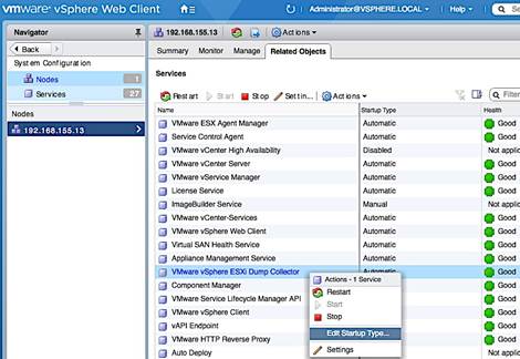
Deploy High Availability for vCenter
See Solution Deployment – Setup High Availabiltiy for vCenter section to configure vCenter HA. vCenter HA requires additional hosts, datastores and networking to be first setup. As such, deploying high availabilty for vCenter is covered after additional hosts have been deployed with the necessary datastores and networking.
Create vSphere Distributed Switch for Application VM Traffic
This design recommends using a separate distributed virtual switch (vDS) for Application VM traffic, separate from the virtual switches used for vMotion and Management traffic.
Workflow for vSphere Distributed Switch Configuration
Figure 19 Configuration Workflow for vSphere Distributed Switch
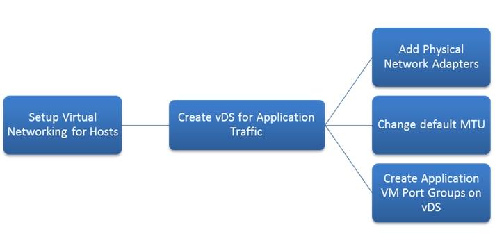
Create vSphere Distributed Switch
The distributed switch for Application VM traffic will use two uplinks (vNIC-A, vNIC-B). The traffic from these vNICs will take different paths across the fabric to provide redundancy and load balancing. To create and setup distributed virtual switch for Application VM traffic, complete the following steps.
1. From VMware vCenter using the vSphere web client, navigate to the appropriate datacenter. Right-click and select Distributed Switch > New Distributed Switch as shown below.
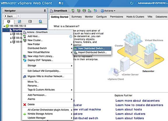
2. In the New Distributed Switch window, for Name and location, specify a name for the switch (for example, SS-vDS). Click Next.
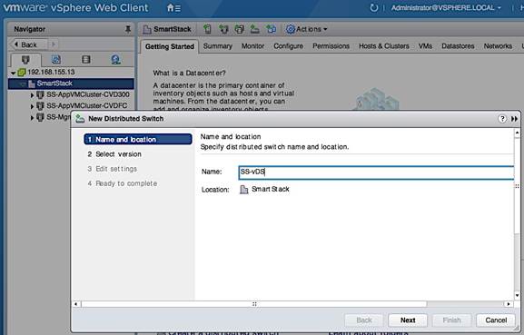
3. For Select version, select the distributed switch version to use. Click Next.
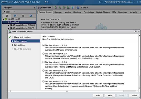
4. For Edit settings, specify the number of uplinks as ‘2’. Click Next.
5. Review settings and click Finish to complete.
Add Port Groups for Applications
To add port groups for Applications, complete the following configuration steps.
1. From VMware vCenter using the vSphere web client, navigate to Home > Networking. Select the newly created distributed switch (SS-vDS) in the datacenter. Right-click and select Distributed Port group > New Distributed Port Group.

2. In the New Distributed Port Group window, for Select name and location, specify a Name for the new Application VM port group (for example, APP1-PG). Click Next.
3. Under Configure settings, specify the VLAN type and ID. Use default settings for everything else. Click next.
4. Review settings. Click Finish to complete.
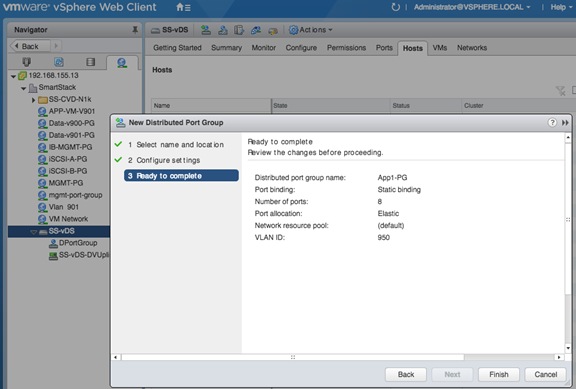
Edit Uplink Names
1. Select the distributed switch (SS-vDS) and right-click on Settings > Edit Settings…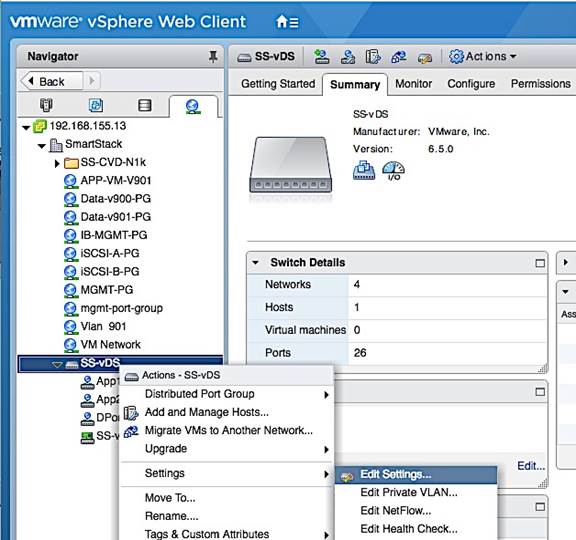
2. In the SS-vDS - Edit Settings window, click on Edit Uplink Names. In the Edit Uplink Names window, specify the new names. Click OK twice to complete.
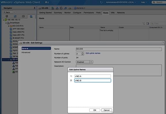
Solution Deployment – Add and Setup New Host with vCenter
This section covers the host level setup required once the ESXi install is complete and the host has come up using FC SAN boot. The configurations covered in this section are done through vCenter, using vSphere web client from a browser. The host level setup covered in this section are summarized below.
· Add Host to vCenter
· Enable NTP
· Update Host FNIC and ENIC drivers, if needed
· Install Nimble Connection manager (NCM)
· Verify Storage Configuration Post-NCM Install
· Setup ESXi Dump Collector – Host Side
· Register Nimble vCenter plugin
· Specify Virtual Machine (VM) Swap File Location
· Setup vSphere vSwitch Networking for Management and vMotion
· Add Host to vSphere Distributed Switch for Application VMs
· Extract Host Profile to use as a template deploying additional hosts
Add Host to vCenter
To add a new host to vCenter, follow the procedures outlined below.
1. From vSphere Web Client, login to vCenter and click on Hosts and Clusters from the home page.
2. Navigate to the datacenter and cluster to add the host to.
3. Right-click and select Add Host…
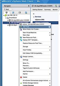
4. In the Add Host pop-up window, specify hostname/IP and location/cluster. Click Next.
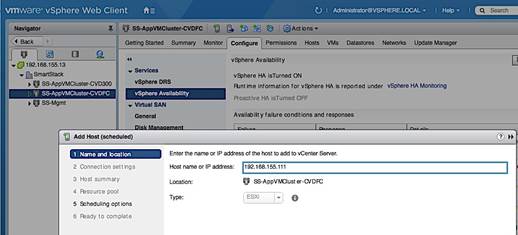
5. For connection settings, specify the root account and password. Click Next.
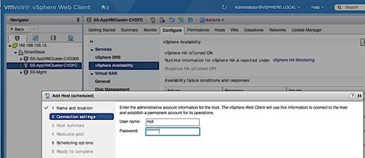
6. For Host Summary, review settings and click Next.
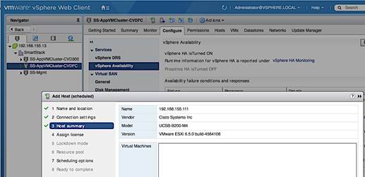
7. For Assign License, pick a license for the host to use. Click Next.
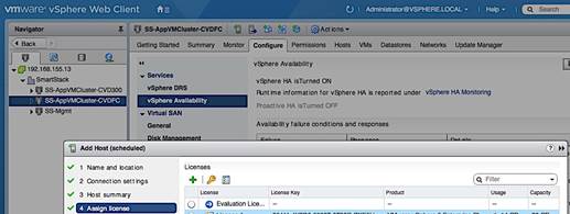
8. For Lockdown and Resource Pool, the default options were used.
9. For Scheduling Options, click on Change. In the Configure Scheduler window, specify when to run this action. Click Ok. Click Next.
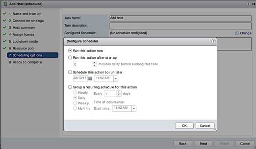
10. Review settings and click Finish to add host.
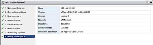
11. Verify the configuration of the newly added host from vCenter – see below. Note the image profile, HA state, networking, storage and other settings.
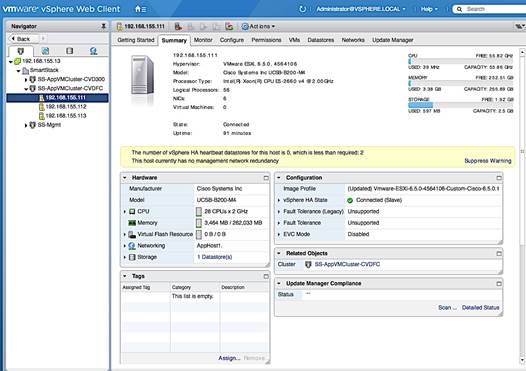
Enable NTP on Host
To enable NTP on the host from vCenter, complete the following steps.
1. From vSphere Web Client, login to vCenter and select the host in the inventory.
2. Click on the Configure tab and select System > Time Configuration and click on the Edit button.
3. In the Edit Time Configuration dialog box, select the radio button to Use Network Time protocol (Enable NTP Client).
4. For the NTP Service Startup Policy, select Start and Stop with the host.
5. For the NTP servers, specify the IP address of the server to use.
6. For the NTP Service Status, Click Start button to start the service.
7. Click OK to accept the NTP configuration.
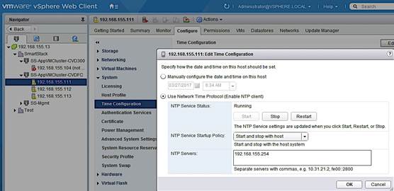
Update FNIC and ENIC Drivers on a ESXi Host
Once vCenter is up and running, VMware Update Manager (VUM) can be used to upgrade ESXi images, upgrade vendor specific drivers including Cisco FNIC and ENIC drivers, and other patches and extensions. As of vCenter VCSA 6.5, VUM is now integrated into vCenter. The procedures outlined in an earlier section can be used to individually update Cisco drivers on each host and would be necessary until vCenter is up and running. To update Cisco drivers with a Cisco ESXi image using the vCenter integrated VUM, follow the procedures outlined below.
1. From vSphere Web Client, login to vCenter and select the host in the inventory.
2. Select the Update Manager tab and click the Attach Baseline button.
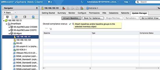
3. In the Attach Baseline or Baseline Group pop-up window for the host, select the Predefined Non-Critical and Critical Host Patches. Click OK.
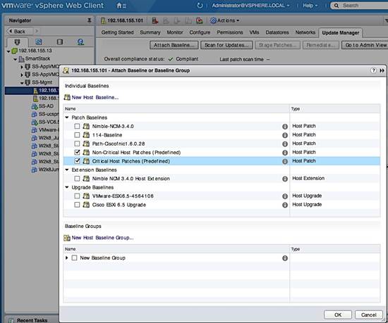
4. The two baselines show now be listed with a Compliance Status of Unknown initially and Non-Compliant if a scan was done recently.
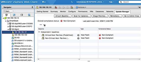
5. Click on Scan for Updates button to ensure you have the latest patches. In the Scan for Updates pop-up window for the host, leave everything selected and click OK.
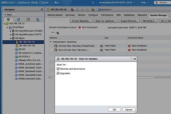
6. When the Scan Entity (see bottom of screen) Task completes, select the Non-Critical Patches Baseline to see a list of “Missing” non-critical patches that includes the Cisco ESXi image (highlighted). Cisco patches can also be imported individually by clicking on the Go to Admin View button > Patch Repository > Import Patches and selecting the patch .zip file.
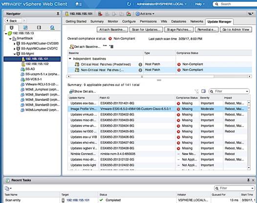
7. Click on the Remediate button to start applying the patch. In the Remediate pop-up dialog, in the select baselines screen, select non-critical patches. Click Next.
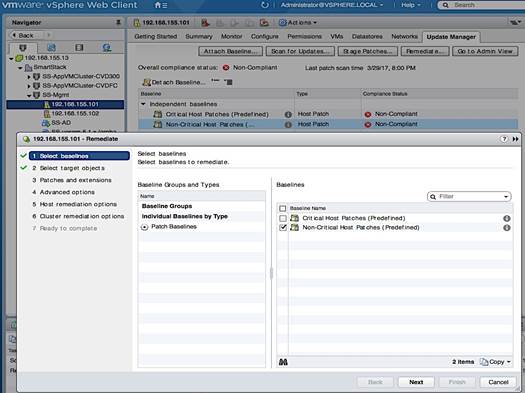
8. In the Select Target Objects screen, select the host. Click Next.
9. In the Patches and Extensions screen, click on the top checkbox to unselect all and then select the checkbox the Cisco ESXi image. Click Next.
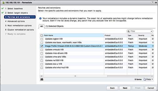
10. Click on the Select Objects tab to see the selection and additional details.
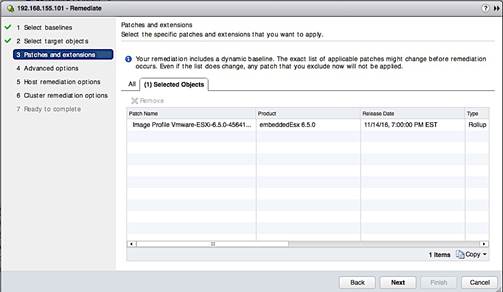
11. In the Advanced Options screen, select the settings for your environment.
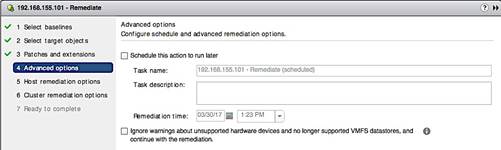
12. In the Host Remediation options screen, select settings for your environment.
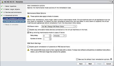
13. In the Cluster Remediation Options screen, select settings for your environment.
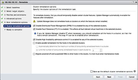
14. In the Ready to Complete screen, click on the pre-check remediate button and address any recommendations it provides. Review all the settings and click Finish to complete.
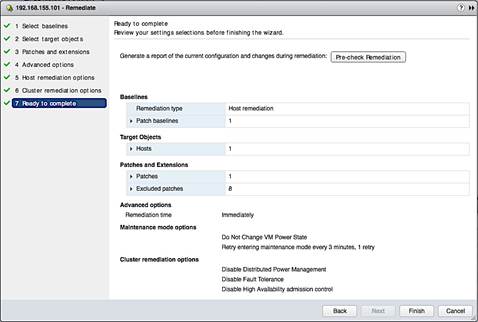
1. The host will be put in maintenance mode. For each patch, VUM will indicate if a reboot is required. If remediation fails attempting to put host in maintenance mode, cancel the task, put host in maintenance mode and try again.
2. The status of the remediation can be monitored by going to Monitor tab > Events or to the host console, if an upgrade is involved.
3. Once the task complete, SSH as root to the host and verify that the cisco patches installed matches the versions recommended by Cisco’s Hardware Compatibility List by executing the esxcli command: esxcli software vib list | grep CSCO.
Install Nimble Connection Manager (NCM)
NCM software is used to enable optimal configuration such as setting up multipathing correctly, queue depth, timeout values and so on. vSphere Update Manager (integrated into VCSA 6.5) should be able to reach Nimble’s Infosight website for this procedure.
1. Use vSphere Web Client from a browser to login to vCenter.
2. Click on the Home button and tab and select Update Manager.
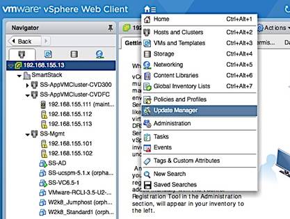
3. Select Servers > vCenter IP > Manage > Settings > Download Settings.
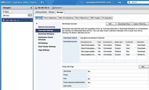
4. Click on the Edit button. In the Edit Download Sources window, click on + Add to specify the URL of the Nimble repository for NCM images as a download source. Click OK.
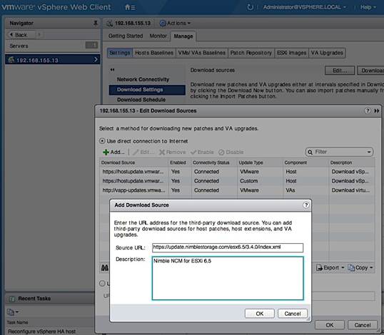
5. Click OK to see the list of downloaded sources. Nimble repository should now be on the list with a connectivity status of ‘Connected’.
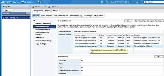
6. Click on Download Now button to initiate a patch download from all sources.
7. When the Download Patch Definitions task completes, navigate to Manage > Host Baselines and click on [+] New Baseline to add a new baseline for NCM software.
8. In the New Baseline window, specify a name, select type as extension. Click Next.
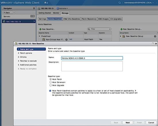
9. In the Extensions screen, search for Nimble to narrow the list. Select both extensions. For each item, scroll to the right to get patch IDs, impact (reboot), etc. Click Next.
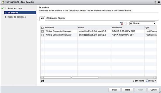
10. In the Ready to complete screen, review settings and click Finish. When this task is complete, click on Go to Compliance View button on the top right of the screen.
11. From compliance view screen, click on the Attach Baseline button. In the Attach Baseline window, go to Extension Baselines and select the newly added extension (Nimble-NCM-3.4.0-ESXi6.5). Click OK.
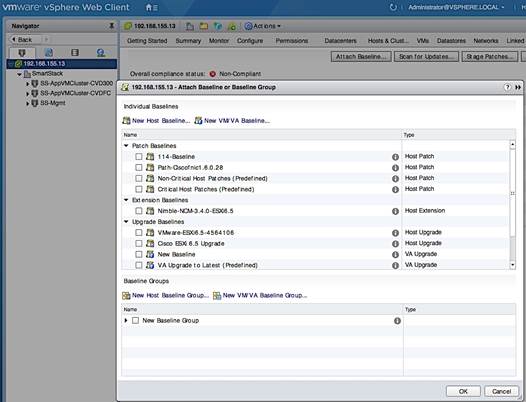
12. Click the Remediate button. In the Remediate pop-up window, select Host Remediation > Individual Baselines by Type > Extension Baselines. Select the checkbox for the NCM.
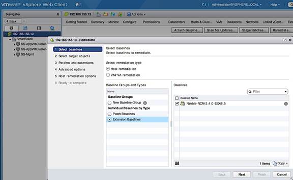
13. In the Select Target Objects screen, select the host(s) to upgrade. Click Next.
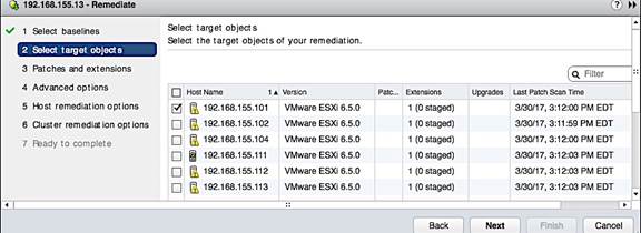
14. In the Patches and Extensions screen, select the checkbox for NCM. Click Next.
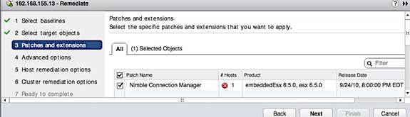
15. For the next 3 screens, select the settings for your environment.
16. In the Ready to Complete screen, review settings and click Finish.
17. If remediation fails attempting to put host in maintenance mode, cancel the task, put host in maintenance mode and then try again.
18. The status of the remediation can be monitored by navigating to the host > Monitor > Events or by going to the console of the host (if a reboot is involved).
19. Once the task complete, SSH to the host as root. Verify that the installed cisco patches are the versions recommended by Cisco’s Hardware Compatibility List on cisco.com by executing the esxcli command: esxcli software vib list | grep Nimble
![]()
20. Navigate back to the Host and click on Update Manager > Scan for Updates…the Host Extension baseline for NCM should now be in Compliant status.
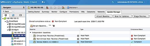
Verify Storage Configuration Post-NCM Install
In this section, the best practices implemented by installing NCM are verified.
1. Use vSphere web client to login to vCenter, select the Host under Hosts and Clusters. Click on the Manage tab and then Storage. Go to Storage devices in the menu and select one of the datastores.
2. In the bottom half of the window, click on the Properties tab and scroll down to the Multipathing Policies section and click Edit Multipathing. Select NIMBLE_PSP_DIRECTED from the drop-down list. Click OK.
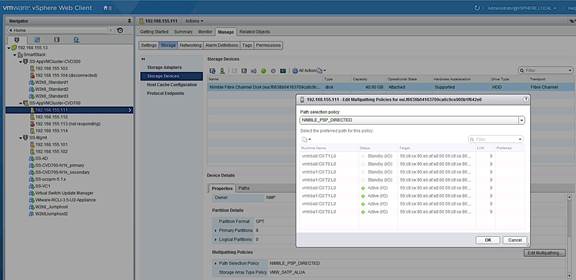
3. Click the Paths tab and verify that the info shows 4 Active Paths, 2 through Fabric A (vHBA0) and 2 through Fabric B (vHBA1). Similarly, there should also be 4 Standby Paths to the WWPN of Standby controller’s ports.
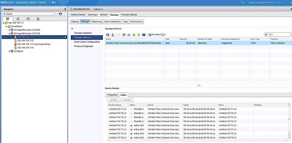
Register Nimble vCenter Plugin
To register the Nimble vCenter plugin, use a vCenter account that has sufficient privileges to install a plugin. You need to know the vCenter hostname or IP address. The plugin is part of the Nimble OS. Multiple plugins can be registered. To register the vCenter plugin, complete the following steps.
1. From the Nimble OS GUI main menu, select Administration > VMware Integration. Enter the vCenter server host name or IP address, user name, and password in the Add vCenter GUI.
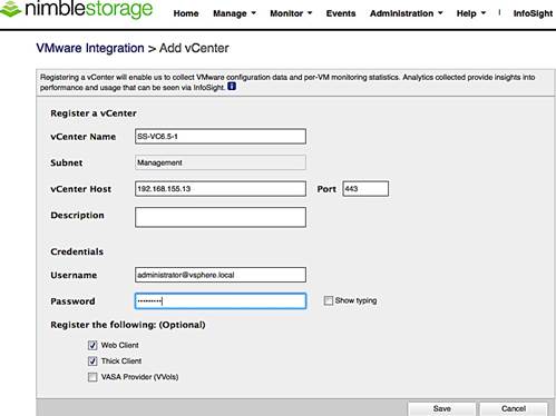
2. Click Save to accept changes and add vCenter
3. Click Test Status to ensure that the plugin has been registered.
4. Restart the vSphere thick client or re-login to the vCenter web client.
Verify Plugin Registration
A list of all registered plugins on the array can be discovered by doing the following:
1. Log into the Nimble OS CLI.
2. At the command prompt, enter the following command.
vmwplugin --list --username <username> --password <password> --server
<server_hostname-address> --port port_number <port number>
![]() If no port number is specified, port 443 is selected by default.
If no port number is specified, port 443 is selected by default.
3. The installed plugins are displayed as follows:
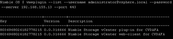
Specify Virtual Machine (VM) Swap File location – Host side
The recommendation for this design is to store the VM swap in a datastore created specifically to store the swap files. This requires a swap datastore to be created on the Nimble Array – see Storage section of this guide for creating a swap volume on the Nimble array. To change the virtual machine swap file location for a given host, configuration changes need to be done at the cluster and host level. The cluster level configuration changes the default location of storing the VM swap file in the same directory as the virtual machine to the datastore specified by the host. The host level configuration specifies the datastore (for example, SWAP_DS) for storing the VM swap file.
Complete the following configuration steps at the host level.
1. Using the vSphere web client from a browser, login to vCenter. Navigate to the datacenter and cluster to select the host.
2. On the right window pane, click on the Configure Tab. Select Virtual Machines > Swap file location. Click the Edit button on the right side to edit the swap file location.
3. In the Edit Swap File Location pop-up window, select the datastore. Click OK.
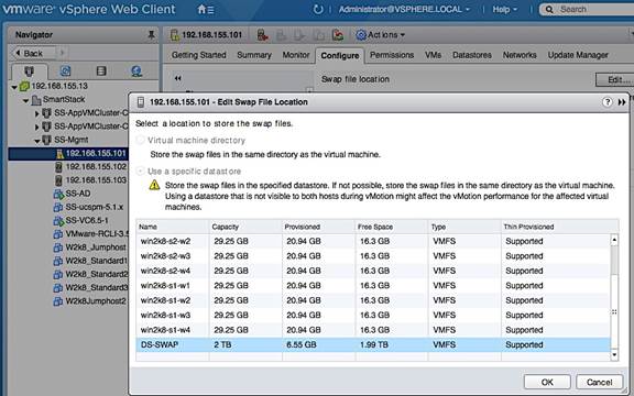
Setup ESXi Dump Collector - Host side
The host side configuration for ESXi Dump collector is done through CLI on the first host and then using a host profile for the remaining hosts. It is not necessary to use host profiles but host profiles enforce consistency, prevent user errors and easier than individually configuring each host.
Configure ESXi Dump Collector using ESX Shell/CLI
A core dump during a host failure is typically sent to the local disk. The following commands enable hosts to send the core dump to an external network server. In this setup, core dumps are sent to the vCenter.
1. SSH into the host using root account and password.
2. Execute the following commands to enable coredump to Dump Collector.
— esxcli system coredump network set --interface-name vmk0 --server-ip 192.168.155.13 --server-port 6500
— esxcli system coredump network set --enable true
— esxcli system coredump network check
— /sbin/auto-backup.sh (to save configuration so it persists after a reboot)
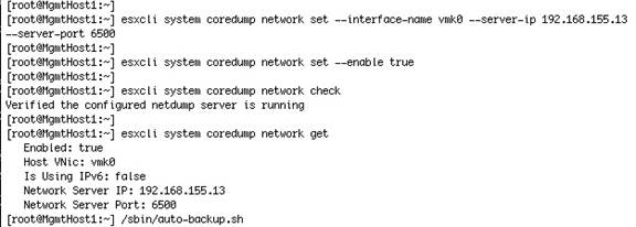
3. See Generating Host Profile Section for generating a host profile that can then be edited using the steps outlined below.
Configure ESXi Dump Collector using a Host Profile
To use host profiles for configuring additional hosts, follow the steps below to use this host as a template.
1. Using vSphere web client from a browser, login to vCenter.
2. From Home page, click-on Policies and Profiles, select Host Profiles.
3. Right-click on the host profile to use as a template for configuring Dump Collector settings and select Edit Settings.
4. On the Edit Host Profile section of the dialogue, select Network Configuration > Network Coredump Settings.
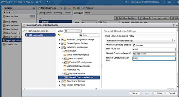
5. Select Enabled check box. Specify the host NIC, server IP and server port. Click Finish.
6. Configure additional hosts by attaching and remediating this host profile.
Setup vSphere vSwitch Networking on Host for Management and vMotion
This section covers the virtual switch (vSwitch) setup to enable network connectivity to hosts and VMs running on the hosts. The configuration workflow is as shown in the figure below.
Workflow for vSphere vSwitch Networking Setup
Figure 20 vSwitch Networking Setup Workflow
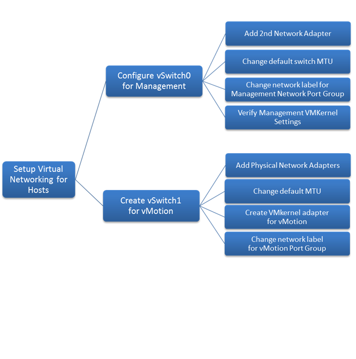
Configure vSwitch0 for Management
This design recommends using a separate vSwitch for management using two uplink vNICs (MGMT-A, MGMT-B). Traffic from these vNICs traverse in different paths across fabric providing redundancy and load balancing.
Add Physical Network Adapters to vSwitch
The vNICs appear as vmnics to ESXi but only one vmnic is associated with the default virtual switch (vSwitch0) on the host. To add the second vNIC to vSwitch0, complete the following configuration steps for each host in the cluster.
1. From VMware vCenter using the vSphere web client, navigate to the datacenter and cluster where the host resides.
2. Select the host (for example, 192.168.155.111). On the right window pane, click on the Configure Tab. Click on Networking > Virtual switches and select vSwitch0 from the Virtual Switches section. Click on the Manage physical adapter’s icon (3rd icon) to open the Manage Physical Network Adapters for vSwitch0 window.
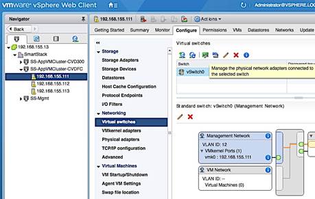
3. Click [+] to add second Adapter. Select vmnic1 in the Add Physical Adapters to the Switch window and click OK twice to add vmnic1 as an Active adapter to vSwitch0.
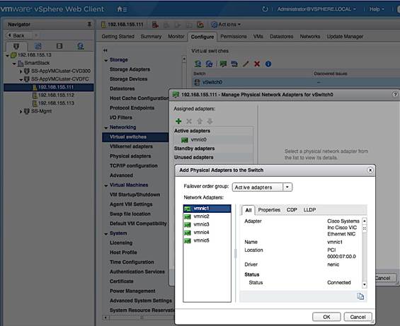
4. The resulting configuration is shown below. Note that both vmnics are deployed in Active/Active state – see Edit Settings from vSwitch0 level for default load balancing and failover configuration.
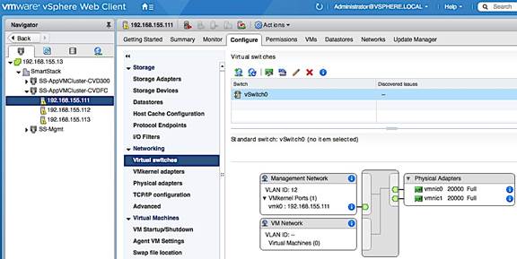
Change the Default MTU of the vSwitch
This design generally recommends an end-to-end MTU of 9000 including management vSwitch so that a reboot of the host is not necessary if an MTU change is needed in the future. To change the default MTU, complete the following steps for each host in the cluster.
1. From VMware vCenter using the vSphere web client, navigate to the datacenter and cluster where the host resides.
2. Select the host. On the right window pane, click on the Configure Tab. Click on Networking > Virtual switches and select vSwitch0 from the Virtual Switches section. Click on the Edit Settings icon (5th icon) to open the Edit settings window. Change the MTU to 9000 as shown below. Click OK to accept the edits and close the window.
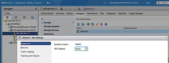
Change Management Port Group Settings
To align with the naming scheme used in the design, the network label for the Management port group was changed. For each host in the cluster, complete the following configuration steps to change the network label for the Management port group.
1. From VMware vCenter using the vSphere web client, navigate to the datacenter and cluster where the host resides.
2. Select the host. On the right window pane, select the Configure Tab. Click on Networking > Virtual switches and select vSwitch0 from the Virtual Switches section. In the Standard Switch: vSwitch0 section of the window, select the Management Network and click on the Edit Settings icon.
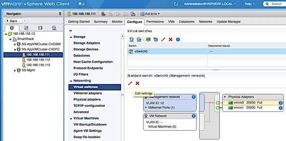
3. In the Management Network: Edit Settings pop-up window, select Properties and change the network label and VLAN ID to reflect the naming scheme and VLAN ID used in the design.
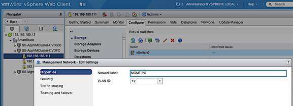
4. In the Management Network: Edit Settings pop-up window, select Teaming and failover and verify the load balancing and failover settings for the management port group. The management port group, by default, is enabled for ‘Override’ and typically uses a different setting from the default vSwitch settings. In vSphere 6.5, the newly added vmnic1 shows up under ‘Unused adapters’ as shown below.
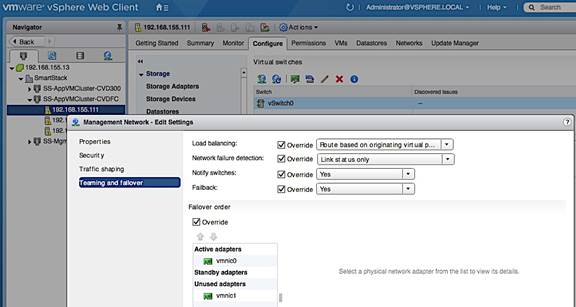
5. To provide redundancy for management traffic, use the Up Arrow keys to move the second vmnic to the ‘Standby Adapters’ list to provide Active/Passive redundancy. Alternatively, uncheck ‘Override’ to use vSwitch level settings for Teaming and failover.
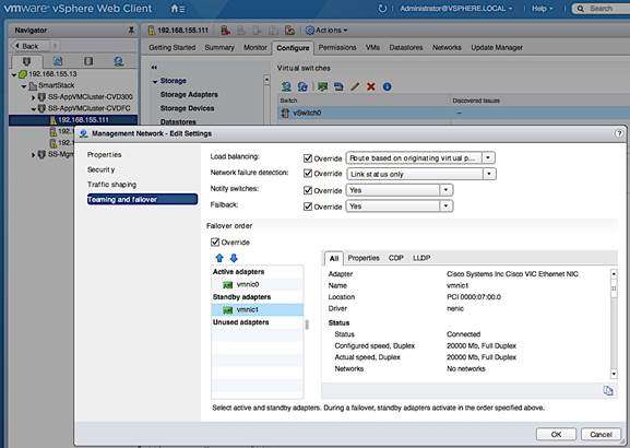
6. Click OK to accept the edits and close the window.
Verify Management VMkernel adapter settings
1. In the Standard Switch: vSwitch0 section of the window, select vmk0 in the Management port group and click on the Edit Settings icon. 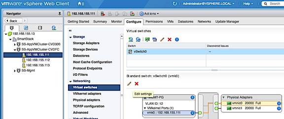
2. In the vmk0 – Edit Settings window, for Port properties, verify that Management Traffic is checked in the Enable services section.
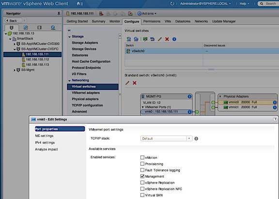
3. Click OK to close the window.
Create vSwitch1 for vMotion
This design recommends using a separate vSwitch for vMotion with two uplink vNICs (vMotion-A, vMotion-B). Traffic from these vNICs will use different paths across the fabric to provide redundancy and load balancing. To create and setup vSwitch1 for vMotion, complete the following steps.
1. From VMware vCenter using the vSphere web client, navigate to the and cluster where the host resides. Select the host.
2. On the right window pane, select the Configure Tab. Click on Networking > Virtual Switches. Click on the Add host networking icon (1st icon).
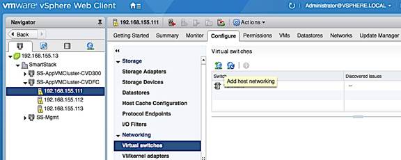
3. In the Add Networking window, select connection type as VMkernel Network Adapter. Click Next.
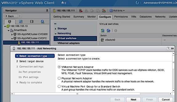
4. Select target device as New standard switch as shown below. Click Next to continue.
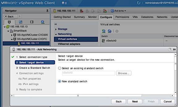
5. Under Create a Standard Switch, specify the network adaptors to use for vSwitch1.
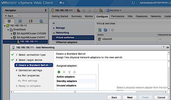
6. Click [+] to add two add two vNICs to vSwitch1 for redundancy and click OK to add.
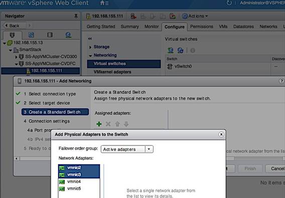
7. Click Next to continue.
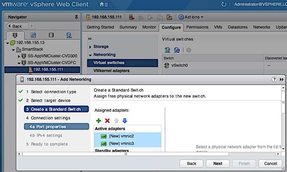
8. Under Connection Settings, for the Port Properties, specify the Network Label for vMotion vmk and port group, vMotion VLAN ID (Optional) and enable vMotion traffic in the Enable Services section. Click Next to continue.
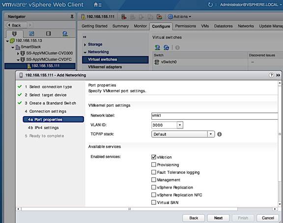
9. For IPv4 Settings under Connection Settings, specify the IPv4 address to be used by vMotion VMkernel adapter. Click Next to continue.
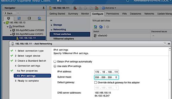
10. Review and click Finish to create vSwitch1.
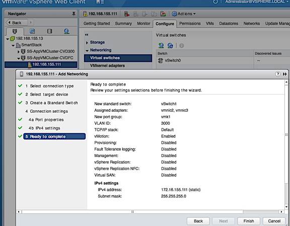
11. Verify vSwitch1 setup.
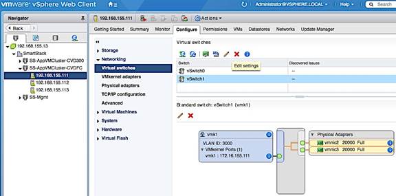
Change/Verify vSwitch1 Settings
For higher performance, the design uses an end-to-end MTU of 9000 for vMotion traffic. To change the default MTU, complete the following steps.
1. From VMware vCenter using the vSphere web client, navigate to the datacenter and cluster where the host resides.
2. Select the host. On the right window pane, select the Configure Tab. Select Networking > Virtual switches. From the list of Virtual Switches, select vSwitch1. Click the Edit Settings icon (5th icon) to open the Edit settings window.
3. Change MTU to 9000 as shown below. Click OK to accept the change.
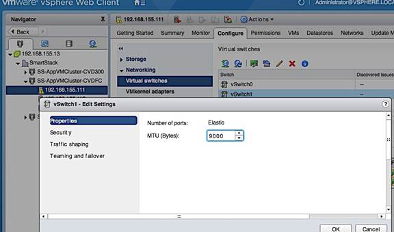
4. Verify Teaming and Failover settings is as follows for vSwitch1.
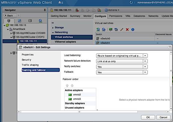
Change/Verify vMotion Port Group Settings
1. Change network label for vMotion port group. In the Standard Switch: vSwitch1 section of the window, select vmk1 port group and click on the Edit Settings icon.

2. In the vmk1 – Edit Settings window, under Properties, change Network label as shown below.
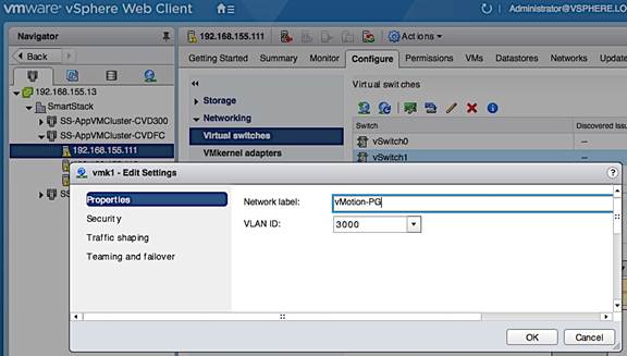
3. Verify vMotion Port Group level settings for NIC Teaming and failover.
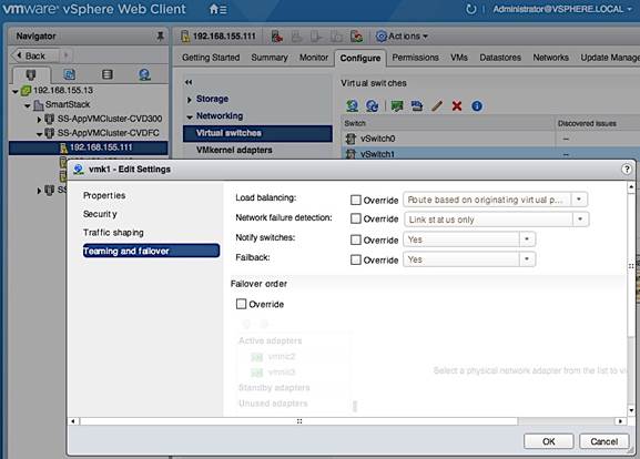
4. Verify vSwitch1 setup is as follows.
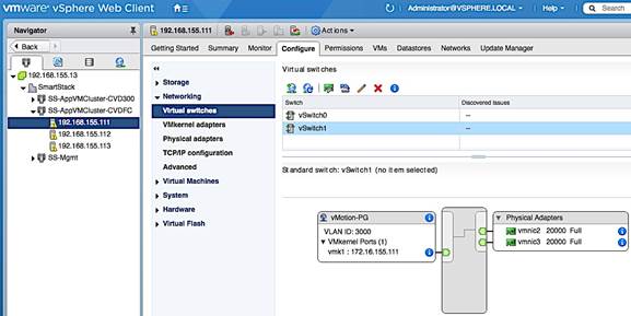
Change/Verify vMotion VMkernel Adapter MTU
1. In the Standard Switch: vSwitch1 section of the window, select vMotion-PG port group and then vmk1. Click on the Edit Settings icon(3rd icon).
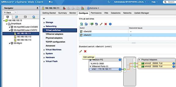
2. In the Edit Settings window for vmk1, select NIC settings and change the MTU to 9000. Click OK to accept the edits and close the window.
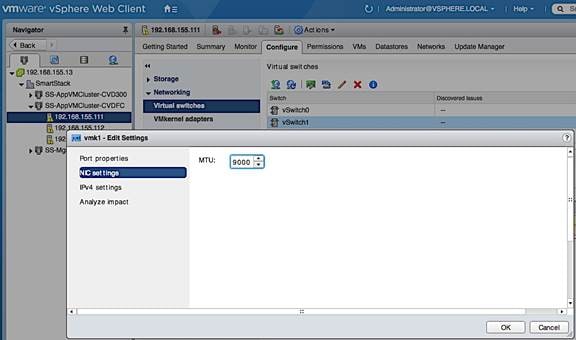
Add Host to vSphere Distributed Switch for Application VMs
1. Select the distributed switch (SS-vDS) and right-click on Add and Manage Hosts… 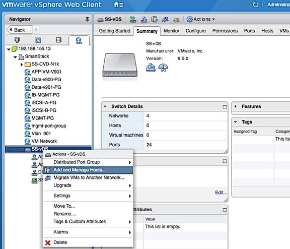
2. In the Add and Manage Hosts, under Select task, click on the Add Hosts radio button. Click Next.
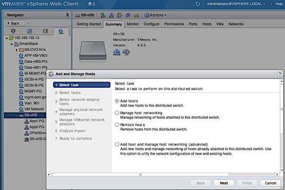
3. For Select hosts, click [+] New Hosts… to add new host.
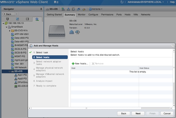
4. In the Select new hosts window, select the host to be added. Click OK.
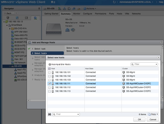
5. Click Next to continue.
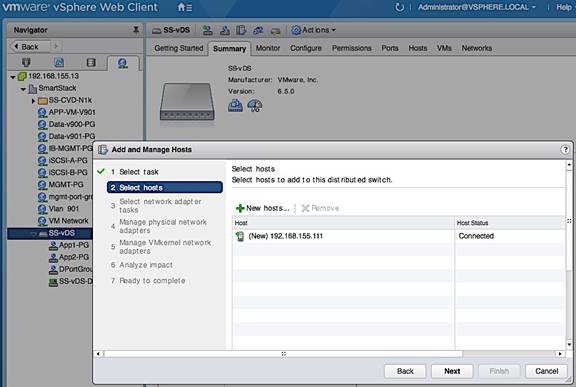
6. For Select network adapter tasks, select Manage physical adapters option. Click Next.
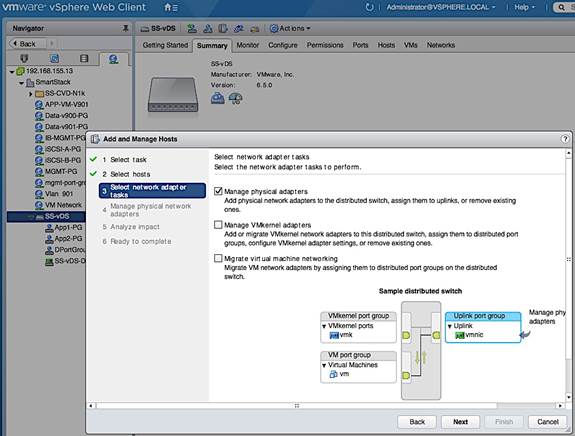
7. For Manage physical network adapters, select the first vmnic to be added and click on Assign uplink icon.
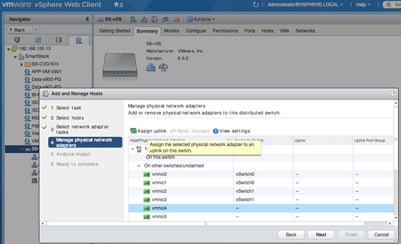
8. In the Select an Uplink for vmnic pop-up window, specify the uplink name for the new vmnic. Click OK.
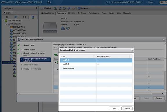
9. Repeat the above steps for the second vmnic. Click Next.
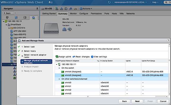
10. For Analyze Impact, click Next to accept default options.
11. Review setting and click Finish to complete.
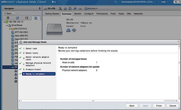
12. Review the distributed switch networking setup on the host.
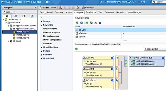
Extract Host Profile to use as a template deploying additional hosts
Host Profiles can be used to take the configuration from one template host and applying it to a large group of hosts. Once the template host is setup, the configuration is extracted into a host profile. This host profile can be deployed on the next host with some host specific customization (mainly IP addressing). This setup uses host profiles to quickly roll out new hosts and to ensure consistency in host configurations. Use the following procedure to extract host profiles, customize it and apply the template host profile to configure new hosts.
Extract Host Profile from Template Host
1. Use vSphere web client from a browser to login to vCenter. Navigate to Hosts and Clusters > Datacenter > Cluster and select the host to use as a template for generating a host profile.
2. Right-click and select Host Profiles > Extract Host Profile…
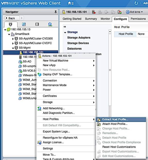
3. In the Extract Host Profile pop-up window, specify a name. Click Next.
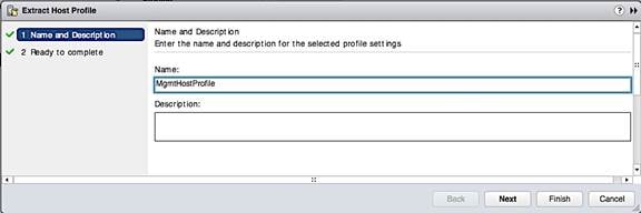
4. Review the settings and click Finish to extract the Host Profile.
5. To view all the settings included in this host profile, navigate to Home > Policies and Profiles > Host Profiles and select the newly created host profile from the list. Right-click and select Edit Settings.
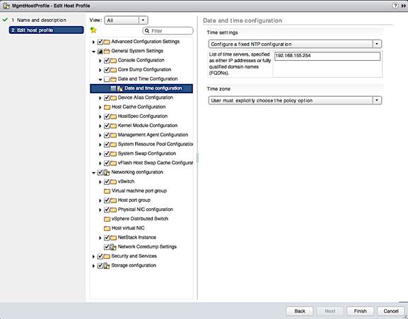
Apply Host Profile to setup New Host
1. Use vSphere web client from a browser to login to vCenter. Navigate to Home > Policies and Profiles > Host Profiles and select the newly created host profile from the list.
2. Right-click and select Attach/Detach Hosts and Clusters…
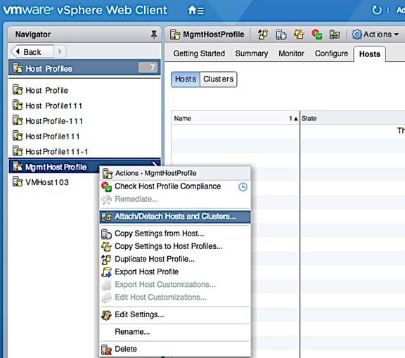
3. In the Attach/Detach Hosts and Clusters pop-up window, select the host or cluster to attach the host profile to. Click on the Attach button. Click Next.
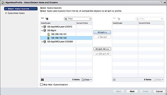
4. In the Customize Hosts screen, specify the host specific configuration for the Required fields. Click Finish.
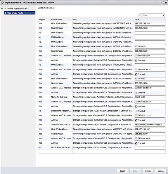
5. Select the above host and click on Enter Maintenance button at the top. This is not necessary and the remediate step that follows would do this but this step could avoid issues with putting host in Maintenance mode during Remediate.
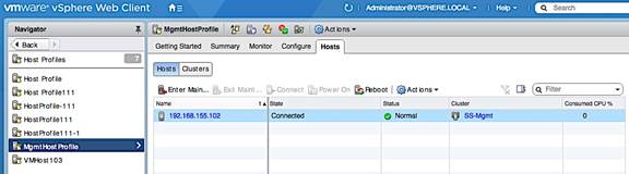
6. Right-click on the host profile and select Remediate.
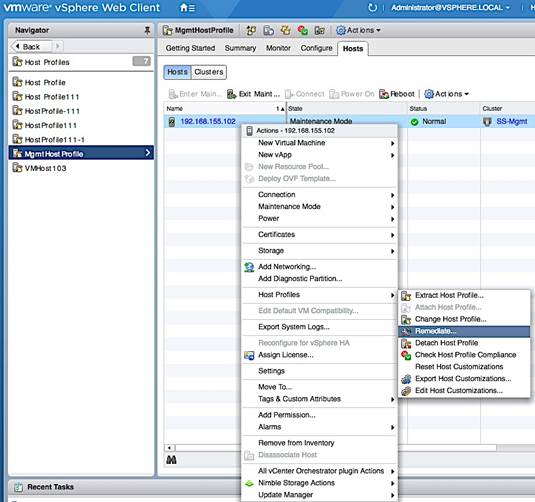
7. In the Remediate Hosts based on Host Profile window, select the host, review settings and click Finish. Review changes to the host once the remediation process completes.
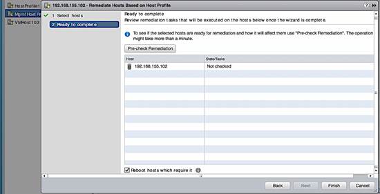
8. Exit Maintenance Mode and host is now ready for use.
Before enabling vCenter HA, review the requirements for vSphere HA outlined in the VMware vSphere 6.5 documentation. vCenter HA requires 2-3 servers with separate datastores and HA network (vlan, IP, port-group) for vCenter HA. The next section covers the pre-setup specific to vCenter HA.
Add vCenter HA Vlan to Cisco UCS Fabric
vCenter HA requires a dedicated HA network. The Vlan for this dedicated network needs to be added to the UCS fabric to enable communication between redundant vCenter instances hosted on different UCS servers in the Management UCS cluster. This network is separate from the management network. To add vCenter HA Vlan to the UCS FI hosting the vCenter VMs, follow the steps outlined below.
1. Login to UCS Fabric Interconnect using a web browser.
2. Click on the LAN icon in the left navigation pane.
3. Navigate to LAN > LAN Cloud > VLANs. Right-click and select Create Vlans.
4. In the Create VLANs window, specify a name and vlan id for the vCenter HA network. Click OK.
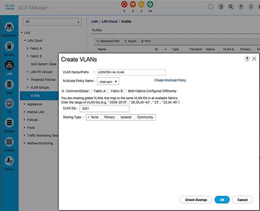
5. Click OK again to add the vlan to the uplink ports of the UCS servers.
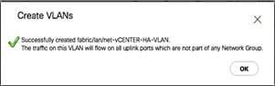
Create vCenter HA network
To create a dedicated vCenter HA network, a port group needs to be created for vCenter HA Vlan in order to enable communication between redundant vCenter instances hosted on different UCS servers. A dedicated vSwitch could be created for this but the existing Management vSwitch was used in this setup. To create a vCenter HA port group on Management vSwitch, follow the steps outlined below.
1. From vSphere web client, select the first UCS server (192.168.155.101) hosting the vCenter VM.
2. Click on the Configure Tab. Select Networking > Virtual Switches > vSwitch0. Click on the Add Host Networking (1st) icon above the list of virtual switches.
3. In the Add Networking window, for Select Connection type, select the radio button for Virtual Machine Port Group.
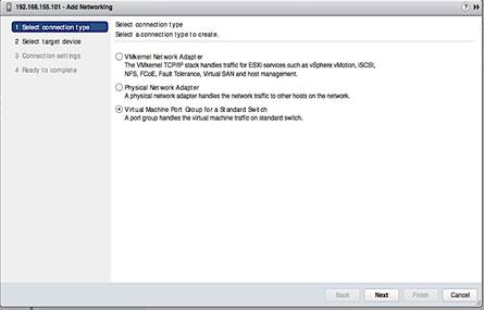
4. In the Add Networking window, for Select Target device, select the radio button for Select an existing standard switch (vSwitch0). Click Next.
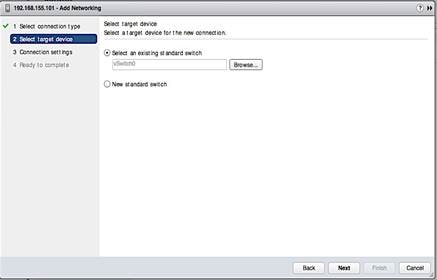
5. In the Connection Settings screen, specify a name for the port group and vlan. Click Next.
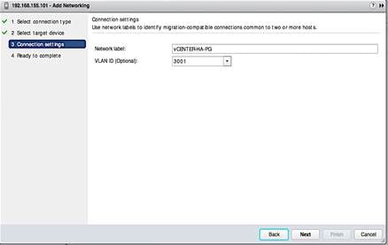
6. Review the settings and click Finish to complete.
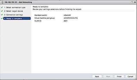
7. Repeat above steps on the UCS servers hosting Passive and Witness vCenter instances.
Configure vCenter HA
To configure vCenter HA, follow the steps outlined below.
1. From vSphere web client, click on the Configure tab and select Settings > vCenter HA and click on the Configure button on the top right side of the window.
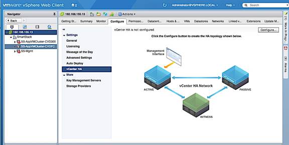
2. In the Configure vCenter HA pop-up window, select Basic for the configuration option.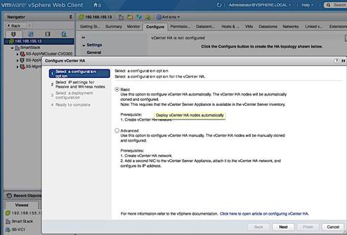
3. In the Add a vCenter HA network adapter for Active node screen, specify the IP address, Subnet Mask of the Active node and the Port Group for vCenter HA network created earlier. Click Next.
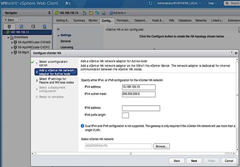
4. In the Select IP settings for Passive and Witness nodes screen, click on the Advanced button next to Passive node. Specify the IP settings for the Passive Node. Click OK.
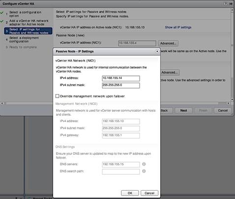
5. On the same screen, click on the Advanced button next to Witness Node. Specify the IP settings for Witness node. Click OK. Click Next.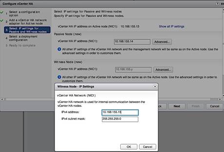
6. On the Select a Deployment Configuration screen, click on the Compatibility Warnings… for each node. Review the compatibility issues.
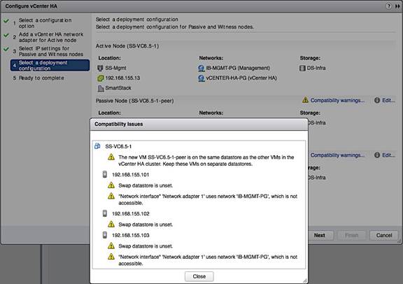
7. On the same screen, for each Node, click on the Edit icon to address the issues until the Compatibility Checks succeed. Exit the HA setup if needed to fix the issues.
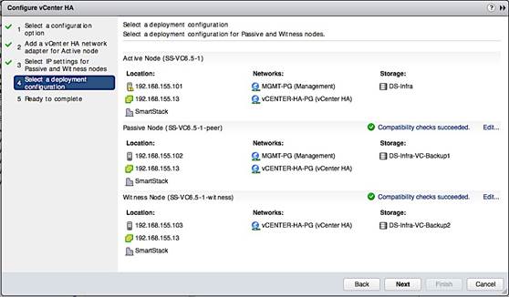
![]() When using the Edit option above to select a datastore for each vCenter instance, click on the Advanced button at the bottom of datastore selection screen to select the same for the associated disks as well.
When using the Edit option above to select a datastore for each vCenter instance, click on the Advanced button at the bottom of datastore selection screen to select the same for the associated disks as well.
8. Review settings and click Finish to complete the setup.
Cisco Nexus A Configuration
!Command: show running-config
!Time: Thu Mar 23 09:49:36 2017
version 7.0(3)I2(4)
switchname D01-n9k1
vdc D01-n9k1 id 1
limit-resource vlan minimum 16 maximum 4094
limit-resource vrf minimum 2 maximum 4096
limit-resource port-channel minimum 0 maximum 511
limit-resource u4route-mem minimum 248 maximum 248
limit-resource u6route-mem minimum 96 maximum 96
limit-resource m4route-mem minimum 58 maximum 58
limit-resource m6route-mem minimum 8 maximum 8
feature nxapi
cfs eth distribute
feature udld
feature interface-vlan
feature lacp
feature vpc
username admin password 5 $1$yjwMRDJV$ixhesPxYkTFiEPlkzje6F/ role network-admin
ip domain-lookup
system default switchport shutdown
copp profile strict
snmp-server user admin network-admin auth md5 0xa86138602a80f77232959a8e92306867 priv 0xa86138602a80f77232959a8e92306867 localizedkey
rmon event 1 log trap public description FATAL(1) owner PMON@FATAL
rmon event 2 log trap public description CRITICAL(2) owner PMON@CRITICAL
rmon event 3 log trap public description ERROR(3) owner PMON@ERROR
rmon event 4 log trap public description WARNING(4) owner PMON@WARNING
rmon event 5 log trap public description INFORMATION(5) owner PMON@INFO
snmp-server community public group network-admin
ntp server 192.168.155.254 use-vrf management
vlan 1-2,12,900-901,950-951,3000
vlan 2
name Native-VLAN
vlan 12
name IB-MGMT
vlan 900
name VM-Traffic-VLAN900
vlan 901
name VM-Traffic-VLAN901
vlan 950
name APP1
vlan 951
name APP2
vlan 3000
name vMotion
spanning-tree port type edge bpduguard default
spanning-tree port type edge bpdufilter default
vrf context management
ip route 0.0.0.0/0 192.168.155.1
port-channel load-balance src-dst ip-l4port-vlan
vpc domain 155
peer-switch
role priority 10
peer-keepalive destination 192.168.155.4 source 192.168.155.3
peer-gateway
auto-recovery
ip arp synchronize
interface Vlan1
interface port-channel11
description D01-Mini1-A
switchport mode trunk
switchport trunk allowed vlan 12,900-901
spanning-tree port type edge trunk
vpc 11
interface port-channel12
description D01-Mini1-B
switchport mode trunk
switchport trunk allowed vlan 12,900-901
spanning-tree port type edge trunk
vpc 12
interface port-channel13
description D01-FI-A
switchport mode trunk
switchport trunk native vlan 2
switchport trunk allowed vlan 12,950-951,3000
spanning-tree port type edge trunk
spanning-tree guard root
mtu 9216
no lacp graceful-convergence
vpc 13
interface port-channel14
description D01-FI-B
switchport mode trunk
switchport trunk native vlan 2
switchport trunk allowed vlan 12,950-951,3000
spanning-tree port type edge trunk
spanning-tree guard root
mtu 9216
no lacp graceful-convergence
vpc 14
interface port-channel155
description vPC peer-link
switchport mode trunk
switchport trunk native vlan 2
switchport trunk allowed vlan 12,900-901,950-951,3000
spanning-tree port type network
vpc peer-link
interface Ethernet1/1
no shutdown
interface Ethernet1/2
no shutdown
interface Ethernet1/3
no shutdown
interface Ethernet1/4
no shutdown
interface Ethernet1/5
no shutdown
interface Ethernet1/6
no shutdown
interface Ethernet1/7
no shutdown
interface Ethernet1/8
no shutdown
interface Ethernet1/9
no shutdown
interface Ethernet1/10
no shutdown
interface Ethernet1/11
no shutdown
interface Ethernet1/12
no shutdown
interface Ethernet1/13
description ** D01-mini1-a:p1 **
switchport mode trunk
switchport trunk allowed vlan 12,900-901
channel-group 11 mode active
no shutdown
interface Ethernet1/14
description ** D01-mini1-b:p1 **
switchport mode trunk
switchport trunk allowed vlan 12,900-901
channel-group 12 mode active
no shutdown
interface Ethernet1/15
no shutdown
interface Ethernet1/16
no shutdown
interface Ethernet1/17
switchport access vlan 12
no shutdown
interface Ethernet1/18
no shutdown
interface Ethernet1/19
no shutdown
interface Ethernet1/20
no shutdown
interface Ethernet1/21
no shutdown
interface Ethernet1/22
no shutdown
interface Ethernet1/23
description ** D01-FI-A:p15 **
switchport mode trunk
switchport trunk native vlan 2
switchport trunk allowed vlan 12,950-951,3000
mtu 9216
udld enable
channel-group 13 mode active
no shutdown
interface Ethernet1/24
description ** D01-FI-B:p15 **
switchport mode trunk
switchport trunk native vlan 2
switchport trunk allowed vlan 12,950-951,3000
mtu 9216
udld enable
channel-group 14 mode active
no shutdown
interface Ethernet1/25
no shutdown
interface Ethernet1/26
no shutdown
interface Ethernet1/27
no shutdown
interface Ethernet1/28
no shutdown
interface Ethernet1/29
no shutdown
interface Ethernet1/30
no shutdown
interface Ethernet1/31
no shutdown
interface Ethernet1/32
no shutdown
interface Ethernet1/33
no shutdown
interface Ethernet1/34
no shutdown
interface Ethernet1/35
no shutdown
interface Ethernet1/36
no shutdown
interface Ethernet1/37
no shutdown
interface Ethernet1/38
no shutdown
interface Ethernet1/39
no shutdown
interface Ethernet1/40
no shutdown
interface Ethernet1/41
no shutdown
interface Ethernet1/42
no shutdown
interface Ethernet1/43
no shutdown
interface Ethernet1/44
no shutdown
interface Ethernet1/45
no shutdown
interface Ethernet1/46
no shutdown
interface Ethernet1/47
no shutdown
interface Ethernet1/48
description Mgmt via N55k-FEX
switchport access vlan 12
spanning-tree port type edge
spanning-tree bpdufilter enable
no shutdown
interface Ethernet1/49
no shutdown
interface Ethernet1/50
no shutdown
interface Ethernet1/51
no shutdown
interface Ethernet1/52
no shutdown
interface Ethernet1/53
description D01-n9k2:e1/53
switchport mode trunk
switchport trunk native vlan 2
switchport trunk allowed vlan 12,900-901,950-951,3000
udld enable
channel-group 155 mode active
no shutdown
interface Ethernet1/54
description D01-n9k2:e1/54
switchport mode trunk
switchport trunk native vlan 2
switchport trunk allowed vlan 12,900-901,950-951,3000
udld enable
channel-group 155 mode active
no shutdown
interface mgmt0
vrf member management
ip address 192.168.155.3/24
clock timezone EST -5 0
line console
line vty
session-limit 16
boot nxos bootflash:/nxos.7.0.3.I2.4.bin
Nexus 9000 B Configuration
!Command: show running-config
!Time: Thu Mar 23 10:07:57 2017
version 7.0(3)I2(4)
hostname D01-n9k2
vdc D01-n9k2 id 1
limit-resource vlan minimum 16 maximum 4094
limit-resource vrf minimum 2 maximum 4096
limit-resource port-channel minimum 0 maximum 511
limit-resource u4route-mem minimum 248 maximum 248
limit-resource u6route-mem minimum 96 maximum 96
limit-resource m4route-mem minimum 58 maximum 58
limit-resource m6route-mem minimum 8 maximum 8
feature nxapi
cfs eth distribute
feature udld
feature interface-vlan
feature lacp
feature vpc
username admin password 5 $1$aEaZHhoQ$CFqgw6s/wCr8c8Kzb.1DV1 role network-admin
ip domain-lookup
copp profile strict
snmp-server user admin network-admin auth md5 0x5469a3fe245f27f90497c0657c9225fe priv 0x5469a3fe245f27f90497c0657c9225fe localizedkey
rmon event 1 log trap public description FATAL(1) owner PMON@FATAL
rmon event 2 log trap public description CRITICAL(2) owner PMON@CRITICAL
rmon event 3 log trap public description ERROR(3) owner PMON@ERROR
rmon event 4 log trap public description WARNING(4) owner PMON@WARNING
rmon event 5 log trap public description INFORMATION(5) owner PMON@INFO
snmp-server community public group network-admin
ntp server 192.168.155.254 use-vrf management
vlan 1-2,12,900-901,950-951,3000
vlan 2
name Native-VLAN
vlan 12
name IB-MGMT
vlan 900
name VM-Traffic-VLAN900
vlan 901
name VM-Traffic-VLAN901
vlan 950
name APP1
vlan 951
name APP2
vlan 3000
name vMotion
spanning-tree port type edge bpduguard default
spanning-tree port type edge bpdufilter default
vrf context management
ip route 0.0.0.0/0 192.168.155.1
port-channel load-balance src-dst ip-l4port-vlan
vpc domain 155
peer-switch
role priority 20
peer-keepalive destination 192.168.155.3 source 192.168.155.4
peer-gateway
auto-recovery
ip arp synchronize
interface Vlan1
interface port-channel11
description D01-Mini1-A
switchport mode trunk
switchport trunk allowed vlan 12,900-901
spanning-tree port type edge trunk
vpc 11
interface port-channel12
switchport mode trunk
switchport trunk allowed vlan 12,900-901
spanning-tree port type edge trunk
vpc 12
interface port-channel13
description D01-FI-A
switchport mode trunk
switchport trunk native vlan 2
switchport trunk allowed vlan 12,950-951,3000
spanning-tree port type edge trunk
spanning-tree guard root
mtu 9216
no lacp graceful-convergence
vpc 13
interface port-channel14
description D01-FI-B
switchport mode trunk
switchport trunk native vlan 2
switchport trunk allowed vlan 12,950-951,3000
spanning-tree port type edge trunk
spanning-tree guard root
mtu 9216
no lacp graceful-convergence
vpc 14
interface port-channel155
description vPC peer-link
switchport mode trunk
switchport trunk native vlan 2
switchport trunk allowed vlan 12,900-901,950-951,3000
spanning-tree port type network
vpc peer-link
interface Ethernet1/1
interface Ethernet1/2
interface Ethernet1/3
interface Ethernet1/4
interface Ethernet1/5
interface Ethernet1/6
interface Ethernet1/7
interface Ethernet1/8
interface Ethernet1/9
interface Ethernet1/10
interface Ethernet1/11
interface Ethernet1/12
interface Ethernet1/13
description ** D01-mini1-a:p2 **
switchport mode trunk
switchport trunk allowed vlan 12,900-901
channel-group 11 mode active
interface Ethernet1/14
description ** D01-mini1-b:p2 **
switchport mode trunk
switchport trunk allowed vlan 12,900-901
channel-group 12 mode active
interface Ethernet1/15
interface Ethernet1/16
interface Ethernet1/17
switchport access vlan 12
interface Ethernet1/18
interface Ethernet1/19
interface Ethernet1/20
interface Ethernet1/21
interface Ethernet1/22
interface Ethernet1/23
description ** D01-FI-A:p16 **
switchport mode trunk
switchport trunk native vlan 2
switchport trunk allowed vlan 12,950-951,3000
mtu 9216
udld enable
channel-group 13 mode active
interface Ethernet1/24
description ** D01-FI-B:p16 **
switchport mode trunk
switchport trunk native vlan 2
switchport trunk allowed vlan 12,950-951,3000
mtu 9216
udld enable
channel-group 14 mode active
interface Ethernet1/25
interface Ethernet1/26
interface Ethernet1/27
interface Ethernet1/28
interface Ethernet1/29
interface Ethernet1/30
interface Ethernet1/31
interface Ethernet1/32
interface Ethernet1/33
interface Ethernet1/34
interface Ethernet1/35
interface Ethernet1/36
interface Ethernet1/37
interface Ethernet1/38
interface Ethernet1/39
interface Ethernet1/40
interface Ethernet1/41
interface Ethernet1/42
interface Ethernet1/43
interface Ethernet1/44
interface Ethernet1/45
interface Ethernet1/46
interface Ethernet1/47
interface Ethernet1/48
description Mgmt via N55k-FEX
switchport access vlan 12
spanning-tree port type edge
spanning-tree bpdufilter enable
interface Ethernet1/49
interface Ethernet1/50
interface Ethernet1/51
interface Ethernet1/52
interface Ethernet1/53
description D01-n9k1:e1/53
switchport mode trunk
switchport trunk native vlan 2
switchport trunk allowed vlan 12,900-901,950-951,3000
udld enable
channel-group 155 mode active
interface Ethernet1/54
description D01-n9k1:e1/54
switchport mode trunk
switchport trunk native vlan 2
switchport trunk allowed vlan 12,900-901,950-951,3000
udld enable
channel-group 155 mode active
interface mgmt0
vrf member management
ip address 192.168.155.4/24
clock timezone EST -5 0
line console
line vty
session-limit 16
boot nxos bootflash:/nxos.7.0.3.I2.4.bin
Cisco MDS A Configuration
!Command: show running-config
!Time: Thu Mar 23 08:35:29 2017
version 7.3(0)DY(1)
power redundancy-mode redundant
feature npiv
feature fport-channel-trunk
role name default-role
description This is a system defined role and applies to all users.
rule 5 permit show feature environment
rule 4 permit show feature hardware
rule 3 permit show feature module
rule 2 permit show feature snmp
rule 1 permit show feature system
username admin password 5 $1$HwFZeqnY$j0Mhyd57z8yNHMGtYwxsn/ role network-admin
no password strength-check
ip domain-lookup
ip host D01-MDS-A 192.168.155.6
aaa group server radius
snmp-server user admin network-admin auth md5 0xa1265df8e082fcaab00242a6eed11170 priv 0xa1265df8e082fcaab00242a6eed11170 localizedkey
rmon event 1 log trap public description FATAL(1) owner PMON@FATAL
rmon event 2 log trap public description CRITICAL(2) owner PMON@CRITICAL
rmon event 3 log trap public description ERROR(3) owner PMON@ERROR
rmon event 4 log trap public description WARNING(4) owner PMON@WARNING
rmon event 5 log trap public description INFORMATION(5) owner PMON@INFO
snmp-server community public group network-operator
ntp server 192.168.155.254
vsan database
vsan 4091
device-alias confirm-commit enable
device-alias database
device-alias name AF7k-CNTLA-FC1 pwwn 56:c9:ce:90:c3:b3:20:09
device-alias name AF7k-CNTLA-FC5 pwwn 56:c9:ce:90:c3:b3:20:0b
device-alias name AF7k-CNTLB-FC1 pwwn 56:c9:ce:90:c3:b3:20:0d
device-alias name AF7k-CNTLB-FC5 pwwn 56:c9:ce:90:c3:b3:20:0f
device-alias name CS300-CNTLA-p1 pwwn 56:c9:ce:90:eb:af:a8:01
device-alias name CS300-CNTLA-p2 pwwn 56:c9:ce:90:eb:af:a8:03
device-alias name CS300-CNTLB-p1 pwwn 56:c9:ce:90:eb:af:a8:05
device-alias name CS300-CNTLB-p2 pwwn 56:c9:ce:90:eb:af:a8:07
device-alias name CS5k-CNTLA-FC1 pwwn 56:c9:ce:90:c3:b3:20:01
device-alias name CS5k-CNTLA-FC5 pwwn 56:c9:ce:90:c3:b3:20:02
device-alias name CS5k-CNTLB-FC1 pwwn 56:c9:ce:90:c3:b3:20:05
device-alias name CS5k-CNTLB-FC5 pwwn 56:c9:ce:90:c3:b3:20:06
device-alias name AppVMHost-FIA-0 pwwn 20:00:00:25:b5:11:aa:04
device-alias name AppVMHost-FIB-0 pwwn 20:00:00:25:b5:11:aa:05
device-alias name AppVMHost-UFF-1 pwwn 20:00:00:25:b5:11:aa:02
device-alias name AppVMHost-UFF-2 pwwn 20:00:00:25:b5:11:aa:03
device-alias name AppVMHost-UFF-3 pwwn 20:00:00:25:b5:11:aa:08
device-alias name AppVMHost-UFF-4 pwwn 20:00:00:25:b5:11:aa:09
device-alias name AppVMHost-UFF-R-1 pwwn 20:00:00:25:b5:11:aa:00
device-alias name AppVMHost-UFF-R-2 pwwn 20:00:00:25:b5:11:aa:01
device-alias commit
fcdomain fcid database
vsan 4091 wwn 20:1d:00:2a:6a:41:9c:80 fcid 0x940000 dynamic
vsan 4091 wwn 20:1e:00:2a:6a:41:9c:80 fcid 0x940100 dynamic
vsan 4091 wwn 20:1f:00:2a:6a:41:9c:80 fcid 0x940200 dynamic
vsan 4091 wwn 20:20:00:2a:6a:41:9c:80 fcid 0x940300 dynamic
vsan 4091 wwn 24:29:00:2a:6a:41:9c:80 fcid 0x940400 dynamic
vsan 4091 wwn 20:1c:00:2a:6a:41:9c:80 fcid 0x940500 dynamic
vsan 4091 wwn 56:c9:ce:90:eb:af:a8:01 fcid 0x940600 dynamic
! [CS300-CNTLA-p1]
vsan 4091 wwn 56:c9:ce:90:eb:af:a8:03 fcid 0x940700 dynamic
! [CS300-CNTLA-p2]
vsan 4091 wwn 56:c9:ce:90:eb:af:a8:05 fcid 0x940800 dynamic
! [CS300-CNTLB-p1]
vsan 4091 wwn 56:c9:ce:90:eb:af:a8:07 fcid 0x940900 dynamic
! [CS300-CNTLB-p2]
vsan 4091 wwn 20:00:00:25:b5:11:aa:00 fcid 0x940401 dynamic
! [AppVMHost-UFF-R-1]
vsan 4091 wwn 20:00:00:25:b5:11:aa:01 fcid 0x940402 dynamic
! [AppVMHost-UFF-R-2]
vsan 4091 wwn 20:00:00:25:b5:11:aa:02 fcid 0x940403 dynamic
! [AppVMHost-UFF-1]
vsan 4091 wwn 20:00:00:25:b5:11:aa:03 fcid 0x940404 dynamic
! [AppVMHost-UFF-2]
vsan 4091 wwn 20:00:00:25:b5:11:aa:04 fcid 0x940405 dynamic
! [AppVMHost-FIA-0]
vsan 4091 wwn 20:00:00:25:b5:11:aa:05 fcid 0x940406 dynamic
! [AppVMHost-FIB-0]
vsan 4091 wwn 20:00:00:25:b5:11:aa:09 fcid 0x940409 dynamic
! [AppVMHost-UFF-4]
vsan 4091 wwn 20:00:00:25:b5:11:aa:08 fcid 0x94040a dynamic
! [AppVMHost-UFF-3]
vsan 4091 wwn 20:00:00:25:b5:11:aa:06 fcid 0x940407 dynamic
vsan 4091 wwn 20:00:00:25:b5:11:aa:07 fcid 0x940408 dynamic
vsan 4091 wwn 56:c9:ce:90:c3:b3:20:09 fcid 0x940e00 dynamic
! [AF7k-CNTLA-FC1]
vsan 4091 wwn 56:c9:ce:90:c3:b3:20:0b fcid 0x940f00 dynamic
! [AF7k-CNTLA-FC5]
vsan 4091 wwn 56:c9:ce:90:c3:b3:20:0d fcid 0x941000 dynamic
! [AF7k-CNTLB-FC1]
vsan 4091 wwn 56:c9:ce:90:c3:b3:20:0f fcid 0x941100 dynamic
! [AF7k-CNTLB-FC5]
vsan 4091 wwn 56:c9:ce:90:c3:b3:20:01 fcid 0x941200 dynamic
! [CS5k-CNTLA-FC1]
vsan 4091 wwn 56:c9:ce:90:c3:b3:20:02 fcid 0x941300 dynamic
! [CS5k-CNTLA-FC5]
vsan 4091 wwn 56:c9:ce:90:c3:b3:20:05 fcid 0x941400 dynamic
! [CS5k-CNTLB-FC1]
vsan 4091 wwn 56:c9:ce:90:c3:b3:20:06 fcid 0x941500 dynamic
! [CS5k-CNTLB-FC5]
zoneset distribute full vsan 4091
!Active Zone Database Section for vsan 4091
zone name AppVMHost-FIA-0 vsan 4091
member pwwn 20:00:00:25:b5:11:aa:04
! [AppVMHost-FIA-0]
member pwwn 56:c9:ce:90:eb:af:a8:01
! [CS300-CNTLA-p1]
member pwwn 56:c9:ce:90:eb:af:a8:03
! [CS300-CNTLA-p2]
member pwwn 56:c9:ce:90:eb:af:a8:05
! [CS300-CNTLB-p1]
member pwwn 56:c9:ce:90:eb:af:a8:07
! [CS300-CNTLB-p2]
zone name AppVMHost-FIB-0 vsan 4091
member pwwn 20:00:00:25:b5:11:aa:05
! [AppVMHost-FIB-0]
member pwwn 56:c9:ce:90:eb:af:a8:01
! [CS300-CNTLA-p1]
member pwwn 56:c9:ce:90:eb:af:a8:03
! [CS300-CNTLA-p2]
member pwwn 56:c9:ce:90:eb:af:a8:05
! [CS300-CNTLB-p1]
member pwwn 56:c9:ce:90:eb:af:a8:07
! [CS300-CNTLB-p2]
zone name AppVMHost-UFF-1 vsan 4091
member pwwn 20:00:00:25:b5:11:aa:02
! [AppVMHost-UFF-1]
member pwwn 56:c9:ce:90:c3:b3:20:09
! [AF7k-CNTLA-FC1]
member pwwn 56:c9:ce:90:c3:b3:20:0b
! [AF7k-CNTLA-FC5]
member pwwn 56:c9:ce:90:c3:b3:20:0d
! [AF7k-CNTLB-FC1]
member pwwn 56:c9:ce:90:c3:b3:20:0f
! [AF7k-CNTLB-FC5]
member pwwn 56:c9:ce:90:c3:b3:20:01
! [CS5k-CNTLA-FC1]
member pwwn 56:c9:ce:90:c3:b3:20:02
! [CS5k-CNTLA-FC5]
member pwwn 56:c9:ce:90:c3:b3:20:05
! [CS5k-CNTLB-FC1]
member pwwn 56:c9:ce:90:c3:b3:20:06
! [CS5k-CNTLB-FC5]
zone name AppVMHost-UFF-2 vsan 4091
member pwwn 20:00:00:25:b5:11:aa:03
! [AppVMHost-UFF-2]
member pwwn 56:c9:ce:90:c3:b3:20:09
! [AF7k-CNTLA-FC1]
member pwwn 56:c9:ce:90:c3:b3:20:0b
! [AF7k-CNTLA-FC5]
member pwwn 56:c9:ce:90:c3:b3:20:0d
! [AF7k-CNTLB-FC1]
member pwwn 56:c9:ce:90:c3:b3:20:0f
! [AF7k-CNTLB-FC5]
member pwwn 56:c9:ce:90:c3:b3:20:01
! [CS5k-CNTLA-FC1]
member pwwn 56:c9:ce:90:c3:b3:20:02
! [CS5k-CNTLA-FC5]
member pwwn 56:c9:ce:90:c3:b3:20:05
! [CS5k-CNTLB-FC1]
member pwwn 56:c9:ce:90:c3:b3:20:06
! [CS5k-CNTLB-FC5]
zone name AppVMHost-UFF-3 vsan 4091
member pwwn 20:00:00:25:b5:11:aa:08
! [AppVMHost-UFF-3]
member pwwn 56:c9:ce:90:c3:b3:20:09
! [AF7k-CNTLA-FC1]
member pwwn 56:c9:ce:90:c3:b3:20:0b
! [AF7k-CNTLA-FC5]
member pwwn 56:c9:ce:90:c3:b3:20:0d
! [AF7k-CNTLB-FC1]
member pwwn 56:c9:ce:90:c3:b3:20:0f
! [AF7k-CNTLB-FC5]
member pwwn 56:c9:ce:90:c3:b3:20:01
! [CS5k-CNTLA-FC1]
member pwwn 56:c9:ce:90:c3:b3:20:02
! [CS5k-CNTLA-FC5]
member pwwn 56:c9:ce:90:c3:b3:20:05
! [CS5k-CNTLB-FC1]
member pwwn 56:c9:ce:90:c3:b3:20:06
! [CS5k-CNTLB-FC5]
zone name AppVMHost-UFF-4 vsan 4091
member pwwn 20:00:00:25:b5:11:aa:09
! [AppVMHost-UFF-4]
member pwwn 56:c9:ce:90:c3:b3:20:09
! [AF7k-CNTLA-FC1]
member pwwn 56:c9:ce:90:c3:b3:20:0b
! [AF7k-CNTLA-FC5]
member pwwn 56:c9:ce:90:c3:b3:20:0d
! [AF7k-CNTLB-FC1]
member pwwn 56:c9:ce:90:c3:b3:20:0f
! [AF7k-CNTLB-FC5]
member pwwn 56:c9:ce:90:c3:b3:20:01
! [CS5k-CNTLA-FC1]
member pwwn 56:c9:ce:90:c3:b3:20:02
! [CS5k-CNTLA-FC5]
member pwwn 56:c9:ce:90:c3:b3:20:05
! [CS5k-CNTLB-FC1]
member pwwn 56:c9:ce:90:c3:b3:20:06
! [CS5k-CNTLB-FC5]
zone name AppVMHost-UFF-R-1 vsan 4091
member pwwn 20:00:00:25:b5:11:aa:00
! [AppVMHost-UFF-R-1]
member pwwn 56:c9:ce:90:c3:b3:20:09
! [AF7k-CNTLA-FC1]
member pwwn 56:c9:ce:90:c3:b3:20:0b
! [AF7k-CNTLA-FC5]
member pwwn 56:c9:ce:90:c3:b3:20:0d
! [AF7k-CNTLB-FC1]
member pwwn 56:c9:ce:90:c3:b3:20:0f
! [AF7k-CNTLB-FC5]
member pwwn 56:c9:ce:90:c3:b3:20:01
! [CS5k-CNTLA-FC1]
member pwwn 56:c9:ce:90:c3:b3:20:02
! [CS5k-CNTLA-FC5]
member pwwn 56:c9:ce:90:c3:b3:20:05
! [CS5k-CNTLB-FC1]
member pwwn 56:c9:ce:90:c3:b3:20:06
! [CS5k-CNTLB-FC5]
zone name AppVMHost-UFF-R-2 vsan 4091
member pwwn 20:00:00:25:b5:11:aa:01
! [AppVMHost-UFF-R-2]
member pwwn 56:c9:ce:90:c3:b3:20:09
! [AF7k-CNTLA-FC1]
member pwwn 56:c9:ce:90:c3:b3:20:0b
! [AF7k-CNTLA-FC5]
member pwwn 56:c9:ce:90:c3:b3:20:0d
! [AF7k-CNTLB-FC1]
member pwwn 56:c9:ce:90:c3:b3:20:0f
! [AF7k-CNTLB-FC5]
member pwwn 56:c9:ce:90:c3:b3:20:01
! [CS5k-CNTLA-FC1]
member pwwn 56:c9:ce:90:c3:b3:20:02
! [CS5k-CNTLA-FC5]
member pwwn 56:c9:ce:90:c3:b3:20:05
! [CS5k-CNTLB-FC1]
member pwwn 56:c9:ce:90:c3:b3:20:06
! [CS5k-CNTLB-FC5]
zoneset name Fabric-A vsan 4091
member AppVMHost-FIA-0
member AppVMHost-FIB-0
member AppVMHost-UFF-1
member AppVMHost-UFF-2
member AppVMHost-UFF-3
member AppVMHost-UFF-4
member AppVMHost-UFF-R-1
member AppVMHost-UFF-R-2
zoneset activate name Fabric-A vsan 4091
do clear zone database vsan 4091
!Full Zone Database Section for vsan 4091
zone name AppVMHost-FIA-0 vsan 4091
member pwwn 20:00:00:25:b5:11:aa:04
! [AppVMHost-FIA-0]
member pwwn 56:c9:ce:90:eb:af:a8:01
! [CS300-CNTLA-p1]
member pwwn 56:c9:ce:90:eb:af:a8:03
! [CS300-CNTLA-p2]
member pwwn 56:c9:ce:90:eb:af:a8:05
! [CS300-CNTLB-p1]
member pwwn 56:c9:ce:90:eb:af:a8:07
! [CS300-CNTLB-p2]
zone name AppVMHost-FIB-0 vsan 4091
member pwwn 20:00:00:25:b5:11:aa:05
! [AppVMHost-FIB-0]
member pwwn 56:c9:ce:90:eb:af:a8:01
! [CS300-CNTLA-p1]
member pwwn 56:c9:ce:90:eb:af:a8:03
! [CS300-CNTLA-p2]
member pwwn 56:c9:ce:90:eb:af:a8:05
! [CS300-CNTLB-p1]
member pwwn 56:c9:ce:90:eb:af:a8:07
! [CS300-CNTLB-p2]
zone name AppVMHost-UFF-1 vsan 4091
member pwwn 20:00:00:25:b5:11:aa:02
! [AppVMHost-UFF-1]
member pwwn 56:c9:ce:90:c3:b3:20:09
! [AF7k-CNTLA-FC1]
member pwwn 56:c9:ce:90:c3:b3:20:0b
! [AF7k-CNTLA-FC5]
member pwwn 56:c9:ce:90:c3:b3:20:0d
! [AF7k-CNTLB-FC1]
member pwwn 56:c9:ce:90:c3:b3:20:0f
! [AF7k-CNTLB-FC5]
member pwwn 56:c9:ce:90:c3:b3:20:01
! [CS5k-CNTLA-FC1]
member pwwn 56:c9:ce:90:c3:b3:20:02
! [CS5k-CNTLA-FC5]
member pwwn 56:c9:ce:90:c3:b3:20:05
! [CS5k-CNTLB-FC1]
member pwwn 56:c9:ce:90:c3:b3:20:06
! [CS5k-CNTLB-FC5]
zone name AppVMHost-UFF-2 vsan 4091
member pwwn 20:00:00:25:b5:11:aa:03
! [AppVMHost-UFF-2]
member pwwn 56:c9:ce:90:c3:b3:20:09
! [AF7k-CNTLA-FC1]
member pwwn 56:c9:ce:90:c3:b3:20:0b
! [AF7k-CNTLA-FC5]
member pwwn 56:c9:ce:90:c3:b3:20:0d
! [AF7k-CNTLB-FC1]
member pwwn 56:c9:ce:90:c3:b3:20:0f
! [AF7k-CNTLB-FC5]
member pwwn 56:c9:ce:90:c3:b3:20:01
! [CS5k-CNTLA-FC1]
member pwwn 56:c9:ce:90:c3:b3:20:02
! [CS5k-CNTLA-FC5]
member pwwn 56:c9:ce:90:c3:b3:20:05
! [CS5k-CNTLB-FC1]
member pwwn 56:c9:ce:90:c3:b3:20:06
! [CS5k-CNTLB-FC5]
zone name AppVMHost-UFF-3 vsan 4091
member pwwn 20:00:00:25:b5:11:aa:08
! [AppVMHost-UFF-3]
member pwwn 56:c9:ce:90:c3:b3:20:09
! [AF7k-CNTLA-FC1]
member pwwn 56:c9:ce:90:c3:b3:20:0b
! [AF7k-CNTLA-FC5]
member pwwn 56:c9:ce:90:c3:b3:20:0d
! [AF7k-CNTLB-FC1]
member pwwn 56:c9:ce:90:c3:b3:20:0f
! [AF7k-CNTLB-FC5]
member pwwn 56:c9:ce:90:c3:b3:20:01
! [CS5k-CNTLA-FC1]
member pwwn 56:c9:ce:90:c3:b3:20:02
! [CS5k-CNTLA-FC5]
member pwwn 56:c9:ce:90:c3:b3:20:05
! [CS5k-CNTLB-FC1]
member pwwn 56:c9:ce:90:c3:b3:20:06
! [CS5k-CNTLB-FC5]
zone name AppVMHost-UFF-4 vsan 4091
member pwwn 20:00:00:25:b5:11:aa:09
! [AppVMHost-UFF-4]
member pwwn 56:c9:ce:90:c3:b3:20:09
! [AF7k-CNTLA-FC1]
member pwwn 56:c9:ce:90:c3:b3:20:0b
! [AF7k-CNTLA-FC5]
member pwwn 56:c9:ce:90:c3:b3:20:0d
! [AF7k-CNTLB-FC1]
member pwwn 56:c9:ce:90:c3:b3:20:0f
! [AF7k-CNTLB-FC5]
member pwwn 56:c9:ce:90:c3:b3:20:01
! [CS5k-CNTLA-FC1]
member pwwn 56:c9:ce:90:c3:b3:20:02
! [CS5k-CNTLA-FC5]
member pwwn 56:c9:ce:90:c3:b3:20:05
! [CS5k-CNTLB-FC1]
member pwwn 56:c9:ce:90:c3:b3:20:06
! [CS5k-CNTLB-FC5]
zone name AppVMHost-UFF-R-1 vsan 4091
member pwwn 20:00:00:25:b5:11:aa:00
! [AppVMHost-UFF-R-1]
member pwwn 56:c9:ce:90:c3:b3:20:09
! [AF7k-CNTLA-FC1]
member pwwn 56:c9:ce:90:c3:b3:20:0b
! [AF7k-CNTLA-FC5]
member pwwn 56:c9:ce:90:c3:b3:20:0d
! [AF7k-CNTLB-FC1]
member pwwn 56:c9:ce:90:c3:b3:20:0f
! [AF7k-CNTLB-FC5]
member pwwn 56:c9:ce:90:c3:b3:20:01
! [CS5k-CNTLA-FC1]
member pwwn 56:c9:ce:90:c3:b3:20:02
! [CS5k-CNTLA-FC5]
member pwwn 56:c9:ce:90:c3:b3:20:05
! [CS5k-CNTLB-FC1]
member pwwn 56:c9:ce:90:c3:b3:20:06
! [CS5k-CNTLB-FC5]
zone name AppVMHost-UFF-R-2 vsan 4091
member pwwn 20:00:00:25:b5:11:aa:01
! [AppVMHost-UFF-R-2]
member pwwn 56:c9:ce:90:c3:b3:20:09
! [AF7k-CNTLA-FC1]
member pwwn 56:c9:ce:90:c3:b3:20:0b
! [AF7k-CNTLA-FC5]
member pwwn 56:c9:ce:90:c3:b3:20:0d
! [AF7k-CNTLB-FC1]
member pwwn 56:c9:ce:90:c3:b3:20:0f
! [AF7k-CNTLB-FC5]
member pwwn 56:c9:ce:90:c3:b3:20:01
! [CS5k-CNTLA-FC1]
member pwwn 56:c9:ce:90:c3:b3:20:02
! [CS5k-CNTLA-FC5]
member pwwn 56:c9:ce:90:c3:b3:20:05
! [CS5k-CNTLB-FC1]
member pwwn 56:c9:ce:90:c3:b3:20:06
! [CS5k-CNTLB-FC5]
zoneset name Fabric-A vsan 4091
member AppVMHost-FIA-0
member AppVMHost-FIB-0
member AppVMHost-UFF-1
member AppVMHost-UFF-2
member AppVMHost-UFF-3
member AppVMHost-UFF-4
member AppVMHost-UFF-R-1
member AppVMHost-UFF-R-2
interface mgmt0
ip address 192.168.155.6 255.255.255.0
interface port-channel41
channel mode active
switchport description 8G-PortChannel-to-FI-A via fc1/45-48
switchport rate-mode dedicated
vsan database
vsan 4091 interface port-channel41
vsan 4091 interface fc1/1
vsan 4091 interface fc1/2
vsan 4091 interface fc1/3
vsan 4091 interface fc1/4
vsan 4091 interface fc1/13
vsan 4091 interface fc1/14
vsan 4091 interface fc1/15
vsan 4091 interface fc1/16
vsan 4091 interface fc1/25
vsan 4091 interface fc1/26
vsan 4091 interface fc1/27
vsan 4091 interface fc1/28
clock timezone EST -5 0
switchname D01-MDS-A
line console
line vty
boot kickstart bootflash:/m9100-s5ek9-kickstart-mz.7.3.0.DY.1.bin
boot system bootflash:/m9100-s5ek9-mz.7.3.0.DY.1.bin
interface fc1/1
switchport speed 8000
interface fc1/2
switchport speed 8000
interface fc1/3
switchport speed 8000
interface fc1/4
switchport speed 8000
interface fc1/45
interface fc1/46
interface fc1/47
interface fc1/48
interface fc1/5
interface fc1/6
interface fc1/7
interface fc1/8
interface fc1/9
interface fc1/10
interface fc1/11
interface fc1/12
interface fc1/13
interface fc1/14
interface fc1/15
interface fc1/16
interface fc1/17
interface fc1/18
interface fc1/19
interface fc1/20
interface fc1/21
interface fc1/22
interface fc1/23
interface fc1/24
interface fc1/25
interface fc1/26
interface fc1/27
interface fc1/28
interface fc1/29
interface fc1/30
interface fc1/31
interface fc1/32
interface fc1/33
interface fc1/34
interface fc1/35
interface fc1/36
interface fc1/37
interface fc1/38
interface fc1/39
interface fc1/40
interface fc1/41
interface fc1/42
interface fc1/43
interface fc1/44
interface fc1/1
interface fc1/2
interface fc1/3
interface fc1/4
interface fc1/45
interface fc1/46
interface fc1/47
interface fc1/48
interface fc1/1
switchport description CS700-CNTLA-fc1.1
port-license acquire
no shutdown
interface fc1/2
switchport description CS700-CNTLA-fc5.1
port-license acquire
no shutdown
interface fc1/3
switchport description CS700-CNTLB-fc1.1
port-license acquire
no shutdown
interface fc1/4
switchport description CS700-CNTLB-fc5.1
port-license acquire
no shutdown
interface fc1/5
no port-license
interface fc1/6
no port-license
interface fc1/7
no port-license
interface fc1/8
no port-license
interface fc1/9
no port-license
interface fc1/10
no port-license
interface fc1/11
no port-license
interface fc1/12
no port-license
interface fc1/13
switchport description AF7k-CNTLA-fc1.1
port-license acquire
no shutdown
interface fc1/14
switchport description AF7k-CNTLA-fc5.1
port-license acquire
no shutdown
interface fc1/15
switchport description AF7k-CNTLB-fc1.1
port-license acquire
no shutdown
interface fc1/16
switchport description AF7k-CNTLB-fc5.1
port-license acquire
no shutdown
interface fc1/17
no port-license
interface fc1/18
no port-license
interface fc1/19
no port-license
interface fc1/20
no port-license
interface fc1/21
port-license acquire
interface fc1/22
port-license acquire
interface fc1/23
port-license acquire
interface fc1/24
port-license acquire
interface fc1/25
switchport description CS5k-CNTLA-fc1.1
port-license acquire
no shutdown
interface fc1/26
switchport description CS5k-CNTLA-fc5.1
port-license acquire
no shutdown
interface fc1/27
switchport description CS5k-CNTLB-fc1.1
port-license acquire
no shutdown
interface fc1/28
switchport description CS5k-CNTLB-fc5.1
port-license acquire
no shutdown
interface fc1/29
interface fc1/30
interface fc1/31
interface fc1/32
interface fc1/33
interface fc1/34
interface fc1/35
interface fc1/36
interface fc1/37
interface fc1/38
interface fc1/39
interface fc1/40
interface fc1/41
no port-license
interface fc1/42
no port-license
interface fc1/43
no port-license
interface fc1/44
no port-license
interface fc1/45
switchport description FI-A:p1/29
port-license acquire
channel-group 41 force
no shutdown
interface fc1/46
switchport description FI-A:p1/30
port-license acquire
channel-group 41 force
no shutdown
interface fc1/47
switchport description FI-A:p1/31
port-license acquire
channel-group 41 force
no shutdown
interface fc1/48
switchport description FI-A:p1/32
port-license acquire
channel-group 41 force
no shutdown
ip default-gateway 192.168.155.1
Cisco MDS B Configuration
!Command: show running-config
!Time: Fri Mar 24 16:39:24 2017
version 7.3(0)DY(1)
power redundancy-mode redundant
feature npiv
feature fport-channel-trunk
role name default-role
description This is a system defined role and applies to all users.
rule 5 permit show feature environment
rule 4 permit show feature hardware
rule 3 permit show feature module
rule 2 permit show feature snmp
rule 1 permit show feature system
username admin password 5 $1$lAA1rRTG$YLpfWjWbBldDtiGrUwXp41 role network-admin
ip domain-lookup
ip host D01-MDS-B 192.168.155.7
aaa group server radius
snmp-server user admin network-admin auth md5 0xf1d93b9e9d8b066cd3e7a12a29b862f4 priv 0xf1d93b9e9d8b066cd3e7a12a29b862f4 localizedkey
rmon event 1 log trap public description FATAL(1) owner PMON@FATAL
rmon event 2 log trap public description CRITICAL(2) owner PMON@CRITICAL
rmon event 3 log trap public description ERROR(3) owner PMON@ERROR
rmon event 4 log trap public description WARNING(4) owner PMON@WARNING
rmon event 5 log trap public description INFORMATION(5) owner PMON@INFO
snmp-server community public group network-operator
vsan database
vsan 4092
device-alias confirm-commit enable
device-alias database
device-alias name AF7k-CNTLA-FC2 pwwn 56:c9:ce:90:c3:b3:20:0a
device-alias name AF7k-CNTLA-FC6 pwwn 56:c9:ce:90:c3:b3:20:0c
device-alias name AF7k-CNTLB-FC2 pwwn 56:c9:ce:90:c3:b3:20:0e
device-alias name AF7k-CNTLB-FC6 pwwn 56:c9:ce:90:c3:b3:20:10
device-alias name CS300-CNTLA-p1 pwwn 56:c9:ce:90:eb:af:a8:02
device-alias name CS300-CNTLA-p2 pwwn 56:c9:ce:90:eb:af:a8:04
device-alias name CS300-CNTLB-p1 pwwn 56:c9:ce:90:eb:af:a8:06
device-alias name CS300-CNTLB-p2 pwwn 56:c9:ce:90:eb:af:a8:08
device-alias name CS5k-CNTLA-FC2 pwwn 56:c9:ce:90:c3:b3:20:03
device-alias name CS5k-CNTLA-FC6 pwwn 56:c9:ce:90:c3:b3:20:04
device-alias name CS5k-CNTLB-FC2 pwwn 56:c9:ce:90:c3:b3:20:07
device-alias name CS5k-CNTLB-FC6 pwwn 56:c9:ce:90:c3:b3:20:08
device-alias name AppVMHost-FIA-0 pwwn 20:00:00:25:b5:11:bb:04
device-alias name AppVMHost-FIB-0 pwwn 20:00:00:25:b5:11:bb:05
device-alias name AppVMHost-UFF-1 pwwn 20:00:00:25:b5:11:bb:02
device-alias name AppVMHost-UFF-2 pwwn 20:00:00:25:b5:11:bb:03
device-alias name AppVMHost-UFF-3 pwwn 20:00:00:25:b5:11:bb:08
device-alias name AppVMHost-UFF-4 pwwn 20:00:00:25:b5:11:bb:09
device-alias name AppVMHost-UFF-R-1 pwwn 20:00:00:25:b5:11:bb:00
device-alias name AppVMHost-UFF-R-2 pwwn 20:00:00:25:b5:11:bb:01
device-alias commit
fcdomain fcid database
vsan 4092 wwn 24:2a:00:2a:6a:41:9b:c0 fcid 0x4b0000 dynamic
vsan 1 wwn 20:1c:00:2a:6a:41:9b:c0 fcid 0x2b0000 dynamic
vsan 4092 wwn 20:1d:00:2a:6a:41:9b:c0 fcid 0x4b0100 dynamic
vsan 4092 wwn 20:1e:00:2a:6a:41:9b:c0 fcid 0x4b0200 dynamic
vsan 1 wwn 20:1c:00:2a:6a:41:9c:80 fcid 0x2b0100 dynamic
vsan 4092 wwn 56:c9:ce:90:eb:af:a8:08 fcid 0x4b0300 dynamic
! [CS300-CNTLB-p2]
vsan 4092 wwn 56:c9:ce:90:eb:af:a8:04 fcid 0x4b0400 dynamic
! [CS300-CNTLA-p2]
vsan 4092 wwn 56:c9:ce:90:eb:af:a8:06 fcid 0x4b0500 dynamic
! [CS300-CNTLB-p1]
vsan 4092 wwn 56:c9:ce:90:eb:af:a8:02 fcid 0x4b0600 dynamic
! [CS300-CNTLA-p1]
vsan 4092 wwn 20:00:00:25:b5:11:bb:00 fcid 0x4b0001 dynamic
! [AppVMHost-UFF-R-1]
vsan 4092 wwn 20:00:00:25:b5:11:bb:01 fcid 0x4b0002 dynamic
! [AppVMHost-UFF-R-2]
vsan 4092 wwn 20:00:00:25:b5:11:bb:02 fcid 0x4b0003 dynamic
! [AppVMHost-UFF-1]
vsan 4092 wwn 20:00:00:25:b5:11:bb:03 fcid 0x4b0004 dynamic
! [AppVMHost-UFF-2]
vsan 4092 wwn 20:00:00:25:b5:11:bb:05 fcid 0x4b0005 dynamic
! [AppVMHost-FIB-0]
vsan 4092 wwn 20:00:00:25:b5:11:bb:04 fcid 0x4b0006 dynamic
! [AppVMHost-FIA-0]
vsan 4092 wwn 20:00:00:25:b5:11:bb:09 fcid 0x4b0009 dynamic
! [AppVMHost-UFF-4]
vsan 4092 wwn 20:00:00:25:b5:11:bb:08 fcid 0x4b000a dynamic
! [AppVMHost-UFF-3]
vsan 4092 wwn 20:00:00:25:b5:11:bb:06 fcid 0x4b0007 dynamic
vsan 4092 wwn 20:00:00:25:b5:11:bb:07 fcid 0x4b0008 dynamic
vsan 4092 wwn 56:c9:ce:90:c3:b3:20:0e fcid 0x4b0b00 dynamic
! [AF7k-CNTLB-FC2]
vsan 4092 wwn 56:c9:ce:90:c3:b3:20:10 fcid 0x4b0c00 dynamic
! [AF7k-CNTLB-FC6]
vsan 4092 wwn 56:c9:ce:90:c3:b3:20:0a fcid 0x4b0d00 dynamic
! [AF7k-CNTLA-FC2]
vsan 4092 wwn 56:c9:ce:90:c3:b3:20:0c fcid 0x4b0e00 dynamic
! [AF7k-CNTLA-FC6]
vsan 1 wwn 56:c9:ce:90:c3:b3:20:07 fcid 0x2b0600 dynamic
! [CS5k-CNTLB-FC2]
vsan 1 wwn 56:c9:ce:90:c3:b3:20:04 fcid 0x2b0700 dynamic
! [CS5k-CNTLA-FC6]
vsan 1 wwn 56:c9:ce:90:c3:b3:20:03 fcid 0x2b0800 dynamic
! [CS5k-CNTLA-FC2]
vsan 1 wwn 56:c9:ce:90:c3:b3:20:08 fcid 0x2b0900 dynamic
! [CS5k-CNTLB-FC6]
vsan 4092 wwn 56:c9:ce:90:c3:b3:20:03 fcid 0x4b0f00 dynamic
! [CS5k-CNTLA-FC2]
vsan 4092 wwn 56:c9:ce:90:c3:b3:20:04 fcid 0x4b1000 dynamic
! [CS5k-CNTLA-FC6]
vsan 4092 wwn 56:c9:ce:90:c3:b3:20:07 fcid 0x4b1100 dynamic
! [CS5k-CNTLB-FC2]
vsan 4092 wwn 56:c9:ce:90:c3:b3:20:08 fcid 0x4b1200 dynamic
! [CS5k-CNTLB-FC6]
zoneset distribute full vsan 4092
!Active Zone Database Section for vsan 4092
zone name AppVMHost-FIA-0 vsan 4092
member pwwn 20:00:00:25:b5:11:bb:04
! [AppVMHost-FIA-0]
member pwwn 56:c9:ce:90:eb:af:a8:02
! [CS300-CNTLA-p1]
member pwwn 56:c9:ce:90:eb:af:a8:04
! [CS300-CNTLA-p2]
member pwwn 56:c9:ce:90:eb:af:a8:06
! [CS300-CNTLB-p1]
member pwwn 56:c9:ce:90:eb:af:a8:08
! [CS300-CNTLB-p2]
zone name AppVMHost-FIB-0 vsan 4092
member pwwn 20:00:00:25:b5:11:bb:05
! [AppVMHost-FIB-0]
member pwwn 56:c9:ce:90:eb:af:a8:02
! [CS300-CNTLA-p1]
member pwwn 56:c9:ce:90:eb:af:a8:04
! [CS300-CNTLA-p2]
member pwwn 56:c9:ce:90:eb:af:a8:06
! [CS300-CNTLB-p1]
member pwwn 56:c9:ce:90:eb:af:a8:08
! [CS300-CNTLB-p2]
zone name AppVMHost-UFF-R-1 vsan 4092
member pwwn 20:00:00:25:b5:11:bb:00
! [AppVMHost-UFF-R-1]
member pwwn 56:c9:ce:90:c3:b3:20:0a
! [AF7k-CNTLA-FC2]
member pwwn 56:c9:ce:90:c3:b3:20:0c
! [AF7k-CNTLA-FC6]
member pwwn 56:c9:ce:90:c3:b3:20:0e
! [AF7k-CNTLB-FC2]
member pwwn 56:c9:ce:90:c3:b3:20:10
! [AF7k-CNTLB-FC6]
member pwwn 56:c9:ce:90:c3:b3:20:03
! [CS5k-CNTLA-FC2]
member pwwn 56:c9:ce:90:c3:b3:20:04
! [CS5k-CNTLA-FC6]
member pwwn 56:c9:ce:90:c3:b3:20:07
! [CS5k-CNTLB-FC2]
member pwwn 56:c9:ce:90:c3:b3:20:08
! [CS5k-CNTLB-FC6]
zone name AppVMHost-UFF-R-2 vsan 4092
member pwwn 20:00:00:25:b5:11:bb:01
! [AppVMHost-UFF-R-2]
member pwwn 56:c9:ce:90:c3:b3:20:0a
! [AF7k-CNTLA-FC2]
member pwwn 56:c9:ce:90:c3:b3:20:0c
! [AF7k-CNTLA-FC6]
member pwwn 56:c9:ce:90:c3:b3:20:0e
! [AF7k-CNTLB-FC2]
member pwwn 56:c9:ce:90:c3:b3:20:10
! [AF7k-CNTLB-FC6]
member pwwn 56:c9:ce:90:c3:b3:20:03
! [CS5k-CNTLA-FC2]
member pwwn 56:c9:ce:90:c3:b3:20:04
! [CS5k-CNTLA-FC6]
member pwwn 56:c9:ce:90:c3:b3:20:07
! [CS5k-CNTLB-FC2]
member pwwn 56:c9:ce:90:c3:b3:20:08
! [CS5k-CNTLB-FC6]
zone name AppVMHost-UFF-1 vsan 4092
member pwwn 20:00:00:25:b5:11:bb:02
! [AppVMHost-UFF-1]
member pwwn 56:c9:ce:90:c3:b3:20:0a
! [AF7k-CNTLA-FC2]
member pwwn 56:c9:ce:90:c3:b3:20:0c
! [AF7k-CNTLA-FC6]
member pwwn 56:c9:ce:90:c3:b3:20:0e
! [AF7k-CNTLB-FC2]
member pwwn 56:c9:ce:90:c3:b3:20:10
! [AF7k-CNTLB-FC6]
member pwwn 56:c9:ce:90:c3:b3:20:03
! [CS5k-CNTLA-FC2]
member pwwn 56:c9:ce:90:c3:b3:20:04
! [CS5k-CNTLA-FC6]
member pwwn 56:c9:ce:90:c3:b3:20:07
! [CS5k-CNTLB-FC2]
member pwwn 56:c9:ce:90:c3:b3:20:08
! [CS5k-CNTLB-FC6]
zone name AppVMHost-UFF-2 vsan 4092
member pwwn 20:00:00:25:b5:11:bb:03
! [AppVMHost-UFF-2]
member pwwn 56:c9:ce:90:c3:b3:20:0a
! [AF7k-CNTLA-FC2]
member pwwn 56:c9:ce:90:c3:b3:20:0c
! [AF7k-CNTLA-FC6]
member pwwn 56:c9:ce:90:c3:b3:20:0e
! [AF7k-CNTLB-FC2]
member pwwn 56:c9:ce:90:c3:b3:20:10
! [AF7k-CNTLB-FC6]
member pwwn 56:c9:ce:90:c3:b3:20:03
! [CS5k-CNTLA-FC2]
member pwwn 56:c9:ce:90:c3:b3:20:04
! [CS5k-CNTLA-FC6]
member pwwn 56:c9:ce:90:c3:b3:20:07
! [CS5k-CNTLB-FC2]
member pwwn 56:c9:ce:90:c3:b3:20:08
! [CS5k-CNTLB-FC6]
zone name AppVMHost-UFF-3 vsan 4092
member pwwn 20:00:00:25:b5:11:bb:08
! [AppVMHost-UFF-3]
member pwwn 56:c9:ce:90:c3:b3:20:0a
! [AF7k-CNTLA-FC2]
member pwwn 56:c9:ce:90:c3:b3:20:0c
! [AF7k-CNTLA-FC6]
member pwwn 56:c9:ce:90:c3:b3:20:0e
! [AF7k-CNTLB-FC2]
member pwwn 56:c9:ce:90:c3:b3:20:10
! [AF7k-CNTLB-FC6]
member pwwn 56:c9:ce:90:c3:b3:20:03
! [CS5k-CNTLA-FC2]
member pwwn 56:c9:ce:90:c3:b3:20:04
! [CS5k-CNTLA-FC6]
member pwwn 56:c9:ce:90:c3:b3:20:07
! [CS5k-CNTLB-FC2]
member pwwn 56:c9:ce:90:c3:b3:20:08
! [CS5k-CNTLB-FC6]
zone name AppVMHost-UFF-4 vsan 4092
member pwwn 20:00:00:25:b5:11:bb:09
! [AppVMHost-UFF-4]
member pwwn 56:c9:ce:90:c3:b3:20:0a
! [AF7k-CNTLA-FC2]
member pwwn 56:c9:ce:90:c3:b3:20:0c
! [AF7k-CNTLA-FC6]
member pwwn 56:c9:ce:90:c3:b3:20:0e
! [AF7k-CNTLB-FC2]
member pwwn 56:c9:ce:90:c3:b3:20:10
! [AF7k-CNTLB-FC6]
member pwwn 56:c9:ce:90:c3:b3:20:03
! [CS5k-CNTLA-FC2]
member pwwn 56:c9:ce:90:c3:b3:20:04
! [CS5k-CNTLA-FC6]
member pwwn 56:c9:ce:90:c3:b3:20:07
! [CS5k-CNTLB-FC2]
member pwwn 56:c9:ce:90:c3:b3:20:08
! [CS5k-CNTLB-FC6]
zoneset name Fabric-B vsan 4092
member AppVMHost-FIA-0
member AppVMHost-FIB-0
member AppVMHost-UFF-R-1
member AppVMHost-UFF-R-2
member AppVMHost-UFF-1
member AppVMHost-UFF-2
member AppVMHost-UFF-3
member AppVMHost-UFF-4
zoneset activate name Fabric-B vsan 4092
do clear zone database vsan 4092
!Full Zone Database Section for vsan 4092
zone name AppVMHost-FIA-0 vsan 4092
member pwwn 20:00:00:25:b5:11:bb:04
! [AppVMHost-FIA-0]
member pwwn 56:c9:ce:90:eb:af:a8:02
! [CS300-CNTLA-p1]
member pwwn 56:c9:ce:90:eb:af:a8:04
! [CS300-CNTLA-p2]
member pwwn 56:c9:ce:90:eb:af:a8:06
! [CS300-CNTLB-p1]
member pwwn 56:c9:ce:90:eb:af:a8:08
! [CS300-CNTLB-p2]
zone name AppVMHost-FIB-0 vsan 4092
member pwwn 20:00:00:25:b5:11:bb:05
! [AppVMHost-FIB-0]
member pwwn 56:c9:ce:90:eb:af:a8:02
! [CS300-CNTLA-p1]
member pwwn 56:c9:ce:90:eb:af:a8:04
! [CS300-CNTLA-p2]
member pwwn 56:c9:ce:90:eb:af:a8:06
! [CS300-CNTLB-p1]
member pwwn 56:c9:ce:90:eb:af:a8:08
! [CS300-CNTLB-p2]
zone name AppVMHost-UFF-R-1 vsan 4092
member pwwn 20:00:00:25:b5:11:bb:00
! [AppVMHost-UFF-R-1]
member pwwn 56:c9:ce:90:c3:b3:20:0a
! [AF7k-CNTLA-FC2]
member pwwn 56:c9:ce:90:c3:b3:20:0c
! [AF7k-CNTLA-FC6]
member pwwn 56:c9:ce:90:c3:b3:20:0e
! [AF7k-CNTLB-FC2]
member pwwn 56:c9:ce:90:c3:b3:20:10
! [AF7k-CNTLB-FC6]
member pwwn 56:c9:ce:90:c3:b3:20:03
! [CS5k-CNTLA-FC2]
member pwwn 56:c9:ce:90:c3:b3:20:04
! [CS5k-CNTLA-FC6]
member pwwn 56:c9:ce:90:c3:b3:20:07
! [CS5k-CNTLB-FC2]
member pwwn 56:c9:ce:90:c3:b3:20:08
! [CS5k-CNTLB-FC6]
zone name AppVMHost-UFF-R-2 vsan 4092
member pwwn 20:00:00:25:b5:11:bb:01
! [AppVMHost-UFF-R-2]
member pwwn 56:c9:ce:90:c3:b3:20:0a
! [AF7k-CNTLA-FC2]
member pwwn 56:c9:ce:90:c3:b3:20:0c
! [AF7k-CNTLA-FC6]
member pwwn 56:c9:ce:90:c3:b3:20:0e
! [AF7k-CNTLB-FC2]
member pwwn 56:c9:ce:90:c3:b3:20:10
! [AF7k-CNTLB-FC6]
member pwwn 56:c9:ce:90:c3:b3:20:03
! [CS5k-CNTLA-FC2]
member pwwn 56:c9:ce:90:c3:b3:20:04
! [CS5k-CNTLA-FC6]
member pwwn 56:c9:ce:90:c3:b3:20:07
! [CS5k-CNTLB-FC2]
member pwwn 56:c9:ce:90:c3:b3:20:08
! [CS5k-CNTLB-FC6]
zone name AppVMHost-UFF-1 vsan 4092
member pwwn 20:00:00:25:b5:11:bb:02
! [AppVMHost-UFF-1]
member pwwn 56:c9:ce:90:c3:b3:20:0a
! [AF7k-CNTLA-FC2]
member pwwn 56:c9:ce:90:c3:b3:20:0c
! [AF7k-CNTLA-FC6]
member pwwn 56:c9:ce:90:c3:b3:20:0e
! [AF7k-CNTLB-FC2]
member pwwn 56:c9:ce:90:c3:b3:20:10
! [AF7k-CNTLB-FC6]
member pwwn 56:c9:ce:90:c3:b3:20:03
! [CS5k-CNTLA-FC2]
member pwwn 56:c9:ce:90:c3:b3:20:04
! [CS5k-CNTLA-FC6]
member pwwn 56:c9:ce:90:c3:b3:20:07
! [CS5k-CNTLB-FC2]
member pwwn 56:c9:ce:90:c3:b3:20:08
! [CS5k-CNTLB-FC6]
zone name AppVMHost-UFF-2 vsan 4092
member pwwn 20:00:00:25:b5:11:bb:03
! [AppVMHost-UFF-2]
member pwwn 56:c9:ce:90:c3:b3:20:0a
! [AF7k-CNTLA-FC2]
member pwwn 56:c9:ce:90:c3:b3:20:0c
! [AF7k-CNTLA-FC6]
member pwwn 56:c9:ce:90:c3:b3:20:0e
! [AF7k-CNTLB-FC2]
member pwwn 56:c9:ce:90:c3:b3:20:10
! [AF7k-CNTLB-FC6]
member pwwn 56:c9:ce:90:c3:b3:20:03
! [CS5k-CNTLA-FC2]
member pwwn 56:c9:ce:90:c3:b3:20:04
! [CS5k-CNTLA-FC6]
member pwwn 56:c9:ce:90:c3:b3:20:07
! [CS5k-CNTLB-FC2]
member pwwn 56:c9:ce:90:c3:b3:20:08
! [CS5k-CNTLB-FC6]
zone name AppVMHost-UFF-3 vsan 4092
member pwwn 20:00:00:25:b5:11:bb:08
! [AppVMHost-UFF-3]
member pwwn 56:c9:ce:90:c3:b3:20:0a
! [AF7k-CNTLA-FC2]
member pwwn 56:c9:ce:90:c3:b3:20:0c
! [AF7k-CNTLA-FC6]
member pwwn 56:c9:ce:90:c3:b3:20:0e
! [AF7k-CNTLB-FC2]
member pwwn 56:c9:ce:90:c3:b3:20:10
! [AF7k-CNTLB-FC6]
member pwwn 56:c9:ce:90:c3:b3:20:03
! [CS5k-CNTLA-FC2]
member pwwn 56:c9:ce:90:c3:b3:20:04
! [CS5k-CNTLA-FC6]
member pwwn 56:c9:ce:90:c3:b3:20:07
! [CS5k-CNTLB-FC2]
member pwwn 56:c9:ce:90:c3:b3:20:08
! [CS5k-CNTLB-FC6]
zone name AppVMHost-UFF-4 vsan 4092
member pwwn 20:00:00:25:b5:11:bb:09
! [AppVMHost-UFF-4]
member pwwn 56:c9:ce:90:c3:b3:20:0a
! [AF7k-CNTLA-FC2]
member pwwn 56:c9:ce:90:c3:b3:20:0c
! [AF7k-CNTLA-FC6]
member pwwn 56:c9:ce:90:c3:b3:20:0e
! [AF7k-CNTLB-FC2]
member pwwn 56:c9:ce:90:c3:b3:20:10
! [AF7k-CNTLB-FC6]
member pwwn 56:c9:ce:90:c3:b3:20:03
! [CS5k-CNTLA-FC2]
member pwwn 56:c9:ce:90:c3:b3:20:04
! [CS5k-CNTLA-FC6]
member pwwn 56:c9:ce:90:c3:b3:20:07
! [CS5k-CNTLB-FC2]
member pwwn 56:c9:ce:90:c3:b3:20:08
! [CS5k-CNTLB-FC6]
zoneset name Fabric-B vsan 4092
member AppVMHost-FIA-0
member AppVMHost-FIB-0
member AppVMHost-UFF-R-1
member AppVMHost-UFF-R-2
member AppVMHost-UFF-1
member AppVMHost-UFF-2
member AppVMHost-UFF-3
member AppVMHost-UFF-4
interface mgmt0
ip address 192.168.155.7 255.255.255.0
interface port-channel42
channel mode active
switchport description 8G-PortChannel-to-FI-B via fc1/45-48
switchport rate-mode dedicated
vsan database
vsan 4092 interface port-channel42
vsan 4092 interface fc1/1
vsan 4092 interface fc1/2
vsan 4092 interface fc1/3
vsan 4092 interface fc1/4
vsan 4092 interface fc1/13
vsan 4092 interface fc1/14
vsan 4092 interface fc1/15
vsan 4092 interface fc1/16
vsan 4092 interface fc1/25
vsan 4092 interface fc1/26
vsan 4092 interface fc1/27
vsan 4092 interface fc1/28
switchname D01-MDS-B
line console
line vty
boot kickstart bootflash:/m9100-s5ek9-kickstart-mz.7.3.0.DY.1.bin
boot system bootflash:/m9100-s5ek9-mz.7.3.0.DY.1.bin
interface fc1/1
switchport speed 8000
interface fc1/2
switchport speed 8000
interface fc1/3
switchport speed 8000
interface fc1/4
switchport speed 8000
interface fc1/45
interface fc1/46
interface fc1/47
interface fc1/48
interface fc1/5
interface fc1/6
interface fc1/7
interface fc1/8
interface fc1/9
interface fc1/10
interface fc1/11
interface fc1/12
interface fc1/13
interface fc1/14
interface fc1/15
interface fc1/16
interface fc1/17
interface fc1/18
interface fc1/19
interface fc1/20
interface fc1/21
interface fc1/22
interface fc1/23
interface fc1/24
interface fc1/25
interface fc1/26
interface fc1/27
interface fc1/28
interface fc1/29
interface fc1/30
interface fc1/31
interface fc1/32
interface fc1/33
interface fc1/34
interface fc1/35
interface fc1/36
interface fc1/37
interface fc1/38
interface fc1/39
interface fc1/40
interface fc1/41
interface fc1/42
interface fc1/43
interface fc1/44
interface fc1/1
interface fc1/2
interface fc1/3
interface fc1/4
interface fc1/45
interface fc1/46
interface fc1/47
interface fc1/48
interface fc1/1
switchport description CS700-CNTLA-fc2.1
port-license acquire
no shutdown
interface fc1/2
switchport description CS700-CNTLA-fc6.1
port-license acquire
no shutdown
interface fc1/3
switchport description CS700-CNTLB-fc2.1
port-license acquire
no shutdown
interface fc1/4
switchport description CS700-CNTLB-fc6.1
port-license acquire
no shutdown
interface fc1/5
no port-license
interface fc1/6
no port-license
interface fc1/7
no port-license
interface fc1/8
no port-license
interface fc1/9
no port-license
interface fc1/10
no port-license
interface fc1/11
no port-license
interface fc1/12
no port-license
interface fc1/13
switchport description AF7k-CNTLA-fc2.1
port-license acquire
no shutdown
interface fc1/14
switchport description AF7k-CNTLA-fc6.1
port-license acquire
no shutdown
interface fc1/15
switchport description AF7k-CNTLB-fc2.1
port-license acquire
no shutdown
interface fc1/16
switchport description AF7k-CNTLB-fc6.1
port-license acquire
no shutdown
interface fc1/17
no port-license
interface fc1/18
no port-license
interface fc1/19
no port-license
interface fc1/20
no port-license
interface fc1/21
port-license acquire
interface fc1/22
port-license acquire
interface fc1/23
port-license acquire
interface fc1/24
port-license acquire
interface fc1/25
switchport description CS5k-CNTLA-fc2.1
port-license acquire
no shutdown
interface fc1/26
switchport description CS5k-CNTLA-fc6.1
port-license acquire
no shutdown
interface fc1/27
switchport description CS5k-CNTLB-fc2.1
port-license acquire
no shutdown
interface fc1/28
switchport description CS5k-CNTLB-fc6.1
port-license acquire
no shutdown
interface fc1/29
interface fc1/30
interface fc1/31
interface fc1/32
interface fc1/33
interface fc1/34
interface fc1/35
interface fc1/36
interface fc1/37
interface fc1/38
interface fc1/39
interface fc1/40
interface fc1/41
no port-license
interface fc1/42
no port-license
interface fc1/43
no port-license
interface fc1/44
no port-license
interface fc1/45
switchport description FI-B:p1/29
port-license acquire
channel-group 42 force
no shutdown
interface fc1/46
switchport description FI-B:p1/30
port-license acquire
channel-group 42 force
no shutdown
interface fc1/47
switchport description FI-B:p1/31
port-license acquire
channel-group 42 force
no shutdown
interface fc1/48
switchport description FI-B:p1/32
port-license acquire
channel-group 42 force
no shutdown
ip default-gateway 192.168.155.1
Archana Sharma, Technical Leader, Cisco UCS Solutions Engineering, Cisco Systems Inc.
Archana Sharma has 20 years of experience at Cisco focused on Data Center, Desktop Virtualization, Collaboration and related technologies. Archana has been working on Enterprise and Service Provider systems and solutions and delivering Cisco Validated designs for over 10 years. Archana holds a CCIE (#3080) in Routing and Switching and a Bachelor’s degree in Electrical Engineering from North Carolina State University.
Jay White, Principal Technical Marketing Engineer, Nimble Storage Inc.
Jay has 20 years of experience in both the network and storage industries, including roles in Engineering, technical Sales, data center consulting, and Technical Marketing. Jay is the lead architect for Cisco-Nimble solutions at Nimble Storage, Inc. In the past, he has provided subject matter expertise on nearly all aspects of enterprise storage systems, including performance, file systems, storage hardware, system resiliency, SAN and NAS protocols, storage efficiency, disaster recovery, and more.
Acknowledgements
For their support and contribution to the design, validation, and creation of this Cisco Validated Design, the authors would like to thank:
· Chris O' Brien, Director, Cisco UCS Solutions Technical Marketing Team, Cisco Systems Inc.
· Nivas Iyer, Product Manager, Cisco UCS Product Management and Solutions, Cisco Systems Inc.
· Bill Heffelfinger, Sr. Director of Technical Marketing, Nimble Storage Inc.
· Arun Garg, Director, Solutions Product Management, Nimble Storage Inc.
· Matt Miller, Director, Solutions Marketing, Nimble Storage Inc.
 Feedback