Cisco UCS Integrated Infrastructure for Big Data with SAP HANA Vora
Available Languages

Cisco UCS Integrated Infrastructure for Big Data and Cisco ACI with SAP HANA Vora for In-memory Analytics
Last Updated: January 25, 2016

The CVD program consists of systems and solutions designed, tested, and documented to facilitate faster, more reliable, and more predictable customer deployments. For more information visit
http://www.cisco.com/go/designzone.
ALL DESIGNS, SPECIFICATIONS, STATEMENTS, INFORMATION, AND RECOMMENDATIONS (COLLECTIVELY, "DESIGNS") IN THIS MANUAL ARE PRESENTED "AS IS," WITH ALL FAULTS. CISCO AND ITS SUPPLIERS DISCLAIM ALL WARRANTIES, INCLUDING, WITHOUT LIMITATION, THE WARRANTY OF MERCHANTABILITY, FITNESS FOR A PARTICULAR PURPOSE AND NONINFRINGEMENT OR ARISING FROM A COURSE OF DEALING, USAGE, OR TRADE PRACTICE. IN NO EVENT SHALL CISCO OR ITS SUPPLIERS BE LIABLE FOR ANY INDIRECT, SPECIAL, CONSEQUENTIAL, OR INCIDENTAL DAMAGES, INCLUDING, WITHOUT LIMITATION, LOST PROFITS OR LOSS OR DAMAGE TO DATA ARISING OUT OF THE USE OR INABILITY TO USE THE DESIGNS, EVEN IF CISCO OR ITS SUPPLIERS HAVE BEEN ADVISED OF THE POSSIBILITY OF SUCH DAMAGES.
THE DESIGNS ARE SUBJECT TO CHANGE WITHOUT NOTICE. USERS ARE SOLELY RESPONSIBLE FOR THEIR APPLICATION OF THE DESIGNS. THE DESIGNS DO NOT CONSTITUTE THE TECHNICAL OR OTHER PROFESSIONAL ADVICE OF CISCO, ITS SUPPLIERS OR PARTNERS. USERS SHOULD CONSULT THEIR OWN TECHNICAL ADVISORS BEFORE IMPLEMENTING THE DESIGNS. RESULTS MAY VARY DEPENDING ON FACTORS NOT TESTED BY CISCO.
CCDE, CCENT, Cisco Eos, Cisco Lumin, Cisco Nexus, Cisco StadiumVision, Cisco TelePresence, Cisco WebEx, the Cisco logo, DCE, and Welcome to the Human Network are trademarks; Changing the Way We Work, Live, Play, and Learn and Cisco Store are service marks; and Access Registrar, Aironet, AsyncOS, Bringing the Meeting To You, Catalyst, CCDA, CCDP, CCIE, CCIP, CCNA, CCNP, CCSP, CCVP, Cisco, the Cisco Certified Internetwork Expert logo, Cisco IOS, Cisco Press, Cisco Systems, Cisco Systems Capital, the Cisco Systems logo, Cisco Unity, Collaboration Without Limitation, EtherFast, EtherSwitch, Event Center, Fast Step, Follow Me Browsing, FormShare, GigaDrive, HomeLink, Internet Quotient, IOS, iPhone, iQuick Study, IronPort, the IronPort logo, LightStream, Linksys, MediaTone, MeetingPlace, MeetingPlace Chime Sound, MGX, Networkers, Networking Academy, Network Registrar, PCNow, PIX, PowerPanels, ProConnect, ScriptShare, SenderBase, SMARTnet, Spectrum Expert, StackWise, The Fastest Way to Increase Your Internet Quotient, TransPath, WebEx, and the WebEx logo are registered trademarks of Cisco Systems, Inc. and/or its affiliates in the United States and certain other countries.
All other trademarks mentioned in this document or website are the property of their respective owners. The use of the word partner does not imply a partnership relationship between Cisco and any other company. (0809R)
© 2016 Cisco Systems, Inc. All rights reserved.
Table of Contents
Cisco UCS and SAP HANA Vora Deliver a New Dimension to Big Data Analytics
Cisco UCS Integrated Infrastructure for Big Data
Cisco UCS 6200 Series Fabric Interconnects
Cisco UCS C-Series Rack Mount Servers
Cisco UCS Virtual Interface Cards (VICs)
Cisco Application Centric Infrastructure (ACI) Overview
Architectural Benefits of Using Fabric Interconnect with Cisco ACI
Centralized Management for the Entire Network
Multi-Tenant and Mixed Workload Support
Easy Migration to 40 Gbps in the Network
ACI Spine Line Card for Nexus 9508
Application Policy Infrastructure Controller (APIC)
Cisco UCS Datacenter Solution for SAP HANA
Architecture referenced in this guide (Flexpod Datacenter for SAP Solution with Cisco ACI)
Hortonworks Data Platform (HDP 2.2)
Enterprise SQL at Scale in Hadoop
Kafka for Processing the Internet of Things
Physical Layout for the Solution
Software Distributions and Versions
Red Hat Enterprise Linux (RHEL)
Hortonworks Data Platform (HDP 2.2)
Deployment Hardware and Software
Scaling the Architecture Further with Additional Spine Switches
SAP HANA and SAP HANA VORA scalability
Configuration Parameters for the Tenants
Switch Discovery with the APIC
Switch Registration with the APIC Cluster
Validating the Fabric Topology
Configuring the VPC Ports for the Fabric Interconnect
Create a Physical Domain and vlan Pool
Configuring the Switch Interface for UCSDE
Creating Tenants, Private Network, and Bridge Domains
Creating a Tenant, Private Network, and Bridge Domain Using the GUI
Creating an Application Profile Using the GUI
Creating the Static Bindings for the Leaves and Paths
Configuring QOS policy for EPG
Adding Ports to the Port Channel
Server Configuration and Cabling for C240M4
Initial setup of the Fabric Interconnect A and B.
Configure Fabric Interconnect A
Configure Fabric Interconnect B
Logging Into Cisco UCS Manager
Upgrading UCSM Software to Version 2.2(5b)
Adding Block of IP Addresses for KVM Access
Creating Pools for Service Profile Templates
Creating Policies for Service Profile Templates
Creating Host Firmware Package Policy
Creating Local Disk Configuration Policy
Creating Service Profile Template
Configuring Network Settings for the Template
Configuring Storage Policy for the Template
Configuring vNIC/vHBA Placement for the Template
Configuring vMedia Policy for the Template
Configuring Server Boot Order for the Template
Configuring Server Assignment for the Template
Configuring Operational Policies for the Template
Installing Red Hat Enterprise Linux 6.6 using software RAID on Cisco C240 M4 Systems
Setting Up Password-less Login
Creating Red Hat Enterprise Linux (RHEL) 6.6 Local Repo
Upgrading Cisco Network Driver for VIC1227
Disable Transparent Huge Pages
Configuring Data Drives on Name Node
Configuring Data Drives on Data Nodes
Configuring the Filesystem for NameNodes, and Datanodes
Install and Configure Hadoop, YARN, and Spark
Installing Apache Spark on admin node
Prepare HDFS for Spark and Vora access
Install and Configure SAP HANA Vora
Preparing to Install SAP HANA Vora
Install the C++ compatibility package
Installing SAP HANA Vora Engine
Install Vora Engine on the Ambari Server
Install Vora Engine on all Vora client nodes.
Install SAP HANA Vora on the client nodes (all the data nodes)
Installing the SAP HANA Vora Extension
Creating a Table from SAP HANA Vora Shell
Installing Spark Controller for data access from SAP HANA
Download and Setup the Library Files Necessary to Configure Spark Controller on the HDFS
Configure the SAP HANA Spark Controller
Configure Hive to be used with the Spark Controller
Update MapReduce and YARN configurations in Ambari
Cisco UCS and SAP HANA Vora Deliver a New Dimension to Big Data Analytics
This Cisco Validated Design describes architecture and deployment procedures for creating a SAP HANA Vora cluster on Cisco UCS Integrated Infrastructure for Big Data and Cisco Application Centric Infrastructure (ACI). The deployment creates a simple and linearly scalable architecture, that is centrally managed. Now contextual awareness can be added to big data deployments and run all big data and analytics operations on Cisco UCS Integrated Infrastructure for Big Data. This solution provides access to more precise decision making, democratized data access, and simplified big data ownership.
Cisco UCS Integrated Infrastructure for Big Data with SAP HANA Vora can help your business gain a new level of insight by bringing big data query results into the more static business data stored in SAP HANA. The following are just a few of the ways that the solution can help your staff get the information it needs:
Optimize your supply chain and increase visibility
· Detect fraud.
· Conduct targeted marketing campaigns.
· Improve IT capacity planning activities.
· Improve patient care.
· Proactively maintenance and improved visibility.
· Manage adverse events and product recall activities.
Introduction
Information is most powerful when it is turned into real-time insight. That’s why many organizations use Hadoop and Apache Spark to mine big data stores to identify trends and empower decision makers. Now you can add contextual awareness to your big data deployments and run all of your big data and analytics operations on Cisco UCS Integrated Infrastructure for Big Data. This solution gives you access to more precise decision making, democratized data access, and simplified big data ownership.
While Hadoop can store and access vast amounts of detailed data at lower costs, it is not as well suited to the fast, drill-down nature of today’s business questions. Through data hierarchies that enable online analytical processing (OLAP) analysis of Hadoop data, enhancements in Spark SQL, and compiled queries for accelerated processing across nodes, SAP HANA Vora enables precision decision making across all the data in enterprise applications, data warehouses, data lakes, and edge sensors. SAP HANA Vora works with all major Hadoop distributions and applies the power of in-memory processing to massively distributed data stores. By helping to overcome the limitations of batch-oriented processing, it enables real-time, iterative access to data on Hadoop clusters. Companies can now discover new insights by combining traditional sources of data with valuable data arriving continually from outside the organization, using enterprise-grade data management practices.
Although your enterprise data and big data have value separately, the capability to bring them together presents new opportunities for your data scientists and analysts. Running on the Apache Spark framework, SAP HANA Vora is an in-memory query engine that enables you to easily bring new insights into your SAP landscape. By combining your business information with data from other sources— including streaming, interactive queries, and machine learning—you can accelerate and add context to your decision-making processes for better business outcomes.
Solution
The Cisco UCS Integrated Infrastructure for Big Data and Cisco ACI with SAP HANA Vora brings together Enterprise Applications and Big Data technologies to provide better business coherence for precise decision making with contextual awareness by combining business data with Hadoop data with an in-memory processing engine.
Process enterprise and Hadoop data simply and cost-effectively for real-time business applications and analytics: The components of the solution include:
· Cisco UCS Integrated Infrastructure for Big Data
· Cisco ACI
· Hadoop
· SAP HANA Vora
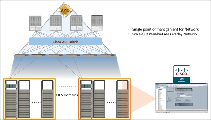
Cisco UCS Integrated Infrastructure for Big Data includes computing, storage, connectivity, and unified management capabilities to help companies manage the immense amount of data they collect today. It is built on the Cisco Unified Computing System™ (Cisco UCS) infrastructure, using Cisco UCS 6200 Series Fabric Interconnects, and Cisco UCS C-Series Rack Servers. This architecture is specifically designed for performance and linear scalability for big data workloads.
Cisco Application Centric Infrastructure (ACI) Cisco ACI is a comprehensive SDN architecture. One of the core design principles behind ACI was to provide complete visibility into the infrastructure – physical and virtual. ACI is software-defined networking (SDN) and more. Most SDN models stop at the network. ACI extends the promise of SDN—namely agility and automation—to the applications themselves. Through a policy-driven model, the network can cater to the needs of each application, with security, network segmentation, and automation at scale. And it can do so across physical and virtual environments, with a single pane of management.
Figure 1 Solution Overview
Audience
The intended audience of this document includes, but is not limited to, sales engineers, field consultants, professional services, IT managers, partner engineering and customers who want to deploy SAP HANA Vora on Cisco UCS Integrated Infrastructure for Big Data alongside their existing SAP HANA Enterprise Application landscape interconnected by Cisco ACI.
Solution Summary
This CVD describes the architecture and deployment procedures for setting up Cisco UCS C240 M4 servers, based on Cisco UCS Integrated Infrastructure for Big Data and Cisco ACI, bringing together a highly scalable architecture designed to meet a variety of scale-out application demands with seamless data integration and management integration capabilities.
This CVD describes in detail the process of creating the Application Network Profile in the ACI for Big Data application. Application Network Profile is a collection of EPGs, their connections, and the policies that define those connections described in detail later. Application Network Profiles are the logical representation of an application (here Big Data) and its interdependencies in the network fabric. Application Network Profiles are designed to be modeled in a logical way that matches the way that applications are designed and deployed. The configuration and enforcement of policies and connectivity is handled by the system rather than manually by an administrator.
The architecture and deployment procedures for deploying Hortonworks Hadoop, Apache Spark platforms and SAP HANA Vora on Cisco UCS Integrated Infrastructure for Big Data.
![]() This document talks about setting up SAP HANA Vora cluster in a single UCS domain. The System Architecture and Scaling sections below describe 3 Fabric Interconnect domains under a pair of Nexus 9396. This CVD describes the implementation of two Fabric-Interconnect domains under a pair of Nexus 9396. The third domain can be added without adding any additional network over-subscription, as there are enough ports on Nexus 9396 to support this additional domain.
This document talks about setting up SAP HANA Vora cluster in a single UCS domain. The System Architecture and Scaling sections below describe 3 Fabric Interconnect domains under a pair of Nexus 9396. This CVD describes the implementation of two Fabric-Interconnect domains under a pair of Nexus 9396. The third domain can be added without adding any additional network over-subscription, as there are enough ports on Nexus 9396 to support this additional domain.
The current version of Cisco UCS Integrated Infrastructure for Big Data offers the following configuration depending on the compute and storage requirements:
Table 1 Reference Architecture
| SAP HANA Infrastructure |
Performance Optimized |
Scaling with ACI |
| Connectivity 2 Cisco UCS 6296UP 96 Port Fabric Interconnect Scaling: · Up to 80 servers per · Up to 160 servers per 32 Cisco UCS C240 M4 Rack Servers (SFF), each with: · 2 Intel Xeon processors E5-2680 v3 CPUs · 256 GB of memory · Cisco 12-Gbps SAS Modular Raid Controller with 2GB flash-based write cache (FBWC) · 24 1.2TB 10K SFF SAS drives (460TB total) · 2 120GB (or 480GB) 6Gbps 2.5inch Enterprise Value SATA SSDs for Boot · Cisco UCS VIC 1227 (with 2 10GE SFP+ ports) |
Spine Two Cisco Nexus 9508 spine switches with 8 line cards Line card · Eight N9k-X9736PQ line cards with 36 non-blocking ports in each line card. · Total of 288 ports available to fully scale the architecture. Leaf Twenty four Cisco Nexus 9396PX leaf switches Management Three Cisco Application Policy Infrastructure Controller (Cisco APIC) for management and automation of ACI Scaling Up to 5760 servers in a fully populated pair of spines. No over-subscription within a Fabric Interconnect domain and 5.7:1 over-subscription between domains. Further Scaling Can be further expanded to a 12-spine design, allowing for tens of thousands of servers to be part of this infrastructure interconnected by a non-blocking fabric and managed through a single pane of glass. |
![]() This CVD describes the installation process of a 32 node SAP HANA Vora cluster. It is highly recommended that the size of the SSD’s for the boot drive to be 480 Gig.
This CVD describes the installation process of a 32 node SAP HANA Vora cluster. It is highly recommended that the size of the SSD’s for the boot drive to be 480 Gig.
![]() For more details on Connecting Application Centric Infrastructure (ACI) to outside Layer 2 and 3 networks can be found at: http://www.cisco.com/c/en/us/solutions/collateral/data-center-virtualization/application-centric-infrastructure/white-paper-c07-732033.html
For more details on Connecting Application Centric Infrastructure (ACI) to outside Layer 2 and 3 networks can be found at: http://www.cisco.com/c/en/us/solutions/collateral/data-center-virtualization/application-centric-infrastructure/white-paper-c07-732033.html
![]() This CVD describes the install process of SAP HANA Vora with Hortonworks HDP 2.2 and Apache Spark 1.4.1 for a 32 node (2 Master node + 30 Data nodes) of Performance Optimized Cluster configuration
This CVD describes the install process of SAP HANA Vora with Hortonworks HDP 2.2 and Apache Spark 1.4.1 for a 32 node (2 Master node + 30 Data nodes) of Performance Optimized Cluster configuration
This Cisco validated design brings together three main technologies:
1. Cisco UCS Integrated Infrastructure for Big Data
2. Cisco UCS Datacenter Solution for SAP HANA (refer to Cisco Datacenter solutions for SAP HANA)
3. Cisco Application Centric Infrastructure (ACI)

This CVD covers only the #1 and #3 of the technology components, and it can be integrated with any of existing Cisco UCS Datacenter solutions for SAP HANA.
Cisco UCS Integrated Infrastructure for Big Data
The Cisco UCS solution for Hadoop is based on Cisco UCS Integrated Infrastructure for Big Data, a highly scalable architecture designed to meet a variety of scale-out application demands with seamless data integration and management integration capabilities built using the following components:
Cisco UCS 6200 Series Fabric Interconnects
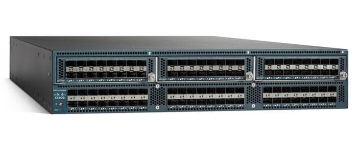
Cisco UCS 6200 Series Fabric Interconnects provide high-bandwidth, low-latency connectivity for servers, with integrated, unified management provided for all connected devices by Cisco UCS Manager. Deployed in redundant pairs, Cisco fabric interconnects offer the full active-active redundancy, performance, and exceptional scalability needed to support the large number of nodes that are typical in clusters serving big data applications. Cisco UCS Manager enables rapid and consistent server configuration using service profiles, automating ongoing system maintenance activities, such as firmware updates, across the entire cluster as a single operation. Cisco UCS Manager also offers advanced monitoring with options to raise alarms and send notifications about the health of the entire cluster.
Figure 2 Cisco UCS 6296UP 96-Port Fabric Interconnect
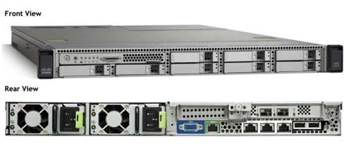
Cisco UCS C-Series Rack Mount Servers
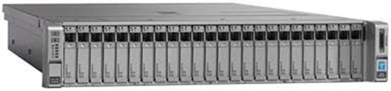
Cisco UCS C-Series Rack Mount C220 M4 High-Density Rack servers (Small Form Factor Disk Drive Model) and Cisco UCS C240 M4 High-Density Rack servers (Small Form Factor Disk Drive Model) are enterprise-class systems that support a wide range of computing, I/O, and storage-capacity demands in compact designs. Cisco UCS C-Series Rack-Mount Servers are based on Intel Xeon E5-2600 v3 product family and 12-Gbps SAS throughput, delivering significant performance and efficiency gains over the previous generation of servers. The servers use dual Intel Xeon processor E5-2600 v3 series CPUs and support up to 768 GB of main memory (128 or 256 GB is typical for big data applications) and a range of disk drive and SSD options. 24 Small Form Factor (SFF) disk drives are supported in performance-optimized option and 12 Large Form Factor (LFF) disk drives are supported in capacity-optimized option, along with 2x1 Gigabit Ethernet embedded LAN-on-motherboard (LOM) ports. Cisco UCS virtual interface cards 1227 (VICs) designed for the M4 generation of Cisco UCS C-Series Rack Servers are optimized for high-bandwidth and low-latency cluster connectivity, with support for up to 256 virtual devices that are configured on demand through Cisco UCS Manager.
Figure 3 Cisco UCS C240 M4 Rack Server
Cisco UCS Virtual Interface Cards (VICs)
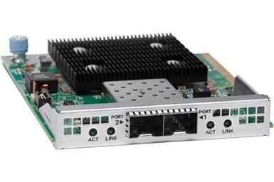
Cisco UCS Virtual Interface Cards (VICs), unique to Cisco, incorporate next-generation converged network adapter (CNA) technology from Cisco, and offer dual 10-Gbps ports designed for use with Cisco UCS C-Series Rack-Mount Servers. Optimized for virtualized networking, these cards deliver high performance and bandwidth utilization and support up to 256 virtual devices. The Cisco UCS Virtual Interface Card (VIC) 1227 is a dual-port, Enhanced Small Form-Factor Pluggable (SFP+), 10 Gigabit Ethernet and Fiber Channel over Ethernet (FCoE)-capable, PCI Express (PCIe) modular LAN on motherboard (mLOM) adapter. It is designed exclusively for the M4 generation of Cisco UCS C-Series Rack Servers and the C3160 dense storage servers.
Figure 4 Cisco UCS VIC 1227
Cisco UCS Manager
Cisco UCS Manager resides within the Cisco UCS 6200 Series Fabric Interconnect. It makes the system self-aware and self-integrating, managing all of the system components as a single logical entity. Cisco UCS Manager can be accessed through an intuitive graphical user interface (GUI), a command-line interface (CLI), or an XML application-programming interface (API). Cisco UCS Manager uses service profiles to define the personality, configuration, and connectivity of all resources within Cisco UCS, radically simplifying provisioning of resources so that the process takes minutes instead of days. This simplification allows IT departments to shift their focus from constant maintenance to strategic business initiatives.
Figure 5 Cisco UCS Manager
Cisco Application Centric Infrastructure (ACI) Overview
Cisco ACI provides the network the ability to deploy and respond to the needs of applications, both in the data center and in the cloud. The network must be able to deliver the right levels of connectivity, security, compliance, firewalls, and load balancing, and it must be able to do this dynamically and on-demand.
This is accomplished through centrally defined policies and application profiles.
The profiles are managed by the new Application Policy Infrastructure Controller [APIC] and distributed to switches, like the Cisco Nexus 9000 Series. Cisco Nexus 9000 Series Switches, and the Cisco Application Policy Infrastructure Controller (APIC) are the building blocks for Cisco ACI.
Cisco ACI is software-defined networking (SDN) plus a whole lot more. Most SDN models stop at the network. Cisco ACI extends the promise of SDN—namely agility and automation—to the applications themselves. Through a policy-driven model, the network can cater to the needs of each application, with security, network segmentation, and automation at scale. And it can do so across physical and virtual environments, with a single pane of management.
The Cisco ACI fabric supports more than 64,000 dedicated tenant networks. A single fabric can support more than one million IPv4/IPv6 endpoints, more than 64,000 tenants, and more than 200,000 10G ports. The Cisco ACI fabric enables any service (physical or virtual) anywhere, with no need for additional software or hardware gateways, to connect between the physical and virtual services, and normalizes encapsulations for Virtual Extensible Local Area Network (VXLAN) / VLAN / Network Virtualization using Generic Routing Encapsulation (NVGRE).
The Cisco ACI fabric decouples the endpoint identity and associated policy from the underlying forwarding graph. It provides a distributed Layer 3 gateway that ensures optimal Layer 3 and Layer 2 forwarding. The fabric supports standard bridging and routing semantics without standard location constraints (any IP address anywhere), and removes flooding requirements for the IP control plane Address Resolution Protocol (ARP) / Generic Attribute Registration Protocol (GARP). All traffic within the fabric is encapsulated within VXLAN.
Architectural Benefits of Using Fabric Interconnect with Cisco ACI
The Cisco ACI fabric consists of discrete components that operate as routers and switches, but is provisioned and monitored as a single entity. The operation is like a single switch and router that provides advanced traffic optimization, security, and telemetry functions, stitching together virtual and physical workloads.

Cisco Application Centric Infrastructure (ACI) and Cisco Unified Computing System (Cisco UCS), working together, can cost-effectively scale capacity, and deliver exceptional performance for the growing demands of big data processing, analytics, and storage workflows. For larger clusters and mixed workloads, Cisco ACI uses intelligent, policy-based flowlet switching and packet prioritization to deliver:
· Centralized Management for the entire Network
· Dynamic load balancing
· Dynamic Packet Prioritization
· Multi-Tenant and Mixed Workload Support
· Deep Telemetry
Centralized Management for the Entire Network
Cisco ACI treats the network as a single entity rather than a collection of switches. It uses a central controller to implicitly automate common practices such as Cisco ACI fabric startup, upgrades, and individual element configuration. The Cisco Application Policy Infrastructure Controller (Cisco APIC) is the unifying point of automation and management for the Cisco Application Centric Infrastructure (ACI) fabric. This architectural approach dramatically increases the operational efficiency of networks, by reducing the time and effort needed to make modifications to the network and, also, for root cause analysis and issue resolution
Dynamic Load Balancing
Cisco’s Application Centric Infrastructure is not only aware of the congestion points but is able to make dynamic decisions on how the traffic is switched/routed. This could be new flows that are about to start or existing long flows which could benefit from moving to a less congested route. Dynamic load balancing takes care of these decisions at run time automatically and helps utilize the links optimally – both the healthy and the congested links. This is useful in both congested link scenarios and scenarios where there are link failures. Even when there is no congestion this will maintain close to optimal distribution of traffic across the spines.
Dynamic Packet Prioritization (DPP), prioritizes short flows higher than long flows; a short flow is less than approximately 15 packets. Short flows are more sensitive to latency than long ones. Small and urgent data workloads, such as database queries, may suffer processing latency delays because larger data sets are being sent across the fabric ahead of them. This approach presents a challenge for instances in which database queries require near-real-time results.
Dynamic Packet Prioritization can improve overall application performance. Together these technologies enable performance enhancements to applications, including Big Data workloads.
Multi-Tenant and Mixed Workload Support
Cisco ACI is built to incorporate secure multi-tenancy capabilities. The fabric enables customers to host multiple concurrent Big Data clusters on a shared infrastructure. Cisco ACI provides the capability to enforce proper isolation and SLA’s for workloads of different tenants. These benefits extend beyond multiple Big Data workloads – Cisco ACI allows the same cluster to run a variety of different application workloads, not just Big Data, with the right level of security and SLA for each workload.
Deep Telemetry of Tenant and Application Network
One of the core design principles behind Cisco ACI is to provide complete visibility into the infrastructure – physical and virtual. Cisco APIC is designed to provide application and tenant health at a system level by using real-time metrics, latency details, atomic counters, and detailed resource consumption statistics
If your application is experiencing performance issues, you can drill down easily into the lowest possible granularity – be it at a switch level, line card level, or port level.
The holistic approach to correlate virtual and physical and tie that intelligence to an application or tenant level ensures that troubleshooting becomes extremely simple across your infrastructure, through a single pane of glass.
Easy Migration to 40 Gbps in the Network
Cisco QSFP BiDi technology removes 40-Gbps cabling cost barriers for migration from 10-Gbps to 40-Gbps connectivity in data center networks. Cisco QSFP BiDi transceivers provide 40-Gbps connectivity with immense savings and simplicity compared to other 40-Gbps QSFP transceivers. The Cisco QSFP BiDi transceiver allows organizations to migrate the existing 10-Gbps cabling infrastructure to 40 Gbps at no cost and to expand the infrastructure with low capital investment. Together with Cisco Nexus 9000 Series Switches, which introduce attractive pricing for networking devices, Cisco QSFP BiDi technology provides a cost-effective solution for migration from 10-Gbps to 40-Gbps infrastructure.
Cisco ACI Building blocks
Cisco ACI consists of:
· Cisco Nexus 9000 Series Switches
· Centralized policy management and Cisco Application Policy Infrastructure Controller (APIC)
Nexus 9000 Series Switches
The Nexus 9000 Series Switches offer both modular (9500 switches) and fixed (9300 switches), 1/10/40/100 Gigabit Ethernet switch configurations designed to operate in one of two modes:
· Cisco NX-OS mode for traditional architectures and consistency across the Cisco Nexus portfolio.
· Cisco ACI mode to take full advantage of the policy-driven services and infrastructure automation features of ACI.
The ACI-Ready Cisco Nexus 9000 Series provides:
· Accelerated migration to 40G: zero cabling upgrade cost with Cisco QSFP+ BiDi Transceiver Module innovation.
· Switching platform integration: Nexus 9000 Series enables a highly scalable architecture and is software upgradable to ACI.
· Streamlined application management: drastically reduce application deployment time and get end-to-end application visibility.
This architecture consists of Nexus 9500 series switches acting as the spine, and Nexus 9300 series switches as leaves.
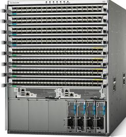
Cisco Nexus 9508 Spine Switch
The Cisco Nexus 9508 Switch offers a comprehensive feature set, high resiliency, and a broad range of 1/10/40 Gigabit Ethernet line cards to meet the most demanding requirements of enterprise, service provider, and cloud data centers. The Cisco Nexus 9508 Switch is an ACI modular spine device enabled by a non-blocking 40 Gigabit Ethernet line card, supervisors, system controllers, and power supplies.
The Cisco Nexus 9500 platform internally uses a Clos fabric design that interconnects the line cards with rear-mounted fabric modules. The Cisco Nexus 9500 platform supports up to six fabric modules, each of which provides up to 10.24-Tbps line-rate packet forwarding capacity. All fabric cards are directly connected to all line cards. With load balancing across fabric cards, the architecture achieves optimal bandwidth distribution within the chassis.
Figure 6 Cisco Nexus 9508 Switch
ACI Spine Line Card for Nexus 9508
There are multiple spine line cards supported on Nexus 9508. This architecture uses the N9K-X9736PQ: 40 Gigabit Ethernet ACI Spine Line Card.
· 36-port 40 Gigabit Ethernet QSFP+ line card
· Non-blocking
· Designed for use in an ACI spine switch role
· Works only in ACI mode
· Cannot mix with non-spine line cards
· Supported in 8-slot chassis
Figure 7 N9K-X9736PQ Line card

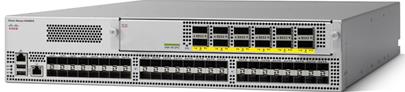
Cisco Nexus 9396 Leaf Switch
The Cisco Nexus 9396X Switch delivers comprehensive line-rate layer 2 and layer 3 features in a two-rack-unit (2RU) form factor. It supports line rate 1/10/40 GE with 960 Gbps of switching capacity. It is ideal for top-of-rack and middle-of-row deployments in both traditional and Cisco Application Centric Infrastructure (ACI)–enabled enterprise, service provider, and cloud environments.
Figure 8 Cisco Nexus 9396PX Switch
Tenant: A tenant is a logical container or a folder for application policies. This container can represent an actual tenant, an organization, an application or can just be used for the convenience of organizing information. A tenant represents a unit of isolation from a policy perspective. All application configurations in Cisco ACI are part of a tenant. Within a tenant, you define one or more Layer 3 networks (VRF instances), one or more bridge domains per network, and EPGs to divide the bridge domains.
Application Profile: Modern applications contain multiple components. For example, an e-commerce application could require a web server, a database server, data located in a storage area network, and access to outside resources that enable financial transactions. An application profile models application requirements and contains as many (or as few) End Point Groups (EPGs) as necessary that are logically related to providing the capabilities of an application.
Bridge Domain: A bridge domain represents a L2 forwarding construct within the fabric. One or more EPG can be associated with one bridge domain or subnet. A bridge domain can have one or more subnets associated with it. One or more bridge domains together form a tenant network.
End Point Group (EPG): An End Point Group (EPG) is a collection of physical and/or virtual end points that require common services and policies. An End Point Group example is a set of servers or storage LIFs on a common VLAN providing a common application function or service. While the scope of an EPG definition is much wider, in the simplest terms an EPG can be defined on a per VLAN segment basis where all the servers or VMs on a common LAN segment become part of the same EPG.
Contracts: A service contract can exist between two or more participating peer entities, such as two applications running and communicating with each other behind different endpoint groups, or between providers and consumers, such as a DNS contract between a provider entity and a consumer entity. Contracts utilize filters to limit the traffic between the applications to certain ports and protocols.
Figure 10 below covers the relationship between the ACI elements defined above. As shown in the figure, a Tenant can contain one or more application profiles and an application profile can contain one or more end point groups. The devices in the same EPG can talk to each other without any special configuration. Devices in different EPGs can talk to each other using contracts and associated filters. A tenant can also contain one or more bridge domains and multiple application profiles and end point groups can utilize the same bridge domain.
Application Policy Infrastructure Controller (APIC)
The APIC is the unified point of automation, management, monitoring, and programmability for the Cisco Application Centric Infrastructure. The APIC supports the deployment, management, and monitoring of any application anywhere, with a unified operations model for physical and virtual components of the infrastructure. The APIC programmatically automates network provisioning and Control that is based on the application requirements and policies. It is the central control engine for the broader cloud network; it simplifies management and allows flexibility in how application networks are defined and automated. It also provides northbound REST APIs. The APIC is a distributed system that is implemented as a cluster of many controller instances.
Figure 9 APIC Appliance
Cisco ACI Topology
Cisco ACI topology is spine-leaf architecture. Each leaf is connected to each spine. It uses internal routing protocol; Intermediate System to Intermediate System (IS-IS) to establish IP connectivity throughout the fabric among all the nodes including spine and leaf. To transport tenant traffic across the IP fabric, integrated VxLAN overlay is used. The broadcast ARP traffic coming from the end point or hosts to the leaf are translated to unicast ARP in the fabric.
The forwarding is done as a host based forwarding. In the leaf layer the user information such as username, IP address, locations, policy groups etc., are decoupled from the actual forwarding path and encode them into the fabric VxLAN header and is forwarded to the desired destination.
Each spine has the complete forwarding information about the end hosts that are connected to the fabric and on every leaf have the cached forwarding information. The leaf only needs to know the hosts it needs to talk to. For example if Server Rack-1 has to send some information to Server Rack-2, When packet comes in the ingress leaf (LEAF_1) it will encapsulate the information into the VxLAN header and forward that information to LEAF_2. If the LEAF_1 does not have information about the LEAF_2, it uses Spine as a proxy and since Spine has all the complete information about the entire end host connected to the fabric, it will resolve the egress leaf and forward the packet to the destination.
To the outside world, routing protocols can be used to learn outside prefixes or static routing can be used instead. The outside learned routes will be populated into the fabric or to the other leafs with Multiprotocol BGP (M-BGP). In M-BGP topology the spine nodes acts as route reflectors.
The Network topology of ACI is as depicted below:
Figure 10 Network Topology Based on Cisco ACI
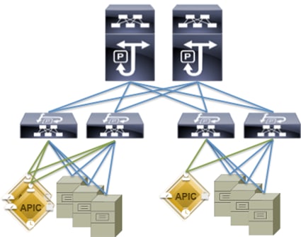
The Cisco ACI infrastructure incorporates the following components:
1. Two Cisco Nexus 9508 Spine Switch
2. Cisco ACI Spine Line Card for Nexus 9508
3. Cisco Nexus 9396 Leaf Switch for Data Traffic
4. Cisco APIC-L1-Cluster with three APIC-L1 appliances
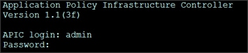
Once the configuration is completed, the APIC will Boot its APIC IOS Image and will ask for the login information. The default username is “admin” and the password is the one that was set during the initial configuration.
Cisco UCS Datacenter Solution for SAP HANA
Cisco and SAP have partnered to deliver an optimized UCS architecture for running SAP HANA, which provides fast transaction processing with real-time insights. Cisco UCS provides high-bandwidth connectivity between SAP HANA nodes and the persistency layer; this also allows SAP HANA deployments to scale more easily and transparently. Further, the Cisco UCS technology allows customers to scale dynamically as requirements and demand change.
Running SAP HANA on the Cisco UCS server platform offers the opportunity to reduce the hardware and maintenance costs associated with running multiple data warehouses, operational systems, and analytical systems. A principal design element of UCS is to break away from old static IT datacenter models and deliver on a new IT model that pools server, storage, and networking resources into a flexible physical and/or virtualized environment that can be provisioned (or reprovisioned) as workloads and business demands require.
This design guide provides an opportunity to integrate with any of the existing Cisco Datacenter Solution for SAP HANA CVD). The following are the Cisco UCS based designs guides that can be used in conjunction with this CVD.
| SAP Solutions on Cisco UCS |
|
(Used in this CVD for reference) |
Architecture referenced in this guide (Flexpod Datacenter for SAP Solution with Cisco ACI)
The FlexPod Datacenter solution for SAP HANA with NetApp FAS storage provides an end-to-end architecture with Cisco, NetApp and VMware technologies that demonstrate support for multiple SAP HANA workloads with high availability and server redundancy. The architecture uses UCS Manager with combined Cisco UCS B-Series and C-Series Servers with NetApp FAS 8000 series storage attached to the Nexus 9396PX switches for NFS access and iSCSI. The C-Series Rack Servers are connected directly to Cisco UCS Fabric Interconnect with single-wire management feature. This infrastructure is deployed to provide PXE and iSCSI boot options for hosts with file-level and block-level access to shared storage. VMware vSphere 5.5 is used as server virtualization architecture.
The figure below shows the FlexPod Datacenter for SAP Solution with ACI. It highlights the FlexPod hardware components and the network connections for a configuration with IP- based storage.
Figure 11 FlexPod Datacenter for SAP Solution with ACI
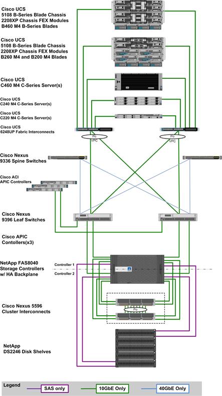
The reference hardware configuration includes:
Cisco Unified Computing System
· 2 x Cisco UCS 6248UP 48-Port or 6296UP 96-Port Fabric Interconnects
· 2 x Cisco UCS 5108 Blade Chassis with 2 x Cisco UCS 2204 Fabric Extenders with 4x 10 Gigabit Ethernet interfaces
· 2 x Cisco UCS B460 M4 High-Performance Blade Servers with 2x Cisco UCS Virtual Interface Card (VIC) 1280 and 2x Cisco UCS Virtual Interface Card (VIC) 1240
· 2 x Cisco UCS B260 M4 High-Performance Blade Servers with 1x Cisco UCS Virtual Interface Card (VIC) 1280 and 1x Cisco UCS Virtual Interface Card (VIC) 1240
· 1 x Cisco UCS C460 M4 High-Performance Rack-Mount Servers with 2x Cisco UCS Virtual Interface Card (VIC) 1225.
· 4 x Cisco UCS B200 M4 High-Performance Blade Servers with Cisco UCS Virtual Interface Card (VIC) 1340
· 1 x Cisco UCS C220 M4 High-Performance Blade Servers with Cisco UCS Virtual Interface Card (VIC) 1225
· 1 x Cisco UCS C240 M4 High-Performance Blade Servers with Cisco UCS Virtual Interface Card (VIC) 1225
· 2 x Cisco UCS C220 M3 for Management Servers with Cisco UCS Virtual Interface Card (VIC) 1225 and RAID controller with Internal Disks
Cisco ACI
· 2 x Cisco Nexus 9396 Leaf Switch for 10 Gigabit Ethernet connectivity between the two UCS Fabric Interconnects
· 2 x Cisco Nexus 9336 Spine Switch for 40 Gigabit Ethernet connectivity for ACI fabric
· 3 x Cisco APIC Controllers for centralized management of ACI fabric
NetApp FAS8040 Storage
· NetApp FAS8040HA Storage Clustered Data ONTAP
· 4 x NetApp Disk Shelf DS2246 with 24x 600GB 10k 2,5” SAS Disks
· 2 x Cisco Nexus 5596 Switch for FAS 8000 Cluster Interconnect
· Server virtualization is achieved by VMware vSphere 5.5.
Although this is the base design, each of the components can be scaled easily to support specific business requirements. Additional servers or even blade chassis can be deployed to increase compute capacity without additional Network components. Two Cisco UCS 6248UP, 48 port Fabric interconnect can support up to:
· 20 Cisco UCS B-Series B460 M4 or 40 B260 M4 Server with 10 Blade Server Chassis
· 20 Cisco UCS C460 M4 Sever
· 40 Cisco UCS C220 M4/C240 M4 Server
For every eight Cisco UCS Server, One NetApp FAS8040 HA pair with Clustered Data ONTAP is required to meet the SAP HANA storage performance. While adding compute and storage for scaling, it is required to increase the network bandwidth between Cisco UCS Fabric Interconnet and Cisco Nexus 9000 switch. Addition of each NetApp Storage requires additional four 10 GbE connectivity from each Cisco UCS Fabric Interconnect to Cisco Nexus 9000 switches.
![]() The number of Cisco UCS C-Series or Cisco UCS B-Series Servers and the NetApp FAS storage type depends on the number of SAP HANA instances. SAP specifies the storage performance for SAP HANA, based on a per server rule independent of the server size. In other words, the maximum number of servers per storage will remain the same if you want to use Cisco UCS B200 M4 with 192GB physical memory or Cisco UCS B460 M4 with 2TB physical memory.
The number of Cisco UCS C-Series or Cisco UCS B-Series Servers and the NetApp FAS storage type depends on the number of SAP HANA instances. SAP specifies the storage performance for SAP HANA, based on a per server rule independent of the server size. In other words, the maximum number of servers per storage will remain the same if you want to use Cisco UCS B200 M4 with 192GB physical memory or Cisco UCS B460 M4 with 2TB physical memory.
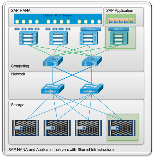
Figure 12 shows a block diagram of a complete SAP Landscape built using the FlexPod architecture. It composed of multiple SAP HANA systems and SAP applications with shared infrastructure as illustrated in the figure. The FlexPod Datacenter reference architecture for SAP solutions supports SAP HANA system in both Scale-Up mode (bare metal/ virtualization) and Scale-Out mode with multiple servers with the shared infrastructures.
Virtualized SAP application servers with VMware vSphere 5.5 allows application servers to run on the same infrastructure as the SAP HANA database. The FlexPod datacenter solution manages the communication between the application server and the SAP HANA database. This approach enhances system performance by improving bandwidth and latency. It also improves system reliability by including the application server in the disaster-tolerance solution with the SAP HANA database.
Figure 12 Shared Infrastructure Block Diagram
Flexpod Datacenter for SAP Solution with Cisco ACI describes detailed procedures for the reference design and outlines the network, compute and storage configurations and deployment process for running SAP HANA on FlexPod platform.
Hortonworks Data Platform (HDP 2.2)
The Hortonworks Data Platform 2.2 (HDP 2.2) is an enterprise-grade, hardened Apache Hadoop distribution that enables you to store, process, and manage large data sets.
Apache Hadoop is an open-source software framework that allows for the distributed processing of large data sets across clusters of computers using simple programming models. It is designed for high-availability and fault-tolerance, and can scale from a single server up to thousands of machines.
The Hortonworks Data Platform combines the most useful and stable versions of Apache Hadoop and its related projects into a single tested and certified package. Hortonworks offers the latest innovations from the open source community, along with the testing and quality you expect from enterprise-quality software.
The Hortonworks Data Platform is designed to integrate with and extend the capabilities of existing investments in data applications, tools, and processes. With Hortonworks, one can refine, analyze, and gain business insights from both structured and unstructured data – quickly, easily, and economically.
Key Features of HDP 2.2
Hortonworks Data Platform enables Enterprise Hadoop: the full suite of essential Hadoop capabilities that are required by the enterprise and that serve as the functional definition of any data platform technology. This comprehensive set of capabilities is aligned to the following functional areas: Data Management, Data Access, Data Governance and Integration, Security, and Operations.
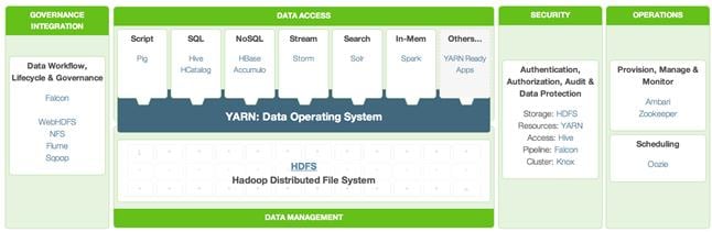
HDP 2.2 incorporates many new innovations that have happened in Hadoop and its supporting ecosystem of projects. Some of the key projects are listed below
Enterprise SQL at Scale in Hadoop
While YARN has allowed new engines to emerge for Hadoop, one of the popular integration point with Hadoop continues to be SQL and Apache Hive is still the defacto standard.
New capabilities in HDP 2.2 include:
· Updated SQL Semantics for Hive Transactions for Update and Delete: ACID transactions provide atomicity, consistency, isolation, and durability. This helps with streaming and baseline update scenarios for Hive such as modifying dimension tables or other fact tables.
· Improved Performance of Hive with a Cost Based Optimizer: The cost based optimizer for Hive, uses statistics to generate several execution plans and then chooses the most efficient path as it relates system resources required to complete the operation. This presents a major performance increase for Hive.
Apache Hive
Apache Hive is a data warehouse infrastructure built on top of Hadoop for providing data summarization, query, and analysis. Apache Hive supports analysis of large datasets stored in Hadoop’s HDFS and compatible file systems. It provides an SQL-like language called HiveQL(Hive Query Language) while maintaining full support for map/reduce.
Apache Tez
Apache Tez is an extensible framework for building high performance batch and interactive data processing applications, coordinated by YARN in Apache Hadoop. Tez improves the MapReduce paradigm by dramatically improving its speed, while maintaining MapReduce’s ability to scale to petabytes of data. Important Hadoop ecosystem projects like Apache Hive and Apache Pig use Apache Tez, as do a growing number of third party data access applications developed for the broader Hadoop ecosystem.
Kafka for Processing the Internet of Things
Apache Kafka has quickly become the standard for high-scale, fault-tolerant, publish-subscribe messaging system for Hadoop. It is often used with Storm and Spark so as to stream events in to Hadoop in real time and its application within the “internet of things” uses cases is tremendous.
Apache Flume
Flume is a distributed, reliable, and available service for efficiently collecting, aggregating, and moving large amounts of streaming data into the Hadoop Distributed File System (HDFS). It has a simple and flexible architecture based on streaming data flows; and is robust and fault tolerant with tunable reliability mechanisms for failover and recovery.
Apache Sqoop
Sqoop is a tool designed for efficiently transferring bulk data between Apache Hadoop and structured datastores such as relational databases. Sqoop imports data from external structured datastores into HDFS or related systems like Hive and HBase. Sqoop can also be used to extract data from Hadoop and export it to external structured datastores such as relational databases and enterprise data warehouses. Sqoop works with relational databases such as: Teradata, Netezza, Oracle, MySQL, Postgres, and HSQLDB.
Apache Knox
Knox provides perimeter security so that the enterprise can confidently extend Hadoop access to more of those new users while also maintaining compliance with enterprise security policies. Knox also simplifies Hadoop security for users who access the cluster data and execute jobs. It integrates with prevalent identity management and SSO systems and allows identities from those enterprise systems to be used for seamless, secure access to Hadoop clusters.
The Hortonworks Data Platform is the foundation for the next-generation enterprise data architecture – one that addresses both the volume and complexity of today’s data.
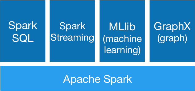
Apache Spark 1.4.1
Apache Spark is a fast, in-memory data processing engine with elegant and expressive development APIs in Scala, Java, and Python that allow data workers to efficiently execute machine learning algorithms that require fast iterative access to datasets. Spark on Apache Hadoop YARN enables deep integration with Hadoop and other YARN enabled workloads in the enterprise.
With YARN, Hadoop can now support many types of data and application workloads; Spark on YARN becomes yet another workload running against the same set of hardware resources.
HDP’s YARN-based architecture enables multiple applications to share a common cluster and dataset while ensuring consistent levels of service and response. Now Spark is one of the many data access engines that works with YARN and that is supported in an HDP enterprise data lake. Spark on YARN provides a very powerful way to derive value from any data, any application, anywhere.
![]() Note: For more information visit http://spark.apache.org/
Note: For more information visit http://spark.apache.org/
SAP HANA Vora
SAP HANA Vora™ is an in-memory query engine that plugs into the Apache Spark execution framework to provide enriched interactive analytics on Hadoop. SAP HANA Vora extends the HANA–like analytics experience to ALL data. SAP HANA Vora plugs into the Apache SPARK framework which is part of Apache Hadoop, and allows us to bring OLAP-like analytics and business semantics of the data in and around the Hadoop ecosystem. This is important- to reach meaningful contextual information when new unstructured data such as data from IoT sensors, machine telemetry or from social media, comes together with business data such as financial records, business goals, maintenance records, and employment data. It is only when these two different data sets meet, that business meaning is made. Meaningful business results require that we embrace ALL data, in a contextual way, to drive analytics driven outcomes.
SAP HANA Vora provides the following features:
· In-memory query engine running on Apache Spark execution framework
· Compiled queries for accelerated processing across nodes
· Enhanced Spark SQL semantics with hierarchies for analytical processing
· Enhanced mashup application programming interface (API) for easier access to enterprise application data for machine learning workloads
SAP HANA Vora can benefit customers in industries where highly interactive big data analytics in business process context is paramount, such as financial services, telecommunications, healthcare and manufacturing. Examples include:
· Mitigate risk and fraud by detecting new anomalies in financial transactions and customer history data.
· Optimize telecommunication bandwidth by analyzing traffic patterns to help avoid network bottlenecks and improve network quality of service (QoS).
· Deliver preventive maintenance and improve product re-call process by analyzing bill-of-material, services records and sensor data together.
Requirements
Physical Layout for the Solution
The physical layout for the solution is shown in Table 2 below. Each rack consists of two vertical PDUs. The solution consists of 3 Cisco R42610 racks. The Nexus 9396 leaf switch and the Fabric Interconnect s are mounted on rack2, the APIC appliances are distributed across rack1 to rack3. Similarly, nexus 9508 spine switch is mounted in rack2 for easier cabling between the spine and leaf switches. All the Switches and UCS Servers are dual connected to vertical PDUs for redundancy; thereby, ensuring availability during power source failure.
|
|
Rack 1 |
Rack 2 |
Rack 3 |
| 1. |
N9K-C9396PX |
FI-A |
N9K-C9396PX |
| 2. |
|||
| 3. |
|
FI- B |
|
| 4. |
|||
| 5. |
|
|
|
| 6. |
|
||
| 7. |
|
|
|
| 8. |
|
||
| 9. |
APIC-L1 |
APIC-L1 |
APIC-L1 |
| 10. |
|||
| 11. |
UCS C240M4
|
|
UCS C240M4
|
| 12. |
|||
| 13. |
UCS C240M4
|
|
UCS C240M4
|
| 14. |
|||
| 15. |
UCS C240M4
|
|
UCS C240M4
|
| 16. |
|||
| 17. |
UCS C240M4
|
N9k-C9508 |
UCS C240M4
|
| 18. |
|||
| 19. |
UCS C240M4
|
UCS C240M4
|
|
| 20. |
|||
| 21. |
UCS C240M4
|
UCS C240M4
|
|
| 22. |
|||
| 23. |
UCS C240M4
|
UCS C240M4
|
|
| 24. |
|||
| 25. |
UCS C240M4
|
UCS C240M4
|
|
| 26. |
|||
| 27. |
UCS C240M4
|
UCS C240M4
|
|
| 28. |
|||
| 29. |
UCS C240M4
|
UCS C240M4
|
|
| 30. |
N9k-C9508 |
||
| 31. |
UCS C240M4
|
UCS C240M4
|
|
| 32. |
|||
| 33. |
UCS C240M4
|
UCS C240M4
|
|
| 34. |
|||
| 35. |
UCS C240M4
|
UCS C240M4
|
|
| 36. |
|||
| 37. |
UCS C240M4
|
UCS C240M4
|
|
| 38. |
|||
| 39. |
UCS C240M4
|
UCS C240M4
|
|
| 40. |
|||
| 41. |
UCS C240M4
|
UCS C240M4
|
|
| 42. |
Software Distributions and Versions
The required versions of software distributions are listed below.
Red Hat Enterprise Linux (RHEL)
The operating system supported is Red Hat Enterprise Linux 6.6. For more information visit http://www.redhat.com
Hortonworks Data Platform (HDP 2.2)
The Hortonworks Data Platform supported is HDP 2.0. For more information visit http://www.hortonworks.com.
Software Versions
The software versions tested and validated in this document are shown in Table 3 below.
| Layer |
Component |
Version or Release |
| Network |
Cisco ACI OS |
11.1(3f) |
| APIC OS |
1.1 (3f) |
|
| Compute |
Cisco UCS 6296UP |
UCS 2.2(5b) |
| Cisco UCS VIC1227 Firmware |
4.0(1d) |
|
| Cisco UCS VIC1227 Driver |
2.1.1.66 |
|
| Storage |
LSI SAS 3108 |
24.5.0-0020 |
| Software
|
Red Hat Enterprise Linux Server |
6.6 (x86_64) |
| Cisco UCS Manager |
2.2(5b) |
|
| HDP |
2.2 |
|
| Ambari |
1.7 |
|
|
|
Spark |
1.4.1 (preview) |
|
|
SAP HANA Vora |
1.1 |
![]() The latest drivers can be downloaded from the link: https://software.cisco.com/download/release.html?mdfid=283862063&flowid=25886&softwareid=283853158&release=1.5.7d&relind=AVAILABLE&rellifecycle=&reltype=latest
The latest drivers can be downloaded from the link: https://software.cisco.com/download/release.html?mdfid=283862063&flowid=25886&softwareid=283853158&release=1.5.7d&relind=AVAILABLE&rellifecycle=&reltype=latest
![]() The Latest Supported RAID controller Driver is already included with the RHEL 6.6 operating system.
The Latest Supported RAID controller Driver is already included with the RHEL 6.6 operating system.
![]() Cisco UCS C240/C220 M4 Rack Servers are supported from Cisco UCS firmware 2.2(3d) onward.
Cisco UCS C240/C220 M4 Rack Servers are supported from Cisco UCS firmware 2.2(3d) onward.
System Architecture
The system architecture includes Cisco UCS C240 M4 servers, based on Cisco UCS Integrated Infrastructure for Big Data.
The ACI fabric consists of three major components: The Application Policy Infrastructure Controller (APIC), spine switches, and leaf switches. These three components handle both the application of network policy and the delivery of packets.
The system architecture consists of a pair of FIs connecting to ACI having two N9508 switches acting as a Spine and two Nexus 9396 as the leaf switches and three APIC-L1 as an APIC appliance.
The following explains the system architecture:
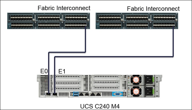
· The 32 server are rack mounted and are connected to a pair of FI representing a domain through 10GE link (dual 10GE link to a pair of FI)
· This UCS domain is connected to a pair of Nexus 9396 which is the ACI Fabric leaf nodes. Here 10GEx16 links from each FI are connected to Nexus 9396. This is done through a port-channel of 8 links connected to each of the Nexus 9396
· Nexus 9396 receives the 16x10GE from each pair of FI as a vPC (Virtual Port-Channel), i.e., 8 ports coming from each single FI as an uplink to the leaf. There are 2 vPC for this UCS domain in each of 9396 connecting to the pair of FIs.
· Each leaf is connected to Spines via 12 x 40 Gig connectivity cables.
· The three APIC’s are connected to two leaves (Nexus 9396) via 10 gig SFP cable.
Figure 13 below shows the overall system architecture and physical layout of the solution.
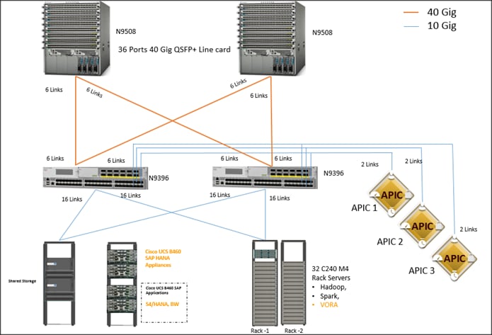
Figure 14 below show the connectivity between the leaf switches and fabric interconnect, where port channeling has been configured on Fabric Interconnect. This port channeling helps to aggregate the bandwidth towards the uplink leaf switches.
Figure 14 Fabric Interconnect Connectivity
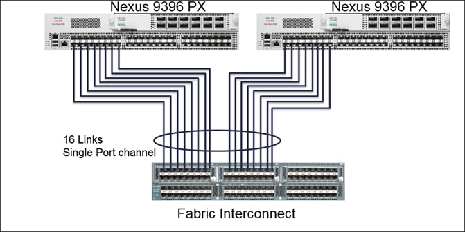
Figure 15 below shows the connectivity between the leaf switches and fabric interconnect, where vPC has been configured on leaf switches through the APIC. These vPC ports are the same ports that were configured as port-channels in the fabric interconnect.
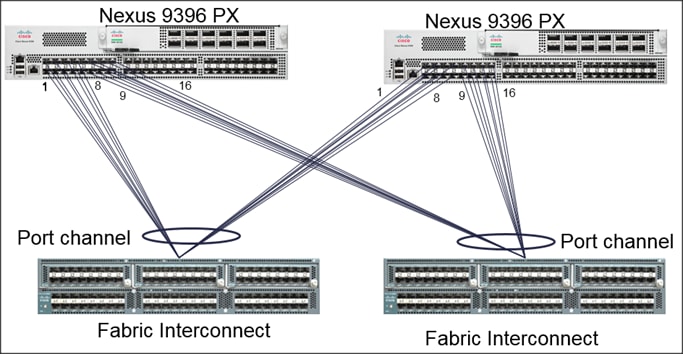
Figure 16 below shows the connectivity between the one C240 M4 servers and two Fabric.
Figure 16 Cisco UCS C240 M4 Server Connectivity
Scaling the Architecture
The UCS Servers are directly connected to the Fabric Interconnect (FI) which connects to the Nexus 9K switches. This mode allows using the UCS Manager capabilities in FI for provisioning the servers.
Scaling the Architecture Further with Additional Spine Switches
The physical network of the Cisco Application Centric Infrastructure is built around leaf-spine architecture. It is possible to scale this infrastructure, immensely, by adding additional spine switches. The ACI infrastructure supports up to 12 spine switches.
Figure 17 Cisco ACI Fabric with Multiple Spine Switches
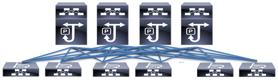
With a 12-spine design, each leaf switch can be connected to up to 12 spine switches. Allowing for tens of thousands of servers to be part of this infrastructure – being interconnected by a non-blocking fabric.
SAP HANA and SAP HANA VORA scalability
The Base configuration 4 HANA Appliances (B460 M4/C460 M4 servers) + 32 C240 M4 (Cisco UCS Integrated Infrastructure for Big Data).
Recommended building block is made up of a set of 16 C240 M4 servers for every two HANA servers.
![]() The VORA tier can scale-out independent of the HANA tier if necessary.
The VORA tier can scale-out independent of the HANA tier if necessary.
| SAP HANA Tier (B460/C460) |
SAP HANA Vora Tier (C240 M4) |
| 4 servers |
32 servers |
| 8 servers |
64 servers |
| 16 servers |
128 servers |
Network Configuration
The network configuration includes configuring the APIC, leaf, spine switches and Fabric Interconnect and deploying various application profiles and policies. In order to achieve this we first need to register the connected Nexus 9K switches to the APIC so that these switches become the part of the ACI fabric. Once the switch is registered the communication between the spine and leaf are completed.
The admin is the only account enabled by default after the APIC is configured and it is always a good practice to create other user accounts with different privilege levels to make the APIC and the network secure. For this purpose we create a local or remote user depending on requirement.
Adding a management access is required in the ACI to let ACI know about any physical or virtual domain that is connected to it. By adding management access, APIC will control the physical interface and assign the policies to this interface. This is achieved by configuring Attachable Access Entity Profile (AEP). AEP requires having the domain and VLAN pool that the ACI fabric will be using to communicate with various devices attached to it.
![]() For more detail on AEP please refer “Adding Management Access” section.
For more detail on AEP please refer “Adding Management Access” section.
In this CVD, two pair of FIs representing two domains are connected to the pair of leaf switch. The uplink in the FIs is connected to the leaf via the port channeling (created in FI) and vPC is created at the leaf switches. The vPC allows single device to use a PortChannel across two upstream devices, eliminating Spanning Tree Protocol blocked ports which in turns provides a loop-free topology. With the use of vPC provides high availability and link-level resiliency.
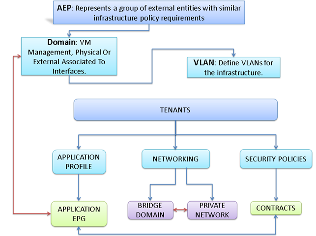
Depending on the number of VLANs created in the FI, to trunk these vlans across the ACI fabric an Attachable Entity Profile (AEP) is required. An AEP provisions the VLAN pool (and associated VLANs) on the leaf, these VLAN pools are defined under the domain created within the AEP. A domain could be various external entities such as bare metal servers, hypervisors, VM management, Layer 2 or Layer 3 domains. The VLANs are not actually enabled on the port. No traffic flows unless an EPG is deployed on the port. An EPG acts as a separate entity which is analogous to VLAN. A tenant needs to be created before an EPG is defined.
A tenant contains policies that enable qualified users domain-based access control. Application profile, security policies and network are the elements of Tenants. An EPG for each VLAN is created under the application profile. Since EPG represent VLANs, a switch virtual interface (SVI) is needed to provide the Layer 3 processing for packets from all switch ports associated with the VLAN. A bridge domain needs to be created which acts as switch virtual interface (SVI) for this purpose. Now, for the inter-Vlan communication, contracts need to be created to achieve communication among each EPG. Contracts are policies that enable inter-End Point Group (inter-EPG) communication. These policies are the rules that specify communication between application tiers.
![]() For more details on Tenant please refer to the “Adding Tenant” section.
For more details on Tenant please refer to the “Adding Tenant” section.
The relationship between the AEP, Tenants and its elements is shown in Figure 18 below.
Figure 18 AEP, Tenants, and Elements
IP Address Assignment
The IP address of UCS and ACI management are configured as out of band management access through the management switch.
APIC-1 10.0.141.8/24 (Primary)
APIC-2 10.0.141.9/24
APIC-3 10.0.141.10/24
Pod - 1
UCSM 10.0.141.20/24
FI-A 10.0.141.21/24
FI-B 10.0.141.22/24
KVM 10.0.141.11/24 – 10.0.141.90/24
Table 8 VLan ID and IP Address
| Vlan ID |
Tenant Production |
| 10 (Mgmt) |
172.16.10.0/24 |
| 11 (Data1) |
172.16.11.0/24 |
| 12 (Data2) |
172.16.12.0/24 |
Configuration Parameters for the Tenants
Tenant: Production
Private Network: Production
 Bridge Domain: Prod_Mgmt
![]() Prod_Data1
Prod_Data1
 Prod_Data2
App. Profile: Production
App. EPG: Prod_Mgmt
Prod_Data1
Prod_Data2
Configuration of APIC
This section describes loading and configuring the APIC.
Once the APIC appliance is booted for the first time, the APIC console presents a series of initial setup options. For many options, you can press Enter to choose the default setting that is displayed in brackets. At any point in the setup dialog, you can restart the dialog from the beginning by pressing Ctrl-C.
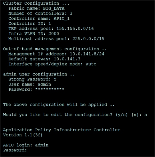
The initial configuration of the APIC is shown below.
1. Enter the fabric name [ACI Fabric1]:
2. Enter the number of controllers in the fabric (1-9) [3]:3
3. Enter the controller ID (1-3) [1]:1
4. Enter the controller name [apic1]:APIC_1
5. Enter address pool for TEP addresses [10.0.0.0/16]: 155.155.0.0/16
6. Enter the VLAN ID for infra network (1-4094) [4]: 2000
7. Out-of-band management configuration
8. Enter the IP address for out-of-band management: 10.0.141.8/24
9. Enter the IP address of the default gateway [None]: 10.0.141.1
10. Administrator user configuration.
11. Enable strong passwords? [Y]
12. Enter the password for admin
A screenshot of the configuration is shown below.
13. Repeat steps 1 through 12 for the additional 2 APICs with unique IP addresses for each of them.
Once the configuration is completed, the APIC will Boot its APIC IOS Image and will ask for the login information. The default username is “admin” and the password is the one that was set during the initial configuration.

Switch Discovery with the APIC
The APIC is a central point of automated provisioning and management for all the switches that are part of the ACI fabric. A single data center might include multiple ACI fabrics, each with their own APIC cluster and Cisco Nexus 9000 Series switches that are part of the fabric. To ensure that a switch is managed only by a single APIC cluster, each switch must be registered with that specific APIC cluster that manages the fabric. The APIC discovers new switches that are directly connected to any switch it currently manages. Each APIC instance in the cluster first discovers only the leaf switch to which it is directly connected. After the leaf switch is registered with the APIC, the APIC discovers all spine switches that are directly connected to the leaf switch. As each spine switch is registered, that APIC discovers all the leaf switches that are connected to that spine switch. This cascaded discovery allows the APIC to discover the entire fabric topology in a few simple steps.
Switch Registration with the APIC Cluster
Once the switch is discovered by the APIC cluster it needs to be registered in the APIC to make it as a part of the fabric.
Prerequisite: All switches must be physically connected and booted with the correct ACI Image.
Using a web browser connect to the out-of-band management ip address [10.0.141.8] configured in the initial configuration.
1. On the menu bar, choose FABRIC > INVENTORY. In the Navigation pane, choose the appropriate pod.
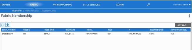
2. In the Navigation pane, expand the pod, and click Fabric Membership.
In the Work pane, in the Fabric Membership table, a single leaf switch is displayed with an ID of 0. It is the leaf switch that is connected to APIC.
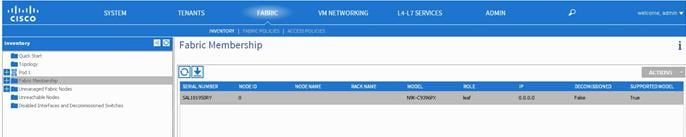
To configure the ID, double-click the leaf switch row, and perform the following actions:
3. In the ID field, add the appropriate ID (leaf1 is ID 101, leaf2 is ID 102 and leaf3 is ID103).
The ID must be a number that is greater than 100 because the first 100 IDs are for APIC appliance nodes.
4. In the Switch Name field, add the name of the switch, and click Update.
After an ID is assigned, it cannot be updated. The switch name can be updated by double-clicking the name and updating the Switch Name field.
![]() The Success dialog box is displayed. An IP address gets assigned to the switch, and in the Navigation pane, the switch is displayed under the pod.
The Success dialog box is displayed. An IP address gets assigned to the switch, and in the Navigation pane, the switch is displayed under the pod.
5. Monitor the Work pane until one or more spine switches appear.
6. To configure the ID, double-click the spine switch row and perform the following actions:
a. In the ID field, add the appropriate ID (spine1 is ID 201 and spine 2 is ID 202).
The ID must be a number that is greater than 100.
7. In the Switch Name field, add the name of the switch, and click Update.
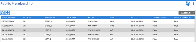
The Success dialog box is displayed. An IP address gets assigned to the switch, and in the Navigation pane, the switch is displayed under the pod. Wait until all remaining switches appear in the Node Configurations table.
8. For each switch listed in the Fabric Membership table, perform the following steps:
b. Double-click the switch, enter an ID and a Name, and click Update.
c. Repeat for the next switch in the list.
Validating the Switches
1. On the menu bar, choose FABRIC > INVENTORY, and in the Navigation pane, under Pod 1, expand Fabric Membership.
2. The switches in the fabric are displayed with their node IDs. In the Work pane, all the registered switches are displayed with the IP addresses that are assigned to them.
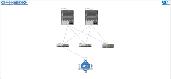
Validating the Fabric Topology
1. On the menu bar, choose FABRIC > INVENTORY.
2. In the Navigation pane, choose the pod that you want to view.
3. In the Work pane, click the TOPOLOGY tab.
The displayed diagram shows all attached switches, APIC instances, and links.
4. (Optional) To view the port-level connectivity of a leaf switch or spine switch, double-click its icon in the topology diagram.
5. To return to the topology diagram, in the upper left corner of the Work pane click the Previous View icon.
6. (Optional) To refresh the topology diagram, in the upper left corner of the Work pane, click the Refresh icon.
![]()
Creating User Accounts
The admin is the only user when the system starts. The APIC supports a granular, role-based access control system where user accounts can be created with various roles including non-admin users with fewer privileges.
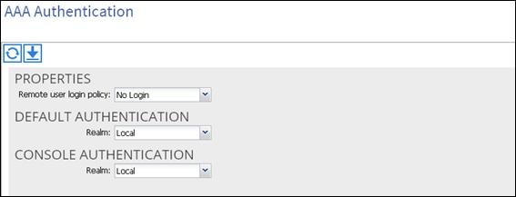
1. On the menu bar, choose ADMIN > AAA
2. In the Navigation pane, click AAA Authentication.
3. In the Work pane, the AAA Authentication dialog box is displayed.
4. Verify that in the default Authentication field, the Realm field displays as Local.
In the Navigation pane, right-click Create Local User.
1. In the Navigation pane, expand Security Management > Local Users.
The admin user is present by default.
The Create Local User dialog box opens.
2. Under the Security dialog box, choose the desired security domain for the user, and click next.
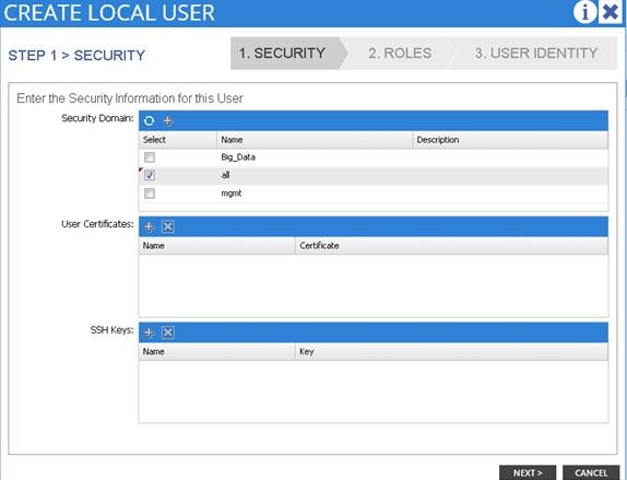
The Roles dialog box opens.
3. In the Roles dialog box, click the radio buttons to choose the roles for your user, and click next. You can provide read-only or read/write privileges.
In the User Identity dialog box, perform the following actions:
4. In the Login ID field, add an ID.
a. In the Password field, type the password.
b. In the Confirm Password field, confirm the password.
c. Click Finish.
d. Type other parameters if desired.

5. In the Navigation pane, click the name of the user that you created. In the Work pane, expand the + sign next to the user in the Security Domains area.
The access privileges for the user are displayed.
Adding Management Access
Attach Entity Profiles (AEP)
The ACI fabric provides multiple attachment points that connect through leaf ports to various external entities such as bare metal servers, hypervisors, Layer 2 switches (for example, the Cisco UCS Fabric Interconnect), and Layer 3 routers (for example Cisco Nexus 7000 Series switches). These attachment points can be physical ports, port channels, or a virtual port channel (vPC) on the leaf switches.
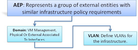
An attachable entity profile (AEP) represents a group of external entities with similar infrastructure policy requirements. The infrastructure policies consist of physical interface policies, for example, Cisco Discovery Protocol (CDP), Link Layer Discovery Protocol (LLDP), maximum transmission unit (MTU), and Link Aggregation Control Protocol (LACP).
An AEP is required to deploy any VLAN pools on the leaf switches. It is possible to reuse the encapsulation pools (for example, VLAN) across different leaf switches. An AEP implicitly provides the scope of the VLAN pool (associated to the VMM domain) to the physical infrastructure.
![]() An AEP provisions the VLAN pool (and associated VLANs) on the leaf. The VLANs are not actually enabled on the port. No traffic flows unless an EPG is deployed on the port. Without VLAN pool deployment using an AEP, a VLAN is not enabled on the leaf port even if an EPG is provisioned.
An AEP provisions the VLAN pool (and associated VLANs) on the leaf. The VLANs are not actually enabled on the port. No traffic flows unless an EPG is deployed on the port. Without VLAN pool deployment using an AEP, a VLAN is not enabled on the leaf port even if an EPG is provisioned.
![]() A particular VLAN is provisioned or enabled on the leaf port based on EPG events either statically binding on a leaf port or based on VM events from external controllers such as VMware vCenter.
A particular VLAN is provisioned or enabled on the leaf port based on EPG events either statically binding on a leaf port or based on VM events from external controllers such as VMware vCenter.
![]() A leaf switch does not support overlapping VLAN pools. Different overlapping VLAN pools must not be associated with the same AEP.
A leaf switch does not support overlapping VLAN pools. Different overlapping VLAN pools must not be associated with the same AEP.
Configuring the VPC Ports for the Fabric Interconnect
In order to configure vPC we need to create a CDP Policy, an LLDP Policy and a LACP Policy that can be applied to the vPC ports.
· The APIC does not manage fabric interconnects and the rack servers, so these services must be configured from UCSM.
· Create VLAN pools that are associated on the fabric interconnect uplink to the leaf switch on the fabric interconnect.
· Cisco UCS C-series server when used along with ACI, Link Layer Discovery Protocol (LLDP) is not supported and must be disabled.
· Cisco Discovery Protocol (CDP) is disabled by default in the Cisco UCS Manager Fabric interconnects. In the Cisco UCS Manager, you must enable CDP by creating a policy under Network Control Policies > CDP.
· The above steps are explained in further detail below.
Creating CDP Policy group
1. On the menu bar, choose FABRIC > ACCESS POLICIES.
2. In the Navigation pane, expand the Interface Policies and expand the Policies again.
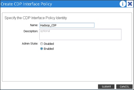
3. Right Click on CDP Interface and select “Create CDP Interface Policy.”

4. In the Create CDP Interface Policy dialogue box, enter Hadoop_CDP as the policy name, set Admin State to Enabled and click Submit.
Creating LLDP Policy group
5. On the menu bar, choose FABRIC > ACCESS POLICIES.
6. In the Navigation pane, expand the Interface Policies and expand the Policies again.
7. Right Click on LLDP Interface and select “Create LLDP Interface Policy.”
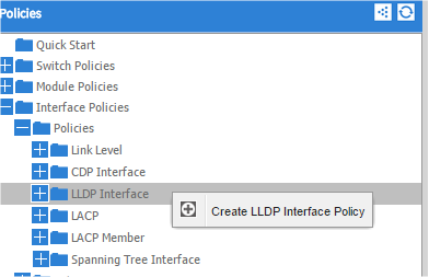
8. In the Create LLDP Interface Policy dialogue box, enter “Hadoop_LLDP” as the policy name, set both the Receive and Transmit State “Disabled” and click submit.
9. This will create the LLDP policy group.
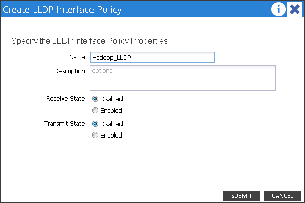
Creating LACP Policy
10. On the menu bar, choose FABRIC > ACCESS POLICIES.
11. In the Navigation pane, expand the Interface Policies and expand the Policies again.
12. Right click on Port Channel Policies and select “Create Port Channel Policy.”
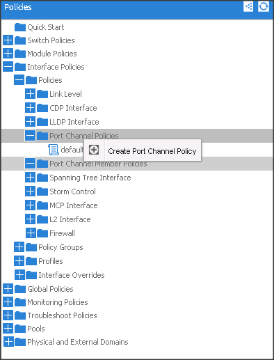
13. In the Create Port Channel Policy window, enter the name Hadoop_LACP. In the mode select the Active radio button and click Submit.
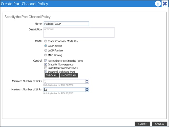
14. Make sure all the policies are created.
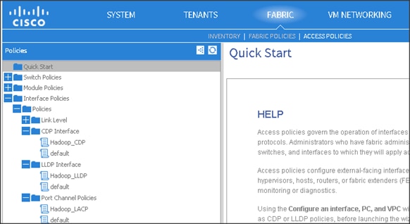
Create a Physical Domain and vlan Pool
1. On the menu bar, choose FABRIC > ACCESS POLICIES.
2. In the Navigation pane, expand the Physical and External Domain and expand the Physical Domain again.
3. Right Click on Physical Domain and select “Create Physical Domain.”
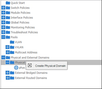
4. In the Create Physical Domain windows, in the Name field enter “Hadoop”
5. In the VLAN Pool drop down list choose Create VLAN Pool.
6. In the Create VLAN Pool windows, in the name field enter Hadoop.
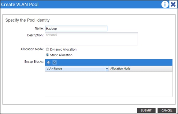
7. In the allocation mode choose Static Allocation.
8. Click “+” in the Encap Blocks area to create a Range of Vlans.
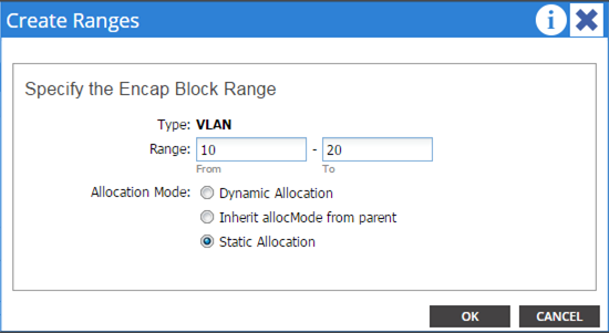
9. In the create Range window, enter vlan id 10 to 20.
10. In the Allocation mode select Static Allocation and click OK.
11. Click Submit in the Create VLAN Pool window.
12. Click Submit in Create Physical Domain window.
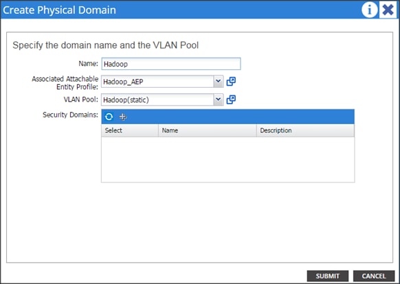
13. This will create a vlan pool, AEP and a Physical Domain.
Creating vPC
1. On the menu bar, choose FABRIC > ACCESS POLICIES.
2. In the quick start windows, click Configure an interface, PC, and VPC to open the configuration wizard.
3. Click the Green “+” button to select the switches to configure the VPCs and perform the following actions:
4. In the Switches drop-down list, check the check boxes for the switches that you want to connect to the Fabric Interconnect. (LEAF_1 & LEAF_2).
5. In the Switch Profile Name field, enter a name for the profile FI_Connected_Leaves and click SAVE.
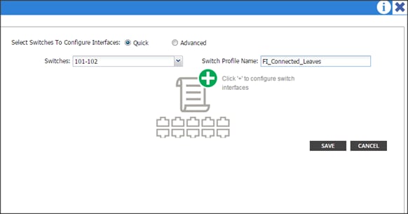
6. Click the + icon to configure the ports.
7. In the Interface Type area, verify the VPC radio button is selected.
8. In the Interfaces field, enter the ports where FI’s are connected (1/1-8)
9. In the Interface Selector Name field, enter the name of the port profile (VPC_1).
10. In the Interface Policy Group field, choose a) Hadoop_LACP as a Port Channel Policy b) Hadoop_CDP as a CDP Policy and c) Hadoop_LLDP as a LLDP Policy.
11. In the attached Device Type drop down list choose Bare Metal.
12. In the Domain select the Choose One radio button and in the Physical Domain drop-down list choose Hadoop and click SAVE.
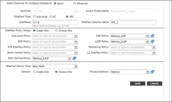
13. Repeat the steps to create VPC ports for all the Fabric Interconnects connected to the ACI fabric. Once all the FI vPC ports are configured, the configured switch interface window should look like the figure below.
Configuring vPC Leaf Pairing
1. In the Configure Interface, PC, and VPC dialog box, click on the “+” on VPC DOMAIN ID.
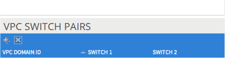
2. In the VPC Domain ID field, enter “110.”
3. In the “Switch A” drop down box, select node “101.”
4. In the “Switch B” drop down box, select node “102” and click Save and Submit.
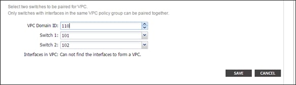
![]() The vPC created here will not come up until the port-channel in Fabric Interconnect is created.
The vPC created here will not come up until the port-channel in Fabric Interconnect is created.
Configuring the Switch Interface for UCSDE
1. On the menu bar, choose FABRIC > ACCESS POLICIES.
2. In the quick start windows, click Configure an interface, PC, and VPC to open the configuration wizard.
3. In the CONFIGURED SWITCH INTERFACE window click 101,102. In the right side click the Green “+” button to configure the interface.
4. Follow the figure below for the configuration parameters.
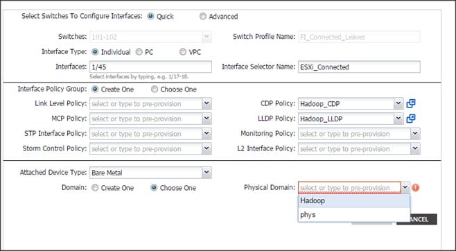
5. In the physical domain choose Hadoop.
6. Click save and click Submit.
Creating Tenants, Private Network, and Bridge Domains
Tenants Overview
· A tenant contains policies that enable qualified users domain-based access control. Qualified users can access privileges such as tenant administration and networking administration.
· A user requires read/write privileges for accessing and configuring policies in a domain. A tenant user can have specific privileges into one or more domains.
· In a multi-tenancy environment, a tenant provides group user access privileges so that resources are isolated from one another (such as for endpoint groups and networking). These privileges also enable different users to manage different tenants.
Creating a Tenant, Private Network, and Bridge Domain Using the GUI
Create and specify a network and a bridge domain for the tenant. The defined bridge domain element subnets reference a corresponding Layer 3 context.
1. On the menu bar, choose TENANTS, and perform the following actions:
a. Click Add Tenant.
b. The Create Tenant dialog box opens.
c. In the Name field, add the tenant name (Production), and click next and click Finish.
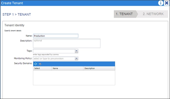
2. Go to TENANTS à Production
3. Expand Tenant Production à Networking, right click on the Private Network and click on Create Private Network.
4. In the Private Network window, in the name field enter Production and click Next.
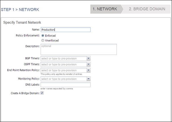
5. In the Specify Bridge Domain for the Network window, in the name field enter Prod_Mgmt.
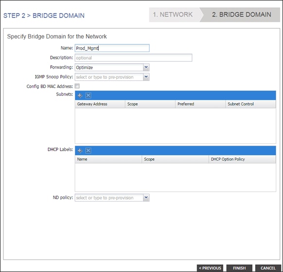
6. Click + in the Subnets and enter 172.16.10.1/24 in the Gateway IP field.
7. In the Scope field, Check the Public Subnet check box and click ok. Only the Mgmt subnet is configured as public, which ACI will advertise to the outside layer 3 network. More details in the section “Configuring outside layer3 network.”
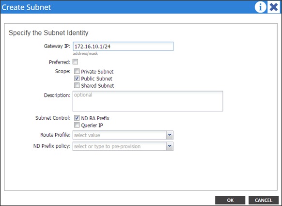
8. Go to TENANTSà Production and right click on Bridge Domain to create 2 more Bridge Domains named Prod_Data1 & Prod_Data2.
9. In the name field enter Prod_Data1.
10. Click + in the Subnets pane and enter 172.16.11.1/24 in the Gateway IP field. Click OK and click Finish.
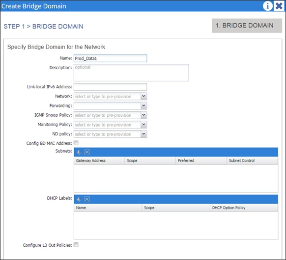
11. Repeat step 9 to create another Bridge Domain.
12. In the name field enter Prod_Data2.
13. Click + in the Subnets and enter 172.16.12.1/24 in the Gateway IP field, click OK and click Finish.
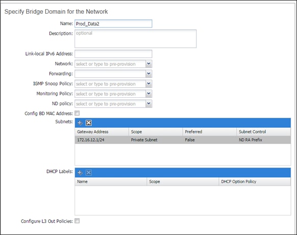
14. Associate all the created Bridge Domains with the private network “Production” created earlier.
15. Select the individual Bridge Domain and in the private network drop down list select Production.
16. In the L2 Unknown Unicast select the Flood radio button and click SUBMIT.
17. Repeat steps 14 to 16 for all the Bridge Domains.
![]()
![]()

18. Confirm that the private network is created and is associated with all the bridge domain.
19. Go to Tenants à Production. Expand the Tenant Production à Networking.
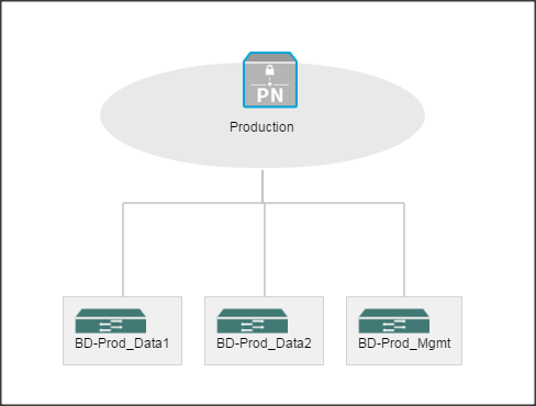
Creating an Application Profile Using the GUI
20. On the menu bar, choose TENANTS à Production. In the Navigation pane, expand the tenant, right-click Application Profiles, and click Create Application Profile.
21. In the Create Application Profile dialog box, in the Name field, add the application profile name (Prod_AP) and click SUBMIT.
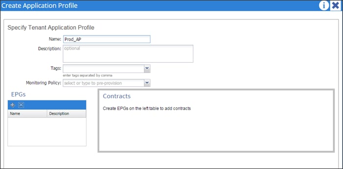
Creating EPGs Using the GUI
1. Expand Tenant Production -> Application Profiles -> Prod_AP, right click on the Application EPGs and select Create Application EPG. In the Create Application EPG dialog box, perform the following actions:
a. In the Name field, add the EPG name (Prod_mgmt).
2. In the Bridge Domain field, choose the bridge domain from the drop-down list (Prod_Mgmt).
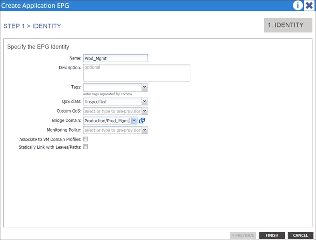
3. Repeat step 1 to create two more EPGs named Prod_Data1 and Prod_Data2. Once all the EPG’s are created it should show similar to the figure below.
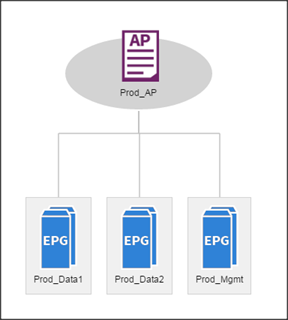
Configuring EPGs
1. Expand Tenant Production à Application Profiles à Prod_AP à Application EPGs à EPG Prod_Mgmt àDomains (VMs and Bare-Metals).
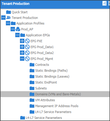
2. Click Actions and click “Add Physical Domain Association.”
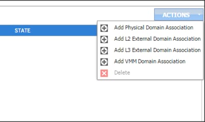
3. In the Add Physical Domain Association dialogue box, in the physical Domain profile droop down list choose Hadoop, select the Deployment Immediacy and Resolution Immediacy as Immediate and click submit.
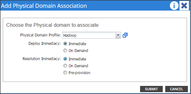
4. Repeat steps 1 through 3 for all the EPG’s.
Creating the Static Bindings for the Leaves and Paths
The static bindings for the leaves are required to associate the physical interfaces with the EPGs.
No traffic flows unless an EPG is deployed on the port. Without VLAN pool deployment using an AEP, a VLAN is not enabled on the leaf port even if an EPG is provisioned. A particular VLAN is provisioned or enabled on the leaf port based on EPG events by statically binding on a leaf port.
1. On the menu bar, choose TENANTS àProduction. In the Navigation pane, expand the tenant > Application Profiles >Prod_AP > Application EPGs > EPG Prod_Mgmt and select Static Bindings (Paths).
![]()
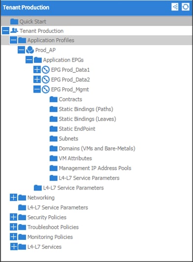
2. Right click on Static Bindings (paths) and select Deploy Static EPG on PC, VPC, or Interface.
3. In the Path Type: select the Virtual Port Channel radio button.
4. From the Path: drop down list select the VPC_1_PolGrp. On Encap field use vlan-10, on Deployment Immediacy select the Immediate radio button, and on Mode select Tagged and click Submit.
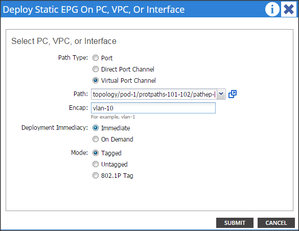
5. Repeat steps 2, 3 & 4 for all the VPC.
6. Similarly, statically bind the ports in other EPGs created using the appropriate VLAN numbers (11 for Prod_Data1 and 12 for Prod_Data2).
7. Once the Static binding for all the EPG is configured properly, verify that the VPC ports created earlier are trunking the appropriate VLANS. This can be verified by the following steps:
a. On the menu bar, choose FABRIC > Access Policies.
8. Expand Pod 1 > LEAF_1 (Node-101) > Interfaces > VPC Interfaces > 1 (This number might be different in different setups). Select any of the Interfaces to view the properties.
Configuring QOS policy for EPG
1. On the menu bar, choose TENANTS àProduction. In the Navigation pane, expand the tenant > Application Profiles >Prod_AP > Application EPGs > EPG Prod_Data1.
2. In the QOS class drop down list select level3
3. Similarly select level2 for EPG Prod_Data2 and level1 for Prod_Mgmt.
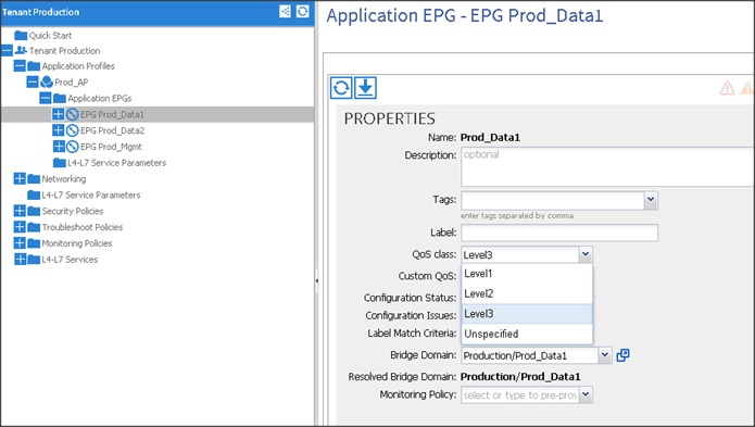
Creating Contracts
Contracts are policies that enable inter-End Point Group (inter-EPG) communication. These policies are the rules that specify communication between application tiers. If no contract is attached to the EPG, inter-EPG communication is disabled by default. No contract is required for intra-EPG communication because intra-EPG communication is always allowed.
1. On the menu bar, choose TENANTS and the tenant name on which you want to operate. In the Navigation pane, expand the Tenant > Security Policies.
a. Right-click Contracts > Create Contract.
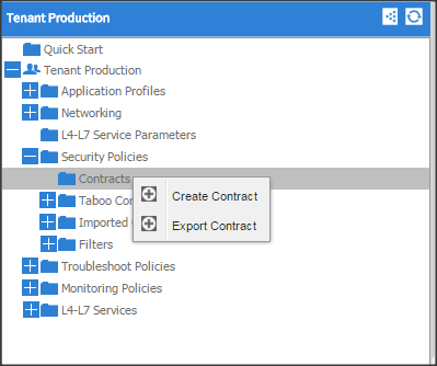
2. In the Create Contract dialog box, in the Name field, enter the contract name Prod_Mgmt.
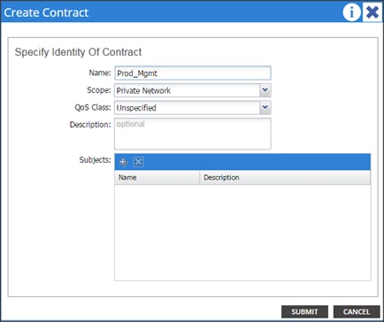
3. Click “+” on the subjects to create a subject for the contract.
4. In the Create Contract Subject window, in the Name filed enter Prod_Mgmt. Click “+” in the Filter Chain, from the drop down list choose Default. Click update and click ok. Click submit on Create Contract window.
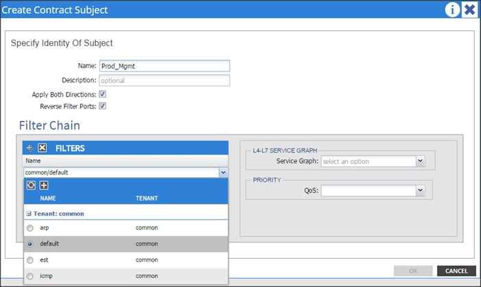
5. On the menu bar, choose TENANTS and the tenant name on which you want to operate. In the Navigation pane, expand the tenant > Application Profiles >Prod_Mgmt > Application EPGs > EPG Prod_Mgmt.
6. Right click on the contract and select Add Provided Contract.

7. In add provided contract dialogue box, from the contract drop-down list choose Production/Prod_Mgmt and click submit.
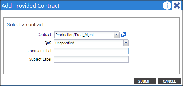
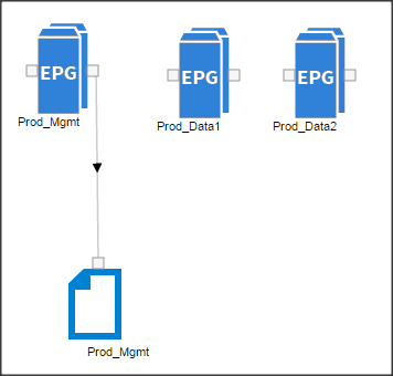
![]() The contract created above will be used to establish communication with the SAP HANA pod.
The contract created above will be used to establish communication with the SAP HANA pod.
Fabric Configuration
This section provides details for configuring a fully redundant, highly available Cisco UCS 6296 fabric configuration.
1. Initial setup of the Fabric Interconnect A and B.
2. Connect to UCS Manager using virtual IP address of using the web browser.
3. Launch UCS Manager.
4. Enable server and uplink ports.
5. Start discovery process.
6. Create pools and polices for service profile template.
7. Create Service Profile template and 64 Service profiles.
8. Associate Service Profiles to servers.
Enabling Uplink Ports
1. Select the Equipment tab on the top left of the window.
2. Select Equipment > Fabric Interconnects > Fabric Interconnect A (primary) > Fixed Module > Ethernet Ports.
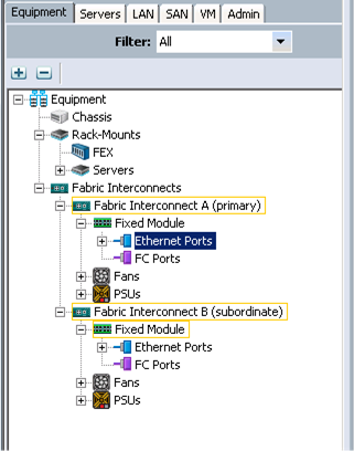
3. On the Right window select all the ports that are connected to the Nexus 9396 leaf switch (16 per FI), right-click them, and select > Configure as uplink Port.
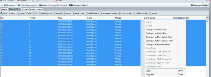
4. Select Equipment > Fabric Interconnects > Fabric Interconnect B (subordinate) > Fixed Module.
5. Expand the Unconfigured Ethernet Ports section.
6. Select all the ports that are connected to the Nexus 9396 leaf switch (16 per FI), right-click them, and select > Configure as uplink Port.
![]() The ports that are configured as uplink port should appear as Network under IF role.
The ports that are configured as uplink port should appear as Network under IF role.
Enabling Server ports
1. Select the Equipment tab on the top left of the window.
2. Select Equipment > Fabric Interconnects > Fabric Interconnect A (primary) > Fixed Module > Ethernet Ports.

3. On the Right window select all the ports that are connected to the UCS C240 server (1 per Server), right-click them, and select > Configure as Server Port.
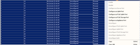
Configuring Port-Channels
1. Select the LAN tab on top left window.
2. Expand the LAN Cloud > Fabric A.
3. On the right window select Create Port Channel.
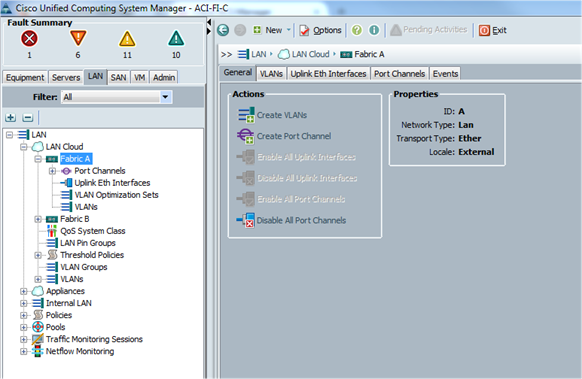
4. On Set Port Channel Name window, perform the following actions:
a. In the ID field, specify the ID “01” as the first port channel
5. In Name field, type P01 for Port-channel01 and click Next.
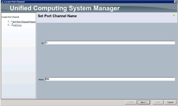
6. In the Add Ports window select all the ports that are connected to the Nexus 9396 Leaf Switch and click >>. This will add all the ports to the port channel created earlier.
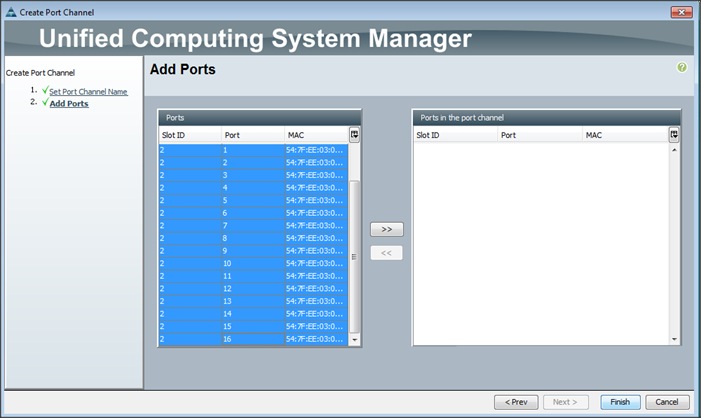
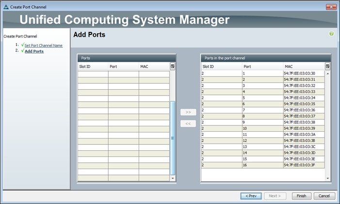
Adding Ports to the Port Channel
1. The configured port channels and vPC can be verified by logging in to the APIC.
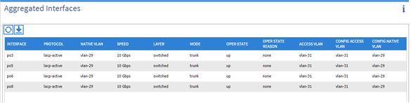
Server Configuration and Cabling for C240M4
The C240 M4 rack server is equipped with Intel Xeon E5-2680 v3 processors, 256 GB of memory, Cisco UCS Virtual Interface Card 1227, Cisco 12-Gbps SAS Modular Raid Controller with 2-GB FBWC, 24 1.2-TB 10K SFF SAS drives, 2 120-GB SATA SSD for Boot.
Figure 1 illustrates the port connectivity between the Fabric Interconnect and Cisco UCS C240 M4 server. Sixteen Cisco UCS C240 M4 servers are used in Master rack configurations.
Figure 19 Fabric Topology for C240 M4
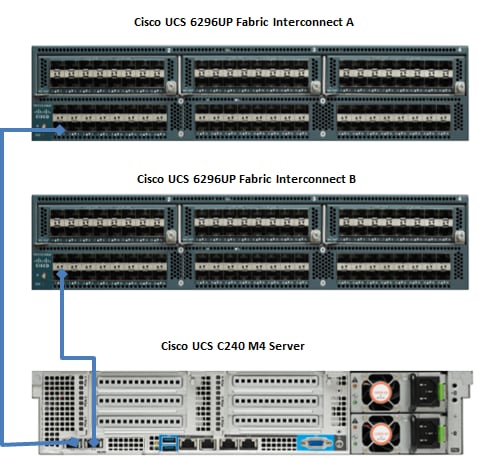
UCS Fabric Configuration
This section provides details for configuring a fully redundant, highly available Cisco UCS 6296 fabric configuration.
Initial setup of the Fabric Interconnect A and B.
This section describes the steps to perform initial setup of the Cisco UCS 6296 Fabric Interconnects A and B.
1. Connect to UCS Manager using virtual IP address of using the web browser.
2. Launch UCS Manager.
3. Enable server, uplink and appliance ports.
4. Start discovery process.
5. Create pools and polices for service profile template.
6. Create Service Profile template and 64 Service profiles.
7. Associate Service Profiles to servers.
Configure Fabric Interconnect A
1. Connect to the console port on the first Cisco UCS 6296 Fabric Interconnect.
2. At the prompt to enter the configuration method, enter console to continue.
3. If asked to either perform a new setup or restore from backup, enter setup to continue.
4. Enter y to continue to set up a new Fabric Interconnect.
5. Enter y to enforce strong passwords.
6. Enter the password for the admin user.
7. Enter the same password again to confirm the password for the admin user.
8. When asked if this fabric interconnect is part of a cluster, answer y to continue.
9. Enter A for the switch fabric.
10. Enter the cluster name for the system name.
11. Enter the Mgmt0 IPv4 address.
12. Enter the Mgmt0 IPv4 netmask.
13. Enter the IPv4 address of the default gateway.
14. Enter the cluster IPv4 address.
15. To configure DNS, answer y.
16. Enter the DNS IPv4 address.
17. Answer y to set up the default domain name.
18. Enter the default domain name.
19. Review the settings that were printed to the console, and if they are correct, answer yes to save the configuration.
20. Wait for the login prompt to make sure the configuration has been saved.
Configure Fabric Interconnect B
1. Connect to the console port on the second Cisco UCS 6296 Fabric Interconnect.
2. When prompted to enter the configuration method, enter console to continue.
3. The installer detects the presence of the partner Fabric Interconnect and adds this fabric interconnect to the cluster. Enter y to continue the installation.
4. Enter the admin password that was configured for the first Fabric Interconnect.
5. Enter the Mgmt0 IPv4 address.
6. Answer yes to save the configuration.
7. Wait for the login prompt to confirm that the configuration has been saved.
![]() For more information on configuring Cisco UCS 6200 Series Fabric Interconnect, see: http://www.cisco.com/c/en/us/td/docs/unified_computing/ucs/sw/gui/config/guide/2-2/b_UCSM_GUI_Configuration_Guide_2_2/configuring_the_fabric_interconnects.html
For more information on configuring Cisco UCS 6200 Series Fabric Interconnect, see: http://www.cisco.com/c/en/us/td/docs/unified_computing/ucs/sw/gui/config/guide/2-2/b_UCSM_GUI_Configuration_Guide_2_2/configuring_the_fabric_interconnects.html
Logging Into Cisco UCS Manager
Follow these steps to login to Cisco UCS Manager.
1. Open a Web browser and navigate to the Cisco UCS 6296 Fabric Interconnect cluster address.
2. Click the Launch link to download the Cisco UCS Manager software.
3. If prompted to accept security certificates, accept as necessary.
4. When prompted, enter admin for the username and enter the administrative password.
5. Click Login to log in to the Cisco UCS Manager.
Upgrading UCSM Software to Version 2.2(5b)
This document assumes the use of UCS 2.2(5b). Refer to Upgrading between Cisco UCS 2.0 Releases to upgrade the Cisco UCS Manager software and UCS 6296 Fabric Interconnect software to version 2.2(5b). Also, make sure the UCS C-Series version 2.2(3d) software bundles is installed on the Fabric Interconnects.
Adding Block of IP Addresses for KVM Access
These steps provide details for creating a block of KVM IP addresses for server access in the Cisco UCS environment.
1. Select the LAN tab at the top of the left window.
2. Select Pools > IpPools > Ip Pool ext-mgmt.
3. Right-click IP Pool ext-mgmt
4. Select Create Block of IPv4 Addresses.
Figure 20 Adding Block of IPv4 Addresses for KVM Access Part 1
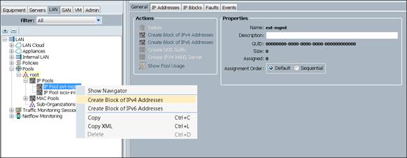
5. Enter the starting IP address of the block and number of IPs needed, as well as the subnet and gateway information.
Figure 21 Adding Block of IPv4 Addresses for KVM Access Part 2
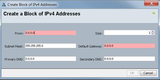
6. Click OK to create the IP block.
7. Click OK in the message box.
Figure 22 Adding Block of IPv4 Addresses for KVM Access Part 3
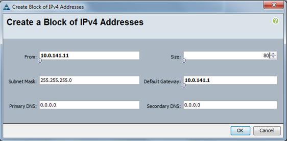
Configuring VLANs
VLANs are configured as in shown in Table 4.
Table 4 VLAN Configurations
| VLAN |
Fabric |
NIC Port |
Function |
Failover |
| default(VLAN1) |
A |
eth0 |
Management, User connectivity |
Fabric Failover to B |
| vlan11_DATA1 |
B |
eth1 |
Hadoop |
Fabric Failover to A |
| vlan12_DATA2 |
A |
eth2 |
SAP HANA DB connectivity |
Fabric Failover to B |
All of the VLANs created need to be trunked to the upstream distribution switch connecting the fabric interconnects. For this deployment default VLAN1 is configured for management access (Installing and configuring OS, clustershell commands, setup NTP, user connectivity, etc) and vlan11_DATA1 is configured for Hadoop Data traffic. vlan12_DATA2 is reserved for the connectivity with SAP HANA system.
![]() All applications talking to Hadoop should be able to reach Hadoop VLAN i.e., access all Hadoop nodes.
All applications talking to Hadoop should be able to reach Hadoop VLAN i.e., access all Hadoop nodes.
![]() We are using default VLAN1 for management traffic.
We are using default VLAN1 for management traffic.
Follow these steps to configure VLANs in the Cisco UCS Manager GUI:
1. Select the LAN tab in the left pane in the UCSM GUI.
2. Select LAN > VLANs.
3. Right-click the VLANs under the root organization.
4. Select Create VLANs to create the VLAN.
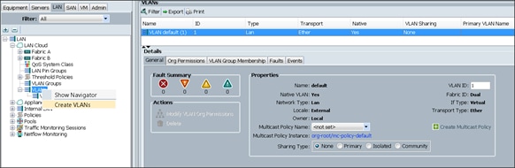
5. Enter vlan11_DATA1 for the VLAN Name.
6. Select Common/Global for the vlan11_DATA1.
7. Enter 11 on VLAN IDs of the Create VLAN IDs.

8. Select the LAN tab in the left pane again
9. Select LAN > VLANs.
10. Right-click the VLANs under the root organization.
11. Select Create VLANs to create the VLAN.
12. Enter vlan12_DATA2 for the VLAN Name.
13. Select Common/Global for the vlan12_DATA2.
14. Enter 12 on VLAN IDs of the Create VLAN IDs.
15. Click Ok and then, click Finish.
16. Click Ok and then, click Finish.
17. Click Ok in the success message box.
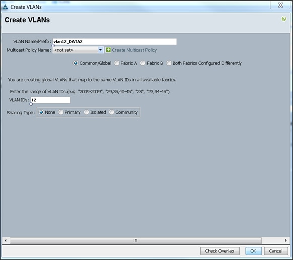
Final list of VLAN created
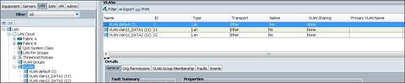
Creating Pools for Service Profile Templates
Creating an Organization
Organizations are used as a means to arrange and restrict access to various groups within the IT organization, thereby enabling multi-tenancy of the compute resources. This document does not assume the use of Organizations; however, the necessary steps are provided for future reference.
Follow these steps to configure an organization within the Cisco UCS Manager GUI:
1. Click New on the top left corner in the right pane in the UCS Manager GUI.
2. Select Create Organization from the options
3. Enter a name for the organization.
4. (Optional) Enter a description for the organization.
5. Click Ok.
6. Click Ok in the success message box.
Creating MAC Address Pools
Follow these steps to create MAC address pools:
1. Select the LAN tab on the left of the window.
2. Select Pools > root.
3. Right-click MAC Pools under the root organization.
4. Select Create MAC Pool to create the MAC address pool. Enter ucs for the name of the MAC pool.
5. (Optional) Enter a description of the MAC pool.
6. Select Assignment Order Sequential.
7. Click Next.
8. Click Add.
9. Specify a starting MAC address.
10. Specify a size of the MAC address pool, which is sufficient to support the available server resources.
11. Click OK.
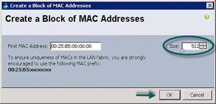
12. Click Finish.
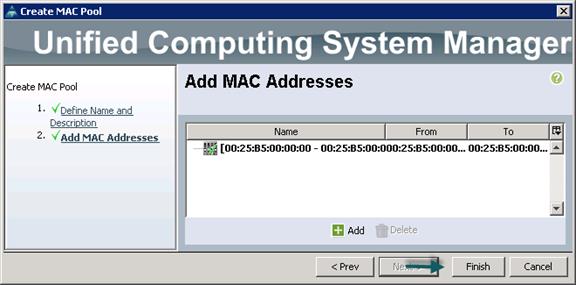
13. When the message box displays, click OK.
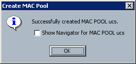
Creating Server Pool
A server pool contains a set of servers. These servers typically share the same characteristics. Those characteristics can be their location in the chassis, or an attribute such as server type, amount of memory, local storage, type of CPU, or local drive configuration. You can manually assign a server to a server pool, or use server pool policies and server pool policy qualifications to automate the assignment
Follow these steps to configure the server pool within the Cisco UCS Manager GUI:
1. Select the Servers tab in the left pane in the UCS Manager GUI.
2. Select Pools > root.
3. Right-click the Server Pools.
4. Select Create Server Pool.
5. Enter your required name (ucs) for the Server Pool in the name text box.
6. (Optional) enter a description for the organization
7. Click Next > to add the servers.
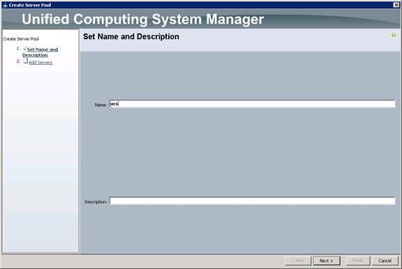
8. Select all the Cisco UCS C240M4SX servers to be added to the server pool you previously created (ucs), then Click >> to add them to the pool.
9. Click Finish.
10. Click Ok and then click Finish.
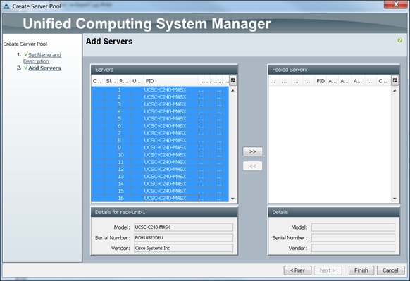
Creating Host Firmware Package Policy
Firmware management policies allow the administrator to select the corresponding packages for a given server configuration. These include adapters, BIOS, board controllers, FC adapters, HBA options, ROM and storage controller properties as applicable.
Follow these steps to create a firmware management policy for a given server configuration using the Cisco UCS Manager GUI:
1. Select the Servers tab in the left pane in the UCS Manager GUI.
2. Select Policies > root.
3. Right-click Host Firmware Packages.
4. Select Create Host Firmware Package.
5. Enter your required Host Firmware package name (ucs).
6. Select Simple radio button to configure the Host Firmware package.
7. Select the appropriate Rack package that you have.
8. Click OK to complete creating the management firmware package.
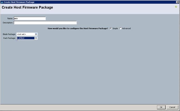
Creating QoS Policies
Follow these steps to create the QoS policy for a given server configuration using the Cisco UCS Manager GUI:
Best Effort Policy
1. Select the LAN tab in the left pane in the UCS Manager GUI.
2. Select Policies > root.
3. Right-click QoS Policies.
4. Select Create QoS Policy.
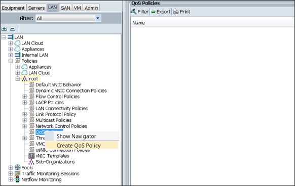
5. Enter BestEffort as the name of the policy.
6. Select BestEffort from the drop down menu.
7. Keep the Burst(Bytes) field as default (10240).
8. Keep the Rate(Kbps) field as default (line-rate).
9. Keep Host Control radio button as default (none).
10. Once the pop-up window appears, click OK to complete the creation of the Policy.

Platinum Policy
1. Select the LAN tab in the left pane in the UCSM GUI.
2. Select Policies > root.
3. Right-click QoS Policies.
4. Select Create QoS Policy.
5. Enter Platinum as the name of the policy.
6. Select Platinum from the drop down menu.
7. Keep the Burst(Bytes) field as default (10240).
8. Keep the Rate(Kbps) field as default (line-rate).
9. Keep Host Control radio button as default (none).
10. Once the pop-up window appears, click OK to complete the creation of the Policy.
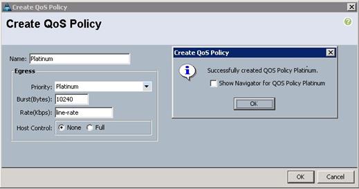
Setting Jumbo Frames
Follow these steps for setting Jumbo frames and enabling QoS:
1. Select the LAN tab in the left pane in the UCSM GUI.
2. Select LAN Cloud > QoS System Class.
3. In the right pane, select the General tab
4. In the Platinum row, enter 9000 for MTU.
5. Check the Enabled Check box next to Platinum.
6. In the Best Effort row, select best-effort for weight.
7. In the Fiber Channel row, select none for weight.
8. Click Save Changes.
9. Click OK.
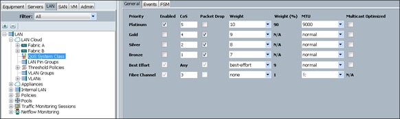
Creating Local Disk Configuration Policy
1. Follow these steps to create local disk configuration in the Cisco UCS Manager GUI:
2. Select the Servers tab on the left pane in the UCS Manager GUI.
3. Go to Policies > root.
4. Right-click Local Disk Config Policies.
5. Select Create Local Disk Configuration Policy.
6. Enter ucs as the local disk configuration policy name.
7. Change the Mode to Any Configuration. check the Protect Configuration box.
8. Keep the FlexFlash State field as default (Disable).
9. Keep the FlexFlash RAID Reporting State field as default (Disable).
10. Click OK to complete the creation of the Local Disk Configuration Policy.
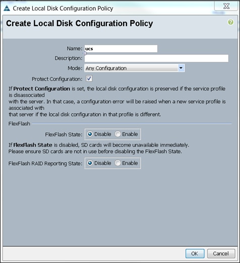
Creating Server BIOS Policy
The BIOS policy feature in Cisco UCS automates the BIOS configuration process. The traditional method of setting the BIOS is done manually and is often error-prone. By creating a BIOS policy and assigning the policy to a server or group of servers, you can enable transparency within the BIOS settings configuration.
![]() BIOS settings can have a significant performance impact, depending on the workload and the applications. The BIOS settings listed in this section is for configurations optimized for best performance which can be adjusted based on the application, performance and energy efficiency requirements.
BIOS settings can have a significant performance impact, depending on the workload and the applications. The BIOS settings listed in this section is for configurations optimized for best performance which can be adjusted based on the application, performance and energy efficiency requirements.
Follow these steps to create a server BIOS policy using the Cisco UCS Manager GUI:
1. Select the Servers tab in the left pane in the UCS Manager GUI.
2. Select Policies > root.
3. Right-click BIOS Policies.
4. Select Create BIOS Policy.
5. Enter your preferred BIOS policy name (ucs).
6. Change the BIOS settings as per the following figures:
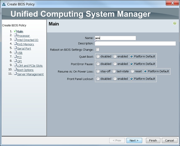
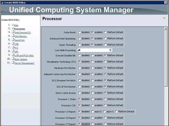
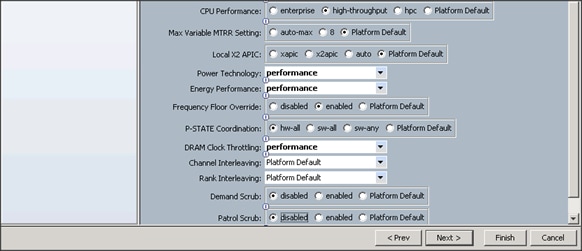
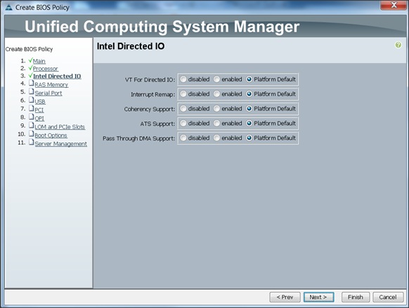
7. Click Finish to complete creating the BIOS policy.
8. Click OK.
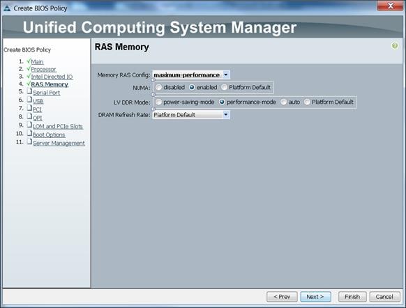
Creating Boot Policy
Follow these steps to create boot policies within the Cisco UCS Manager GUI:
1. Select the Servers tab in the left pane in the UCS Manager GUI.
2. Select Policies > root.
3. Right-click the Boot Policies.
4. Select Create Boot Policy
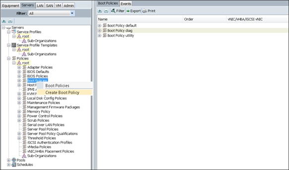
5. Enter ucs as the boot policy name.
6. (Optional) enter a description for the boot policy.
7. Keep the Reboot on Boot Order Change check box unchecked.
8. Keep Enforce vNIC/vHBA/iSCSI Name check box checked.
9. Keep Boot Mode Default (Legacy).
10. Expand Local Devices > Add CD/DVD and select Add Local CD/DVD.
11. Expand Local Devices and select Add Local Disk.
12. Expand vNICs and select Add LAN Boot and enter eth0.
13. Click OK to add the Boot Policy.
14. Click OK.
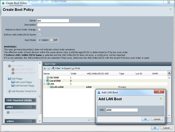
Creating Power Control Policy
Follow these steps to create Power Control policies within the Cisco UCS Manager GUI:
1. Select the Servers tab in the left pane in the UCS Manager GUI.
2. Select Policies > root.
3. Right-click the Power Control Policies.
4. Select Create Power Control Policy
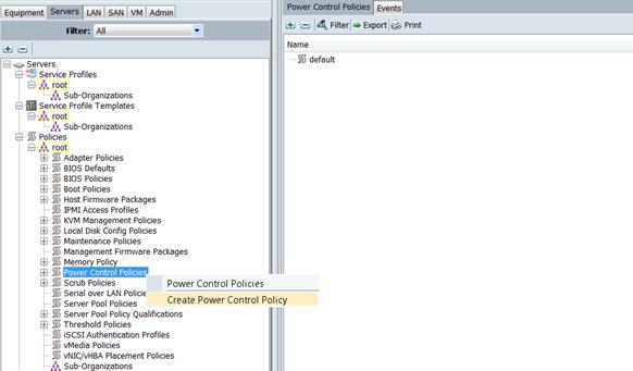
5. Enter ucs as the Power Control policy name.
6. (Optional) enter a description for the boot policy.
7. Select No cap for Power Capping selection.
8. Click OK to the Power Control Policy.
9. Click OK.
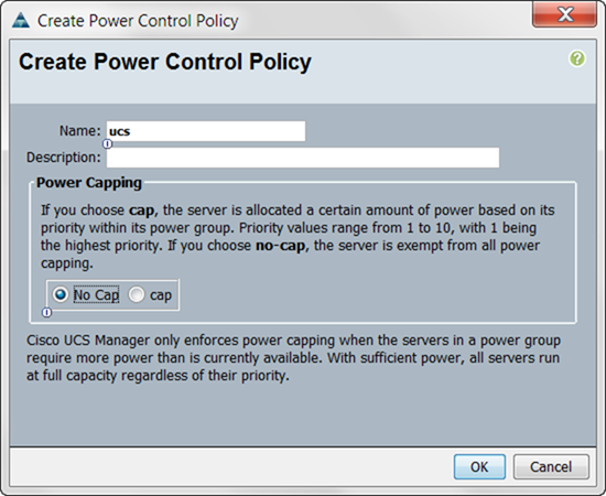
To create a service profile template, follow these steps:
1. Select the Servers tab in the left pane in the UCSM GUI.
2. Right-click Service Profile Templates.
3. Select Create Service Profile Template.
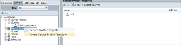
4. The Create Service Profile Template window appears.
These steps below provide a detailed configuration procedure to identify the service profile template:
5. Name the service profile template as ucs. Select the Updating Template radio button.
6. In the UUID section, select Hardware Default as the UUID pool.
7. Click Next to continue to the next section.
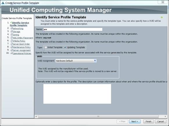
Configuring Network Settings for the Template
1. Keep the Dynamic vNIC Connection Policy field at the default.
2. Select Expert radio button for the option how would you like to configure LAN connectivity?
3. Click Add to add a vNIC to the template.
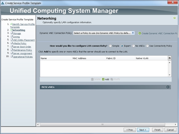
4. The Create vNIC window displays. Name the vNIC as eth0.
5. Select ucs in the Mac Address Assignment pool.
6. Select the Fabric A radio button and check the Enable failover check box for the Fabric ID.
7. Check the default check box for VLANs and select the Native VLAN radio button.
8. Select MTU size as 1500
9. Select adapter policy as Linux
10. Select QoS Policy as BestEffort.
11. Keep the Network Control Policy as Default.
12. Keep the Connection Policies as Dynamic vNIC.
13. Keep the Dynamic vNIC Connection Policy as <not set>.
14. Click Ok.

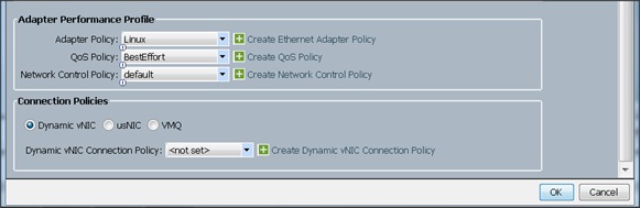
15. Click Add to add a vNIC to the template
16. The Create vNIC window appears. Name the vNIC eth1.
17. Select ucs in the Mac Address Assignment pool.
18. Select Fabric B radio button and check the Enable failover check box for the Fabric ID.
19. Check the vlan11_DATA1 check box for VLANs and select the Native VLAN radio button
20. Select MTU size as 9000
21. Select adapter policy as Linux
22. Select QoS Policy as Platinum.
23. Keep the Network Control Policy as Default.
24. Keep the Connection Policies as Dynamic vNIC.
25. Keep the Dynamic vNIC Connection Policy as <not set>.
26. Click Ok.
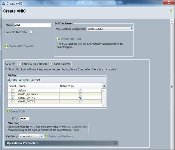
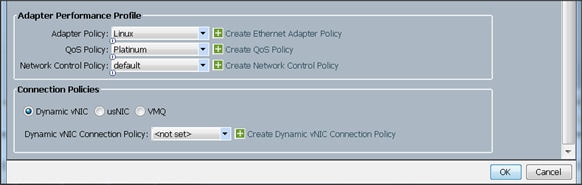
27. Click Add to add a vNIC to the template
28. The Create vNIC window appears. Name the vNIC eth2.
29. Select ucs in the Mac Address Assignment pool.
30. Select Fabric A radio button and check the Enable failover check box for the Fabric ID.
31. Check the vlan12_DATA2 check box for VLANs and select the Native VLAN radio button
32. Select MTU size as 9000
33. Select adapter policy as Linux
34. Select QoS Policy as Platinum.
35. Keep the Network Control Policy as Default.
36. Keep the Connection Policies as Dynamic vNIC.
37. Keep the Dynamic vNIC Connection Policy as <not set>.
38. Click Ok.
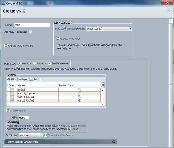
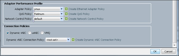
Configuring Storage Policy for the Template
Follow these steps to configure storage policies:
1. Select ucs for the local disk configuration policy.
2. Select the No vHBAs radio button for the option for How would you like to configure SAN connectivity?
3. Click Next to continue to the next section.
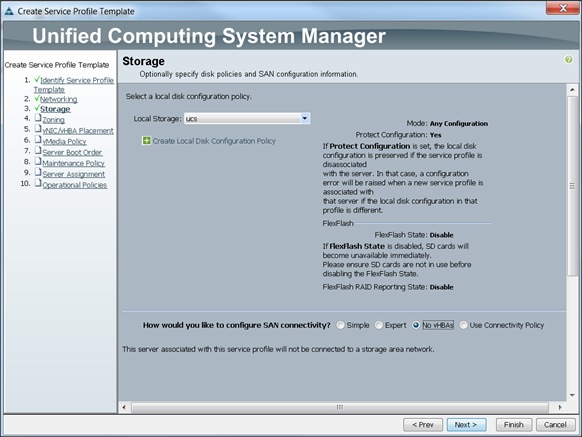
4. Click Next once the zoning window appears to go to the next section.
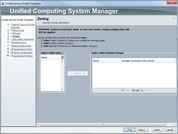
Configuring vNIC/vHBA Placement for the Template
Follow these steps to configure vNIC/vHBA placement policy:
1. Select the Default Placement Policy option for the Select Placement field.
2. Select eth0, eth1 and eth2 assign the vNICs in the following order:
1) eth0
2) eth1
3) eth2
3. Review to make sure that all of the vNICs were assigned in the appropriate order.
4. Click Next to continue to the next section.
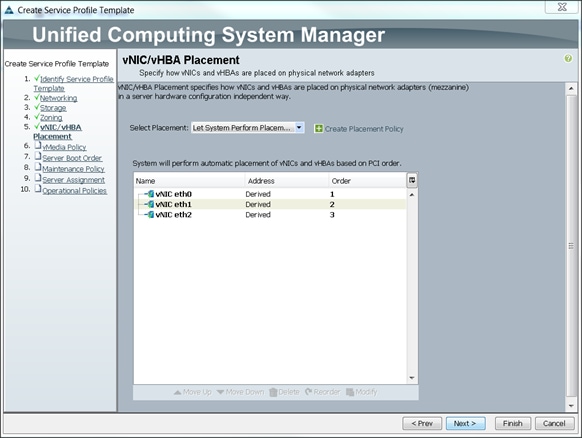
Configuring vMedia Policy for the Template
1. Click Next once the vMedia Policy window appears to go to the next section.
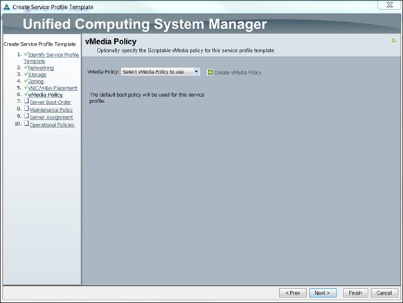
Configuring Server Boot Order for the Template
Follow these steps to set the boot order for servers:
1. Select ucs in the Boot Policy name field.
2. Review to make sure that all of the boot devices were created and identified.
3. Verify that the boot devices are in the correct boot sequence.
4. Click OK.
5. Click Next to continue to the next section.
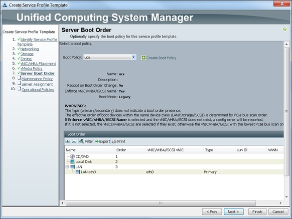
In the Maintenance Policy window, follow these steps to apply the maintenance policy:
6. Keep the Maintenance policy at no policy used by default.
7. Click Next to continue to the next section.
Configuring Server Assignment for the Template
In the Server Assignment window, follow these steps to assign the servers to the pool:
1. Select ucs for the Pool Assignment field.
2. Keep the Server Pool Qualification field at default.
3. Select ucs in Host Firmware Package.
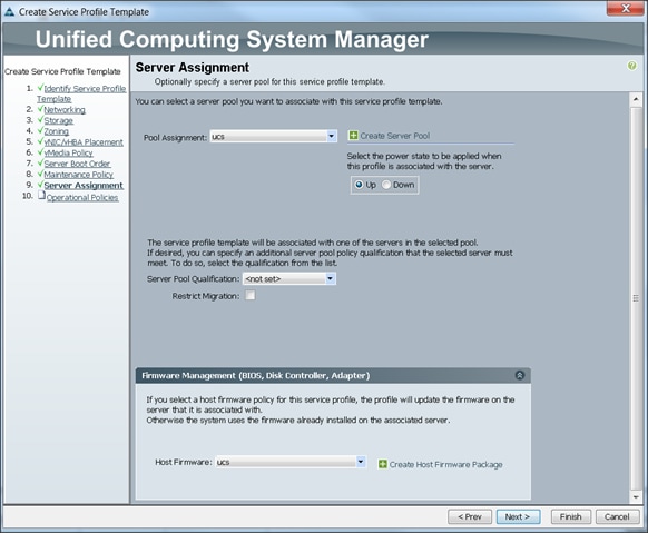
Configuring Operational Policies for the Template
In the Operational Policies Window, follow these steps:
1. Select ucs in the BIOS Policy field.
2. Select ucs in the Power Control Policy field.
3. Click Finish to create the Service Profile template.
4. Click OK in the pop-up window to proceed.
The following section provides detailed procedures for installing Red Hat Enterprise Linux 6.5 using Software RAID (OS based Mirroring) on Cisco UCS C240 M4 servers.
There are multiple methods to install Red Hat Linux operating system. The installation procedure described in this deployment guide uses KVM console and virtual media from Cisco UCS Manager.
![]() Note: This requires RHEL 6.5 DVD/ISO for the installation
Note: This requires RHEL 6.5 DVD/ISO for the installation
1. Log in to the Cisco UCS 6296 Fabric Interconnect and launch the Cisco UCS Manager application.
2. Select the Equipment tab.
3. In the navigation pane expand Rack-Mounts and then Servers.
4. Right click on the server and select KVM Console.
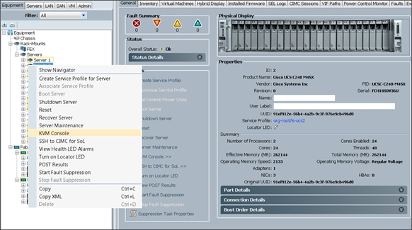
5. In the KVM window, select the Virtual Media tab.
6. Click the Activate Virtual Devices found in Virtual Media tab
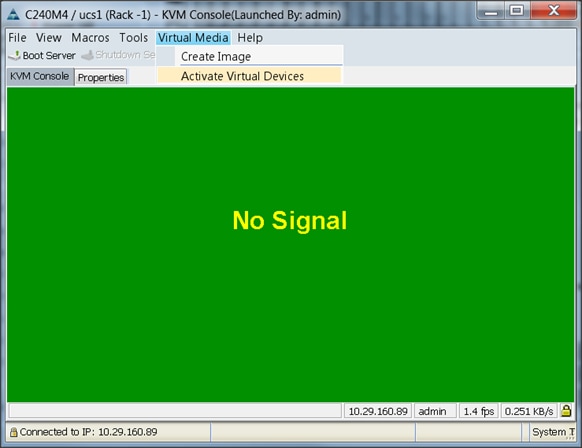
7. In the KVM window, select the Virtual Media tab and Click the Map CD/DVD.
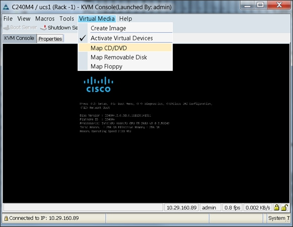
8. Browse to the Red Hat Enterprise Linux Server 6.6 installer ISO image file.
![]() Note: The Red Hat Enterprise Linux 6.6 DVD is assumed to be on the client machine.
Note: The Red Hat Enterprise Linux 6.6 DVD is assumed to be on the client machine.
9. Click Open to add the image to the list of virtual media.
10. Click on Map Device button to complete.

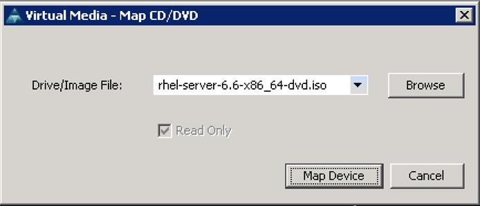
11. In the KVM window, select the KVM tab to monitor during boot.
12. In the KVM window, select the Macros > Static Macros > Ctrl-Alt-Del button in the upper left corner.
13. Click OK.
14. Click OK to reboot the system.
15. On reboot, the machine detects the presence of the Red Hat Enterprise Linux Server 6.6 install media.
16. Select the Install or Upgrade an Existing System.
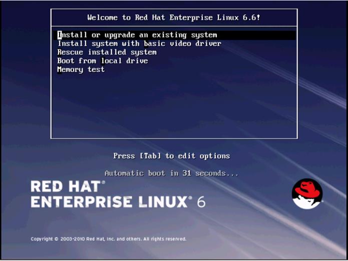
17. Skip the Media test and start the installation.
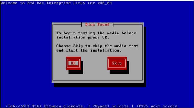
18. Click Next

19. Select language of installation and Click Next.
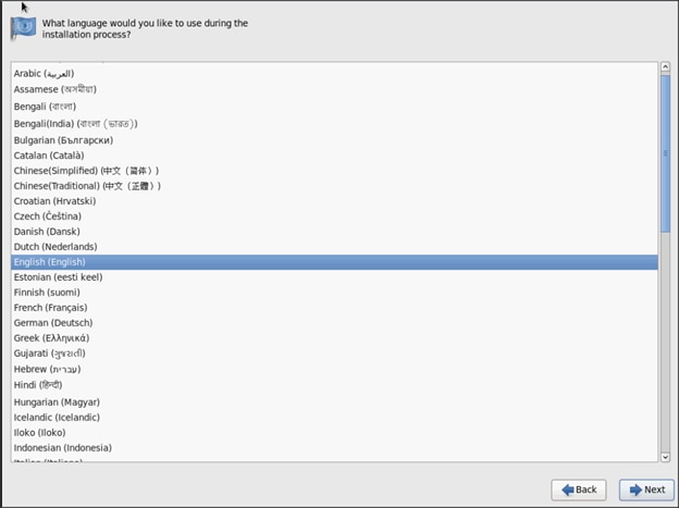
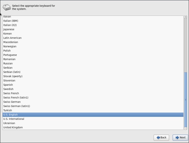
20. Select Basic Storage Devices and Click Next.
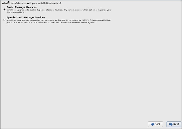
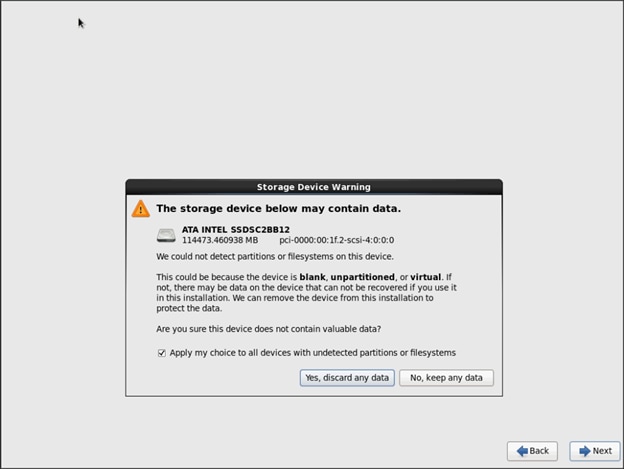
21. Provide Hostname and configure Networking for the Host
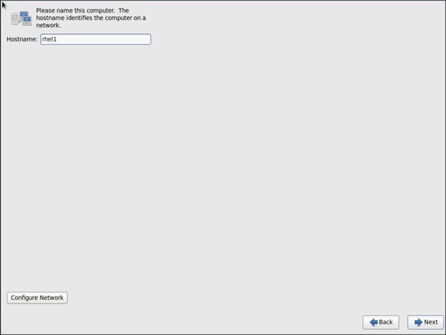
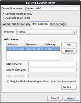
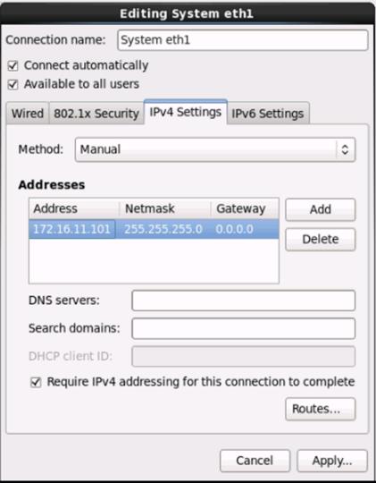
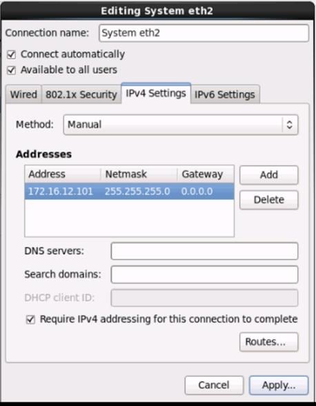
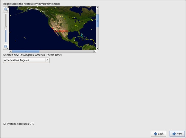

22. Choose Create custom layout for Installation type
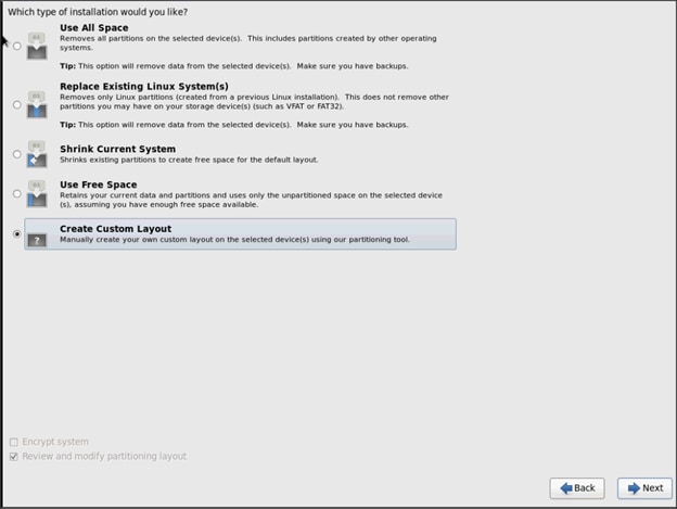
The following steps can be used to create two software RAID 1 partitions for boot and / (root) partitions.
1. Choose free volume and click on Create and choose RAID Partition
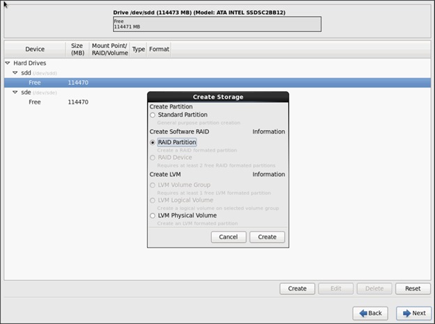
2. Choose “Software RAID” for File system Type and set size for Boot volume
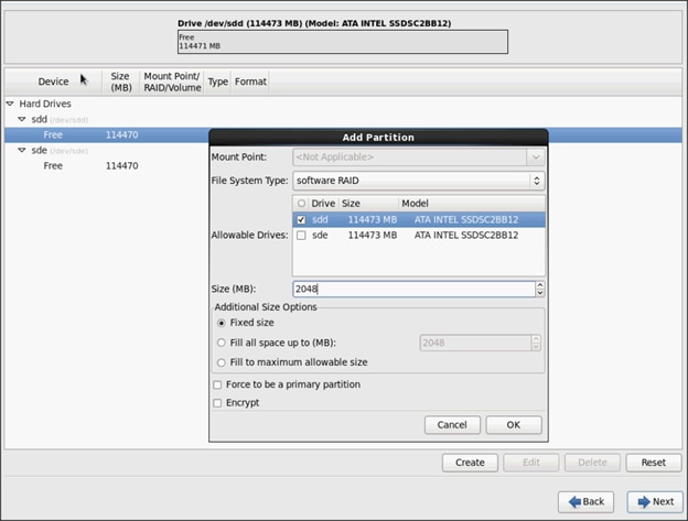
3. Similarly do for the other free volume
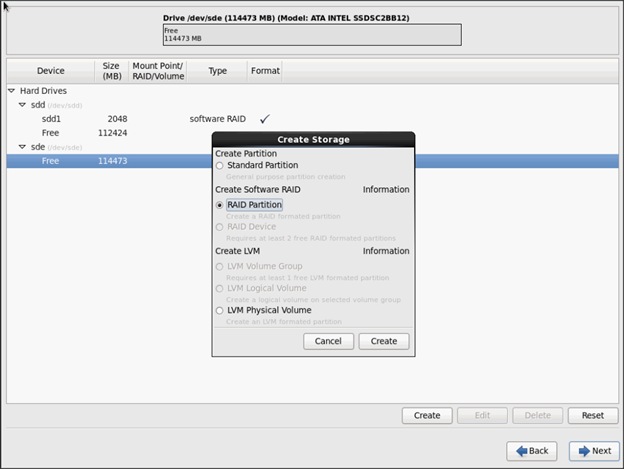
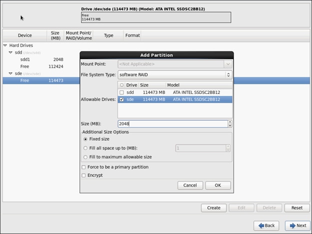
4. Now similarly create RAID partitions for root (/) partition on both the devices and use rest of the available space.
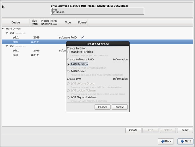
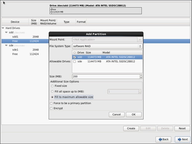
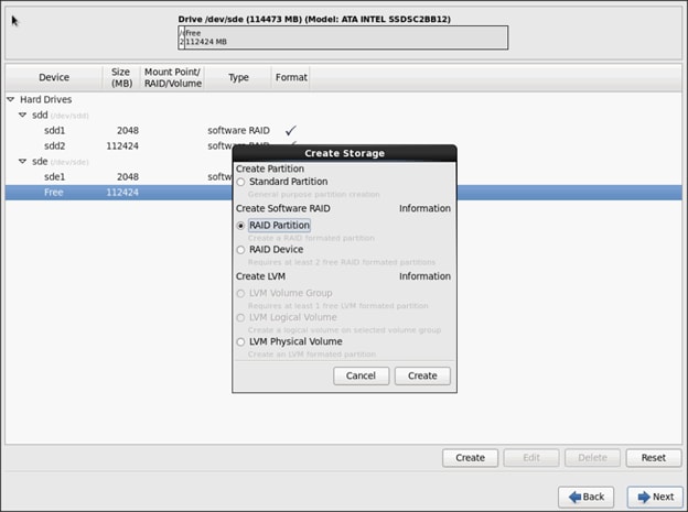
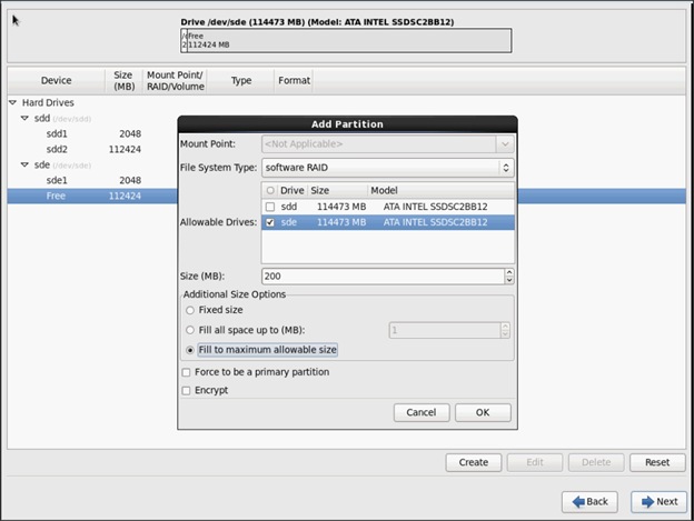
5. The above steps created 2 boot and 2 root (/) partitions. Following steps will RAID1 Devices
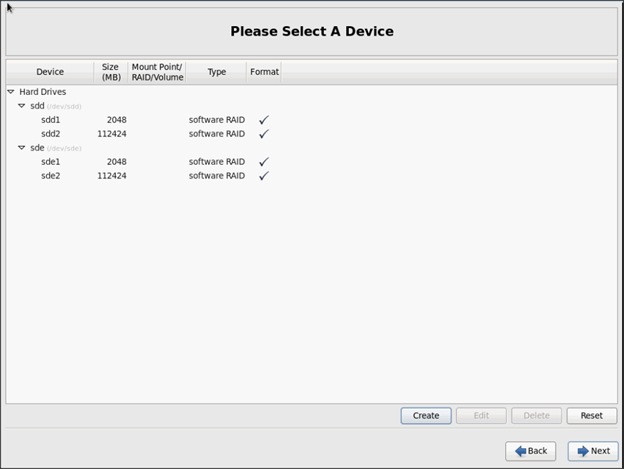
6. Choose one of the boot partitions and click on Create > RAID Device
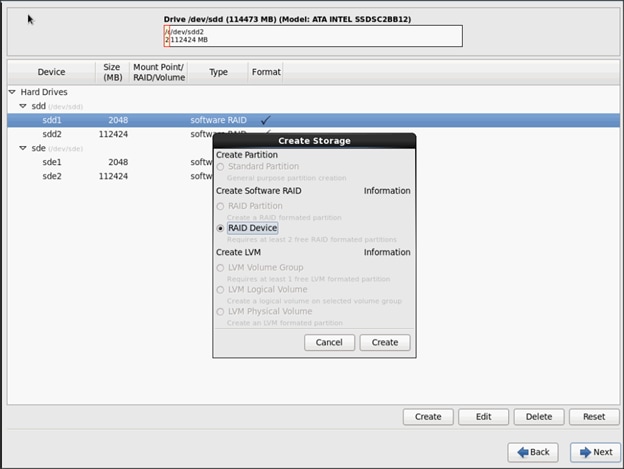
7. Choose this as /boot (boot device) and in RAID members, choose all the boot partitions created above in order to create a software RAID 1 for boot
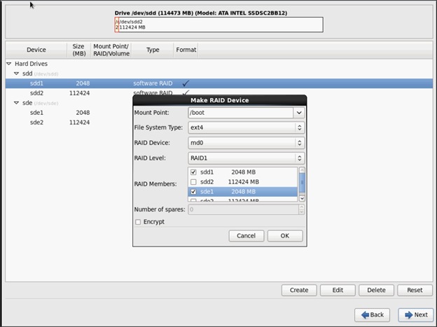
8. Similarly repeat for / partitions created above choosing both members with mount point as “/”.
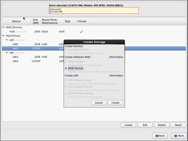
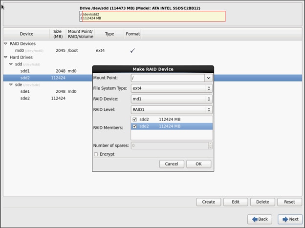
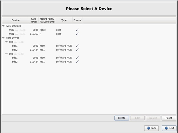
9. Click on Next.
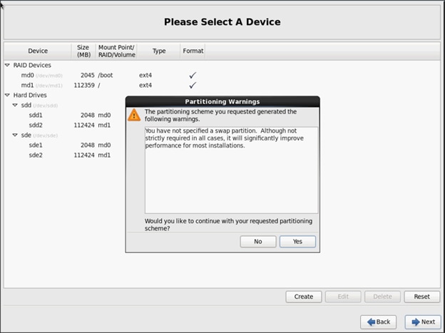
![]() Note: Swap partition can be created using the similar steps, however, since these systems are high in memory, this step is skipped (click Yes).
Note: Swap partition can be created using the similar steps, however, since these systems are high in memory, this step is skipped (click Yes).
10. Click Next, and Format.
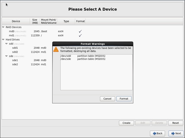
11. Select default settings and click Next.
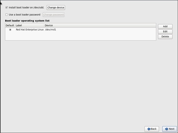
12. Continue with RHEL Installation as shown below.
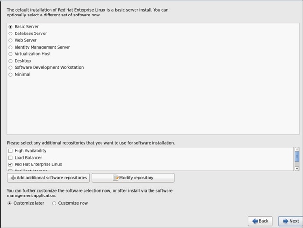
13. Once the installation is complete reboot the system.
Repeat the steps 1 to 34 to install Red Hat Enterprise Linux 6.6 on Servers 2 through 32.
![]() Note: The OS installation and configuration of the nodes that is mentioned above can be automated through PXE boot or third party tools.
Note: The OS installation and configuration of the nodes that is mentioned above can be automated through PXE boot or third party tools.
The hostnames and their corresponding IP addresses are shown in Table 6.
Table 5 Hostnames and IP Addresses
| Hostname |
eth0 |
eth1 |
eth2 |
| rhel1 |
172.16.10.101 |
172.16.11.101 |
172.16.12.101 |
| rhel2 |
172.16.10.102 |
172.16.11.102 |
172.16.12.102 |
| rhel3 |
172.16.10.103 |
172.16.11.103 |
172.16.12.103 |
| rhel4 |
172.16.10.104 |
172.16.11.104 |
172.16.12.104 |
| rhel5 |
172.16.10.105 |
172.16.11.105 |
172.16.12.105 |
| rhel6 |
172.16.10.106 |
172.16.11.106 |
172.16.12.106 |
| rhel7 |
172.16.10.107 |
172.16.11.107 |
172.16.12.107 |
| rhel8 |
172.16.10.108 |
172.16.11.108 |
172.16.12.108 |
| rhel9 |
172.16.10.109 |
172.16.11.109 |
172.16.12.109 |
| rhel10 |
172.16.10.110 |
172.16.11.110 |
172.16.12.110 |
| rhel11 |
172.16.10.111 |
172.16.11.111 |
172.16.12.111 |
| rhel12 |
172.16.10.112 |
172.16.11.112 |
172.16.12.112 |
| rhel13 |
172.16.10.113 |
172.16.11.113 |
172.16.12.113 |
| rhel14 |
172.16.10.114 |
172.16.11.114 |
172.16.12.114 |
| rhel15 |
172.16.10.115 |
172.16.11.115 |
172.16.12.115 |
| rhel16 |
172.16.10.116 |
172.16.11.116 |
172.16.12.116 |
| … |
… |
… |
… |
| rhel32 |
172.16.10.132 |
172.16.11.132 |
172.16.12.132 |
Post OS Install Configuration
Choose one of the nodes of the cluster or a separate node as Admin Node for management such as HDP installation, cluster parallel shell, creating a local Red Hat repo and others. In this document, we use rhel1 for this suppose.
Setting Up Password-less Login
To manage all of the clusters nodes from the admin node we need to setup password-less login. It assists in automating common tasks with clustershell (clush, a cluster wide parallel shell), and shell-scripts without having to use passwords.
Once Red Hat Linux is installed across all the nodes in the cluster, follow the steps below in order to enable password-less login across all the nodes.
1. Login to the Admin Node (rhel1).
ssh 172.16.10.101
2. Run the ssh-keygen command to create both public and private keys on the admin node.
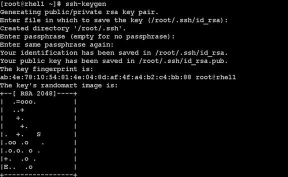
3. Then run the following command from the admin node to copy the public key id_rsa.pub to all the nodes of the cluster. ssh-copy-id appends the keys to the remote-host’s .ssh/authorized_key.
for IP in {101..132}; do echo -n "$IP -> "; ssh-copy-id -i ~/.ssh/id_rsa.pub 172.16.11.$IP; done
4. Enter yes for Are you sure you want to continue connecting (yes/no)?
5. Enter the password of the remote host.
Configuring /etc/hosts
Setup /etc/hosts on the Admin node and other nodes as follows; this is a pre-configuration to setup DNS as shown in the further section.
Follow the steps below to create the host file across all the nodes in the cluster:
1. Populate the host file with IP addresses and corresponding hostnames on the Admin node (rhel1) and other nodes as follows:
On Admin Node (rhel1)
vi /etc/hosts
127.0.0.1 localhost localhost.localdomain localhost4 \ localhost4.localdomain4
::1 localhost localhost.localdomain localhost6 \ localhost6.localdomain6
172.16.11.101 rhel1
172.16.11.102 rhel2
172.16.11.103 rhel3
172.16.11.104 rhel4
172.16.11.105 rhel5
172.16.11.106 rhel6
172.16.11.107 rhel7
172.16.11.108 rhel8
172.16.11.109 rhel9
172.16.11.110 rhel10
172.16.11.111 rhel11
172.16.11.112 rhel12
172.16.11.113 rhel13
172.16.11.114 rhel14
172.16.11.115 rhel15
172.16.11.116 rhel16
...
172.16.11.132 rhel32
Setup ClusterShell
ClusterShell (or clush) is cluster wide shell to run commands on several hosts in parallel.
From the system connected to the Internet download Cluster shell (clush) and install it on rhel1. Cluster shell is available from EPEL (Extra Packages for Enterprise Linux) repository.
wget http://dl.fedoraproject.org/pub/epel/6/x86_64/clustershell-1.6-1.el6.noarch.rpm
scp clustershell-1.6-1.el6.noarch.rpm rhel1:/root/
2. Login to rhel1 and install cluster shell.
yum –y install clustershell-1.6-1.el6.noarch.rpm
3. Edit /etc/clustershell/groups file to include hostnames for all the nodes of the cluster. These set of hosts are taken when running clush with ‘-a’ option.
For 68 node cluster as in our CVD, set groups file as follows,
vi /etc/clustershell/groups
all: rhel[1-32]

![]() Note: For more information and documentation on ClusterShell, visit https://github.com/cea-hpc/clustershell/wiki/UserAndProgrammingGuide
Note: For more information and documentation on ClusterShell, visit https://github.com/cea-hpc/clustershell/wiki/UserAndProgrammingGuide
![]() NOTE: clustershell will not work if not ssh to the machine earlier (as it requires to be in known_hosts file), for instance, as in the case below for rhel<host>.
NOTE: clustershell will not work if not ssh to the machine earlier (as it requires to be in known_hosts file), for instance, as in the case below for rhel<host>.
Creating Red Hat Enterprise Linux (RHEL) 6.6 Local Repo
To create a repository using RHEL DVD or ISO on the admin node (in this deployment rhel1 is used for this purpose), create a directory with all the required RPMs, run the createrepo command and then publish the resulting repository.
1. Log on to rhel1. Create a directory that would contain the repository.
mkdir -p /var/www/html/rhelrepo
2. Copy the contents of the Red Hat DVD to /var/www/html/rhelrepo.
3. Alternatively, if you have access to a Red Hat ISO Image, Copy the ISO file to rhel1.
scp rhel-server-6.6-x86_64-dvd.iso rhel1:/tmp
Have the Red Hat ISO file located in your present working directory.
mkdir -p /mnt/rheliso
mount -t iso9660 -o loop /tmp/rhel-server-6.6-x86_64-dvd.iso /mnt/rheliso/
4. Next, copy the contents of the ISO to the /var/www/html/rhelrepo directory.
cp -r /mnt/rheliso/* /var/www/html/rhelrepo

5. Now on rhel1 create a “.repo” file to enable the use of the yum command.
vi /var/www/html/rhelrepo/rheliso.repo
[rhel6.6]
name=Red Hat Enterprise Linux 6.6
baseurl=http://172.16.10.101/rhelrepo
gpgcheck=0
enabled=
6. Now copy rheliso.repo file from /var/www/html/rhelrepo to /etc/yum.repos.d on rhel1.
cp /var/www/html/rhelrepo/rheliso.repo /etc/yum.repos.d/
![]() Note: Based on this repo file yum requires httpd to be running on rhel1 for other nodes to access the repository.
Note: Based on this repo file yum requires httpd to be running on rhel1 for other nodes to access the repository.
7. Copy the rheliso.repo to all the nodes of the cluster.
clush -a -b -c /etc/yum.repos.d/rheliso.repo --dest=/etc/yum.repos.d/
![]()
8. To make use of repository files on rhel1 without httpd, edit the baseurl of repo file /etc/yum.repos.d/rheliso.repo to point repository location in the file system.
![]() Note: This step is needed to install software on Admin Node (rhel1) using the repo (such as httpd, createrepo, etc)
Note: This step is needed to install software on Admin Node (rhel1) using the repo (such as httpd, createrepo, etc)
vi /etc/yum.repos.d/rheliso.repo
[rhel6.6]
name=Red Hat Enterprise Linux 6.6
baseurl=file:///var/www/html/rhelrepo
gpgcheck=0
enabled=1
9. Creating the Red Hat Repository Database.
10. Install the createrepo package on admin node (rhel1). Use it to regenerate the repository database(s) for the local copy of the RHEL DVD contents.
yum -y install createrepo
11. Run createrepo on the RHEL repository to create the repo database on admin node.
cd /var/www/html/rhelrepo
createrepo
12. Finally, purge the yum caches after httpd is installed (steps in section “Install Httpd”).
Configuring DNS
This section details setting up DNS using dnsmasq as an example based on the /etc/hosts configuration setup in the earlier section.
Follow the steps below to create the host file across all the nodes in the cluster:
1. Disable Network manager on all nodes,
clush -a -b service NetworkManager stop
clush -a -b chkconfig NetworkManager off
2. Update /etc/resolv.conf file to point to Admin Node:
vi /etc/resolv.conf
nameserver 172.16.11.101
![]() Note: This step is needed if setting up dnsmasq on Admin node. Else this file should be updated with the correct nameserver
Note: This step is needed if setting up dnsmasq on Admin node. Else this file should be updated with the correct nameserver
3. Install and Start dnsmasq on Admin node:
yum -y install dnsmasq
service dnsmasq start
chkconfig dnsmasq on
4. Deploy /etc/resolv.conf from the admin node (rhel1) to all the nodes via the following clush command:
clush -a -B -c /etc/resolv.conf
![]() Note: A clush copy without -–dest copies to the same directory location as the source-file directory
Note: A clush copy without -–dest copies to the same directory location as the source-file directory
5. Ensure DNS is working fine by running the following command on Admin node and any data-node
[root@rhel2 ~]# nslookup rhel1
Server: 172.16.11.101
Address: 172.16.11.101#53
Name: rhel1
Address: 172.16.11.101 ç
Installing httpd
Setting up RHEL repo on the admin node requires httpd. This section describes the process of setting up one
1. Install httpd on the admin node to host repositories.
The Red Hat repository is hosted using HTTP on the admin node, this machine is accessible by all the hosts in the cluster.
yum –y install httpd
2. Add ServerName and make the necessary changes to the server configuration file.
vi /etc/httpd/conf/httpd.conf
ServerName 172.16.10.101:80
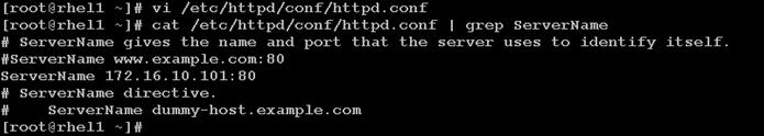
3. Start httpd
service httpd start
chkconfig httpd on
4. Purge the yum caches after httpd is installed (step followed from section Setup Red Hat Repo)
clush -a -B yum clean all
clush –a -B yum repolist
![]() Note: While suggested configuration is to disable SELinux as shown below, if for any reason SELinux needs to be enabled on the cluster, then ensure to run the following to make sure that the httpd is able to read the Yum repofiles
Note: While suggested configuration is to disable SELinux as shown below, if for any reason SELinux needs to be enabled on the cluster, then ensure to run the following to make sure that the httpd is able to read the Yum repofiles
chcon -R -t httpd_sys_content_t /var/www/html/
Upgrading Cisco Network Driver for VIC1227
The latest Cisco Network driver is required for performance and updates. The latest drivers can be downloaded from the link below:
In the ISO image, the required driver kmod-enic-2.1.1.66-rhel6u5.el6.x86_64.rpm can be located at \Linux\Network\Cisco\12x5x\RHEL\RHEL6.5
1. From a node connected to the Internet, download, extract and transfer kmod-enic-2.1.1.66-rhel6u5.el6.x86_64.rpm to rhel1 (admin node).
2. Install the rpm on all nodes of the cluster using the following clush commands. For this example the rpm is assumed to be in present working directory of rhel1.
[root@rhel1 ~]# clush -a -b -c kmod-enic-2.1.1.66-rhel6u5.el6.x86_64.rpm
[root@rhel1 ~]# clush -a -b "rpm -ivh kmod-enic-2.1.1.66-rhel6u5.el6.x86_64.rpm "
Ensure that the above installed version of kmod-enic driver is being used on all nodes by running the command “modinfo enic” on all nodes
[root@rhel1 ~]# clush -a -B "modinfo enic | head -5"
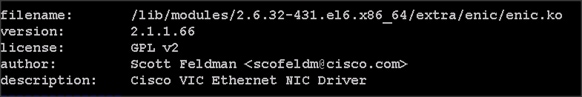
Installing xfsprogs
From the admin node rhel1 run the command below to Install xfsprogs on all the nodes for xfs filesystem.
clush -a -B yum -y install xfsprogs
![]()
Setting up JAVA
HDP 2.2 requires JAVA 7, download jdk-7u80-linux-x64.rpm from oracle.com (http://www.oracle.com/technetwork/java/javase/downloads/jdk7-downloads-1880260.html) to admin node (rhel1).
Create the following files java-set-alternatives.sh and java-home.sh on admin node (rhel1)
vi java-set-alternatives.sh
#!/bin/bash
for item in java javac javaws jar jps javah javap jcontrol jconsole jdb; do
rm -f /var/lib/alternatives/$item
alternatives --install /usr/bin/$item $item /usr/java/jdk1.7.0_80/bin/$item 9
alternatives --set $item /usr/java/jdk1.7.0_80/bin/$item
done
vi java-home.sh
export JAVA_HOME=/usr/java/jdk1.7.0_80
Download and copy the JDK 7 archive the /tmp directory of admin node (rhel1). Run the following commands on admin node (rhel1) to install and setup java on all nodes.
1. Copying JDK rpm to all nodes
clush -b -a -c /tmp/jdk-7u80-linux-x64.rpm --dest=/tmp/
2. Make the two java scripts created above executable
chmod 755 ./java-set-alternatives.sh ./java-home.sh
3. Copying java-set-alternatives.sh to all nodes
clush -b -a -c ./java-set-alternatives.sh --dest=/tmp/
4. Extract and Install JDK on all nodes
clush -a -b rpm -ivh /tmp/jdk-7u80-linux-x64.rpm
5. Setup Java Alternatives
clush -b -a ./java-set-alternatives.sh
6. Ensure correct java is setup on all nodes (should point to newly installed java path)
clush -b -a "alternatives --display java | head -2"
7. Setup JAVA_HOME on all nodes
clush -b -a -c ./java-home.sh --dest=/etc/profile.d
8. Display JAVA_HOME on all nodes
clush -a -b "echo \$JAVA_HOME"
9. Display current java -version
Install Openssl
Install Openssl and Openssl-devel version 1.0.1e-30 and above for RHEL6.6. This is a requirement for HDP 2.2 on all nodes. If openssl is already installed (generally the case), use the following command to upgrade openssl
clush -a yum install -y krb5-devel zlib-devel
clush -a -b -c /root/openssl-*
clush -a -b rpm -Uvh openssl-1.0.1e-*.rpm openssl-devel-1.0.1e-*.rpm

(RPMs available at http://mirror.centos.org/centos/6/updates/x86_64/Packages/openssl-1.0.1e-30.el6_6.5.x86_64.rpm and
http://mirror.centos.org/centos/6/updates/x86_64/Packages/openssl-devel-1.0.1e-30.el6_6.5.x86_64.rpm)
![]() This requires krb5-devel and zlib-devel as dependencies. If not installed, install it as follows on the nodes throwing error “yum –y install krb5-devel zlib-devel”
This requires krb5-devel and zlib-devel as dependencies. If not installed, install it as follows on the nodes throwing error “yum –y install krb5-devel zlib-devel”
NTP Configuration
The Network Time Protocol (NTP) is used to synchronize the time of all the nodes within the cluster. The Network Time Protocol daemon (ntpd) sets and maintains the system time of day in synchronism with the timeserver located in the admin node (rhel1). Configuring NTP is critical for any Hadoop Cluster. If server clocks in the cluster drift out of sync, serious problems will occur with HBase and other services.
|
|
Installing an internal NTP server keeps your cluster synchronized even when an outside NTP server is inaccessible. |
1. Configure /etc/ntp.conf on the admin node with the following contents:
vi /etc/ntp.conf
driftfile /var/lib/ntp/drift
restrict 127.0.0.1
restrict -6 ::1
server 127.127.1.0
fudge 127.127.1.0 stratum 10
includefile /etc/ntp/crypto/pw
keys /etc/ntp/keys
2. Create /tmp/ntp.conf on the admin node and copy it to all nodes
vi /tmp/ntp.conf
server 172.16.10.101
driftfile /var/lib/ntp/drift
restrict 127.0.0.1
restrict -6 ::1
includefile /etc/ntp/crypto/pw
keys /etc/ntp/keys
3. Copy /tmp/ntp.conf file from the admin node to /etc of all the nodes by executing the following command in the admin node (rhel1)
clush -w rhel[2-32] -c /tmp/ntp.conf --dest=/etc/
![]() NOTE: The option “-w” above is very important, so that the NTP client configuration file is copied over to all the nodes but the admin node (rhel1) which serves as the NTP server.
NOTE: The option “-w” above is very important, so that the NTP client configuration file is copied over to all the nodes but the admin node (rhel1) which serves as the NTP server.
4. Run the following to syncronize the time and restart NTP daemon on all nodes
clush -a -B "yum install -y ntpdate"
clush -a -b "service ntpd stop"
clush -a -b "ntpdate rhel1"
clush -a -b "service ntpd start"
5. Ensure restart of NTP daemon across reboots
clush -a -b "chkconfig ntpd on"
Enabling Syslog
Syslog must be enabled on each node to preserve logs regarding killed processes or failed jobs. Modern versions such as syslog-ng and rsyslog are possible, making it more difficult to be sure that a syslog daemon is present. One of the following commands should suffice to confirm that the service is properly configured:
clush -B -a rsyslogd -v
clush -B -a service rsyslog status
Setting ulimit
On each node, ulimit -n specifies the number of inodes that can be opened simultaneously. With the default value of 1024, the system appears to be out of disk space and shows no inodes available. This value should be set to 64000 on every node.
Higher values are unlikely to result in an appreciable performance gain.
1. For setting ulimit on Redhat, edit /etc/security/limits.conf on admin node rhel1 and add the following lines:
* soft nofile 64000
* hard nofile 64000
root soft nproc 64000
root hard nproc 64000
hdfs soft nproc 64000
hdfs hard nproc 64000
hadoop soft nproc 64000
hadoop hard nproc 64000
yarn soft nproc 64000
yarn hard nproc 64000
vora soft nproc 64000
vora hard nproc 64000
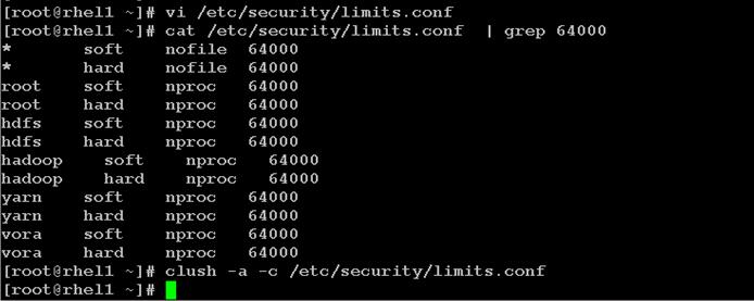
2. Copy the /etc/security/limits.conf file from admin node (rhel1) to all the nodes using the following command.
clush -a -b -c /etc/security/limits.conf --dest=/etc/security/
![]()
3. Edit /etc/security/limits.conf and add the following lines:
4. root soft nofile 64000
root hard nofile 64000
5. Check that the /etc/pam.d/su file contains the following settings:
#%PAM-1.0
auth sufficient pam_rootok.so
#Uncomment the following line to implicitly trust users in the "wheel" group.
#auth sufficient pam_wheel.so trust use_uid
#Uncomment the following line to require a user to be in the "wheel" group.
#auth required pam_wheel.so use_uid
auth include system-auth
account sufficient pam_succeed_if.so uid = 0 use_uid quiet
account include system-auth
password include system-auth
session include system-auth
session optional pam_xauth.so
6. Verify the ulimit setting with the following steps: Run the following command at a command line. The commands should report 64000.
![]() ulimit values are applied on a new shell, running the command on a node on an earlier instance of a shell will show old values
ulimit values are applied on a new shell, running the command on a node on an earlier instance of a shell will show old values
clush -a -B ulimit –n
clush -a -B ulimit –u

Disabling the Linux Firewall
The default Linux firewall settings are far too restrictive for any Hadoop deployment. Since the UCS Big Data deployment will be in its own isolated network, there’s no need to leave the iptables service running.
clush -a -b "service iptables stop"
clush -a -b "chkconfig iptables off"
![]()
Disabling SELinux
SELinux must be disabled during the install procedure and cluster setup. SELinux can be enabled after installation and while the cluster is running.
1. Disable SELinux by editing /etc/selinux/config and changing the SELINUX line to SELINUX=disabled. The following commands will disable SELINUX on all nodes.
clush -a -b "sed -i 's/SELINUX=enforcing/SELINUX=disabled/g' /etc/selinux/config "
clush -a -b "setenforce 0"

![]() The above command may fail if SELinux is already disabled
The above command may fail if SELinux is already disabled
Set TCP Retries
Adjusting the tcp_retries parameter for the system network enables faster detection of failed nodes. Given the advanced networking features of UCS, this is a safe and recommended change (failures observed at the operating system layer are most likely serious rather than transitory). On each node, set the number of TCP retries to 5 can help detect unreachable nodes with less latency.
2. Edit the file /etc/sysctl.conf and on admin node rhel1 and add the following lines:
net.ipv4.tcp_retries2=5
3. Copy the /etc/sysctl.conf file from admin node (rhel1) to all the nodes using the following command.
clush -a -b -c /etc/sysctl.conf --dest=/etc/
4. Load the settings from default sysctl file /etc/sysctl.conf by running
clush -B -a sysctl -p
Disable Swapping
In order to reduce Swapping, run the following on all nodes. Variable vm.swappiness defines how often swap should be used. 0 is No Swapping, 60 default.
clush -a -b " echo 'vm.swappiness=0' >> /etc/sysctl.conf"
1. Load the settings from default sysctl file /etc/sysctl.conf
clush –a –b “sysctl –p”
Disable IPv6 Defaults
1. Disable IPv6 as the addresses used are IPv4.
clush -a -b “echo 'net.ipv6.conf.all.disable_ipv6 = 1' >> /etc/sysctl.conf”
clush -a -b “echo 'net.ipv6.conf.default.disable_ipv6 = 1' >> /etc/sysctl.conf”
clush -a -b “echo 'net.ipv6.conf.lo.disable_ipv6 = 1' >> /etc/sysctl.conf”
2. Load the settings from default sysctl file /etc/sysctl.conf
clush –a –b “sysctl –p”
Disable Transparent Huge Pages
Disabling Transparent Huge Pages (THP) reduces elevated CPU usage caused by THP. From the admin node, run the following commands
clush -a -b "echo never >
/sys/kernel/mm/redhat_transparent_hugepage/enabled"
clush -a -b "echo never >
/sys/kernel/mm/redhat_transparent_hugepage/defrag"
![]() The above command needs to be run for every reboot, hence, copy this command to /etc/rc.local so they are executed automatically for every reboot.
The above command needs to be run for every reboot, hence, copy this command to /etc/rc.local so they are executed automatically for every reboot.
3. On Admin node, run the following commands
rm –f /tmp/thp_disable
echo "echo never > /sys/kernel/mm/redhat_transparent_hugepage/enabled" >> /tmp/thp_disable
echo "echo never > /sys/kernel/mm/redhat_transparent_hugepage/defrag " >> /tmp/thp_disable
4. Copy the file “thp_disable” to each node
clush –a –b –c /tmp/thp_disable
5. Append the content of file thp_disable to /etc/rc.local
clush -a -b “cat /tmp/thp_disable >> /etc/rc.local”
Configuring Data Drives on Name Node
This section describes steps to configure non-OS disk drives as RAID1 using StorCli command as described below. All the drives are going to be part of a single RAID1 volume. This volume can be used for Staging any client data to be loaded to HDFS. This volume won’t be used for HDFS data.
From the website download storcli http://www.lsi.com/downloads/Public/RAID%20Controllers/RAID%20Controllers%20Common%20Files/1.14.12_StorCLI.zip
1. Extract the zip file and copy storcli-1.14.12-1.noarch.rpm from the linux directory.
2. Download storcli and its dependencies and transfer to Admin node.
scp storcli-1.14.12-1.noarch.rpm rhel1:/tmp/
3. Copy storcli rpm to all the nodes using the following commands:
clush -a -b -c /tmp/storcli-1.14.12-1.noarch.rpm --dest=/root/
4. Run the below command to install storcli on all the nodes
clush -a -b rpm -ivh storcli-1.14.12-1.noarch.rpm
5. Run the below command to copy storcli64 to root directory.
cd /opt/MegaRAID/storcli/
cp storcli64 /tmp/

6. Run the following script as root user on NameNode and Secondary NameNode to create the virtual drives.
vi /tmp/raid1.sh
/opt/MegaRAID/storcli/storcli64 -cfgldadd r1[$1:1,$1:2,$1:3,$1:4,$1:5,$1:6,$1:7,$1:8,$1:9,$1:10,$1:11,$1:12,$1:13,$1:14,$1:15,$1:16,$1:17,$1:18,$1:19,$1:20,$1:21,$1:22,$1:23,$1:24] wb ra nocachedbadbbu strpsz1024 -a0
The above script requires enclosure ID as a parameter. Run the following command to get enclousure id.
/opt/MegaRAID/storcli/storcli64 pdlist -a0 | grep Enc | grep -v 252 | awk '{print $4}' | sort | uniq -c | awk '{print $2}'
chmod 755 raid1.sh
7. Run MegaCli script as follows
/tmp/raid1.sh <EnclosureID> obtained by running the command above
WB: Write back
RA: Read Ahead
NoCachedBadBBU: Do not write cache when the BBU is bad.
Strpsz1024: Strip Size of 1024K
![]() The command above will not override any existing configuration. To clear and reconfigure existing configurations refer to Embedded MegaRAID Software Users Guide available at www.lsi.com
The command above will not override any existing configuration. To clear and reconfigure existing configurations refer to Embedded MegaRAID Software Users Guide available at www.lsi.com
Configuring Data Drives on Data Nodes
This section describes steps to configure non-OS disk drives as individual RAID0 volumes using StorCli command as described below. These volumes are going to be used for HDFS Data.
1. Issue the following command from the admin node to create the virtual drives with individual RAID 0 configurations on all the datanodes.
clush –w rhel[3-32] -B /opt/MegaRAID/storcli/storcli64 -cfgeachdskraid0 WB RA direct NoCachedBadBBU strpsz1024 -a0
WB: Write back
RA: Read Ahead
NoCachedBadBBU: Do not write cache when the BBU is bad.
Strpsz1024: Strip Size of 1024K
![]()
![]() The command above will not override existing configurations. To clear and reconfigure existing configurations refer to Embedded MegaRAID Software Users Guide available at www.lsi.com.
The command above will not override existing configurations. To clear and reconfigure existing configurations refer to Embedded MegaRAID Software Users Guide available at www.lsi.com.
Configuring the Filesystem for NameNodes, and Datanodes
The following script will format and mount the available volumes on each node whether it is Namenode, Data node or Archival node. OS boot partition is going to be skipped. All drives are going to be mounted based on their UUID as /data/disk1, /data/disk2, and so on.
1. On the Admin node, create a file containing the following script.
To create partition tables and file systems on the local disks supplied to each of the nodes, run the following script as the root user on each node.
![]() Note: The script assumes there are no partitions already existing on the data volumes. If there are partitions, then they have to be deleted first before running this script. This process is documented in the “Note” section at the end of the section
Note: The script assumes there are no partitions already existing on the data volumes. If there are partitions, then they have to be deleted first before running this script. This process is documented in the “Note” section at the end of the section
vi /tmp/driveconf.sh
#!/bin/bash
#Commented because the script intermittently fails on some occasions
[[ "-x" == "${1}" ]] && set -x && set -v && shift 1
count=1
for X in $(ls /dev/disk/by-id/scsi-*)
do
echo "$X considered"
D=${X##*/}
Y=${D:5}
if [[ -b ${X} && `/sbin/parted -s ${X} print quit|/bin/grep -c boot` -ne 0 ]]
then
echo "$X bootable - skipping."
continue
elif [[ ${Y} =~ SATA_INTEL_SSD* ]]
then
echo "$X bootable partition skipping"
else
echo "$X for formating"
/sbin/parted -s ${X} mklabel gpt quit -s
/sbin/parted -s ${X} mkpart 1 6144s 100% quit
#Identify drive mapping in /dev/sd*
drive=`ls -l ${X} | cut -d " " -f11 | cut -d "/" -f3`
drive_map="/dev/$drive"
/sbin/mkfs.xfs -f -q -l size=65536b,lazy-count=1,su=256k -d sunit=1024,swidth=6144 -r extsize=256k -L ${drive}1 ${drive_map}1
(( $? )) && continue
#Identify UUID
UUID=`blkid ${drive_map}1 | cut -d " " -f3 | cut -d "=" -f2 | sed 's/"//g'`
echo "UUID of ${drive_map}1 = ${UUID}"
/bin/mkdir -p /data/disk${count}
(( $? )) && continue
/bin/mount -t xfs -o allocsize=128m,noatime,nobarrier,nodiratime -U ${UUID} /data/disk${count}
(( $? )) && continue
echo "UUID=${UUID} /data/disk${count} xfs allocsize=128m,noatime,nobarrier,nodiratime 0 0" >> /etc/fstab
((count++))
fi
done
2. Run the following command to copy driveconf.sh to all the nodes
chmod 755 /root/driveconf.sh
clush -a -B -c /tmp/driveconf.sh
3. Run the following command from the admin node to run the script across all data nodes
clush -a -B /root/driveconf.sh
4. Run the following from the admin node to list the partitions and mount points
clush -a -B df -h
clush -a -B mount
clush -a -B cat /etc/fstab
In-case there is need to delete any partitions, it can be done using the following.
5. Run command ‘mount’ to identify which drive is mounted to which device /dev/sd<?>
6. umount the drive for which partition is to be deleted and run fdisk to delete as shown below.
Care to be taken not to delete OS partition as this will wipe out OS.
mount
umount /data/disk1 ç disk1 shown as example
(echo d; echo w;) | sudo fdisk /dev/sd<?>
Cluster Verification
The section describes the steps to create the script cluster_verification.sh that helps to verify CPU, memory, NIC, storage adapter settings across the cluster on all nodes. This script also checks additional prerequisites such as NTP status, SELinux status, ulimit settings, JAVA_HOME settings and JDK version, IP address and hostname resolution, Linux version and firewall settings.
1. Create script cluster_verification.sh as follows on the Admin node (rhel1)
vi cluster_verification.sh
#!/bin/bash
shopt -s expand_aliases
# Setting Color codes
green='\e[0;32m'
red='\e[0;31m'
NC='\e[0m' # No Color
echo -e "${green} === Cisco UCS Integrated Infrastructure for Big Data \ Cluster Verification === ${NC}"
echo ""
echo ""
echo -e "${green} ==== System Information ==== ${NC}"
echo ""
echo ""
echo -e "${green}System ${NC}"
clush -a -B " `which dmidecode` |grep -A2 '^System Information'"
echo ""
echo ""
echo -e "${green}BIOS ${NC}"
clush -a -B " `which dmidecode` | grep -A3 '^BIOS I'"
echo ""
echo ""
echo -e "${green}Memory ${NC}"
clush -a -B "cat /proc/meminfo | grep -i ^memt | uniq"
echo ""
echo ""
echo -e "${green}Number of Dimms ${NC}"
clush -a -B "echo -n 'DIMM slots: '; `which dmidecode` |grep -c \ '^[[:space:]]*Locator:'"
clush -a -B "echo -n 'DIMM count is: '; `which dmidecode` | grep \ "Size"| grep -c "MB""
clush -a -B " `which dmidecode` | awk '/Memory Device$/,/^$/ {print}' |\ grep -e '^Mem' -e Size: -e Speed: -e Part | sort -u | grep -v -e 'NO \ DIMM' -e 'No Module Installed' -e Unknown"
echo ""
echo ""
# probe for cpu info #
echo -e "${green}CPU ${NC}"
clush -a -B "grep '^model name' /proc/cpuinfo | sort -u"
echo ""
clush -a -B "`which lscpu` | grep -v -e op-mode -e ^Vendor -e family -e\ Model: -e Stepping: -e BogoMIPS -e Virtual -e ^Byte -e '^NUMA node(s)'"
echo ""
echo ""
# probe for nic info #
echo -e "${green}NIC ${NC}"
clush -a -B "`which ifconfig` | egrep '(^e|^p)' | awk '{print \$1}' | \ xargs -l `which ethtool` | grep -e ^Settings -e Speed"
echo ""
clush -a -B "`which lspci` | grep -i ether"
echo ""
echo ""
# probe for disk info #
echo -e "${green}Storage ${NC}"
clush -a -B "echo 'Storage Controller: '; `which lspci` | grep -i -e \ raid -e storage -e lsi"
echo ""
clush -a -B "dmesg | grep -i raid | grep -i scsi"
echo ""
clush -a -B "lsblk -id | awk '{print \$1,\$4}'|sort | nl"
echo ""
echo ""
echo -e "${green} ================ Software ======================= ${NC}"
echo ""
echo ""
echo -e "${green}Linux Release ${NC}"
clush -a -B "cat /etc/*release | uniq"
echo ""
echo ""
echo -e "${green}Linux Version ${NC}"
clush -a -B "uname -srvm | fmt"
echo ""
echo ""
echo -e "${green}Date ${NC}"
clush -a -B date
echo ""
echo ""
echo -e "${green}NTP Status ${NC}"
clush -a -B "ntpstat 2>&1 | head -1"
echo ""
echo ""
echo -e "${green}SELINUX ${NC}"
clush -a -B "echo -n 'SElinux status: '; grep ^SELINUX= \ /etc/selinux/config 2>&1"
echo ""
echo ""
echo -e "${green}IPTables ${NC}"
clush -a -B "`which chkconfig` --list iptables 2>&1"
echo ""
clush -a -B " `which service` iptables status 2>&1 | head -10"
echo ""
echo ""
echo -e "${green}Transparent Huge Pages ${NC}"
clush -a -B " cat /sys/kernel/mm/*transparent_hugepage/enabled"
echo ""
echo ""
echo -e "${green}CPU Speed${NC}"
clush -a -B "echo -n 'CPUspeed Service: '; `which service` cpuspeed \ status 2>&1"
clush -a -B "echo -n 'CPUspeed Service: '; `which chkconfig` --list \ cpuspeed 2>&1"
echo ""
echo ""
echo -e "${green}Java Version${NC}"
clush -a -B 'java -version 2>&1; echo JAVA_HOME is ${JAVA_HOME:-Not \ Defined!}'
echo ""
echo ""
echo -e "${green}Hostname Lookup${NC}"
clush -a -B " ip addr show"
echo ""
echo ""
echo -e "${green}Open File Limit${NC}"
clush -a -B 'echo -n "Open file limit(should be >32K): "; ulimit -n'
2. Change permissions to executable
chmod 755 cluster_verification.sh
3. Run the Cluster Verification tool from the admin node. This can be run before starting Hadoop to identify any discrepancies in Post OS Configuration between the servers or during troubleshooting of any cluster / Hadoop issues.
/cluster_verification.sh
Installing HDP 2.2
HDP is an enterprise grade, hardened Hadoop distribution. HDP combines Apache Hadoop and its related projects into a single tested and certified package. HDP 2.2 includes more than a hundred new features and closes thousands of issues across Apache Hadoop and its related projects with the testing and quality expected from enterprise quality software. HPD 2.2 components are depicted in figure below. The following sections go in detail on how to install HDP 2.2 on the cluster configured as shown in the earlier sections.
Figure 23 Creating Host Firmware Package
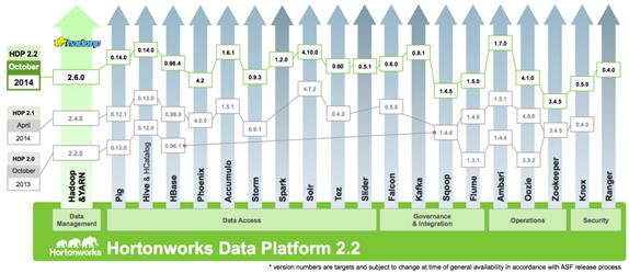
Pre-Requisites for HDP Installation
This section details the pre-requisites for HDP Installation such as setting up of HDP Repositories.
HortonWorks Repo
From a host connected to the Internet, download the Hortonworks repositories as shown below and transfer it to the admin node.
mkdir -p /tmp/Hortonworks
cd /tmp/Hortonworks/
1. Download Hortonworks HDP Repo
wget http://public-repo-1.hortonworks.com/HDP/centos6/HDP-2.2.0.0-centos6-rpm.tar.gz
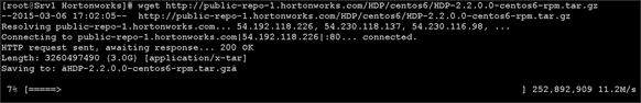
2. Download Hortonworks HDP-Utils Repo
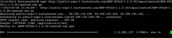
3. Download Ambari Repo
wget http://public-repo-1.hortonworks.com/ambari/centos6/ambari-1.7.0-centos6.tar.gz
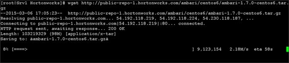
4. Copy the repository directory to the admin node
scp -r /tmp/Hortonworks/ rhel1:/var/www/html
5. Extract the contents of the archives
cd /var/www/html/Hortonworks
tar -zxvf HDP-2.2.0.0-centos6-rpm.tar.gz
tar -zxvf HDP-UTILS-1.1.0.20-centos6.tar.gz
tar -zxvf ambari-1.7.0-centos6.tar.gz
6. Create the hdp.repo file with following contents
vi /etc/yum.repos.d/hdp.repo
[HDP-2.2.0.0]
name=Hortonworks Data Platform Version - HDP-2.2.0.0
baseurl=http://rhel1/Hortonworks/HDP/centos6/2.x/GA/2.2.0.0
gpgcheck=0
enabled=1
priority=1
[HDP-UTILS-1.1.0.20]
name=Hortonworks Data Platform Utils Version - HDP-UTILS-1.1.0.20
baseurl= http://rhel1/Hortonworks/HDP-UTILS-1.1.0.20/repos/centos6
gpgcheck=0
enabled=1
priority=1
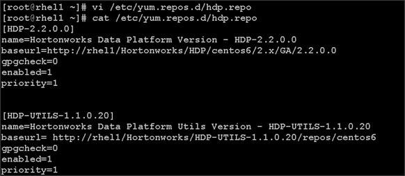
7. Create the Ambari repo file with following contents
vi /etc/yum.repos.d/ambari.repo
[Updates-ambari-1.7.0]
name=ambari-1.7.0 - Updates
baseurl=http://rhel1/Hortonworks/ambari/centos6/1.x/updates/1.7.0
gpgcheck=0
enabled=1
priority=1
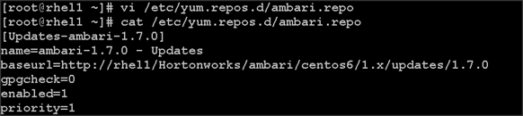
8. From the admin node copy the repo files to /etc/yum.repos.d/ of all the nodes of the cluster.
clush -a -b -c /etc/yum.repos.d/hdp.repo --dest=/etc/yum.repos.d/
clush -a -b -c /etc/yum.repos.d/ambari.repo --dest=/etc/yum.repos.d/
Installing Ambari Server
Follow the steps below to install HDP.
9. Install and Setup Ambari Server on rhel1
yum -y install ambari-server
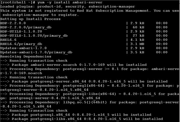
ambari-server setup –j $JAVA_HOME -s
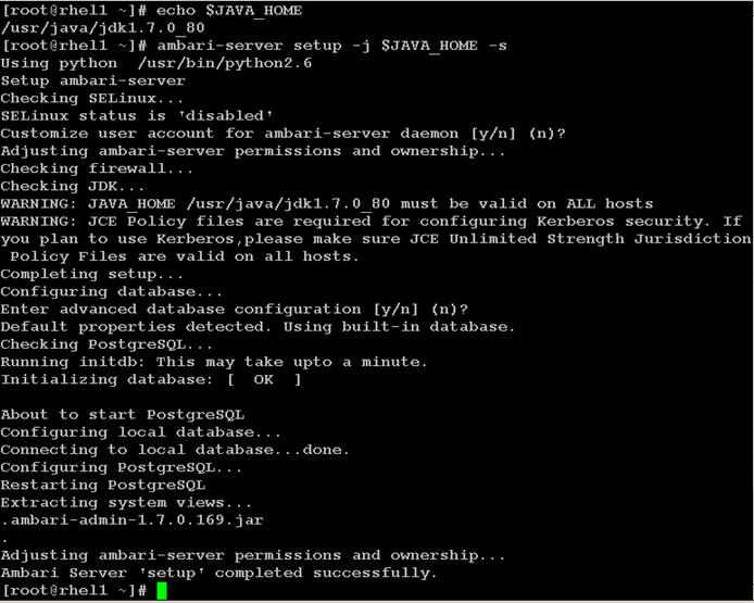
ambari-server start
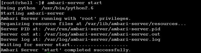
12. Confirm Ambari Server Startup
ps -ef | grep ambari-server
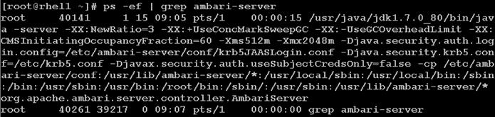
Log into Ambari Server
Once the Ambari service has been started, access the Ambari Install Wizard through the browser.
1. Point the browser to http://<ip address for rhel1>:8080
2. Log in to the Ambari Server using the default username/password: admin/admin. This can be changed at a later period of time.
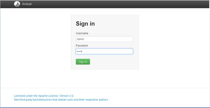
Once logged in the “Welcome to Apache Ambari” window appears.
Creating a Hadoop Cluster
Use the following steps to create a Hadoop cluster using Ambari.
1. Click Launch install wizard button.
2. At the Get started page type “VoraOnUCS” as name for the cluster in the text box.
3. Click the Next button.
Select Stack
In the following screen
1. Select HDP 2.2 stack
2. Expand “Advanced Repository Options”. Under the advanced repository option:
a. Select RedHat 6 checkbox
b. Uncheck rest of the checkbox
c. Update the Redhat 6 HDP-2.2 URL to http://rhel1/Hortonworks/HDP/centos6/2.x/GA/2.2.0.0
d. Update the Redhat 6 HDP-UTILS-1.1.0.20 URL to
e. http://rhel1/Hortonworks/HDP-UTILS-1.1.0.20/repos/centos6
3. Click Next to continue the installation.
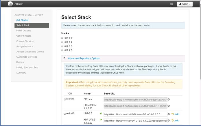
HDP Installation
In order to build up the cluster, the install wizard needs to know general information about how the cluster has to be set up. This requires providing the Fully Qualified Domain Name (FQDN) of each of the host. The wizard also needs to access the private key file that was created in Set Up Password-less SSH. It uses these to locate all the hosts in the system and to access and interact with them securely.
1. Use the Target Hosts text box to enter the list of host names, one per line. One can also use ranges inside brackets to indicate larger sets of hosts.
2. Select the option Provide your SSH Private Key in the Ambari cluster install wizard
a. Copy the contents of the file /root/.ssh/id_rsa on rhel1 and paste it in the text area provided by the Ambari cluster install wizard.
![]() Note
Note ![]() Make sure there is no extra white space after the text-----END RSA PRIVATE KEY-----
Make sure there is no extra white space after the text-----END RSA PRIVATE KEY-----
3. Click the Register and Confirm button to continue.
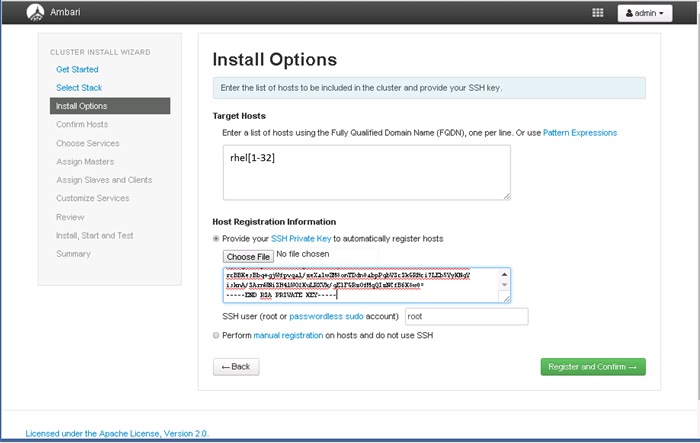
Hostname Pattern Expressions
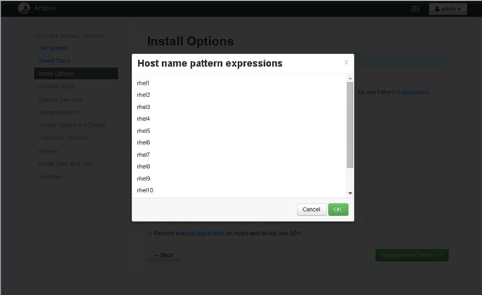
Confirm Hosts
This screen allows you to ensure that Ambari has located the correct hosts for the cluster and to check those hosts to make sure they have the correct directories, packages, and processes to continue the install.
If any hosts were selected in error, it can be removed by selecting the appropriate checkboxes and clicking the grey Remove Selected button. To remove a single host, click the small white Remove button in the Action column.
When the lists of hosts are confirmed, click Next.
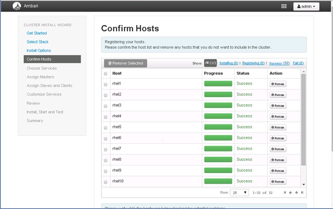
Choose Services
HDP is made up of a number of components. See Understand the Basics for more information.
1. Select none, to unselect all items
2. Select, HDFS, YARN+MapReduce2, Nagios, Ganglia and Zookeeper services
3. When you have made your selections, click Next.
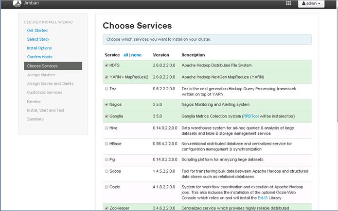
![]() Hive will be installed at a later stage.
Hive will be installed at a later stage.
Assign Masters
The Ambari install wizard attempts to assign the master nodes for various services that have been selected to appropriate hosts in the cluster. The right column shows the current service assignments by host, with the hostname and its number of CPU cores and amount of RAM indicated.
1. Reconfigure the service assignment to match the table shown below
| Service Name |
Host |
| NameNode |
rhel1 |
| SNameNode |
rhel2 |
| DataNodes / NodeManager |
rhel3 – rhel32 |
| HistoryServer |
rhel2 |
| ResouceManager |
rhel2 |
| Nagios Server |
rhel1 |
| Ganglia Collector |
rhel1 |
| Zookeeper |
rhel1, rhel2, rhel3 |
| Clients (HDFS, YARN, MapReduce2, ZooKeeper) |
rhel1 – rhel32 |

![]() Note: On a small cluster (<16 nodes), consolidate all master services to run on one or two nodes. For large clusters (>= 32 nodes), deploy master services across 3 nodes, and consider adding two additional zookeeper nodes.
Note: On a small cluster (<16 nodes), consolidate all master services to run on one or two nodes. For large clusters (>= 32 nodes), deploy master services across 3 nodes, and consider adding two additional zookeeper nodes.
2. Click the Next button.
Assign Slaves and Clients
The Ambari install wizard attempts to assign the slave components (DataNodes, NodeManagers, RegionServers, Supervisor and Flume) to appropriate hosts in the cluster. Reconfigure the service assignment to match below:
1. Assign DataNode, NodeManager, RegionServer ,Supervisor and Flume on nodes rhel3- rhel32
2. Assign Client to all nodes
3. Click the Next button.
| Client Service Name |
Host |
| DataNode |
rhel3 to rhel32 |
| NodeManager |
rhel3 to rhel32 |
| Client |
All nodes, rhel3 - rhel32 |
| Vora Extension |
rhel1 |
| Vora |
rhel1 – rhel32 |
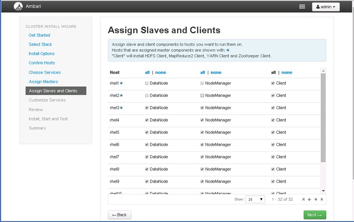
Customize Services
This section presents with a set of tabs that manage configuration settings for Hadoop components. The wizard attempts to set reasonable defaults for each of the options here, but this can be modified to meet specific requirements. Following sections provide configuration guidance that should be refined to meet specific use case requirements.
Following are the changes made:
· Memory and service level setting for each component and service level tuning
· Customize the log locations of all the components to ensure growing logs do not cause the SSDs to run out of space
HDFS
In Ambari, choose HDFS Service from the left tab and go to “Configs” tab.
Use the “Search” box on top to filter for the properties mentioned in the tab to update the values
HDFS JVM Settings
Update the following HDFS configurations in Ambari
| Property Name |
Value |
| NameNode Directory |
/data/disk1/hadoop/hdfs/namenode |
| NameNode Java Heap Size |
4096 |
| SNameNode Directory |
/data/disk1/hadoop/hdfs/namesecondary |
| Hadoop maximum Java heap size |
4096 |
| DataNode maximum Java heap size |
4096 |
| Datanode Volumes Failure Toleration |
3 |
Manage Config Groups for Archival Nodes
Ambari initially assigns all hosts in your cluster to one default configuration group for each service installed.

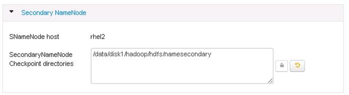
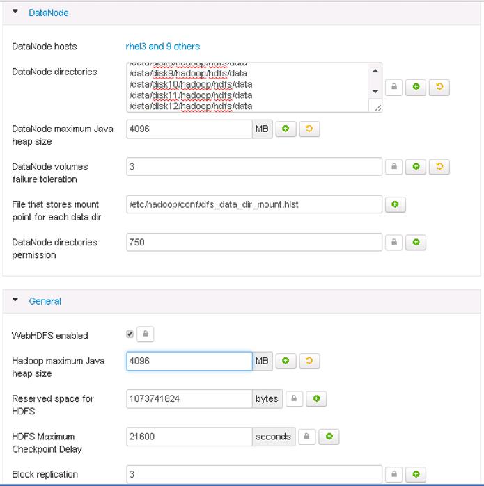
4. Scroll down to the “Data Node directories” property and enter the following directory paths in that text box.
/data/disk1/hadoop/hdfs/data
/data/disk2/hadoop/hdfs/data
/data/disk3/hadoop/hdfs/data
/data/disk4/hadoop/hdfs/data
/data/disk5/hadoop/hdfs/data
/data/disk6/hadoop/hdfs/data
/data/disk7/hadoop/hdfs/data
/data/disk8/hadoop/hdfs/data
/data/disk24/hadoop/hdfs/data
Update Log Directory
Change the default log location by finding the Log Dir property and modifying the /var prefix to /data/disk1

MapReduce2
In Ambari, choose MapReduce Service from the left tab and go to “Configs” tab.
Use the “Search” box on top to filter for the properties mentioned in the tab to update the values.
Update the following MapReduce configurations:
| Property Name |
Value |
| Default virtual memory for a job's map-task |
4096 |
| Default virtual memory for a job's reduce-task |
8192 |
| Map-side sort buffer memory |
1638 |
| yarn.app.mapreduce.am.resource.mb |
4096 |
| mapreduce.map.java.opts |
-Xmx3276m |
| mapreduce.reduce.java.opts |
-Xmx6552m |
| yarn.app.mapreduce.am.command-opts |
-Xmx6552m |
Similarly under MapReduce2 tab, change the default log location by finding the Log Dir property and modifying the /var prefix to /data/disk1.
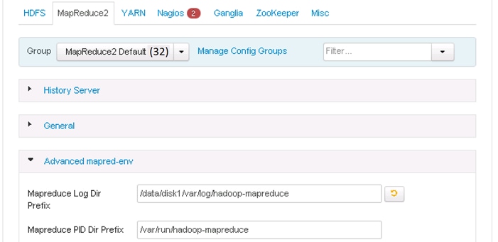
YARN
In Ambari, choose YARN Service from the left tab and go to “Configs” tab.
Use the “Search” box on top to filter for the properties mentioned in the tab to update the values
Update the following YARN configurations
| Property Name |
Value |
| ResourceManager Java heap size |
4096 |
| NodeManager Java heap size |
2048 |
| yarn.nodemanager.resource.memory-mb |
184320 |
| YARN Java heap size |
4096 |
| yarn.scheduler.minimum-allocation-mb |
4096 |
| yarn.scheduler.maximum-allocation-mb |
184320 |
Similarly under YARN tab, change the default log location by finding the Log Dir property and modifying the /var prefix to /data/disk1.
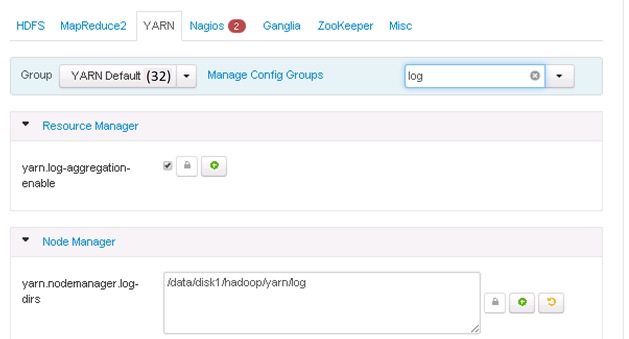
Nagios
On the Nagios tab, it is required to provide:
Nagios admin password (as per organizational policy standards)
Hadoop Admin Email
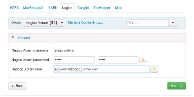
Ganglia
No changes are required.
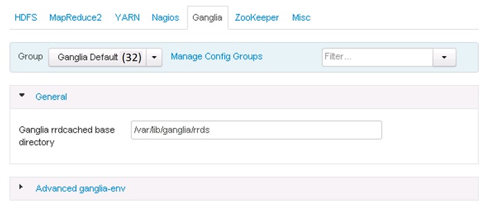
Zookeeper
Similarly under Zookeeper tab, change the default log location by finding the Log Dir property and modifying the /var prefix to /data/disk1
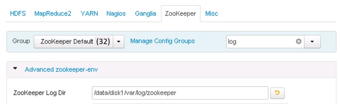
Misc
No changes are required.
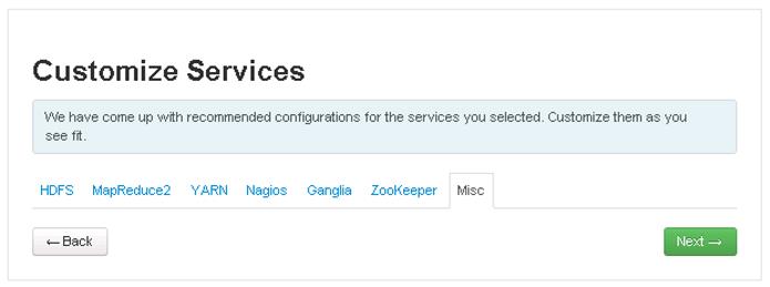
Review
The assignments that have been made are displayed. Check to ensure everything is correct before clicking on Deploy button. If any changes are to be made, use the left navigation bar to return to the appropriate screen.
Once review is complete, click the Deploy button.
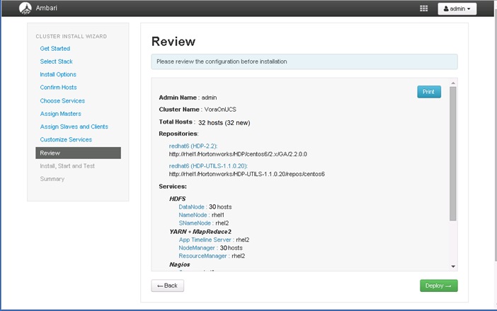
The progress of the install is shown on the screen. Each component is installed and started and a simple test is run on the component. The next screen displays the overall status of the install in the progress bar at the top of the screen and a host-by-host status in the main section.
To see specific information on what tasks have been completed per host, click the link in the Message column for the appropriate host. In the Tasks pop-up, click the individual task to see the related log files. Select filter conditions by using the Show dropdown list. To see a larger version of the log contents, click the Open icon or to copy the contents to the clipboard, use the Copy icon.
Depending on which components are installing, the entire process may take 10 or more minutes.
When successfully installed and started the services appears, click Next.

Summary of Install Process
The Summary page gives a summary of the accomplished tasks. Click Complete.
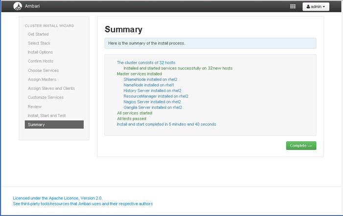
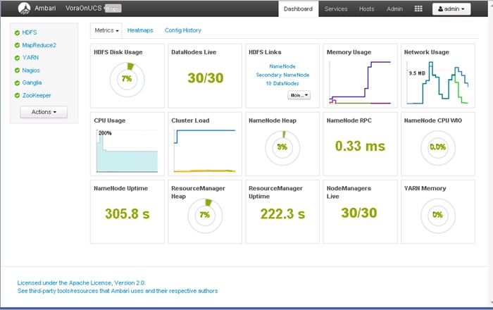
Installing Apache Spark on admin node
SAP HANA Vora™ is an in-memory query engine that plugs into the Apache Spark execution framework to provide enriched interactive analytics on Hadoop. The admin node (rhel1) will be configured to serve as the Vora client node as well. Thus the following packages are necessary.
· Scala programming language platform
· Apache Spark 1.4.1
· SAP HANA Vora Extension packages.
This section provides the steps necessary to perform the first two parts. The Vora Extension packages shall be installed at a later stage.
Prepare HDFS for Spark and Vora access
Create a dedicated Vora user
1. Create a new user by name “vora” of group “users”
2. Login as HDFS user
3. Create a directory /user/vora on HDFS
4. Change owner of the directory /user/vora to user “vora”.
useradd -m vora -g users
su - hdfs
hadoop fs -mkdir /user/vora
hadoop fs -chown vora /user/vora
hadoop fs -ls /user
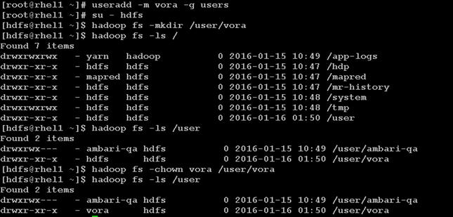
Create a Test file – test.csv with some data
1. Login as vora user
2. Create a temporary file test.csv
3. Run the following commands to create a temporary data file called test.csv
vi ./test.csv
![]() Add the following contents into the test.csv file.
Add the following contents into the test.csv file.
1,Rack,C240M4
2,Rack,C220M4
3,Rack,C3260
4,Blade,B200M4
5,FI,6296

cat ./test.csv

Perform a simple HDFS Read/write test
1. Copy that file – test.csv onto HDFS
2. Read from HDFS
hadoop fs -put test.csv
hadoop fs -cat /user/vora/test.csv

Install Scala
1. Download the latest release of Scala RPM from the scala-lang.org website (http://www.scala-lang.org/download/all.html)
2. Copy the rpm file over to the /tmp directory of the admin node(rhel1).
Install the Scala language platform using the following command.
rpm -ivh /tmp/scala-2.11.7.rpm
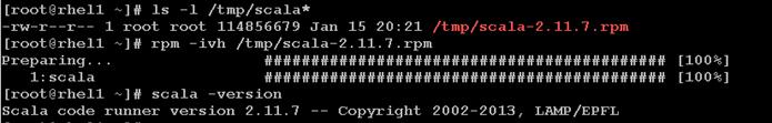
Install Apache Spark
Spark is a fast and general processing engine compatible with Hadoop data. It can run in Hadoop clusters through YARN or Spark's standalone mode, and it can process data in HDFS, HBase, Cassandra, Hive, and any Hadoop InputFormat. It is designed to perform both batch processing (similar to MapReduce) and new workloads like streaming, interactive queries, and machine learning.
1. Go to the download page @ apache.spark.org (http://spark.apache.org/downloads.html)
2. Select Spark release as 1.4.1
3. Choose the Package type as “Pre-built for Hadoop 2.6 and later”
4. Click on Download Spark URL to download the spark-1.4.1-bin-hadoop2.6.tgz
5. Copy the binary over to the /tmp directory of the admin node (rhel1).
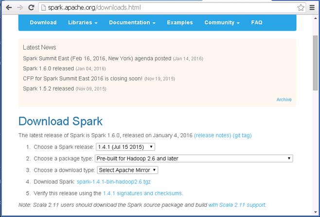
6. Create a directory “/opt/spark” in the admin node.
7. Un-tar the Spark archive onto the newly created directory.
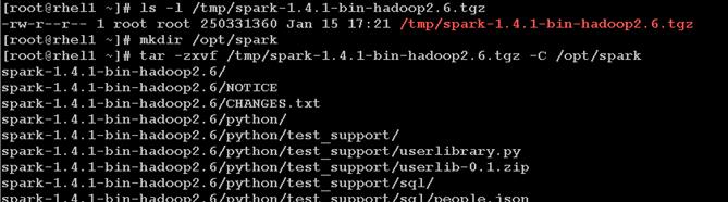
8. Create a file called spark-home.sh and copy it over to /etc/profile.d with the following contents.
vi /tmp/spark-home.sh
export HADOOP_CONF_DIR=/etc/hadoop/conf
export SPARK_HOME=/opt/spark/spark-1.4.1-bin-hadoop2.6
export SPARK_CONF_DIR=$SPARK_HOME/conf
export PATH=$PATH:$SPARK_HOME/bin

9. Copy over the newly created script spark-home.sh to /etc/profile.d to setup these environment variables.
cp /tmp/spark-home.sh /etc/profile.d
10. Logoff and log back in onto the admin node (rhel1) as user root and verify if the new Spark environment variables are set up correctly.
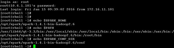
11. Create a new set of Spark Default configurations at

12. In this $SPARK_HOME/conf/spark-defaults.conf file, update the following parameters to match your configurations.
spark.driver.memory 512m
spark.driver.extraJavaOptions -Dhdp.version=2.2.0.0-2041
spark.executor.memory 512m
spark.executor.cores 20
spark.master yarn-client
spark.vora.hosts rhel3,rhel4,rhel5,rhel6,rhel7,rhel8,rhel9,rhel10,rhel11,rhel12, ,rhel13,rhel14,rhel15,rhel16,rhel17,rhel18,rhel19,rhel20,rhel21,rhel22,rhel23,rhel24,rhel25,rhel26,rhel27,rhel28,rhel29,rhel30,rhel31,rhel32
spark.vora.namenodeurl rhel1:8020
spark.vora.zkurls rhel1:2181,rhel2:2181,rhel3:2181
spark.yarn.am.extraJavaOptions -Dhdp.version=2.2.0.0-2041
spark.yarn.queue default
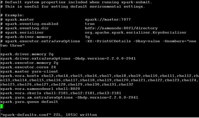
Testing Apache Spark
1. Login as user vora in the admin node (rhel1)
2. Execute spark-shell
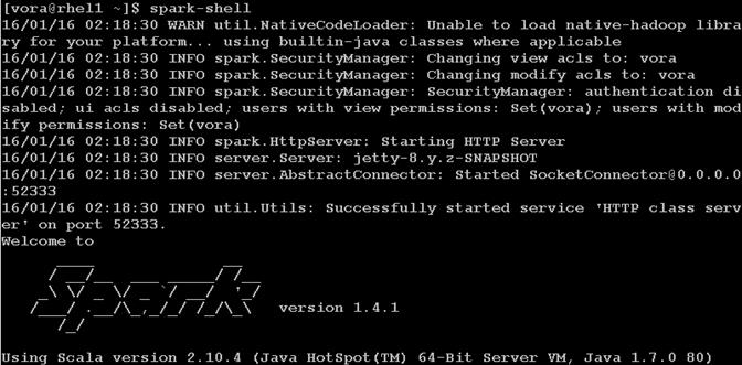
This should end in a successful “scala” REPL prompt.
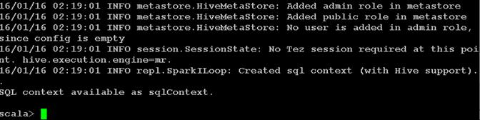
3. Submit a Spark job get PI value
spark-submit --class org.apache.spark.examples.SparkPi --num-executors 12 $SPARK_HOME/lib/spark-examples*.jar 10 2>/dev/null

4. Verify the job in the Resource manager
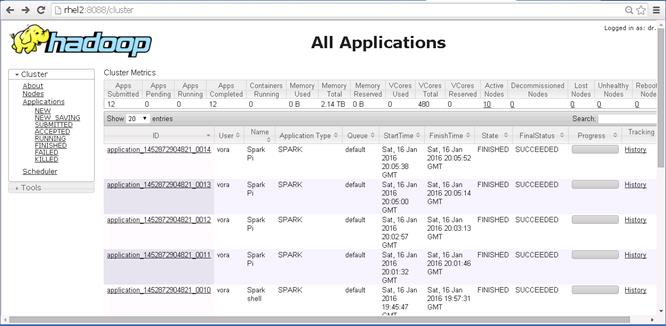
5. Take a closer look at the Spark Pi job.
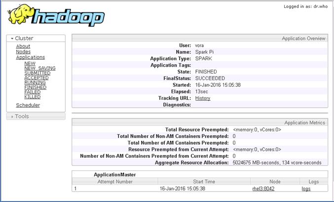
Preparing to Install SAP HANA Vora
The SAP HANA Vora SQL engine is a service that you add to your existing Hadoop installation. SAP HANA Vora instances hold data in memory and boost the performance of out-of-the box Spark. To increase execution performance on the node level, you add an SAP HANA Vora instance to each compute node so that it contains the following:
· A Spark Worker
· An SAP HANA Vora engine
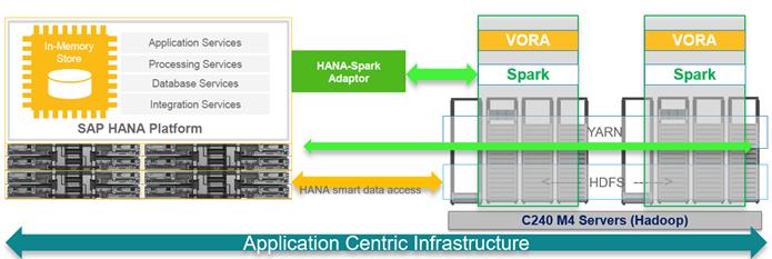
The SAP HANA Vora extension library allows SAP HANA Vora to be accessed through Spark. It also provides additional functionality, such as a hierarchy implementation, which allows you to build hierarchies and run hierarchical queries.
This Vora extension package must be installed on the same node on which Spark is installed.
To run SAP HANA Vora on RHEL 6.6, an additional runtime environment for GCC 4.7 is required, which you can add by installing the RPM package compat-sap-c++ (see also SAP Note 2001528 ).
Install the C++ compatibility package
To be able to access the library, subscription for "Red Hat Enterprise Linux Server for SAP HANA" is required. This allows the Hadoop servers to the "RHEL Server SAP HANA" channel on the Red Hat Customer Portal or your local Satellite server. After appropriately subscribing the servers to the channel, the output of yum repolist should contain the following:
rhel-x86_64-server-sap-hana-6 RHEL Server SAP HANA (v. 6 for 64-bit x86_64)
GCC 4.7 libstdc++ library can then be installed using the following command:
yum install compat-sap-c++
clush –a yum install compat-sap-c++
The bBelow method shows how to manually install C++ compatibility package across all the nodes of the Vora cluster.
1. Copy over the C++ SAP compatibility package to the /tmp directory of the admin node (rhel1).
2. Copy the file over to all the nodes of the cluster using the below command.
clush -a -c /tmp/compat-sap-c++-4.7.2-10.el6_5.x86_64.rpm

3. Install the C++ SAP compatibility package to all the nodes of the cluster.
clush -a "rpm -ivh /tmp/compat-sap-c++-4.7.2-10.el6_5.x86_64.rpm"
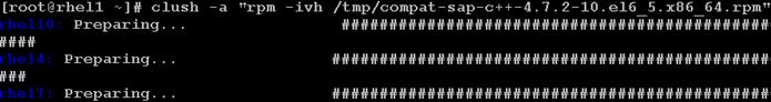
SAP HANA
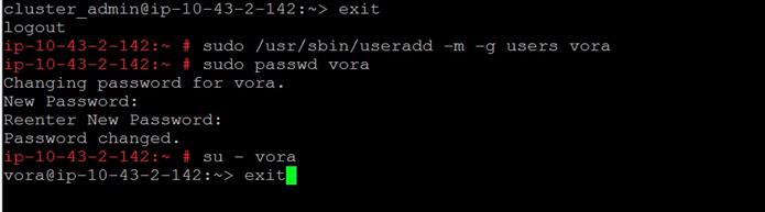
rhel1 (/tmp/ compat-sap-c++-4.7.2-10.el6_5.x86_64.rpm)
Installing SAP HANA Vora Engine
Download and distribute Vora Ambari package
1. Download ambaripkg-1.1.<version>.tar.gz OR VORA_AM_<version>.tgz (from the SAP Software Download Center at https://support.sap.com/swdc to the admin node (rhel1).
![]()
![]() The actual filename downloaded from the SAP Software Download Center would be VORA_AM_<version>.tgz.
The actual filename downloaded from the SAP Software Download Center would be VORA_AM_<version>.tgz.
2. Copy this file over to the /tmp directory of all the servers of the Vora cluster.
clush -a -c /tmp/ambaripkg-1.1-ms-19.tar.gz

Install Vora Engine on the Ambari Server
3. Go to directory /var/lib/ambari-server/resources/stacks/HDP/2.2/services on the admin node where the Ambari server is installed. Ie. The admin node (rhel1).
4. Extract the contents of the Vora-Ambari package present in the /tmp directory.
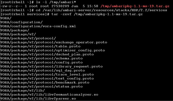
5. Restart the Ambari server with the following command
ambari-server restart
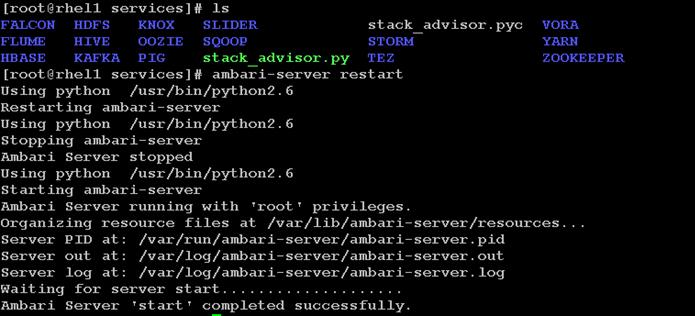
Install Vora Engine on all Vora client nodes.
1. Install the Vora Ambari package on all the data nodes using clush commands
clush -a -x rhel1 "tar -zxf /tmp/ambaripkg-1.1-ms-19.tar.gz -C /var/lib/ambari-agent/cache/stacks/HDP/2.2/services/"
clush –B -a -x rhel1 "ls -l /var/lib/ambari-agent/cache/stacks/HDP/2.2/services/"
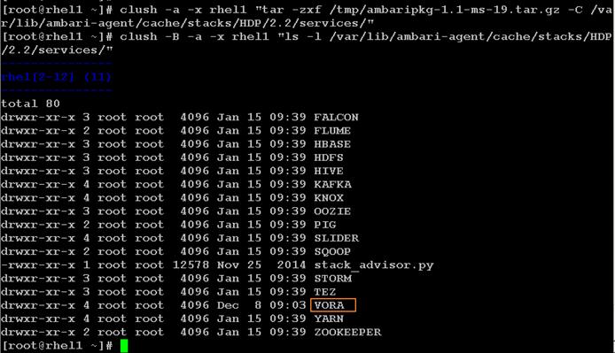
Install SAP HANA Vora on the client nodes (all the data nodes)
1. Log onto Ambari console.
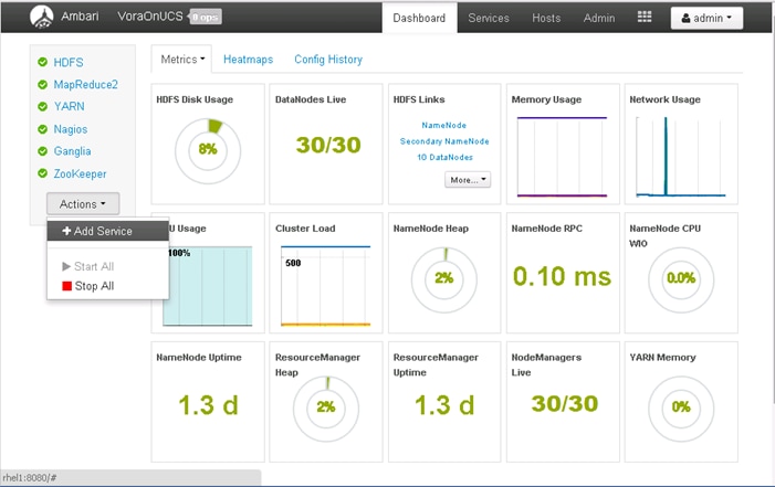
2. In the Add Service Wizard, scroll down and click on the check box next to SAP HANA Vora to choose the VORA service and Click Next.
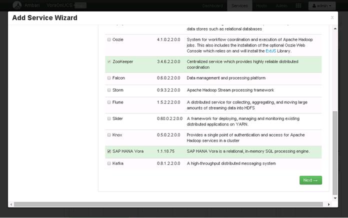
3. Click “all” hyperlink, followed by clicking on the check box against hosts “rhel1” and “rhel2”, so that all the nodes where Node Manager and Data Node services are running will also run the SAP HANA Vora service. Click Next to continue.
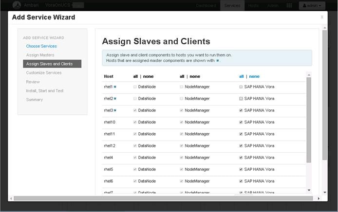
4. Customize the SAP HANA Vora log directory in the “Advanced vora-config” section, to change the location to “/data/disk1/var/log/vora”. Click Next to continue.
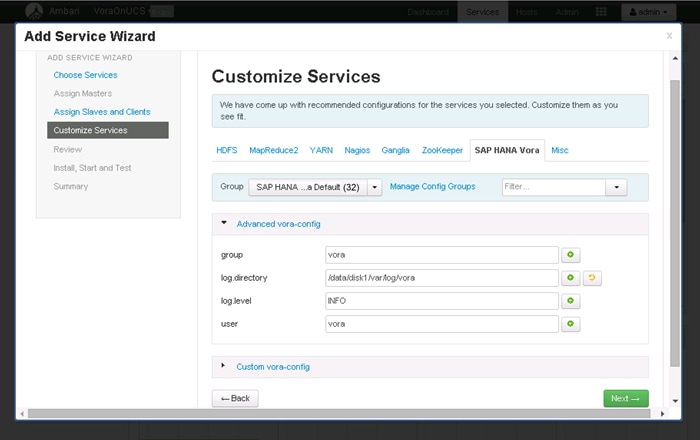
5. Check service installation checkpoint before the actual VORA deployment. Click Deploy to continue.

6. Observe the SAP HANA Vora installation in progress.
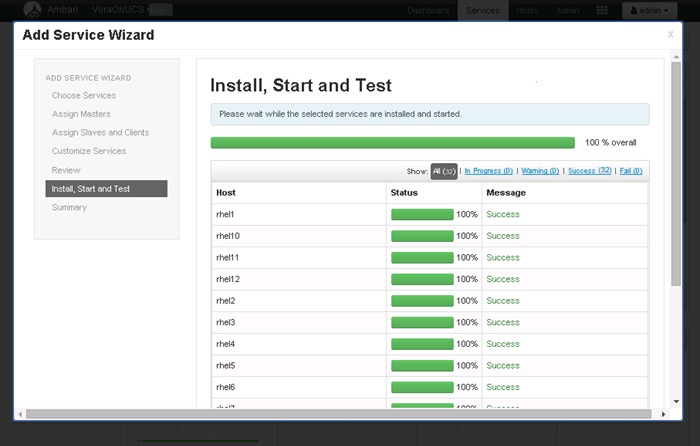
7. Once the SAP HANA Vora service is installed and started as indicated by the progress 100%, click Next to continue.
![]() Once this process is complete, the core services like HDFS, YARN, MapReduce2, Nagios and Ganglia monitoring services will need to be restarted.
Once this process is complete, the core services like HDFS, YARN, MapReduce2, Nagios and Ganglia monitoring services will need to be restarted.
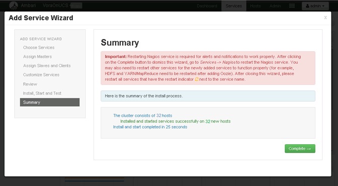
8. Click Complete to finish the installation process.
![]() At this point a number of services will need to be restarted will be displayed.
At this point a number of services will need to be restarted will be displayed.
9. Click on the <Restart> button to choose “Restart All” to restart all the HDFS services.
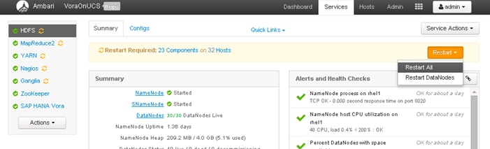
10. Click on <Confirm Restart All> to confirm.
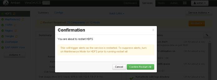
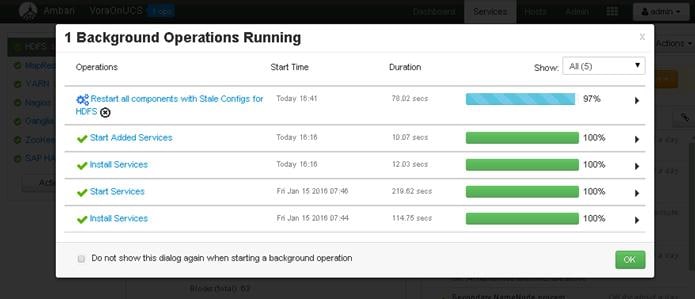
![]() Likewise, all the other services that require a restart will need to be restarted.
Likewise, all the other services that require a restart will need to be restarted.
![]() No need to wait for the completion of the restart operations to complete, Ambari would perform the restart one after another.
No need to wait for the completion of the restart operations to complete, Ambari would perform the restart one after another.
11. Now select the MapReduce2 service in the navigation pane, and Click on the <Restart> button to MapReduce2 service on all nodes.
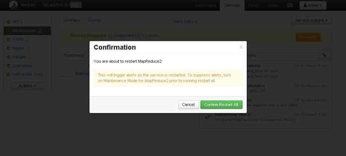
12. Now select the YARN service in the navigation pane, and Click on the <Restart> button to YARN service on all nodes.
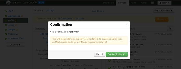
13. Restart Nagios, Ganglia services by following the same process.
14. Installing Spark Controller for accessing SAP HANA Vora Data sources from SAP HANA
15. SAP HANA Spark Controller and Hive meta store on Hadoop cluster are required for enabling SAP HANA to access the data presentin SAP HANA Vora cluster.
16. Ambari does not allow the installation of just the Hive meta store, so this section shows the steps required to install the Hive service on the admin node. Since, Pig and Tez are dependent services, they would also get installed as a part of the Hive installation.
Installing the SAP HANA Vora Extension
In order to make use of the SAP HANA Vora engine in Spark, the SAP HANA Vora Spark extension library must be installed on the same node where Apache Spark is installed (i.e. the admin node rhel1).
1. Download the library package VORA_SE<version>.TGZ from the SAP Software Download Center at https://support.sap.com/swdc, and copy this file over to the /tmp directory of the admin node (rhel1)
2. Log onto the admin node (rhel1) as the root user.
3. Switch the user to the standard vora user i.e. vora.
sudo -iu vora
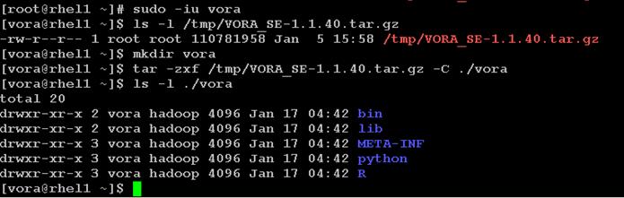
Creating a Table from SAP HANA Vora Shell
In this section, we will make access the SAP HANA Vora shell as the “vora” user and verify the installation by creating a table and loading data into it from a file stored in HDFS.
For this verification, the test.csv that was used to verify the vora user’s access to HDFS in the earlier section.
1. Create a test.csv file at folder /user/vora/ on the HDFS.
2. Verfiy the contents using the hdfs command.
hdfs fs -cat /usr/vora/test.csv

3. As the vora user, change the directory into the Vora Extension package’s bin directory.
cd/home/vora/vora/bin
4. Open a Spark shell by using the start-spark-shell.sh shell script.
/start-spark-shell.sh --master yarn-client

![]() Once the Spark(Vora) shell has been started, the “scala” prompt appears as shown below.
Once the Spark(Vora) shell has been started, the “scala” prompt appears as shown below.

5. Create table using the Vora SQL engine context, which can be used to load the contents of the file test.csv on HDFS.
import org.apache.spark.sql.SapSQLContext
import org.apache.spark.sql.SapSQLContext
val vc = new SapSQLContext(sc)
val testsql = """
CREATE TABLE ucs_table001 (rNum int, sType string, sModel string)
USING com.sap.spark.vora
OPTIONS (
tablename "ucs_table001",
paths "/user/vora/test.csv"
)"""
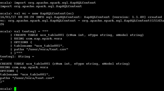
6. Use the vc SQL context to create the table.
vc.sql(testsql)
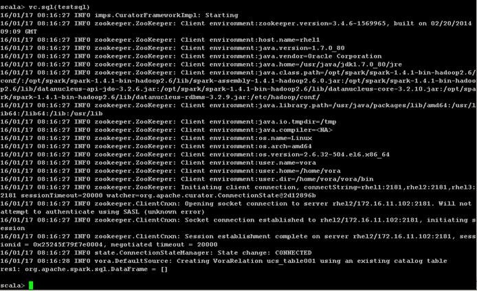
7. Display the tables uing the SQL context
vc.sql(“show tables”).show()
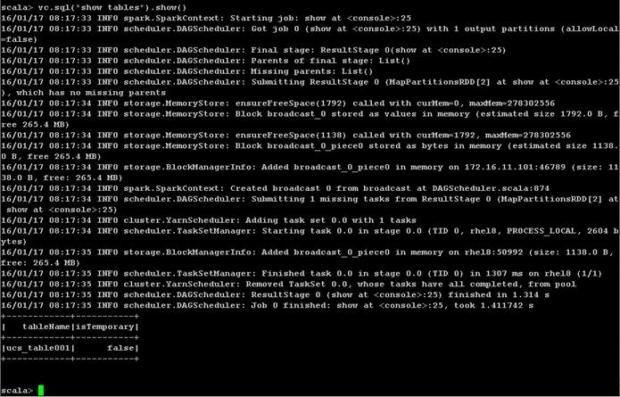
8. Display the contents of the table “ucs_table001” by using the SQL “SELECT” statement as follows:
vc.sql(“SELECT * FROM ucs_table001”).show()
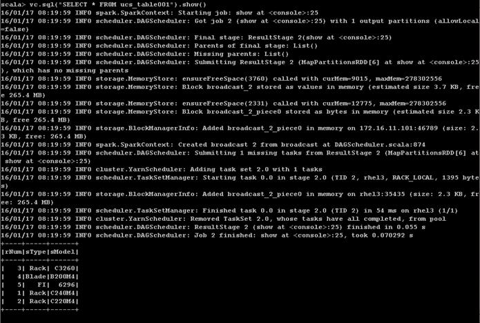
The contents of the entire table are displayed. This verifies the Vora engine working properly.
![]() At this point, the SAP HANA Vora cluster is fully configured and ready for use.
At this point, the SAP HANA Vora cluster is fully configured and ready for use.
![]() Follow the appropriate documentation found at https://help.sap.com/hana_vora_re for making use of this SAP HANA Vora cluster along with SAP HANA as necessary.
Follow the appropriate documentation found at https://help.sap.com/hana_vora_re for making use of this SAP HANA Vora cluster along with SAP HANA as necessary.
SAP HANA Spark Controller and Hive meta store on Hadoop cluster are required for making the data available in SAP HANA Vora cluster to the SAP HANA database system and the SAP HANA Vora cluster running on Cisco UCS.
Ambari does not allow the installation of just the Hive meta store, so this section shows the steps required to install the Hive service on the admin node. Since, Pig and Tez are dependent services, they would also get installed as a part of the Hive installation.
Install Hive
1. Log onto the Ambari web UI.
2. From the Home screen, click on the button <Actions> button and choose <Add Service>.
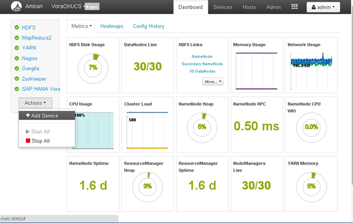
3. Select Hive service. Click Next to continue
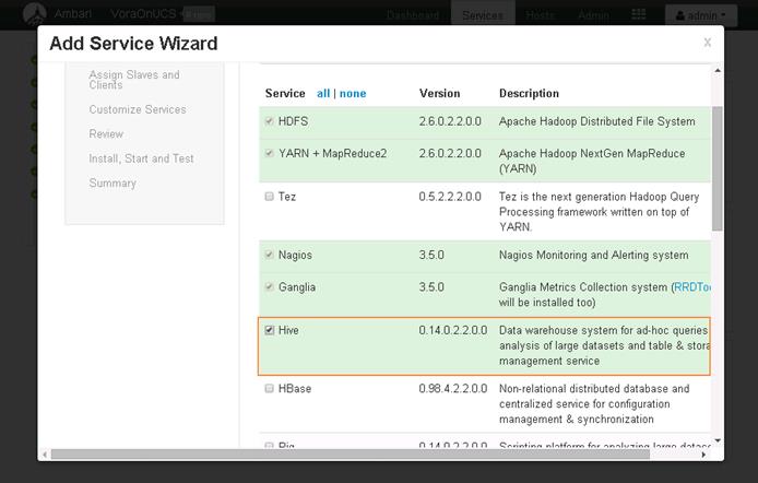
4. Click OK to accept the services Tez and Pig as well.
![]() Ambari will not install Hive without Pig and Tez.
Ambari will not install Hive without Pig and Tez.
5. Choose admin node (rhel1) as the target server to install the Hive services.
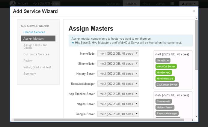
6. Click on hyperlink “all” to enable Hive Client installation on all the servers. Click Next.
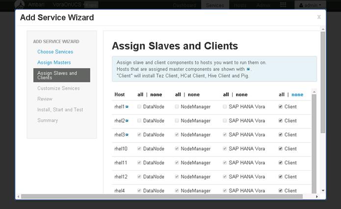
7. Click on the Hive tab; In the Hive meta store section, choose New MySQL database, and enter the Hive database passwords.
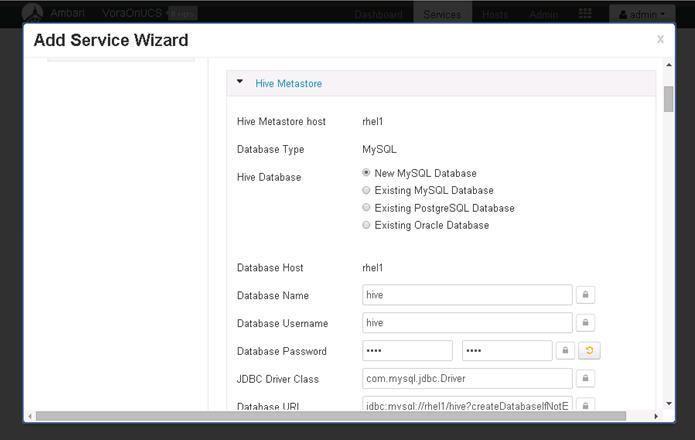
![]() Alternatively, an existing database could be chosen as the meta data store.
Alternatively, an existing database could be chosen as the meta data store.
8. In Advanced hive-config section, modify the log URL to make use of the /data/disk1/var/log/hive as the “Hive Log Dir” instead of the default.
9. In the Advanced webhcat-env section, update the WebHCat Log Dir to /data/disk1/var/log/webhcat. Click Next to continue.
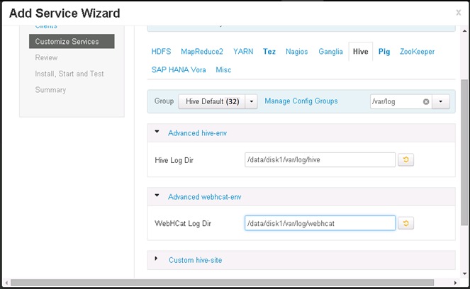
10. Review the configuration in the next screen, and Click <Deploy> to deploy the Hive services.
11. Once the installation is complete, Click on Complete to finish the installation.

![]() Hive installation is now complete. The services will need to be restarted. It is best to stop all services, and restart all of them at once.
Hive installation is now complete. The services will need to be restarted. It is best to stop all services, and restart all of them at once.
12. Click on <Actions> and choose Stop all to stop all the services.
13. Once all the services are completely stopped, Click <Actions> and Choose “Start All” services.
![]() The operations “Stop All” and “Start All” services would take about 5 to 10 minutes to complete.
The operations “Stop All” and “Start All” services would take about 5 to 10 minutes to complete.
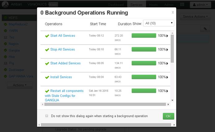
14. Hive installation is now complete.
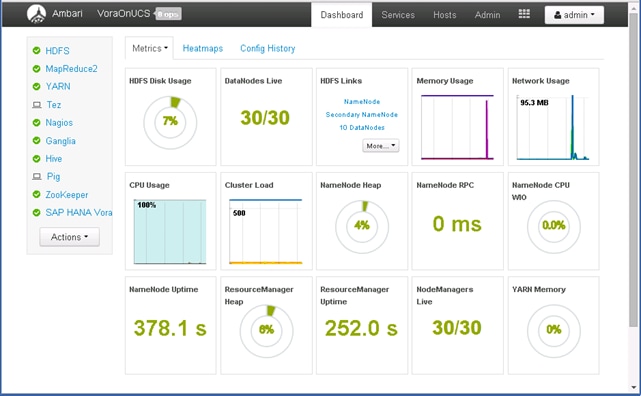
Test the Hive Installation
1. Log onto the admin node (rhel1) using SSH.
2. Switch the user to “hive”
sudo -iu hive
3. Create a file called “hive_test.sql” and add the following contents to it.
vi hive_test.sql
CREATE SCHEMA IF NOT EXISTS ucs;
DROP TABLE IF EXISTS ucs.infra;
CREATE TABLE IF NOT EXISTS ucs.infra (
id int,
type string,
gen string,
name string,
spec double,
features string
) ROW FORMAT DELIMITED FIELDS TERMINATED BY ',' ;
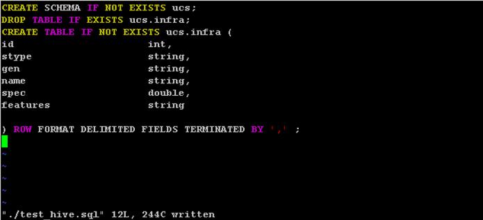
4. Create a data file called ucs_servers.dat and add the following content.
vi ucs_infra.dat
1,UCS FI,2nd-Gen,FI 6296,2,96 Unified Ports
2,UCS FI,2nd-Gen,FI 6248,1,48 Unified Ports
3,Rack Server,4th-Gen,C240 M4,2,Dual-10GigE-VIC:SFF:
4,Rack Server,4th-Gen,C220 M4,1,Dual-10GigE-VIC:SFF:
5,Rack Server,4th-Gen,C460 M4,4,Dual-10GigE-VIC:SFF:SAP HANA Appliance
6,Rack Server,2nd-Gen,C3260,4,2 x Dual-10GigE-VIC:2 X Servers:56 LFF 7.2K SAS
7,Blade Server,4th-Gen,B200 M4,.5,Dual-10GigE-VIC:SFF
8,Blade Server,4th-Gen,B460 M4,2Dual-10GigE-VIC:SFF:SAP HANA Appliance
9,UCS FI,3rd-Gen,FI 6332-16UP,1,24 40GigE Ports:16 Unified Ports
10,UCS FI,3rd-Gen,FI 6332,1,32 40GigE Ports
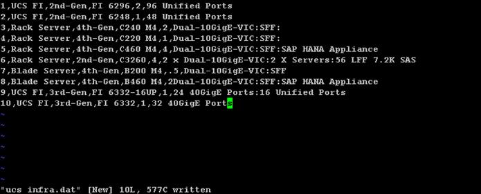
5. Execute hive to create the schema.
hive -f ./test_hive.sql
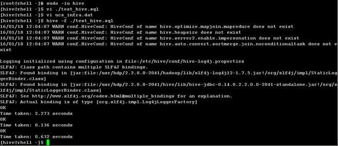
6. Type “hive” to get the Hive prompt and display the databases using the command:
SHOW DATABASES;
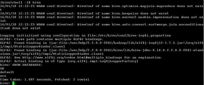
7. Load the ucs_infra.dat data file onto HDFS inside the ucs.db directory managed by Hive.
8. Adjust the privileges.
hdfs dfs -put ./ucs_infra.dat /apps/hive/warehouse/ucs.db/infra
hdfs dfs -ls /apps/hive/warehouse/ucs.db/infra
hdfs dfs -chown -R hive:hdfs /apps/hive/warehouse/ucs.db
9. Load the table, and display the contents of the table “infra” using hive.
10. At the Hive prompt, enter the following commands:
USE ucs;
SELECT * FROM infra;
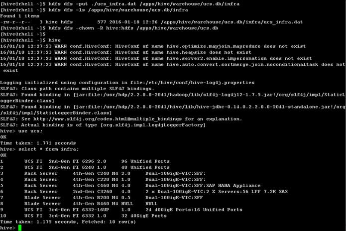
Install Spark Controller
1. SAP HANA Spark Controller RPM package from from the SAP Service Market Place https://websmp201.sap-ag.de/ and copy it over to the /tmp directory of the admin node (rhel1).

2. Install the SAP HANA Spark Controller using the following command.
rpm –ivh /tmp/sap.hana.spark.controller-1.5.4-1.noarch.rpm
3. Verify the correctness of the installation by listing the files in the directory /usr/sap/spark/controller. The folder structure should be similar to the below picture.
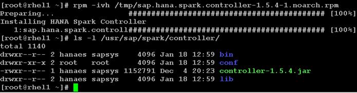
Download and Setup the Library Files Necessary to Configure Spark Controller on the HDFS
1. Create a directory called spark-controller in the /tmp directory of the admin node (rhel1).
mkdir /tmp/spark-controller
2. Download the following files from the respective locations as specified in the table below and copy them over to the /tmp/spark-controller directory of the admin node.
| File Name |
File location |
| spark-assembly-1.4.1-hadoop2.6.0.jar |
rhel1:/$SPARK_HOME/lib |
| spark-1.4.1-yarn-shuffle.jar |
rhel1:/$SPARK_HOME/lib |
3. Download the following Hadoop 3rd Party Files from the specified URLs. The Spark release 1.4.1 contain some of these files, but they are outdated.
| File Name |
File location |
| datanucleus-api-jdo-4.0.4.jar |
|
| datanucleus-core-4.0.4.jar |
http://central.maven.org/maven2/org/datanucleus/datanucleus-core/4.0.4/datanucleus-core-4.0.4.jar |
| datanucleus-rdbms-4.0.7.jar |
http://central.maven.org/maven2/org/datanucleus/datanucleus-rdbms/4.0.7/datanucleus-rdbms-4.0.7.jar |
| joda-time-2.3.jar |
http://central.maven.org/maven2/joda-time/joda-time/2.3/joda-time-2.3.jar |
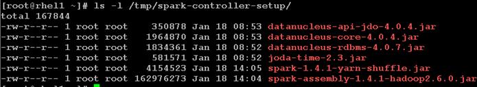
![]() It is important to download the correct version of these 3rd Hadoop 3rd party files for the correct operation of the Spark controller.
It is important to download the correct version of these 3rd Hadoop 3rd party files for the correct operation of the Spark controller.
1. Logon as hdfs user.
2. Create new directories on HDFS i.e. /sap/hana/spark/libs/thirdparty.
3. Copy over the /tmp/spark-controller-setup/spark-assembly-1.4.1-hadoop2.6.0.jar file to /sap/hana/spark/libs director on the HDFS.
4. Copy over the datanucleus-*.jar and joda-time-*.jar files to /sap/hana/spark/libs/thirdparty directory on the HDFS.
sudo -iu hdfs
hdfs dfs -mkdir -p /sap/hana/spark/libs
hdfs dfs -mkdir -p /sap/hana/spark/libs/thirdparty
![]()
hdfs dfs -put /tmp/spark-controller-setup/spark-assembly-1.4.1-hadoop2.6.0.jar /sap/hana/spark/libs/
hdfs dfs -put /tmp/spark-controller-setup/datanucleus-* /sap/hana/spark/libs/thirdparty/
hdfs dfs -put /tmp/spark-controller-setup/joda-* /sap/hana/spark/libs/thirdparty/
hdfs dfs -ls /sap/hana/spark/libs/thirdparty/
hdfs dfs -ls /sap/hana/spark/libs/
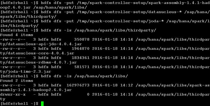
5. Create a staging/cache directory on the HDFS to be used by the Spark Controller.
6. Adjust the privileges to 666.
hdfs dfs -mkdir /user/hanaes
hdfs dfs -chmod 666 /user/hanaes
![]()
Configure the SAP HANA Spark Controller
1. Log onto the admin node (rhel1) which is also the Spark Controller node.
2. Start another shell as the user hanaes.
sudo -iu hanaes
![]() The user hanaes was automatically created by the Spark Controller installer program that was executed in the previous step.
The user hanaes was automatically created by the Spark Controller installer program that was executed in the previous step.
3. Verify the HDP version by listing the directory “/usr/hdp/2.2<TAB>” – using the TAB in the keyboard. Take a note of the actual HDP version.

4. Navigate to the Hana Spark Controller’s configuration directory.
5. Edit the hanaes-site.xml configuration file, and modify the hostname tag to match the hostname of the admin node (which is also the Spark Controller node).
6. Update the XML tags of spark.yarn.am.extraJavaOptions and spark.driver.extraJavaOptions to reflect the actual HDP version.
7. Add the property “spark.executor.memory” and set its value as 2g.
8. Since, there are 30 Vora worker nodes, choose the maxExecutors to be 600 (i.e. planning to allocate about 20 executors per server).
![]() The spark.executor.memory, minExectors and maxExecutors properties can be tuned further based on iterative testing.
The spark.executor.memory, minExectors and maxExecutors properties can be tuned further based on iterative testing.
cd /usr/sap/hana/spark/controller/conf
vi hanaes-site.xml
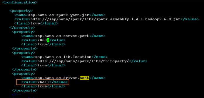
![]() The ports 7860, 7861 and 56000-58000 should be kept open in the Spark Controller (admin node) and. The port 7860 and 7861 are the SAP HANA Spark Controller ports. Ports 56000 to 58000 should be kept open on the servers where the Spark executors reside.
The ports 7860, 7861 and 56000-58000 should be kept open in the Spark Controller (admin node) and. The port 7860 and 7861 are the SAP HANA Spark Controller ports. Ports 56000 to 58000 should be kept open on the servers where the Spark executors reside.
9. Add the following configurations to allow the SAP HANA Spark Controller to discover the Vora hosts and the ZooKeeper hosts.
<property>
<name>spark.vora.hosts</name>
<value>rhel3:2202,rhel4:2202,rhel5:2202,rhel6:2202,rhel7:2202,rhel8:2202,rhel9:2202,rhel10:2202,rhel11:2202,rhel12:2202,rhel13:2202,rhel14:2202,rhel15:2202,rhel16:2202,rhel17:2202,rhel18:2202,rhel19:2202,rhel20:2202,rhel21:2202,rhel22:2202,rhel23:2202,rhel24:2202,rhel25:2202,rhel26:2202,rhel27:2202,rhel28:2202,rhel29:2202,rhel30:2202,rhel31:2202,rhel32:2202</value>
<final>true</final>
</property>
<property>
<name>spark.vora.zkurls</name>
<value>rhel1:2181,rhel2:2181,rhel3:2182</value>
<final>true</final>
</property>

10. Save the file hanaes-site.xml.
Configure Hive to be used with the Spark Controller
1. As a “root” user, copy over the hive-site.xml file from the /usr/hdp/2.2.<version>hive/conf/ over to /usr/sap/spark/controller/conf directory.
2. Change the ownership to hanaes:sapsys.
3. Switch user to hanaes.
cd /usr/sap/spark/controller/conf
cp /usr/hdp/2.2.0.0-2041/hive/conf/hive-site.xml .
chown hanaes:sapsys hive-site.xml

4. Edit the file and modify the following settings.
5. Parameter: hive.metastore.client.connect.retry.delay – change the value from 5s to 5
6. Parameter: hive.metastore.client.socket.timeout – change the value from 1800s to 1800
7. Parameter: hive.security.authorization.manager – change the value to org.apache.hadoop.hive.ql.security.authorization.DefaultHiveAuthorizationProvider
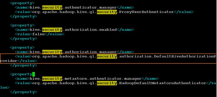
8. Parameter: hive.execution.engine – ensure that the value is set to “mr”.

![]() SAP HANA Spark Controller doesn’t support “tez” as a hive execution engine.
SAP HANA Spark Controller doesn’t support “tez” as a hive execution engine.
9. As the root user, copy over the YARN-shuffle jar file from the /tmp/spark-controller-setup directory to “hadoop-yarn/lib” directory in all the nodes using the following commands.
clush -a -c /tmp/spark-controller-setup/spark-1.4.1-yarn-shuffle.jar –dest= /usr/hdp/2.2.0.0-2041/hadoop-yarn/lib/
clush –a –B ls –l /usr/hdp/2.2.0.0-2041/hadoop-yarn/lib/spark-*
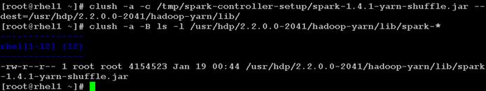
Update MapReduce and YARN configurations in Ambari
1. Log onto Ambari as the admin user.
2. Click on MapReduce on the Navigation Pane.
3. Click on the Config Tab in the work area.
4. Type “classpath” in the Property filter option.
5. Edit the property mapreduce.application.classpath property. In the field, replace all occurrences to “${hdp.version}” substring with the actual HDP version (in this particular installation it is 2.2.0.0-2041).
| Original String |
$PWD/mr-framework/hadoop/share/hadoop/mapreduce/*:$PWD/mr-framework/hadoop/share/hadoop/mapreduce/lib/*:$PWD/mr-framework/hadoop/share/hadoop/common/*:$PWD/mr-framework/hadoop/share/hadoop/common/lib/*:$PWD/mr-framework/hadoop/share/hadoop/yarn/*:$PWD/mr-framework/hadoop/share/hadoop/yarn/lib/*:$PWD/mr-framework/hadoop/share/hadoop/hdfs/*:$PWD/mr-framework/hadoop/share/hadoop/hdfs/lib/*:/usr/hdp/${hdp.version}/hadoop/lib/hadoop-lzo-0.6.0.${hdp.version}.jar:/etc/hadoop/conf/secure |
| Modified String |
$PWD/mr-framework/hadoop/share/hadoop/mapreduce/*:$PWD/mr-framework/hadoop/share/hadoop/mapreduce/lib/*:$PWD/mr-framework/hadoop/share/hadoop/common/*:$PWD/mr-framework/hadoop/share/hadoop/common/lib/*:$PWD/mr-framework/hadoop/share/hadoop/yarn/*:$PWD/mr-framework/hadoop/share/hadoop/yarn/lib/*:$PWD/mr-framework/hadoop/share/hadoop/hdfs/*:$PWD/mr-framework/hadoop/share/hadoop/hdfs/lib/*:/usr/hdp/2.2.0.0-2041/hadoop/lib/hadoop-lzo-0.6.0.2.2.0.0-2041.jar:/etc/hadoop/conf/secure |
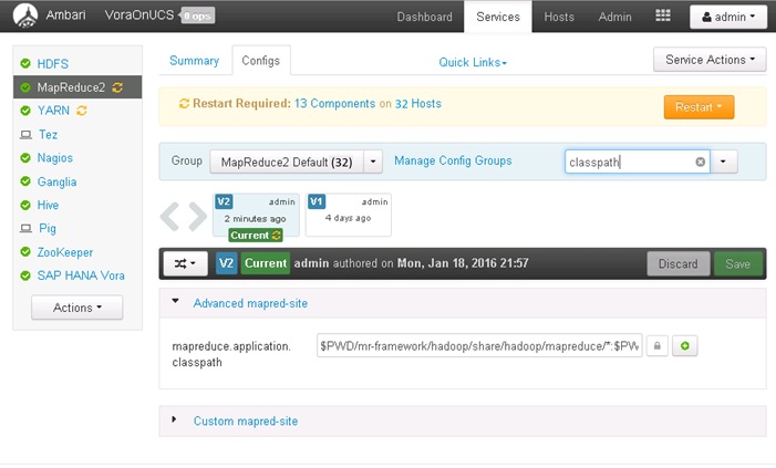
6. Click <Save> to apply the changes.
7. Click on YARN in the navigation pane.
8. Click on Config to edit the configurations.
9. Enter “aux-services” in the Filter
10. Edit the property “mapreduce.nodemanager.aux-services” to add the string “spark_shuffle”. The resulting string should be “mapreduce_shuffle,spark_shuffle” as shown below.
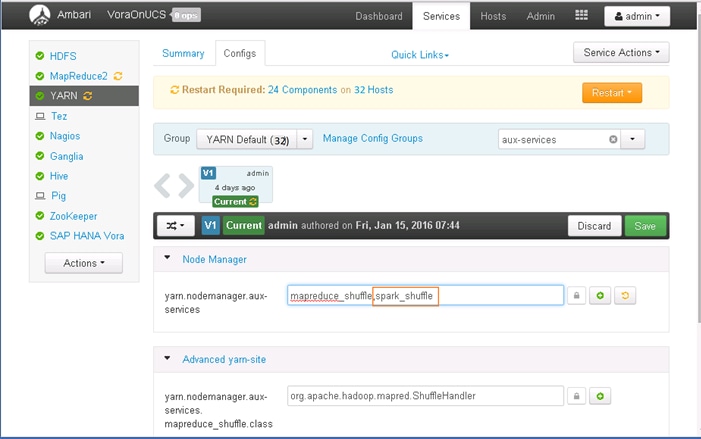
11. Click <Save> to save the changes.
12. Scroll all the way to the end of the YARN configuration to add a custom property to the section “Custom yarn-site”.
13. Click on “Add property”.
14. Enter the Key “yarn.nodemanager.aux-services.spark_shuffle.class” and value as “org.apache.spark.network.yarn.YarnShuffleService”. Click Add to add the new property.
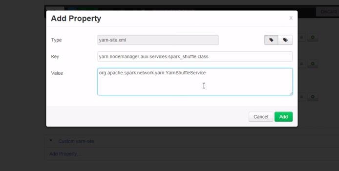
15. Click Save to save the configuration. Provide an appropriate description of the change i.e. Shuffle class selection to keep track of the configuration version.
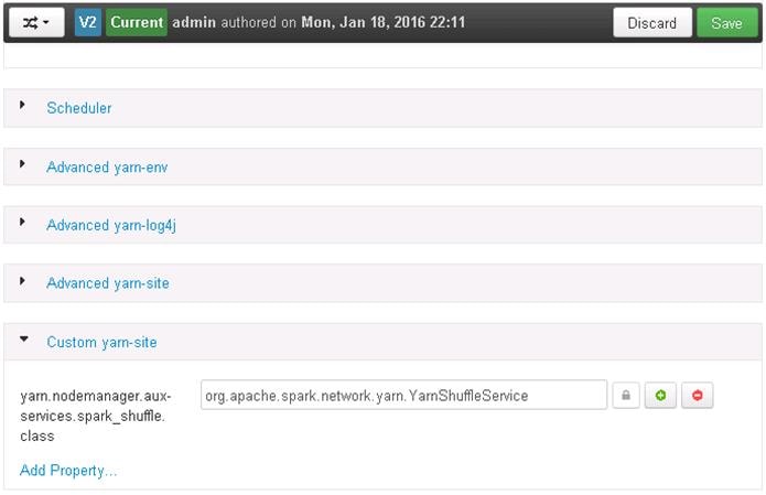
16. Restart YARN and MapReduce2 services.
Start hanaes Service
1. Log onto the admin node (rhel1), which is also the Spark Controller host as the root user.
2. Copy over the file “spark-sap-datasources-*-assembly.jar from /home/vora/vora/lib directory to /usr/sap/spark/controller/lib directory.
3. Change the ownership of the file at the destination to user hanaes:sapsys.
cd /usr/sap/spark/controller/lib
cp /home/vora/vora/lib/spark-sap-datasources-1.1.40-assembly.jar .
chown hanaes:sapsys ./spark-sap-datasources-1.1.40-assembly.jar
ls -l
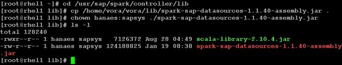
4. Switch the user to hanaes.
5. Change directory to /usr/sap/spark/controller/bin.
6. Start the hanaes service as below, and observe the logs.
sudo -iu hanaes
cd /usr/sap/spark/controller/bin
./hanaes start
tail -f /var/log/hanaes/hanaes_controller.log
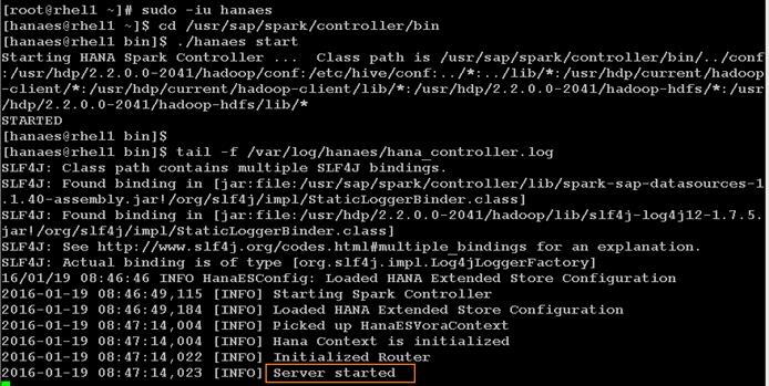
At this point, the SAP HANA Spark controller is up and running. This service will facilitate the SAP HANA to access the data available in the SAP HANA Vora cluster. This facilitates use cases such as Data Life Cycle management and business analytics.
For more information please refer to https://help.sap.com/hana_vora_re and documentation about SAP HANA Data Warehousing Foundation.
This section gives the BOM for the 160 node Performance Optimized Cluster.
Table 6 Bill of Materials for C240M4SX Base Rack
| Part Number |
Description |
Quantity |
| UCS-SL-CPA3-P |
Performance Optimized Cluster |
1 |
| UCSC-C240-M4SX |
UCS C240 M4 SFF 24 HD w/o CPU, mem, HD, PCIe, PS, railkt w/expndr |
16 |
| UCSC-MRAID12G |
Cisco 12G SAS Modular Raid Controller |
16 |
| UCSC-MRAID12G-2GB |
Cisco 12Gbps SAS 2GB FBWC Cache module (Raid 0/1/5/6) |
16 |
| UCSC-MLOM-CSC-02 |
Cisco UCS VIC1227 VIC MLOM - Dual Port 10Gb SFP+ |
16 |
| CAB-9K12A-NA |
Power Cord 125VAC 13A NEMA 5-15 Plug North America |
32 |
| UCSC-PSU2V2-1200W |
1200W V2 AC Power Supply for 2U C-Series Servers |
32 |
| UCSC-RAILB-M4 |
Ball Bearing Rail Kit for C220 M4 and C240 M4 rack servers |
16 |
| UCSC-HS-C240M4 |
Heat Sink for UCS C240 M4 Rack Server |
32 |
| UCSC-SCCBL240 |
Supercap cable 250mm |
16 |
| UCS-CPU-E52680D |
2.50 GHz E5-2680 v3/120W 12C/30MB Cache/DDR4 2133MHz |
32 |
| UCS-MR-1X162RU-A |
16GB DDR4-2133-MHz RDIMM/PC4-17000/dual rank/x4/1.2v |
256 |
| UCS-HD12T10KS2-E |
1.2 TB 6G SAS 10K rpm SFF HDD |
384 |
| UCS-SD120G0KSB-EV |
120 GB 2.5 inch Enterprise Value 6G SATA SSD (BOOT) |
32 |
| UCSC-PCI-1C-240M4 |
Right PCI Riser Bd (Riser 1) 2onbd SATA bootdrvs+ 2PCI slts |
16 |
| UCS-FI-6296UP-UPG |
UCS 6296UP 2RU Fabric Int/No PSU/48 UP/ 18p LIC |
2 |
| CON-SNT-FI6296UP |
SMARTNET 8X5XNBD UCS 6296UP 2RU Fabric Int/2 PSU/4 Fans |
2 |
| SFP-H10GB-CU3M |
10GBASE-CU SFP+ Cable 3 Meter |
60 |
| UCS-ACC-6296UP |
UCS 6296UP Chassis Accessory Kit |
2 |
| UCS-PSU-6296UP-AC |
UCS 6296UP Power Supply/100-240VAC |
4 |
| N10-MGT012 |
UCS Manager v2.2 |
2 |
| UCS-L-6200-10G-C |
2rd Gen FI License to connect C-direct only |
108 |
| UCS-BLKE-6200 |
UCS 6200 Series Expansion Module Blank |
6 |
| UCS 6296UP Fan Module |
UCS 6296UP Fan Module |
8 |
| CAB-N5K6A-NA |
Power Cord 200/240V 6A North America |
4 |
| UCS-FI-E16UP |
UCS 6200 16-port Expansion module/16 UP/ 8p LIC |
6 |
| RACK-UCS2 |
Cisco R42610 standard rack w/side panels |
1 |
| RP208-30-1P-U-2= |
Cisco RP208-30-U-2 Single Phase PDU 20x C13 4x C19 (Country Specific) |
2 |
| CON-UCW3-RPDUX |
UC PLUS 24X7X4 Cisco RP208-30-U-X Single Phase PDU 2x |
6 |
Optional Base Rack Materials
| UCS-SD480G0KSB-EV |
480 GB 2.5 inch Enterprise Value 6G SATA SSD (BOOT) |
32 |
Table 7 Bill of Materials for Expansion Racks
| Part Number |
Description |
Quantity |
| UCSC-C240-M4SX |
UCS C240 M4 SFF 24 HD w/o CPU, mem, HD, PCIe, PS, railkt w/expndr |
16 |
| UCSC-MRAID12G |
Cisco 12G SAS Modular Raid Controller |
16 |
| UCSC-MRAID12G-2GB |
Cisco 12Gbps SAS 2GB FBWC Cache module (Raid 0/1/5/6) |
16 |
| UCSC-MLOM-CSC-02 |
Cisco UCS VIC1227 VIC MLOM - Dual Port 10Gb SFP+ |
16 |
| CAB-9K12A-NA |
Power Cord 125VAC 13A NEMA 5-15 Plug North America |
32 |
| UCSC-PSU2V2-1200W |
1200W V2 AC Power Supply for 2U C-Series Servers |
32 |
| UCSC-RAILB-M4 |
Ball Bearing Rail Kit for C220 M4 and C240 M4 rack servers |
16 |
| UCSC-HS-C240M4 |
Heat Sink for UCS C240 M4 Rack Server |
32 |
| UCSC-SCCBL240 |
Supercap cable 250mm |
16 |
| UCS-CPU-E52680D |
2.50 GHz E5-2680 v3/120W 12C/30MB Cache/DDR4 2133MHz |
32 |
| UCS-MR-1X162RU-A |
16GB DDR4-2133-MHz RDIMM/PC4-17000/dual rank/x4/1.2v |
256 |
| UCS-HD12T10KS2-E |
1.2 TB 6G SAS 10K rpm SFF HDD |
384 |
| UCS-SD120G0KSB-EV |
120 GB 2.5 inch Enterprise Value 6G SATA SSD (BOOT) |
32 |
| UCSC-PCI-1C-240M4 |
Right PCI Riser Bd (Riser 1) 2onbd SATA bootdrvs+ 2PCI slts |
16 |
Optional Expansion Rack Materials
| UCS-SD480G0KSB-EV |
480 GB 2.5 inch Enterprise Value 6G SATA SSD (BOOT) |
32 |
| RACK-UCS2 |
||
| RP208-30-1P-U-2= |
Cisco RP208-30-U-2 Single Phase PDU 20x C13 4x C19 (Country Specific) |
|
| CON-UCW3-RPDUX |
UC PLUS 24X7X4 Cisco RP208-30-U-X Single Phase PDU 2x (Country Specific) |
Table 8 Red Hat Enterprise Linux License
| Red Hat Enterprise Linux |
||
| RHEL-2S-1G-3A |
Red Hat Enterprise Linux |
32 |
| CON-ISV1-RH2S1G3A |
3 year Support for Red Hat Enterprise Linux |
32 |
Table 9 Bill of Materials for Nexus Device and APIC
| Part Number |
Description |
Quantity |
| N9K-C9508-B2 |
Nexus 9508 Chassis Bundle with 1 Sup, 3 PS, 2 SC, 6 FM, 3 FT |
2 |
| N9K-C9396PX |
Nexus 9300 with 48p 1/10G SFP+ and 1 uplink module slot |
2 |
| N9k-X9736PQ |
Spine Line-Card |
2 |
| APIC-L1 |
APIC Appliance |
3 |
| N9K POWERCABLES |
Power Cables |
3 |
| CAB-C13-C14-AC |
Power cord, C13 to C14 (recessed receptacle), 10A |
4 |
| QSFP-H40G-CU3M |
40GBASE-CR4 Passive Copper Cable, 3m |
24 |
| Nexus 9372TX |
Nx-OS mode switch for out of band Management |
1 |
| N9K-M12PQ |
ACI Uplink Module for Nexus 9300, 12p 40G QSFP |
3 |
| N9K-C9500-RMK |
Nexus 9500 Rack Mount Kit |
2 |
| CAB-C19-CBN |
Cabinet Jumper Power Cord, 250 VAC 16A, C20-C19 Connectors |
6 |
| N9K-C9500-LC-CV |
Nexus 9500 Linecard slot cover |
16 |
| N9K-C9500-SUP-CV |
Nexus 9500 Supervisor slot cover |
2 |
| N9K-PAC-3000W-B |
Nexus 9500 3000W AC PS, Port-side Intake |
6 |
| N9K-SUP-A |
Supervisor for Nexus 9500 |
2 |
| N9K-SC-A |
System Controller for Nexus 9500 |
4 |
| N9K FABRIC |
Fabric Module |
2 |
| N9300 RACK |
Rack Mount Kit |
3 |
| N9K-C9300-RMK |
Nexus 9300 Rack Mount Kit |
3 |
Hadoop has become a popular data management platform across all verticals. Cisco UCS Integrated Infrastructure for Big Data and Cisco Application Centric Infrastructure (ACI) offers a dependable deployment model for enterprise Hadoop, Apache Spark and SAP HANA Vora that offer a fast and predictable path for businesses to unlock value in big data. This architecture allows using the UCS Manager capabilities in Fabric Interconnect for provisioning the servers within a single domain while providing a facility to interconnect multiple Fabric Interconnect domains with ACI. Up to 80 servers (5 racks) can be supported with no additional switching in a single UCS domain with no network over-subscription.
Cisco solutions continue a long history of delivering innovative IT infrastructure for SAP landscapes with certified reference architectures that reduce cost and risk. The entire family of solutions—for SAP Applications, SAP HANA, and now SAP HANA Vora—is designed to interoperate with the data center you have today. Cisco solutions use industry-standard architectures and best practices, so no special IT processes are needed to incorporate or maintain the solutions in your data center.
The configuration detailed in the document can be extended to clusters of various sizes depending on what application demands as discussed in the Scalability section. Next generation Big Data Infrastructure needs to cater to the emerging trends in Big Data Applications to meet multiple Lines of Business (LOB) SLAs. Cisco UCS Integrated Infrastructure for Big Data and Cisco ACI brings numerous advantages to a Big Data cluster – fewer point of management for the network, enhanced performance, superior failure handling characteristics, unprecedented scalability. Further, ACI paves way to the next generation data center network accelerating innovation with its SDN capabilities in the Big Data space.
· Cisco Big Data design zone: http://www.cisco.com/go/bigdata_design
· SAP HANA Vora Community Network: https://help.sap.com/hana_vora_re
· Cisco SAP Solutions: http://www.cisco.com/go/sap
· Cisco ACI: http://www.cisco.com/go/aci
Karthik Karupasamy is a Technical Marketing Engineer in the Data Center Solutions Group at Cisco Systems. His main focus areas are architecture, solutions, and emerging trends in big data related technologies and infrastructure in the Data Center.
Tim Berning is a Software Engineer at SAP. He is one of the core developers on the SAP HANA Vora engineering team.
Acknowledgement
Amrit Kharel, System Engineer, Cisco Systems, Inc.
Karthik Kulkarni, Technical Marketing Engineer, Cisco Systems, Inc.
Barbara Dixon, Technical Writer, Cisco Systems, Inc.
 Feedback