Cisco UCS Common Platform Architecture (CPA) for Big Data with Hortonworks
Available Languages
Table Of Contents
About Cisco Validated Design (CVD) Program
Cisco UCS Common Platform Architecture (CPA) for Big Data with Hortonworks
Cisco UCS Common Platform Architecture for Big Data
Hortonworks Data Platform (HDP)
Hortonworks - Key Features and Benefits
Server Configuration and Cabling
Software Distributions and Versions
Hortonworks Data Platform (HDP)
Performing Initial Setup of Cisco UCS 6296 Fabric Interconnects
Configure Fabric Interconnect A
Configure Fabric Interconnect B
Logging Into Cisco UCS Manager
Upgrading UCSM Software to Version 2.1(1e)
Adding Block of IP Addresses for KVM Access
Editing The Chassis Discovery Policy
Enabling The Server Ports and Uplink Ports
Creating Pools for Service Profile Templates
Creating Policies for Service Profile Templates
Creating a Host Firmware Package Policy
Creating the Best Effort Policy
Creating a Local Disk Configuration Policy
Creating a Service Profile Template
Configuring the Network Settings for the Template
Configuring a Storage Policy for the Template
Configuring a vNIC/vHBA Placement for the Template
Configuring a Server Boot Order for the Template
Configuring Server Assignment for the Template
Configuring Operational Policies for the Template
Configuring Disk Drives for Operating System on NameNode
Configuring Disk Drives for Operating System on DataNodes
Installing Red Hat Linux 6.2 with KVM
Setting Up Password-less Login
Installing and Configuring Parallel SSH
Creating Red Hat Local Repository
Download Java SE 6 Development Kit (JDK)
Configuring Data Drives on NameNode
Configuring the Filesystem for NameNodes
Configuring Data Drives on DataNodes
Configuring the Filesystem for DataNodes
Prerequisites for HDP Installation
Install and Setup Ambari Server on rhel1
Configure Ambari Server to use Local Repository
Summary of Installation Process
Cisco UCS Common Platform Architecture (CPA) for Big Data with HortonworksBuilding a 64-Node Hadoop ClusterLast Updated: October 25, 2013

Building Architectures to Solve Business Problems
About the Authors
Raghunath Nambiar, Cisco SystemsRaghunath Nambiar is a Distinguished Engineer at Cisco's Data Center Business Group. His current responsibilities include emerging technologies and big data strategy.
Ajay Singh, HortonworksAjay Singh is Director, Technology Alliances at Hortonworks. Ajay is responsible for design & validation of ecosystem solutions to optimally integrate, deploy & operate Hortonworks Data Platform.
Manankumar Trivedi, Cisco SystemsManan is a member of the solution engineering team focusing on big data infrastructure and performance. He holds masters of science degree from Stratford University.
Karthik Kulkarni, Cisco SystemsKarthik Kulkarni is a Technical Marketing Engineer at Cisco Data Center Business Group focusing on Big Data and Hadoop technologies.
Acknowledgment
The authors acknowledge contributions of Ashwin Manjunatha, and Sindhu Sudhir in developing the Cisco UCS Common Platform Architecture (CPA) for Big Data with Hortonworks Cisco Validated Design.
About Cisco Validated Design (CVD) Program
The CVD program consists of systems and solutions designed, tested, and documented to facilitate faster, more reliable, and more predictable customer deployments. For more information visit:
http://www.cisco.com/go/designzone
ALL DESIGNS, SPECIFICATIONS, STATEMENTS, INFORMATION, AND RECOMMENDATIONS (COLLECTIVELY, "DESIGNS") IN THIS MANUAL ARE PRESENTED "AS IS," WITH ALL FAULTS. CISCO AND ITS SUPPLIERS DISCLAIM ALL WARRANTIES, INCLUDING, WITHOUT LIMITATION, THE WARRANTY OF MERCHANTABILITY, FITNESS FOR A PARTICULAR PURPOSE AND NONINFRINGEMENT OR ARISING FROM A COURSE OF DEALING, USAGE, OR TRADE PRACTICE. IN NO EVENT SHALL CISCO OR ITS SUPPLIERS BE LIABLE FOR ANY INDIRECT, SPECIAL, CONSEQUENTIAL, OR INCIDENTAL DAMAGES, INCLUDING, WITHOUT LIMITATION, LOST PROFITS OR LOSS OR DAMAGE TO DATA ARISING OUT OF THE USE OR INABILITY TO USE THE DESIGNS, EVEN IF CISCO OR ITS SUPPLIERS HAVE BEEN ADVISED OF THE POSSIBILITY OF SUCH DAMAGES.
THE DESIGNS ARE SUBJECT TO CHANGE WITHOUT NOTICE. USERS ARE SOLELY RESPONSIBLE FOR THEIR APPLICATION OF THE DESIGNS. THE DESIGNS DO NOT CONSTITUTE THE TECHNICAL OR OTHER PROFESSIONAL ADVICE OF CISCO, ITS SUPPLIERS OR PARTNERS. USERS SHOULD CONSULT THEIR OWN TECHNICAL ADVISORS BEFORE IMPLEMENTING THE DESIGNS. RESULTS MAY VARY DEPENDING ON FACTORS NOT TESTED BY CISCO.
CCDE, CCENT, Cisco Eos, Cisco Lumin, Cisco Nexus, Cisco StadiumVision, Cisco TelePresence, Cisco WebEx, the Cisco logo, DCE, and Welcome to the Human Network are trademarks; Changing the Way We Work, Live, Play, and Learn and Cisco Store are service marks; and Access Registrar, Aironet, AsyncOS, Bringing the Meeting To You, Catalyst, CCDA, CCDP, CCIE, CCIP, CCNA, CCNP, CCSP, CCVP, Cisco, the Cisco Certified Internetwork Expert logo, Cisco IOS, Cisco Press, Cisco Systems, Cisco Systems Capital, the Cisco Systems logo, Cisco Unity, Collaboration Without Limitation, EtherFast, EtherSwitch, Event Center, Fast Step, Follow Me Browsing, FormShare, GigaDrive, HomeLink, Internet Quotient, IOS, iPhone, iQuick Study, IronPort, the IronPort logo, LightStream, Linksys, MediaTone, MeetingPlace, MeetingPlace Chime Sound, MGX, Networkers, Networking Academy, Network Registrar, PCNow, PIX, PowerPanels, ProConnect, ScriptShare, SenderBase, SMARTnet, Spectrum Expert, StackWise, The Fastest Way to Increase Your Internet Quotient, TransPath, WebEx, and the WebEx logo are registered trademarks of Cisco Systems, Inc. and/or its affiliates in the United States and certain other countries.
All other trademarks mentioned in this document or website are the property of their respective owners. The use of the word partner does not imply a partnership relationship between Cisco and any other company. (0809R)
© 2013 Cisco Systems, Inc. All rights reserved.
Cisco UCS Common Platform Architecture (CPA) for Big Data with Hortonworks
Audience
This document describes the architecture and deployment procedures of Hortonworks Data Platform (HDP) on a 64 node cluster based Cisco UCS Common Platform Architecture (CPA) for Big Data. The intended audience of this document includes, but is not limited to, sales engineers, field consultants, professional services, IT managers, partner engineering and customers who want to deploy HDP on the Cisco UCS CPA for Big Data.
Introduction
Hadoop has become a strategic data platform embraced by mainstream enterprises as it offers the fastest path for businesses to unlock value in big data while maximizing existing investments. The Hortonworks Data Platform (HDP) is a 100% open source distribution of Apache Hadoop that is truly enterprise grade having been built, tested and hardened with enterprise rigor. The combination of HDP and Cisco UCS provides industry-leading platform for Hadoop based applications.
Cisco UCS Common Platform Architecture for Big Data
The Cisco UCS solution for HDP is based on Cisco Common Platform Architecture (CPA) for Big Data, a highly scalable architecture designed to meet a variety of scale-out application demands with seamless data integration and management integration capabilities built using the following components:
•
Cisco UCS 6200 Series Fabric Interconnects—provide high-bandwidth, low-latency connectivity for servers, with integrated, unified management provided for all connected devices by Cisco UCS Manager. Deployed in redundant pairs, Cisco fabric interconnects offer the full active-active redundancy, performance, and exceptional scalability needed to support the large number of nodes that are typical in clusters serving Big Data applications. Cisco UCS Manager enables rapid and consistent server configuration using service profiles and automation of the ongoing system maintenance activities such as firmware updates across the entire cluster as a single operation. Cisco UCS Manager also offers advanced monitoring with options to raise alarms and send notifications about the health of the entire cluster.
•
•
•
•
Hortonworks Data Platform (HDP)
The Hortonworks Data Platform (HDP) is an enterprise-grade, hardened Apache Hadoop distribution that enables you to store, process, and manage large data sets.
Apache Hadoop is an open-source software framework that allows for the distributed processing of large data sets across clusters of computers using simple programming models. It is designed for high-availability and fault-tolerance, and can scale from a single server up to thousands of machines.
The Hortonworks Data Platform combines the most useful and stable versions of Apache Hadoop and its related projects into a single tested and certified package. Hortonworks offers the latest innovations from the open source community, along with the testing and quality you expect from enterprise-quality software.
The Hortonworks Data Platform is designed to integrate with and extend the capabilities of your existing investments in data applications, tools, and processes. With Hortonworks, you can refine, analyze, and gain business insights from both structured and unstructured data - quickly, easily, and economically.
Hortonworks - Key Features and Benefits
With the Hortonworks Data Platform, enterprises can retain and process more data, join new and existing data sets, and lower the cost of data analysis. Hortonworks enables enterprises to implement the following data management principles:
•
•
•
•
•
•
The Hortonworks Data Platform is the foundation for the next-generation enterprise data architecture - one that addresses both the volume and complexity of today's data.
Solution Overview
The current version of the Cisco UCS CPA for Big Data offers two options depending on the compute and storage requirements:
•
•

Note
The High Performance Cluster configuration consists of the following:
•
•
•
•
•
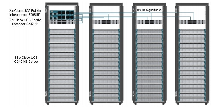
Rack and PDU Configuration
Each rack consists of two vertical PDU. The master rack consists of two Cisco UCS 6296UP Fabric Interconnects, two Cisco Nexus 2232PP Fabric Extenders and sixteen Cisco UCS C240M3 Servers, connected to each of the vertical PDUs for redundancy; thereby, ensuring availability during power source failure. The expansion racks also consists of two Cisco Nexus 2232PP Fabric Extenders and sixteen Cisco UCS C240M3 Servers are connected to each of the vertical PDUs for redundancy; thereby, ensuring availability during power source failure, similar to master rack.
Note
Table 1 and Table 2 describe the rack configurations of rack 1 (master rack) and racks 2-4 (expansion racks).
Table 2 Rack Configuration for the Expansion Rack (Racks 2-4)
Server Configuration and Cabling
The Cisco UCS C240M3 Rack Server is equipped with Intel Xeon E5-2665 processors, 256 GB of memory, Cisco UCS Virtual Interface Card (VIC)1225, LSI MegaRAID SAS 9266-8i storage controller and 24 x 1TB 7.2K Serial Advance Technology Attachment (SATA) disk drives.
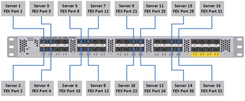
Figure 1 illustrates the ports on the Cisco Nexus 2232PP fabric extender connecting to the Cisco UCS C240M3 servers. Sixteen Cisco UCS C240M3 servers are used in the master rack configurations.
Figure 1 Fabric Topology
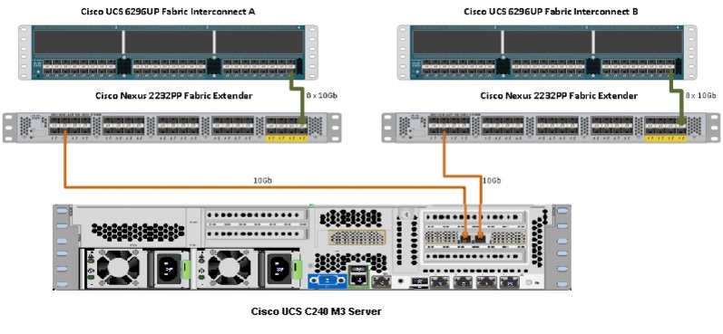
Figure 2 illustrates the port connectivity between the Cisco Nexus 2232PP FEX and the Cisco UCS C240M3 server.
Figure 2 Connectivity Diagram of Cisco Nexus 2232PP FEX and Cisco UCS C240M3 Servers
For more information on physical connectivity and single-wire management, see:
For more information on physical connectivity illustrations and cluster setup, see:
Figure 3 depicts a 64-node cluster, and each link represents 8 x 10 Gigabit link.
Figure 3 64 -Node Cluster Configuration
Software Distributions and Versions
Hortonworks Data Platform (HDP)
The Hortonworks Data Platform supported is HDP 1.3. For more information, see: http://www.hortonworks.com
RHEL
The Operating System supported is Red Hat Enterprise Linux Server 6.2. For more information on the Linux support, see:
Software Versions
Table 3 describes the software versions tested and validated in this document.
Note
Fabric Configuration
This section provides details for configuring a fully redundant, highly available Cisco UCS 6296 Fabric Interconnect.
1.
2.
3.
4.
5.
6.
7.
8.
9.
Performing Initial Setup of Cisco UCS 6296 Fabric Interconnects
This section describes the steps to perform the initial setup of the Cisco UCS 6296 Fabric Interconnects A and B.
Configure Fabric Interconnect A
Follow these steps to configure the Fabric Interconnect A:
1.
2.
3.
4.
5.
6.
7.
8.
9.
10.
11.
12.
13.
14.
15.
16.
17.
18.
19.
20.
Configure Fabric Interconnect B
Follow these steps to configure the Fabric Interconnect B:
1.
2.
3.
4.
5.
6.
7.
For more information on configuring Cisco UCS 6200 Series Fabric Interconnect, see:
Logging Into Cisco UCS Manager
Follow these steps to login to Cisco UCS Manager.
1.
2.
3.
4.
5.
Upgrading UCSM Software to Version 2.1(1e)
This document assumes the uses of Cisco UCS 2.1(1e). Make sure that the Cisco UCS C-Series version 2.1(1e) software bundle is installed on the Cisco UCS Fabric Interconnects.
To upgrade the Cisco UCS Manager software and Cisco UCS 6296 Fabric Interconnect software to version 2.1(1e), see: Upgrading Cisco UCS from Release 2.0 to Releases 2.1
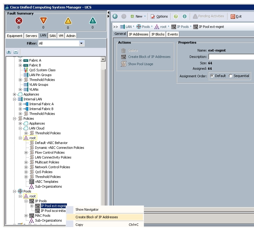
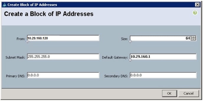
Adding Block of IP Addresses for KVM Access
Follow these steps to create a block of KVM IP addresses for the server access in Cisco UCS environment.
1.
2.
3.
4.
Figure 4 Adding Block of IP Addresses for KVM Access Part 1
5.
Figure 5 Adding Block of IP Addresses for KVM Access Part 2

6.
Figure 6 Adding Block of IP Addresses for KVM Access Part 3
7.
Editing The Chassis Discovery Policy
This section provides details for modifying the chassis discovery policy. Setting the discovery policy ensures easy addition of the Cisco UCS B-Series chassis or fabric extenders for the Cisco UCS C-Series servers in future.
1.
2.
3.
4.
Figure 7 Changing The Chassis Discovery Policy
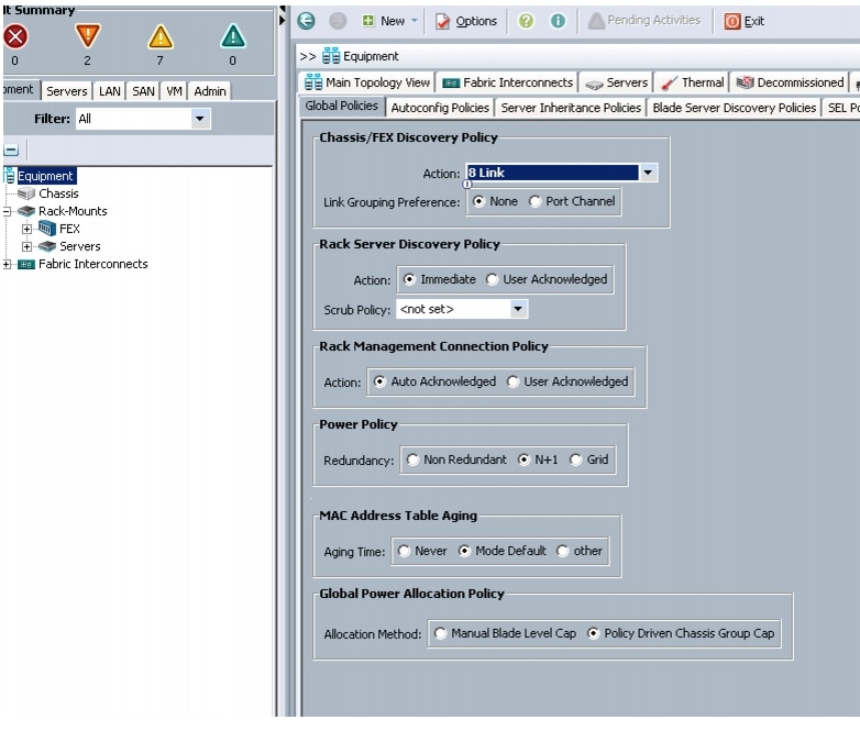
5.
6.
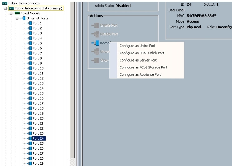
Enabling The Server Ports and Uplink Ports
Follow these steps to enable the server and configure the uplink ports:
1.
2.
3.
4.
5.
6.
7.
8.
9.
10.
11.
12.
Figure 8 Enabling Server Ports
13.
14.
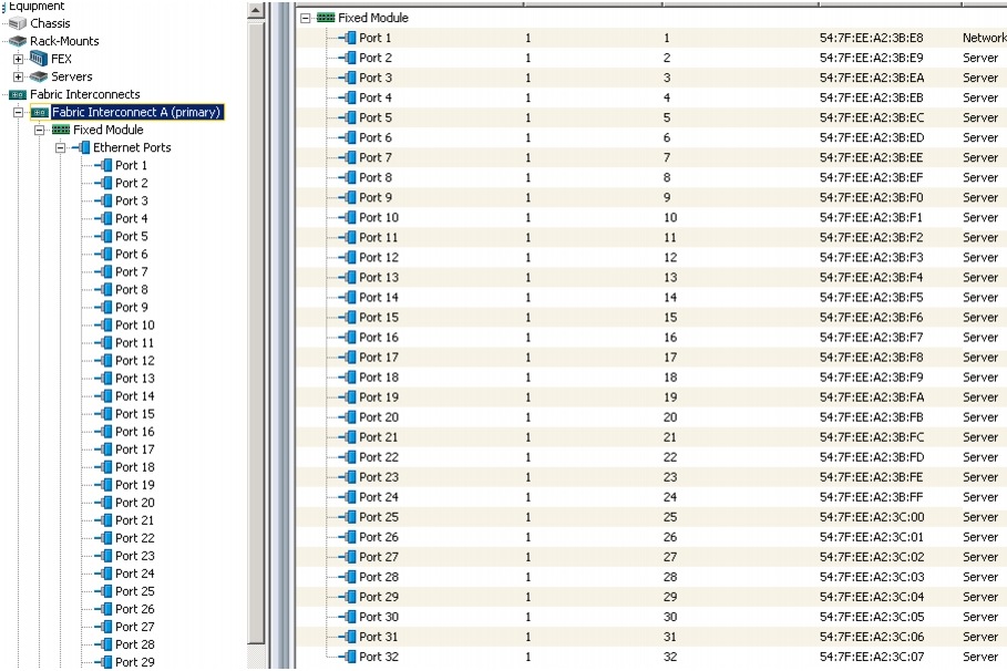
Figure 9 shows all the configured uplink and Server ports.
Figure 9 Server and Uplink Ports Summary
Creating Pools for Service Profile Templates
Creating an Organization
Organizations are used as a means to arrange and restrict access to various groups within the IT organization, and enable multi-tenancy of the compute resources. This document does not use organizations; however, the steps to create an organizations are given for future reference.
Follow these steps to configure an organization in the Cisco UCS Manager:
1.
2.
3.
4.
5.
Creating MAC Address Pools
Follow these steps to create MAC address pools:
1.
2.
3.
4.
5.
6.
7.
8.
9.
10.
Figure 10 Specifying the First MAC Address and Size
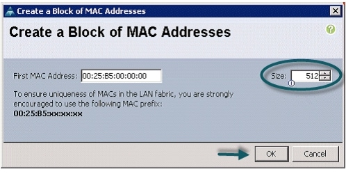
11.
Figure 11 Adding MAC Addresses
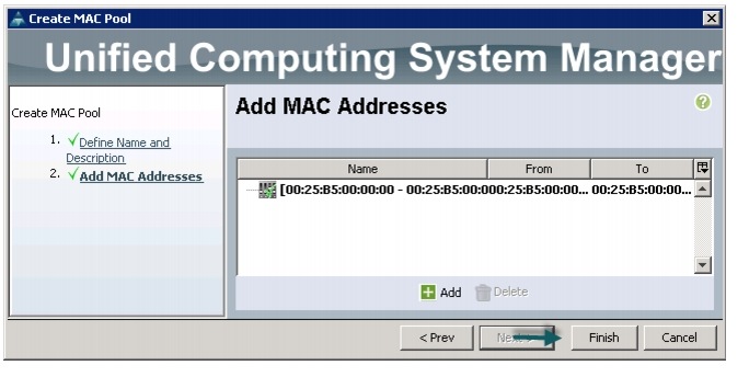
12.
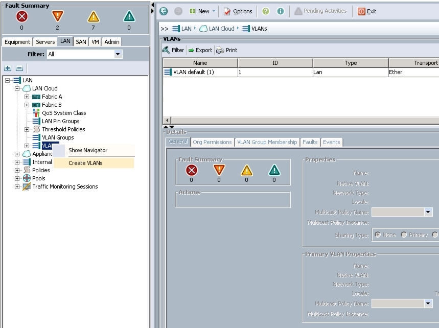
Configuring VLANs
Table 4 describes the VLANs that are configured in this design solution.
All of the VLANs created should be trunked to the upstream distribution switch connecting the fabric interconnects. In this deployment, vlan160_mgmt is configured for management access and user connectivity, vlan12_HDFS is configured for Hadoop interconnect traffic, and vlan11_DATA is configured for optional secondary interconnect and/or SAN/NAS access, heavy ETL, and so on.
Follow these steps to configure VLANs in Cisco UCS Manager:
1.
2.
3.
4.
Figure 12 Creating VLAN
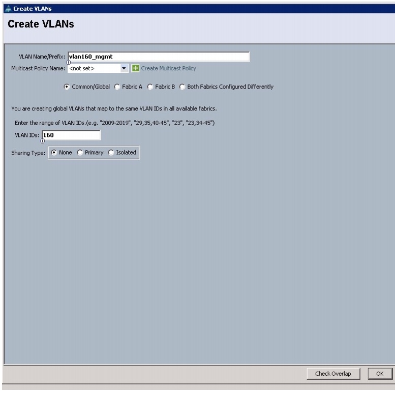
5.
6.
7.
8.
9.
Figure 13 Creating Management VLAN
10.
11.
12.
13.
14.
15.
16.
17.
18.
Figure 14 Creating VLAN for Data
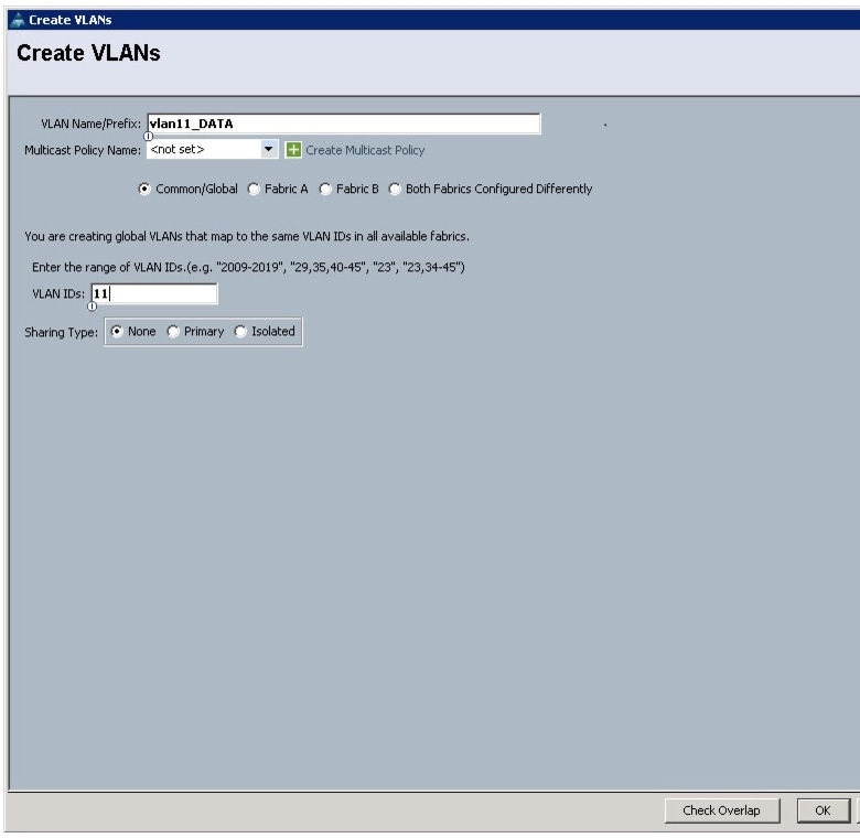
19.
20.
21.
22.
23.
24.
25.
26.
Figure 15 Creating VLAN for Hadoop Data

Creating a Server Pool
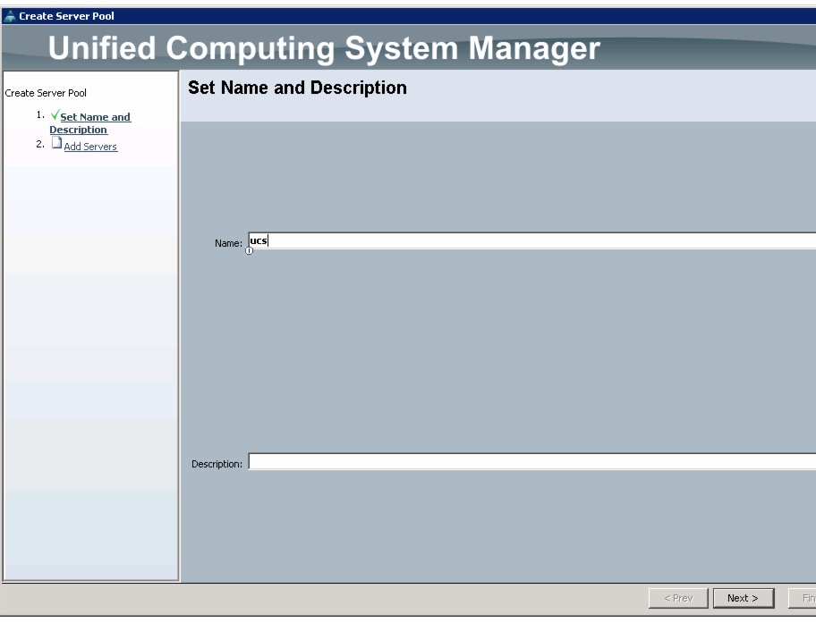
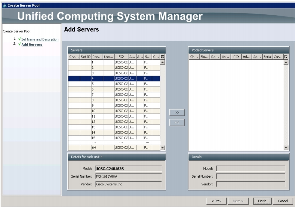
A server pool contains a set of servers. These servers typically share the same characteristics such as their location in the chassis, server type, amount of memory, local storage, type of CPU, or local drive configuration. You can manually assign a server to a server pool, or use the server pool policies and server pool policy qualifications to automate the server assignment.
Follow these steps to configure the server pool within the Cisco UCS Manager:
1.
2.
3.
4.
5.
6.
Figure 16 Setting Name and Description of the Server Pool
7.
8.
9.
Figure 17 Adding Servers to the Server Pool
Creating Policies for Service Profile Templates
This section provides you the procedure to create the following policies for the service profile template:
•
•
•
Creating a Host Firmware Package Policy
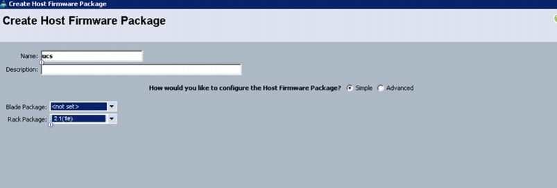
Firmware management policies allow the administrator to select the corresponding firmware packages for a given server configuration. The components that can be configured include adapters, BIOS, board controllers, FC adapters, HBA options, ROM and storage controller.
Follow these steps to create a host firmware management policy for a given server configuration using the Cisco UCS Manager:
1.
2.
3.
4.
5.
6.
7.
8.
9.
Figure 18 Creating Host Firmware Package
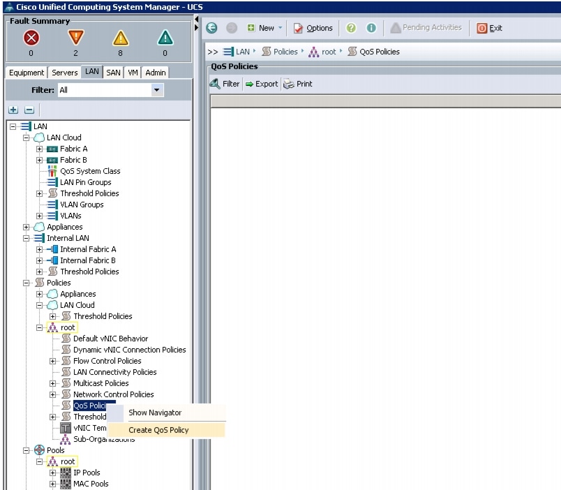
Creating QoS Policies
This section describes the procedure to create the Best Effort QoS Policy and Platinum QoS policy.
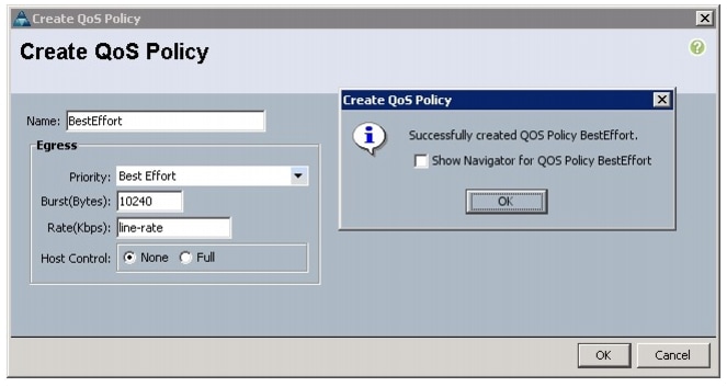
Creating the Best Effort Policy
Follow these steps to create the Best Effort Policy:
1.
2.
3.
4.
Figure 19 Creating QoS Policy
5.
6.
7.
8.
9.
10.
11.
Figure 20 Creating BestEffort QoS Policy
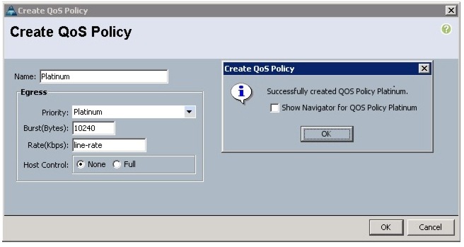
Creating a Platinum Policy
Follow these steps to create the Platinum QoS policy:
1.
2.
3.
4.
5.
6.
7.
8.
9.
10.
11.
Figure 21 Creating Platinum QoS Policy
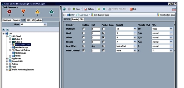
Setting Jumbo Frames
Follow these steps to set up Jumbo frames and enable the QoS:
1.
2.
3.
4.
5.
6.
7.
Figure 22 Setting Jumbo Frames
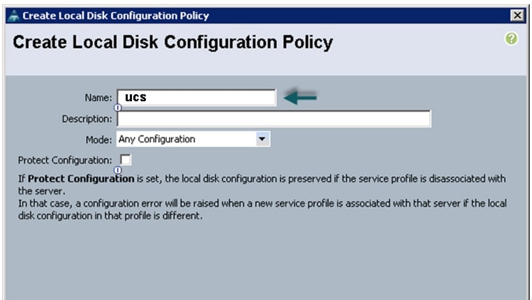
Creating a Local Disk Configuration Policy
Follow these steps to create a local disk configuration in the Cisco UCS Manager:
1.
2.
3.
4.
5.
6.
7.
8.
9.
Figure 23 Configuring Local Disk Policy
Creating a Server BIOS Policy
The BIOS policy feature in Cisco UCS automates the BIOS configuration process. The traditional mode of setting the BIOS is manual and is often error-prone. By creating a BIOS policy and assigning the policy to a server or group of servers, you can enable transparency within the BIOS settings configuration.
Note
Follow these steps to create a server BIOS policy using the Cisco UCS Manager:
1.
2.
3.
4.
5.
6.
Figure 24 Creating Server BIOS Policy
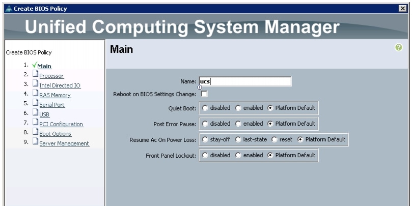
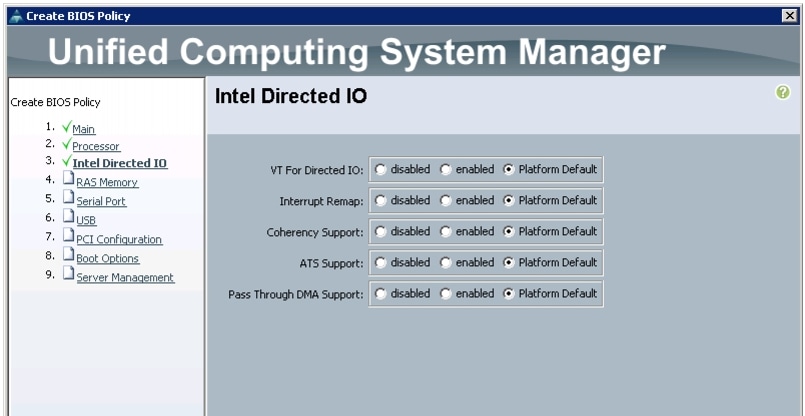
Figure 25 and Figure 26 show the Processor and Intel Directed IO properties settings in the BIOS Policy.
Figure 25 Creating Server BIOS Policy for Processor
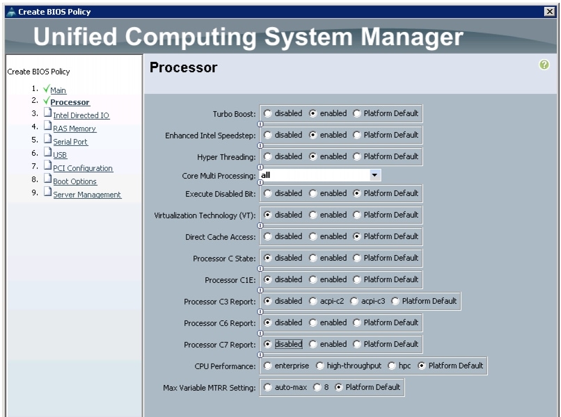
Figure 26 Creating Server BIOS Policy for Intel Directed IO
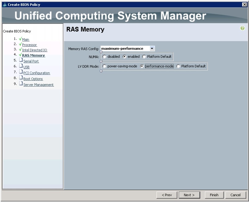
7.
Figure 27 Creating Server BIOS Policy for Memory
8.
9.
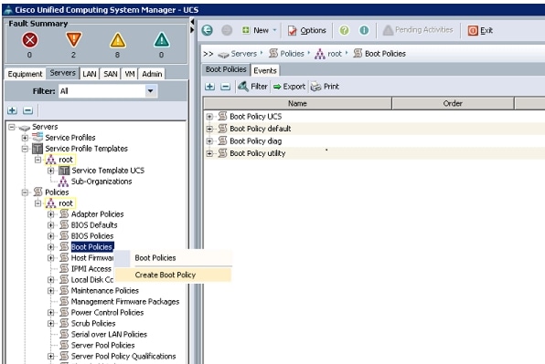
Creating a Boot Policy
Follow these steps to create a boot policy within Cisco UCS Manager:
1.
2.
3.
4.
Figure 28 Creating Boot Policy Part 1
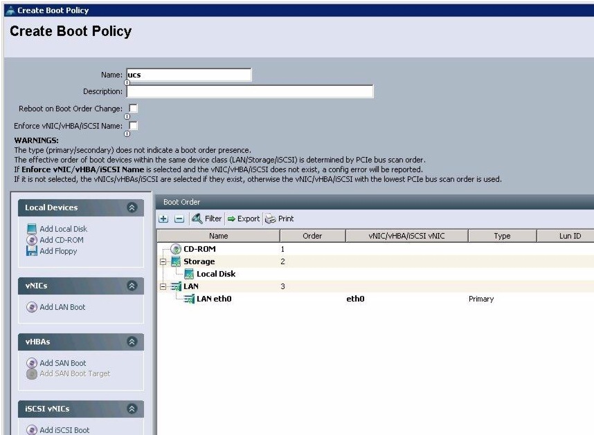
5.
6.
7.
8.
9.
10.
11.
12.
Figure 29 Creating Boot Policy Part 2
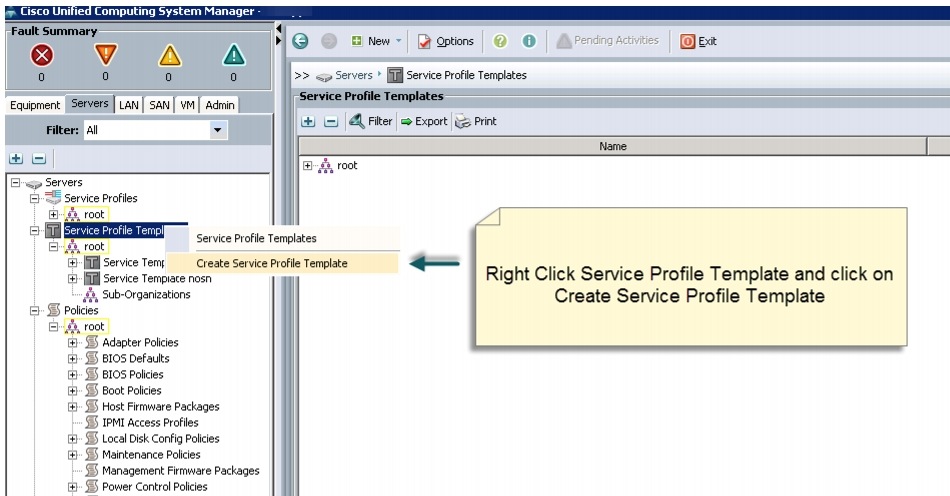
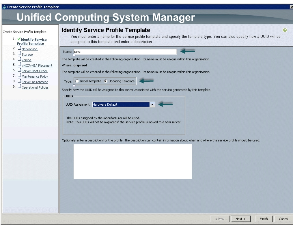
Creating a Service Profile Template
Follow these steps to create a service profile template in Cisco UCS Manager:
1.
2.
3.
4.
Figure 30 Creating Service Profile Template
5.
a.
b.
c.
6.
Figure 31 Identify Service Profile Template
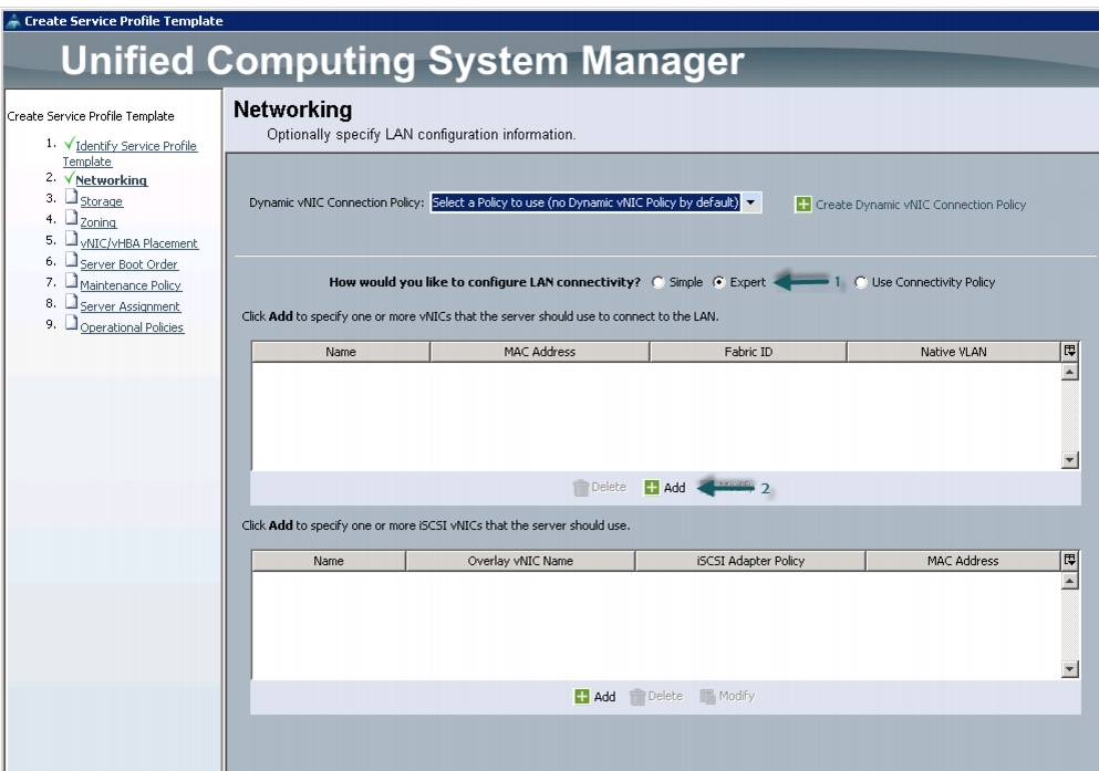
Configuring the Network Settings for the Template
In the Networking window, follow these steps to configure the network settings in the Cisco UCS Manager:
1.
2.
3.
Figure 32 Configuring Network Settings for the Template
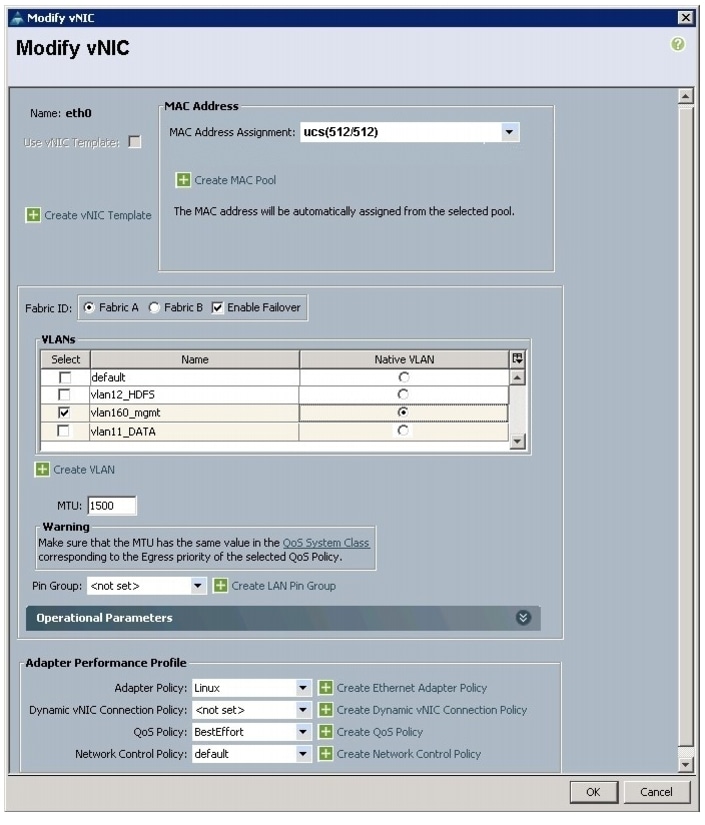
4.
5.
6.
7.
8.
9.
10.
11.
12.
13.
14.
Figure 33 Configuring vNIC eth0
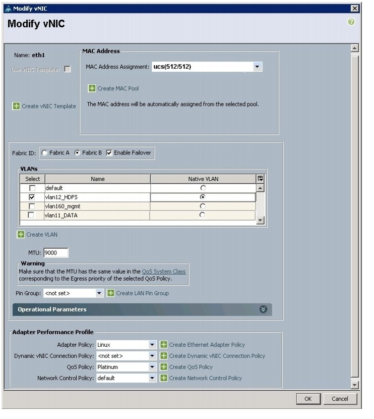
15.
16.
17.
18.
19.
20.
21.
22.
23.
24.
Figure 34 Configuring vNIC eth1
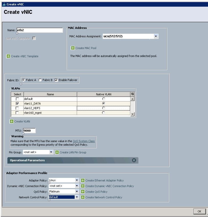
25.
26.
27.
28.
29.
30.
31.
32.
33.
34.
35.
Figure 35 Configuring vNIC eth2
Configuring a Storage Policy for the Template
In the Storage window, follow these steps to configure a storage policy in Cisco UCS Manager:
1.
2.
3.
Figure 36 Configuring Storage settings
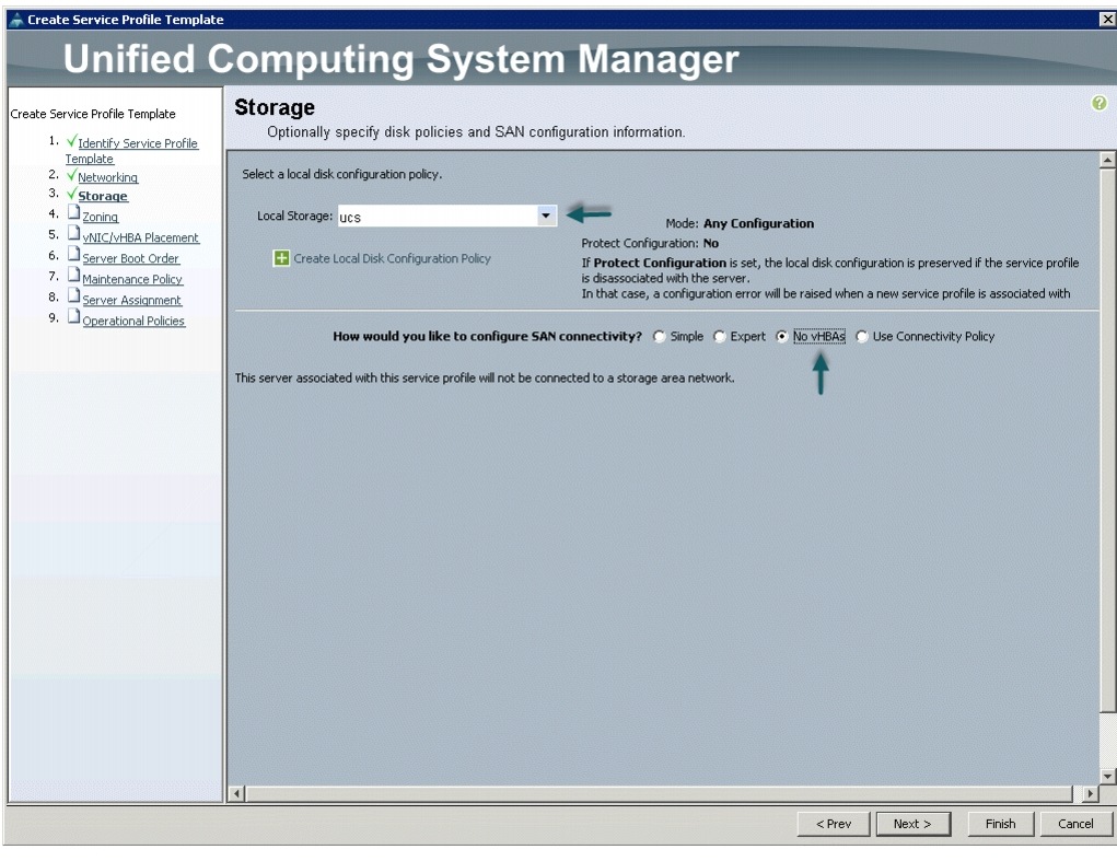
4.
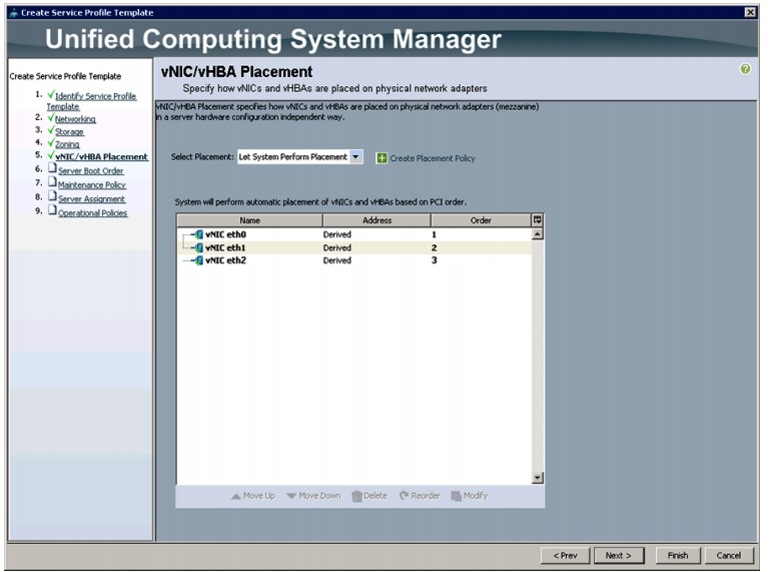
Configuring a vNIC/vHBA Placement for the Template
In the vNIC/vHBA window, follow these steps to configure a vNIC/vHBA placement policy in Cisco UCS Manager:
1.
2.
a.
b.
c.
Review to make sure that all vNICs are assigned in the appropriate order.
3.
Figure 37 vNIC/vHBA Placement
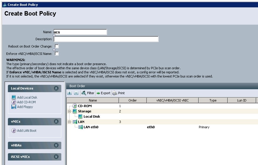
Configuring a Server Boot Order for the Template
In the Server Boot Order window, follow these steps to set the boot order for servers in Cisco UCS Manager:
1.
2.
Review to make sure that all the boot devices are created and identified.
3.
4.
Figure 38 Creating Boot Policy
5.
In the Maintenance Policy window, keep the default no policy as we have not created a policy. Click Next to continue to the next window.
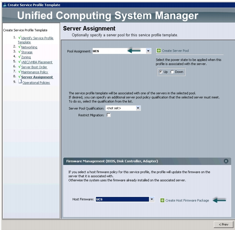
Configuring Server Assignment for the Template
In the Server Assignment window, follow these steps to assign the servers to the pool in Cisco UCS Manager:
1.
2.
3.
Figure 39 Server Assignment
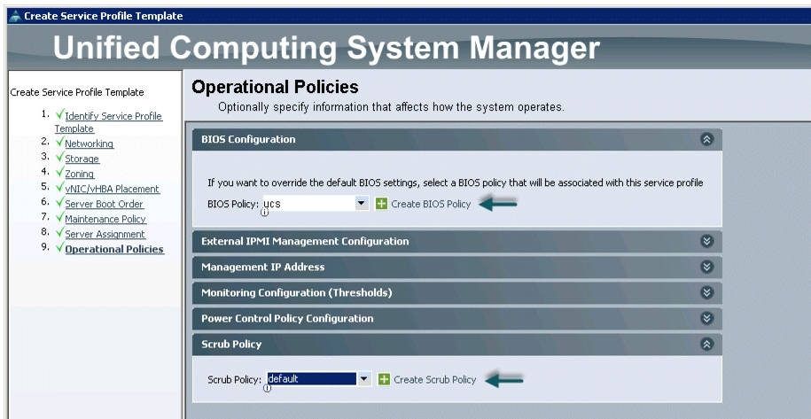
Configuring Operational Policies for the Template
In the Operational Policies window, follow these steps:
1.
2.
3.
Figure 40 Selecting BIOS Policy
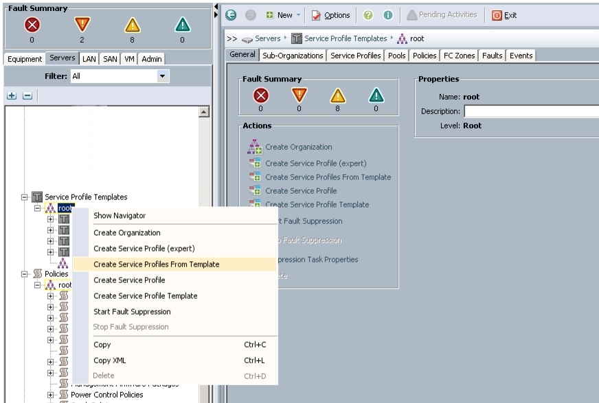
4.
a.
b.
Figure 41 Creating Service Profiles from Template
c.
Figure 42 Selecting Name and Total Number of Service Profiles
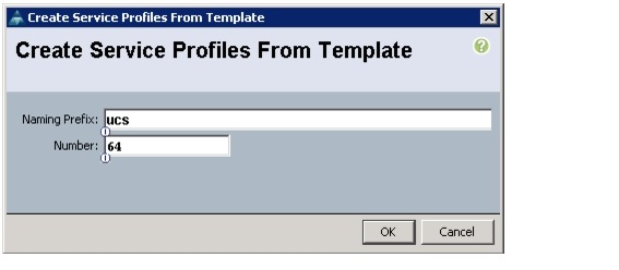
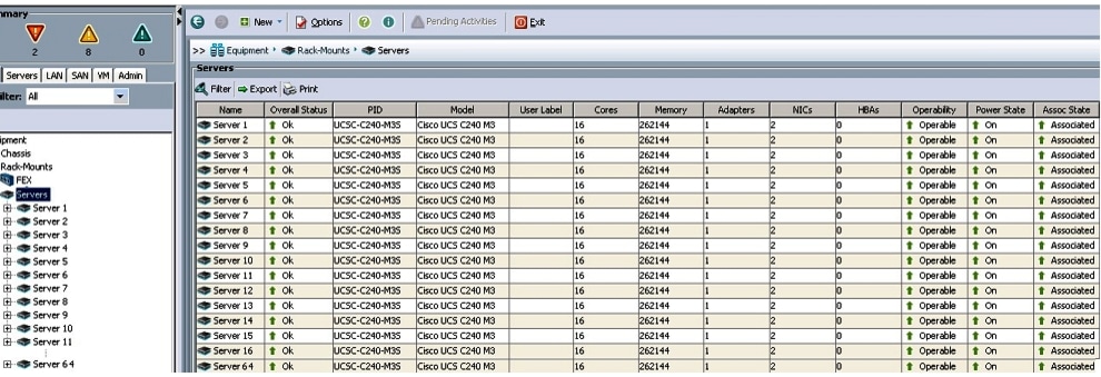
The Cisco UCS Manager discovers the servers and automatically associate these servers with service profiles. Figure 43 illustrates the service profiles associated with all the 64-nodes.
Figure 43 Cisco UCS Manager showing 64 Nodes
Configuring Disk Drives for Operating System on NameNode
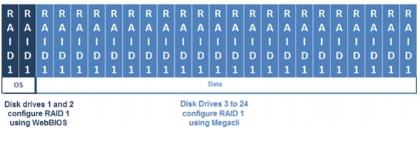
Namenode and Secondary Namenode have a different RAID configuration compared to Datanodes. This section details the configuration of disk drives for OS on these nodes (rhel1 and rhel2). The disk drives are configured as RAID1, read ahead cache and write cache are enabled when the battery is available. The first two disk drives are used for the Operating System and the remaining 22 disk drives are used for the HDFS as described in the following sections.
There are several ways to configure RAID such as using the LSI WebBIOS Configuration Utility embedded in the MegaRAID BIOS, booting DOS and running MegaCLI commands, using Linux-based MegaCLI commands, or using third party tools that have MegaCLI integrated. For this deployment, the first disk drive is configured using the LSI WebBIOS Configuration Utility and the remaining drives are configured using Linux-based MegaCLI commands after the completion of the Operating System installation.
Figure 44 RAID 1 Configured Using LSI WebBIOS Utility and MegaCLI
Follow these steps to create RAID1 on the first disk drive to install the Operating System:
1.
a.
b.
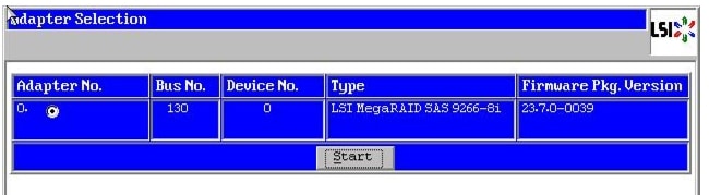
2.
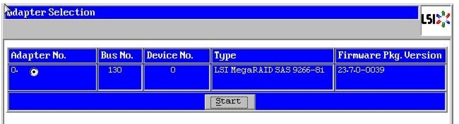
3.
Figure 45 Adapter Selection for RAID Configuration
4.
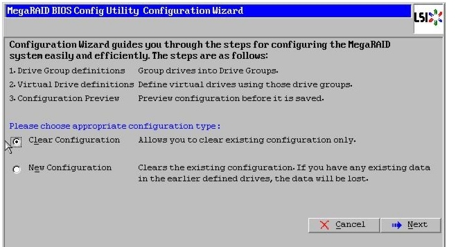
5.
Figure 46 Clearing Current configuration on the controller
6.
7.
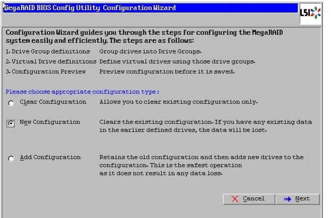
8.
9.
Figure 47 Choosing to create a New Configuration

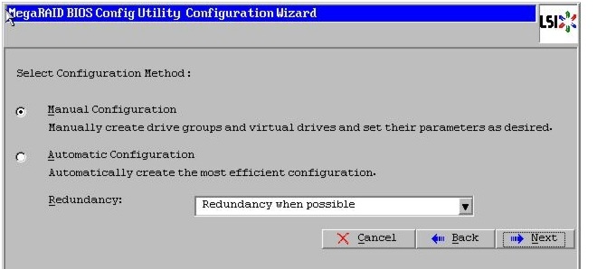
10.
Figure 48 Choosing Manual Configuration Method

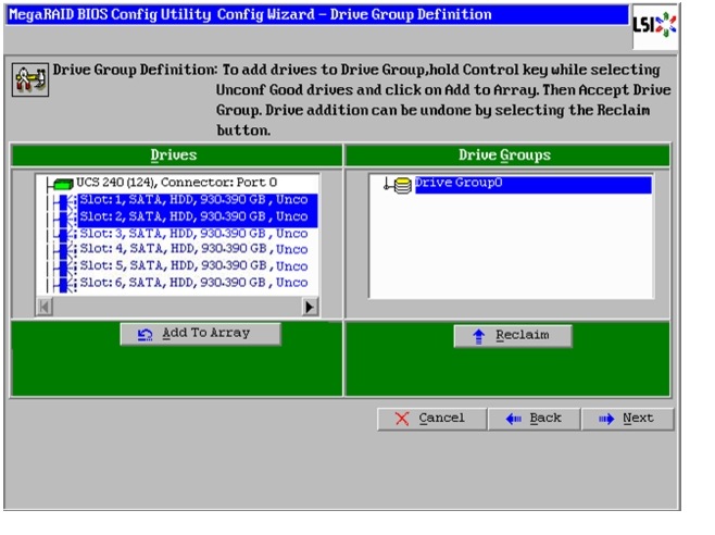
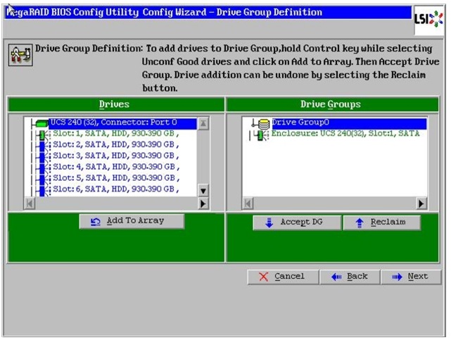
11.
12.
13.
14.
Figure 49 Selecting first drive and Adding to Drive Group
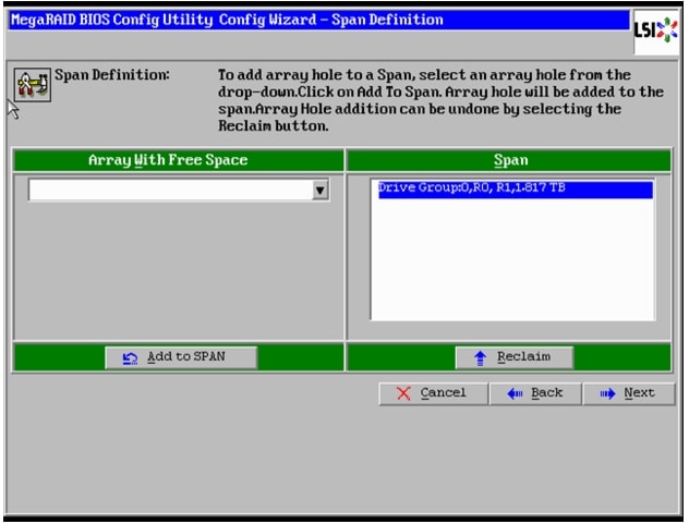
15.
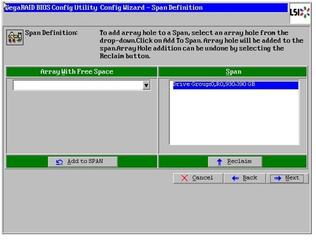
Figure 50 Span Definition Window
16.
a.
b.
c.
d.
e.
f.
g.
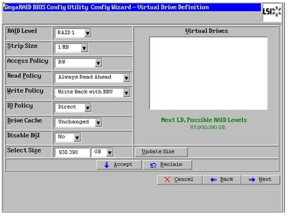
Note
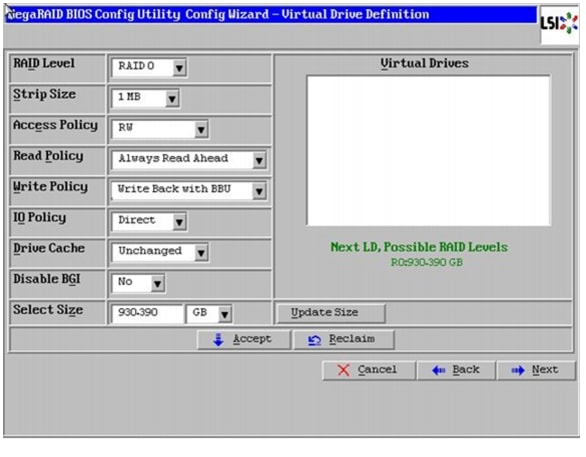
Figure 51 Defining Virtual Drive
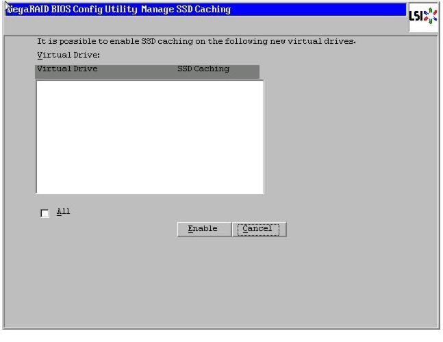
17.
18.
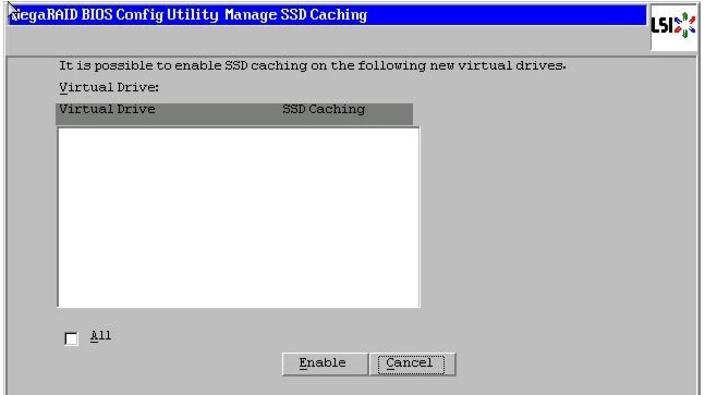
Figure 52 SSD Caching Window
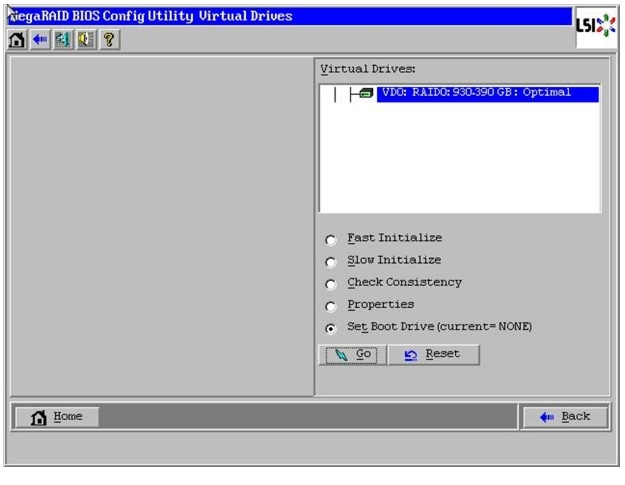
19.
20.
Figure 53 Setting Virtual Drive as Boot Drive
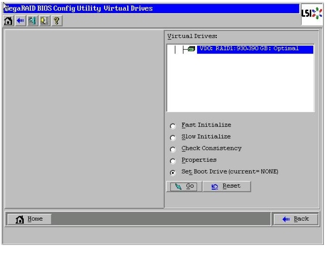
21.
22.
Configuration of disks 2 to 24 are done using Linux based MegaCLI commands described in "Configuring Data Drives on NameNode" section.
Configuring Disk Drives for Operating System on DataNodes
Nodes 3 through 64 are configured as DataNodes. This section details the configuration of disk drives for OS on the data nodes. The focus of this CVD is on the High Performance Configuration, featuring 24 1TB SFF disk drives. The disk drives are configured as individual RAID0 volumes with 1MB strip size. Read ahead cache and write cache are enabled when the battery is available. The first disk drive is used for the Operating System and the remaining 23 disk drives are used for the HDFS as described in the following sections.
Note
There are several ways to configure RAID. RAID can be configured using LSI WebBIOS Configuration Utility embedded in the MegaRAID BIOS, booting DOS and running MegaCLI commands, Linux based MegaCLI commands, or by third party tools having MegaCLI. For this deployment, the first disk drive is configured using LSI WebBIOS Configuration Utility and the rest of them are configured using a Linux based MegaCLI commands after the completion of OS installation.
Follow these steps to create RAID0 on the first disk drive to install the Operating System:
1.
a.
b.
2.
3.
Figure 54 Adapter Selection for RAID Configuration
4.
5.
Figure 55 Clearing Current configuration on the controller

6.
7.
8.
9.
Figure 56 Choosing to create a New Configuration
10.
Figure 57 Choosing Manual Configuration Method
11.
12.
13.
14.
Figure 58 Selecting first drive and Adding to Drive Group
15.
Figure 59 Span Definition Window
16.
a.
b.
c.
d.
e.
f.
g.
Note
Figure 60 Defining Virtual Drive
17.
18.
Figure 61 SSD Caching Window
19.
20.
Figure 62 Setting Virtual Drive as Boot Drive
21.
22.
Configuration of disks 3 to 24 are done using Linux based MegaCLI commands described in "Configuring Data Drives on DataNodes" section.
Installing Red Hat Linux 6.2 with KVM
The following section provides detailed procedures for installing Red Hat Linux 6.2.
There are multiple methods to install Red Hat Linux Operating System. The installation procedure described in this design guide uses KVM console and virtual media from Cisco UCS Manager.
1.
2.
3.
4.
Figure 63 Selecting KVM Console Option

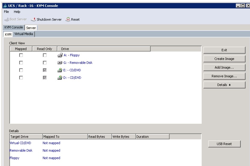
5.
6.
7.
Note
Figure 64 Adding an ISO Image
8.
9.
Figure 65 Mapping ISO Image
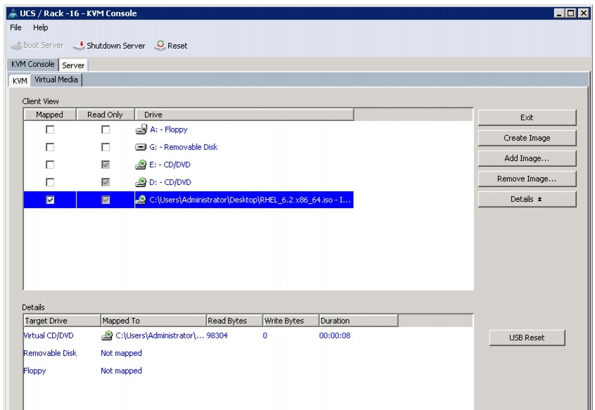
10.
11.
12.
13.
On reboot, the server detects the presence of the Red Hat Enterprise Linux Server 6.2 install media.
14.
Figure 66 Select Install Option

15.
16.
17.
18.
19.
20.
21.
22.
23.
24.
25.
26.
27.
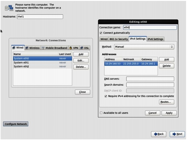
For this demonstration, the following values have been used:
IP Address: 10.29.160.53
Netmask: 255.255.255.0
Gateway: 10.29.160.1
28.
29.
Figure 67 Configuring Network for eth0
30.
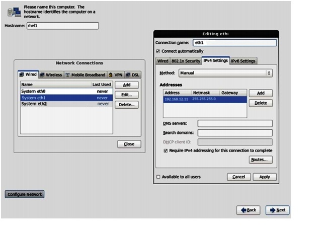
IP Address: 192.168.12.11
Netmask: 255.255.255.0
Figure 68 Configuring Network for eth1
31.
IP Address: 192.168.11.11
Netmask: 255.255.255.0
32.
33.
34.
35.
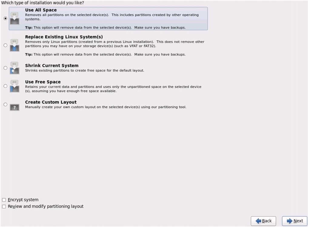
Figure 69 Selecting Install Option
36.
37.
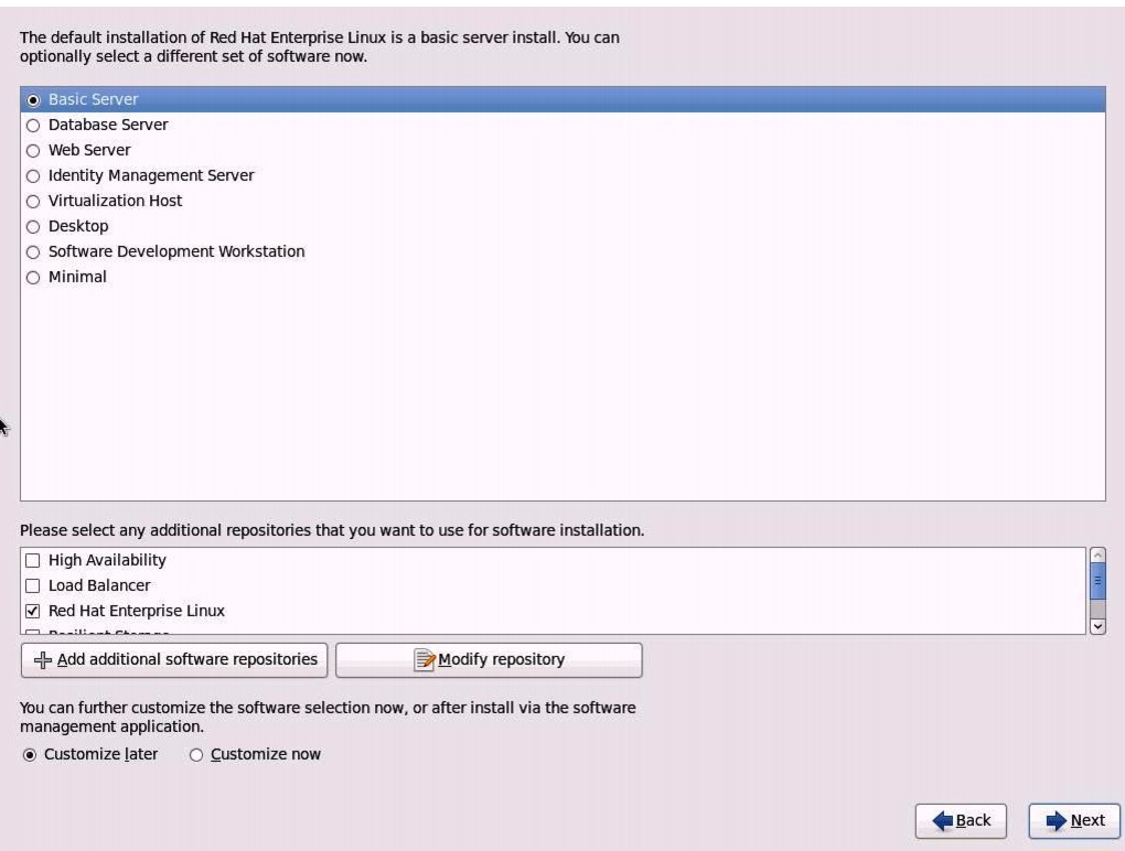
Figure 70 Selecting Type of Installation
38.
39.
Repeat the above steps (1 to 39) to install the Red Hat Linux on servers 2 through 64.
Note
Table 5 describes the hostnames and their corresponding IP addresses.
Post OS Install Configuration
Choose one of the nodes of the cluster or a separate node as an Admin Node for management such as HDP installation, parallel shell, creating a local Red Hat repo and others. In this document, we have used rhel1 for management.
Setting Up Password-less Login
To manage all of the cluster nodes from the admin node we need to setup password-less login. It assists in automating common tasks with Parallel-SSH (pssh) and shell-scripts without having passwords.
Once Red Hat Linux is installed across all the nodes in the cluster, follow these steps in order to enable password less login across all the nodes.
1.
ssh 10.29.160.532.
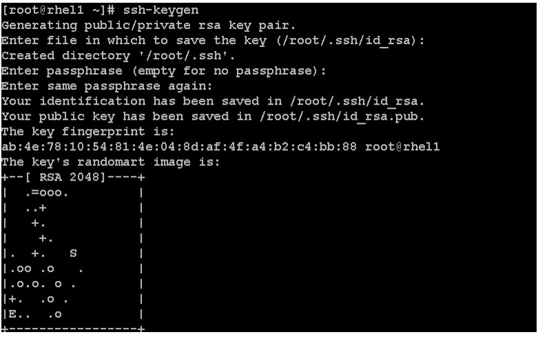
3.
for IP in {53..116}; do echo -n "$IP -> "; ssh-copy-id -i ~/.ssh/id_rsa.pub
10.29.160.$IP; done
4.
5.
Installing and Configuring Parallel SSH
Installing Parallel-SSH
Parallel-ssh is used to run commands on several hosts at the same time. It takes a file of hostnames and a few common ssh parameters as parameters, and executes the given command in parallel on the specified nodes.
1.
wget https://parallel-ssh.googlecode.com/files/pssh-2.3.1.tar.gzscp pssh-2.3.1.tar.gz rhel1:/root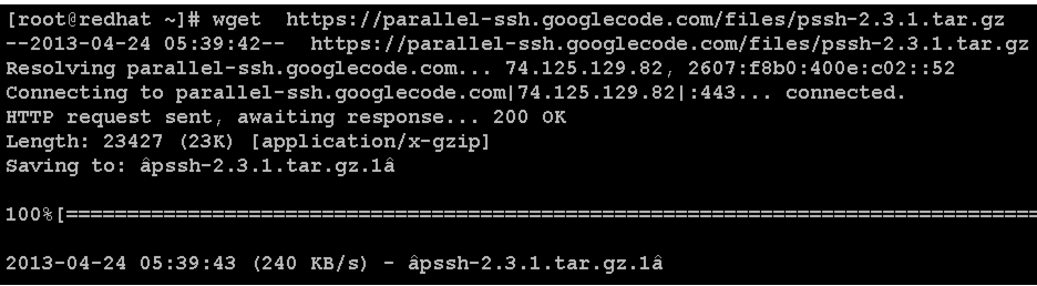
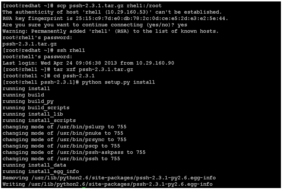
2.
ssh rhel1tar xzf pssh-2.3.1.tar.gzcd pssh-2.3.1python setup.py install
3.
4.
vi /root/allnodes# This file contains ip address of all nodes of the cluster#used by parallel-shell (pssh). For Details man pssh10.29.160.5310.29.160.5410.29.160.5510.29.160.5610.29.160.5710.29.160.5810.29.160.5910.29.160.6010.29.160.6110.29.160.6210.29.160.6310.29.160.6410.29.160.6510.29.160.6610.29.160.6710.29.160.68...10.29.160.116vi /root/datanodes10.29.160.5510.29.160.5610.29.160.5710.29.160.5810.29.160.5910.29.160.6010.29.160.6110.29.160.6210.29.160.6310.29.160.6410.29.160.6510.29.160.6610.29.160.6710.29.160.68...10.29.160.116Installing Cluster Shell
1.
Cluster shell is available from the Extra Packages for Enterprise Linux (EPEL) repository.
wget
http://dl.fedoraproject.org/pub/epel//6/x86_64/clustershell-1.6-1.el6.noarch.rpm
scp clustershell-1.6-1.el6.noarch.rpm rhel1:/root/2.
yum install clustershell-1.6-1.el6.noarch.rpm3.
For 64 node cluster all: rhel[1-64]
Note
Configuring /etc/hosts
Follow these steps to create the host file across all the nodes in the cluster:
1.
vi /etc/hosts127.0.0.1 localhost localhost.localdomain localhost4 localhost4.localdomain4::1 localhost localhost.localdomain localhost6 localhost6.localdomain6192.168.12.11 rhel1192.168.12.12 rhel2192.168.12.13 rhel3192.168.12.14 rhel4192.168.12.15 rhel5192.168.12.16 rhel6192.168.12.17 rhel7192.168.12.18 rhel8192.168.12.19 rhel9192.168.12.20 rhel10192.168.12.21 rhel11192.168.12.22 rhel12192.168.12.23 rhel13192.168.12.24 rhel14192.168.12.25 rhel15192.168.12.26 rhel16...192.168.12.74 rhel642.
pscp -h /root/allnodes /etc/hosts /etc/hosts

Creating Red Hat Local Repository
To create a repository using RHEL DVD or ISO on the admin node (in this deployment rhel1 is used for this purpose), create a directory with all the required rpms, run the createrepo command and then publish the resulting repository.
1.
mkdir -p /var/www/html/rhelrepo2.
3.
scp rhel-server-6.2-x86_64-dvd.iso rhel1:/rootAssuming the Red Hat ISO file is located in your working directory.
mkdir -p /mnt/rhelisomount -t iso9660 -o loop /root/rhel-server-6.2-x86_64-dvd.iso /mnt/rheliso/4.
cp -r /mnt/rheliso/* /var/www/html/rhelrepo5.
vi /var/www/html/rhelrepo/rheliso.repo[rhel6.2]name=Red Hat Enterprise Linux 6.2baseurl=http://10.29.160.53/rhelrepogpgcheck=0enabled=1
Note
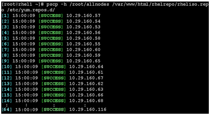
6.
pscp -h /root/allnodes /var/www/html/rhelrepo/rheliso.repo /etc/yum.repos.d/
7.
vi /etc/yum.repos.d/rheliso.repo[rhel6.2]name=Red Hat Enterprise Linux 6.2baseurl=file:///var/www/html/rhelrepogpgcheck=0enabled=18.
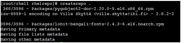
Creating the Red Hat Repository Database
1.
2.
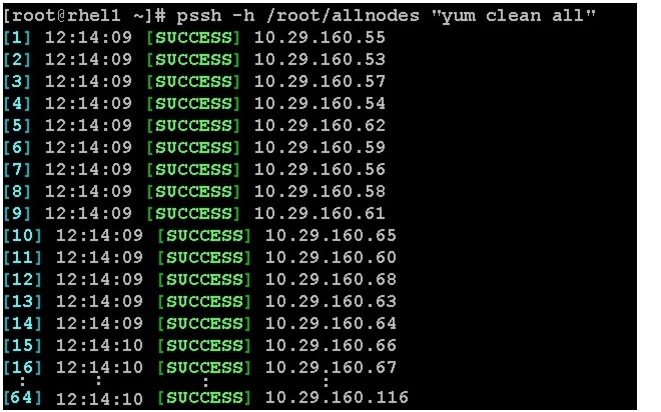
3.
yum -y install createrepocd /var/www/html/rhelrepocreaterepo .yum clean all
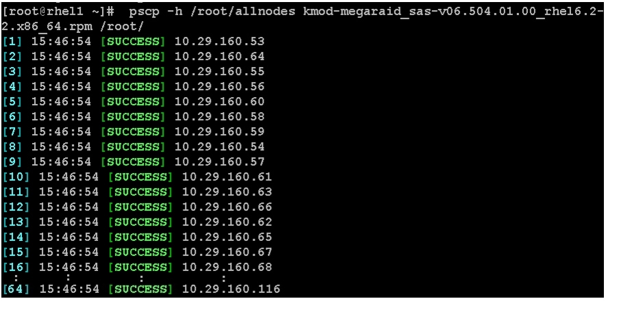
Upgrading LSI driver
The latest LSI driver is essential for performance and bug fixes.
To download the latest LSI drivers, see:
1.

2.
3.
pscp -h /root/allnodes kmod-megaraid_sas-v06.504.01.00_rhel6.2-2.x86_64.rpm /root/
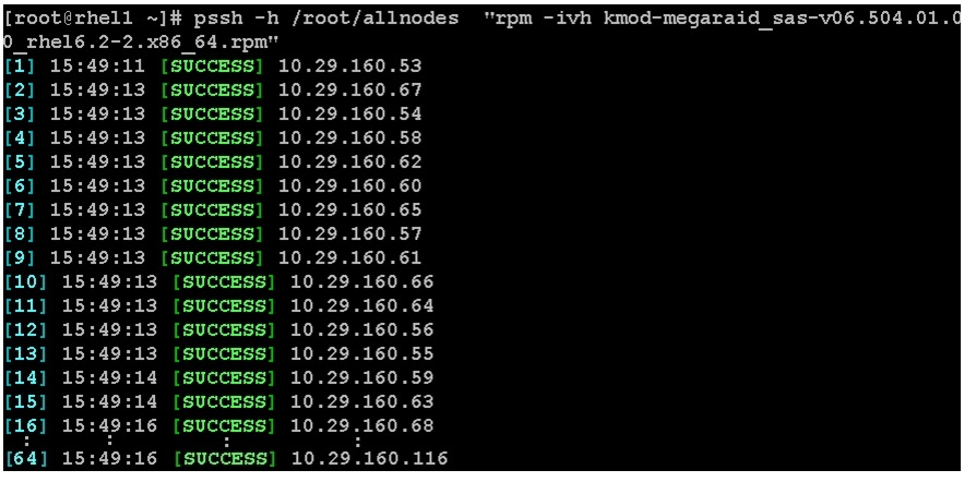
pssh -h /root/allnodes  "rpm -ivh
kmod-megaraid_sas-v06.504.01.00_rhel6.2-2.x86_64.rpm"
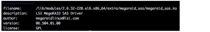
4.
pssh -h /root/allnodes "modinfo megaraid_sas | head -5"
Installing httpd
1.
The Red Hat repository is hosted using http on the admin node, and this machine is accessible by all the hosts in the cluster.
yum -y install httpd2.
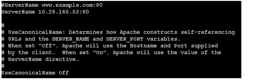
/etc/httpd/conf/httpd.conf
3.
chcon -R -t httpd_sys_content_t /var/www/html/rhelrepo4.
service httpd startchkconfig httpd onJDK Installation
Download Java SE 6 Development Kit (JDK)
Using a web browser, click on the following link:
http://www.oracle.com/technetwork/java/index.html
and download the latest Java™ SE 6 Development Kit (JDK™6).
Once the JDK6 package has been downloaded, place it in the /var/www/html/JDK/ directory.
Install JDK6 on All Node
Create the following script install_jdk.sh to install JDK:
Script install_jdk.sh
# Copy and install JDKcd /tmp/curl http://10.29.160.53/JDK/jdk-6u41-linux-x64.bin -O -Lsh ./jdk-6u41-linux-x64.bin -noregisterCopy script disable_services.sh to all nodes and run the script on all nodes:
pscp -h /root/pssh.hosts /root/install_jdk.sh /root/pssh -h /root/pssh.hosts "/root/install_jdk.sh"Extjs Installation
From a host connected to the Internet, download the Extjs and transfer it to rhel1.
wget
http://s3.amazonaws.com/public-repo-1.hortonworks.com/HDP-UTILS-1.1.0.15/repos/centos6
/extjs/extjs-2.2-1.noarch.rpm
Copy the extjs rpm to all nodes from the admin node.
pscp -h /root/allnodes /root/extjs-2.2-1.noarch.rpm /root/Install extjs on all nodes.
pssh -h /root/allnodes "yum -y install /root/extjs-2.2-1.noarch.rpm"NTP Configuration
The Network Time Protocol (NTP) is used to synchronize the time of all the nodes within the cluster. The Network Time Protocol daemon (ntpd) sets and maintains the system time of day in sync with the timeserver located in the admin node (rhel1). Configuring NTP is critical for any Hadoop Cluster. If server clocks in the cluster drift out of sync, serious problems can occur in the HBase and other services.
Note
1.
vi /etc/ntp.confdriftfile /var/lib/ntp/driftrestrict 127.0.0.1restrict -6 ::1server 127.127.1.0fudge 127.127.1.0 stratum 10includefile /etc/ntp/crypto/pwkeys /etc/ntp/keys2.
vi /root/ntp.confserver 10.29.160.53driftfile /var/lib/ntp/driftrestrict 127.0.0.1restrict -6 ::1includefile /etc/ntp/crypto/pwkeys /etc/ntp/keys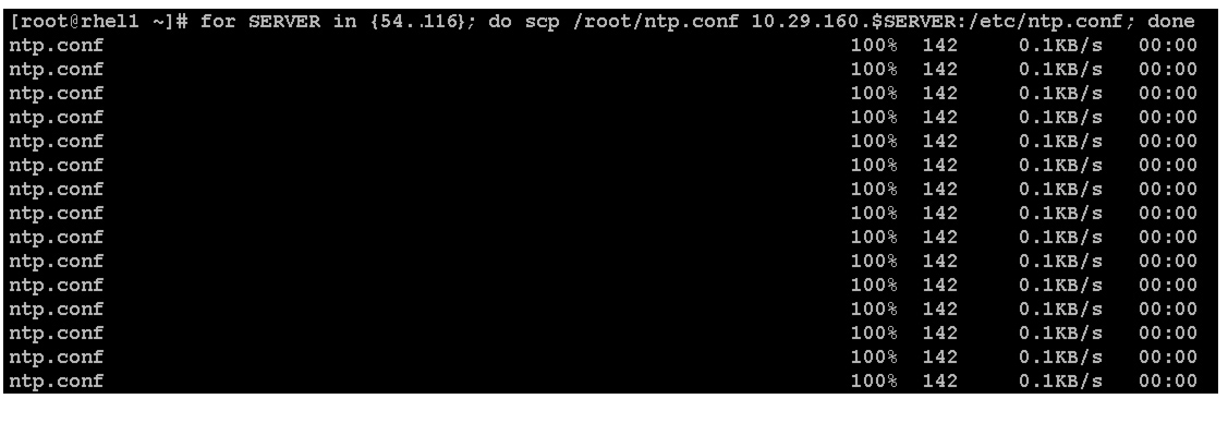
3.
for SERVER in {54..116};do scp /root/ntp.conf10.29.160.$SERVER:/etc/ntp.conf; done
Note
4.
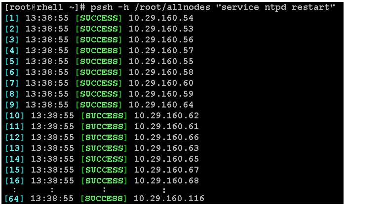
pssh -h /root/allnodes "yum install -y ntpdate"pssh -h /root/allnodes "service ntpd stop"pssh -h /root/allnodes "ntpdate rhel1"pssh -h /root/allnodes "service ntpd start"
5.
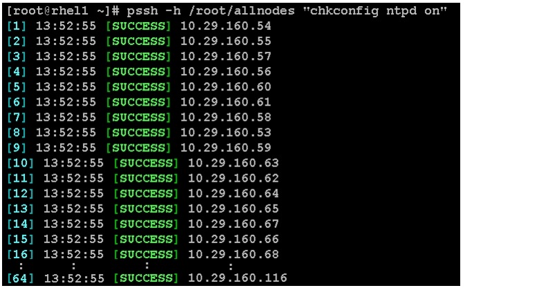
pssh -h /root/allnodes "chkconfig ntpd on"
Enabling Syslog
Syslog must be enabled on each node to preserve logs regarding killed processes or failed jobs. Modern versions such as syslog-ng and rsyslog are possible, making it more difficult to ascertain if a syslog daemon is present.
Run any of the commands to confirm if the service is properly configured:
clush -B -a rsyslogd -vclush -B -a service rsyslog statusSetting Ulimit
On each node, ulimit -n specifies the number of inodes that can be opened simultaneously. With the default value of 1024, the system appears to be out of disk space and shows no inodes available. This value should be set to 64000 on every node.
Higher values are unlikely to result in an appreciable performance gain.
1.
root soft nofile 64000root hard nofile 640002.
clush -B -a ulimit -nThe command should report 64000 as the ulimit.
Note
Disabling SELinux
SELinux must be disabled during the HDP installation procedure and cluster setup. SELinux can be enabled after installation and while the cluster is running.
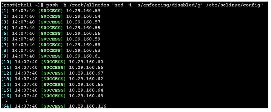
SELinux can be disabled by editing /etc/selinux/config and changing the SELINUX line to SELINUX=disabled.
1.
pssh -h /root/allnodes "sed -i 's/SELINUX=enforcing/SELINUX=disabled/g'
/etc/selinux/config "
pssh -h /root/allnodes "setenforce 0"
Note
Setting TCP Retries Parameter
Adjusting the tcp_retries parameter for the system network enables faster detection of failed nodes. Given the advanced networking features of UCS, this is a safe and recommended change (failures observed at the Operating System layer are mostly serious rather than transitory). On each node, set the number of TCP retries to 5 can help detect unreachable nodes with less latency.
1.
net.ipv4.tcp_retries2=52.
clush -B -a sysctl -pDisabling the Linux Firewall
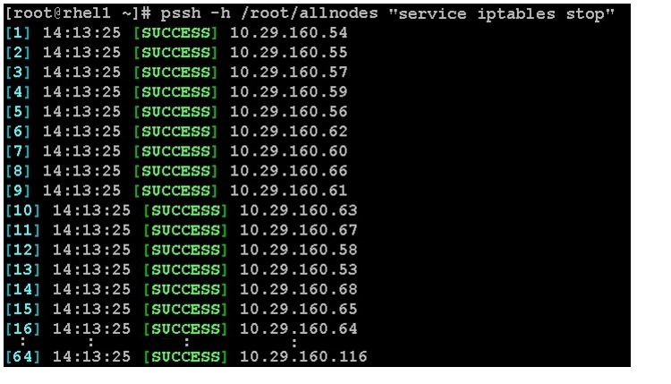
The default Linux firewall settings are far too restrictive for any Hadoop deployment. Since the Cisco UCS Big Data deployment is performed in the isolated network, there is no need to leave the iptables service running.
1.
pssh -h /root/allnodes "service iptables stop"
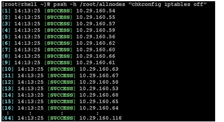
2.
pssh -h /root/allnodes "chkconfig iptables off"
Configuring Data Drives on NameNode
This section provides the steps to configure data drives on the NameNode.
The first two disk drives are configured for the Operating System on the nodes, rhel1 and rhel2, as shown in "Configuring Disk Drives for Operating System on NameNode" section. The remaining disk drives can be configured similarly or by using MegaCli.
1.
scp /root/MegaCli64 rhel1:/root/scp /root/Lib_Utils-1.00-08.noarch.rpm rhel1:/root/scp /root/Lib_Utils2-1.00-01.noarch.rpm rhel1:/root/2.
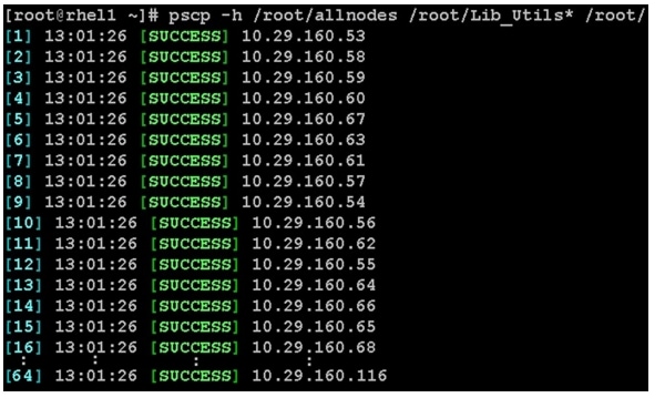
pscp -h /root/allnodes /root/MegaCli64 /root/
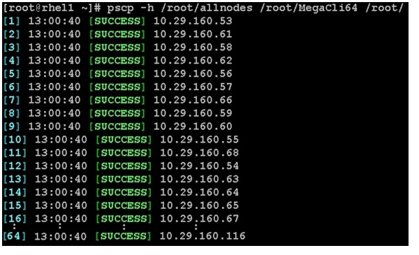
pscp -h /root/allnodes /root/Lib_Utils* /root/
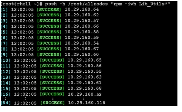
3.
pssh -h /root/allnodes "rpm -ivh Lib_Utils*"
4.
vi /root/raid1.sh./MegaCli64 -cfgldadd r1[$1:3,$1:4,$1:5,$1:6,$1:7,$1:8,$1:9,$1:10,$1:11,$1:12,$1:13,$1:14,$1:15,$1:16,$1 :17,$1:18,$1:19,$1:20,$1:21,$1:22,$1:23,$1:24] wb ra nocachedbadbbu strpsz1024 -a0The above script requires enclosure ID as a parameter. Run the following command to get enclousure id../MegaCli64 pdlist -a0 | grep Enc | grep -v 252 | awk '{print $4}' | sort | uniq -c | awk '{print $2}'chmod 755 raid1.shRun MegaCli script as follows./raid1.sh <EnclosureID obtained by running the command above>WB: Write backRA: Read AheadNoCachedBadBBU: Do not write cache when the BBU is bad.Strpsz1024: Strip Size of 1024K
Note
Configuring the Filesystem for NameNodes
To Configure the filesystem for NameNodes, run the following script:
vi /root/driveconf.sh#!/bin/bashdisks_count=`lsblk -id | grep sd | wc -l`if [ $disks_count -eq 2 ]; thenecho "Found 2 disks"elseecho "Found $disks_count disks. Expecting 2. Exiting.."exit 1fi[[ "-x" == "${1}" ]] && set -x && set -v && shift 1for X in /sys/class/scsi_host/host?/scandoecho '- - -' > ${X}donefor X in /dev/sd?doecho $Xif [[ -b ${X} && `/sbin/parted -s ${X} print quit|/bin/grep -c boot` -ne 0 ]]thenecho "$X bootable - skipping."continueelseY=${X##*/}1/sbin/parted -s ${X} mklabel gpt quit/sbin/parted -s ${X} mkpart 1 6144s 100% quit/sbin/mkfs.xfs -f -q -l size=65536b,lazy-count=1,su=256k -d sunit=1024,swidth=6144 -r extsize=256k -L ${Y} ${X}1(( $? )) && continue/bin/mkdir -p /HDP/${Y}(( $? )) && continue/bin/mount -t xfs -o allocsize=128m,noatime,nobarrier,nodiratime ${X}1 /HDP/${Y}(( $? )) && continueecho "LABEL=${Y} /HDP/${Y} xfs allocsize=128m,noatime,nobarrier,nodiratime 0 0" >> /etc/fstabfidoneConfiguring Data Drives on DataNodes
This section provides the steps to configure data drives on DataNodes.
The first disk drive is configured for the Operating System on all the DataNodes, rhel3 to rhel64 as shown in "Configuring Disk Drives for Operating System on DataNodes" section. The remaining disk drives can be configured similarly or by using MegaCli.
Run the following command from the admin node to create the virtual drives with RAID 0 configurations on all the DataNodes.
pssh -h /root/datanodes "./MegaCli64 -cfgeachdskraid0 WB RA direct NoCachedBadBBU
strpsz1024 -a0"
WB: Write back
RA: Read Ahead
NoCachedBadBBU: Do not write cache when the BBU is bad
Strpsz1024: Strip Size of 1024K
Note
Configuring the Filesystem for DataNodes
This section describes the procedure to configure the filesystem for DataNodes.
1.
To create partition tables and file systems on the local disks of each nodes, run the following script as the root user on all the nodes.
vi /root/driveconf.sh#!/bin/bashdisks_count=`lsblk -id | grep sd | wc -l`if [ $disks_count -eq 24 ]; thenecho "Found 24 disks"elseecho "Found $disks_count disks. Expecting 24. Exiting.."exit 1fi[[ "-x" == "${1}" ]] && set -x && set -v && shift 1for X in /sys/class/scsi_host/host?/scandoecho '- - -' > ${X}donefor X in /dev/sd?doecho $Xif [[ -b ${X} && `/sbin/parted -s ${X} print quit|/bin/grep -c boot` -ne 0 ]]thenecho "$X bootable - skipping."continueelseY=${X##*/}1/sbin/parted -s ${X} mklabel gpt quit/sbin/parted -s ${X} mkpart 1 6144s 100% quit/sbin/mkfs.xfs -f -q -l size=65536b,lazy-count=1,su=256k -d sunit=1024,swidth=6144 -r extsize=256k -L ${Y} ${X}1(( $? )) && continue/bin/mkdir -p /HDP/${Y}(( $? )) && continue/bin/mount -t xfs -o allocsize=128m,noatime,nobarrier,nodiratime ${X}1 /HDP/${Y}(( $? )) && continueecho "LABEL=${Y} /HDP/${Y} xfs allocsize=128m,noatime,nobarrier,nodiratime 0 0" >> /etc/fstabfidone2.
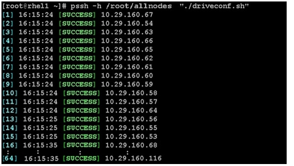
pscp -h /root/datanodes /root/driveconf.sh /root/3.
pssh -h /root/datanodes "./driveconf.sh"
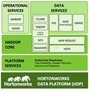
Installing HDP
HDP is an enterprise grade, hardened Hadoop distribution. HDP combines Apache Hadoop and its related projects into a single tested and certified package. It offers the latest innovations from the open source community with the testing and quality you expect from the enterprise quality software. HPD components are depicted in Figure 71.
Figure 71 HDP Components
Prerequisites for HDP Installation
This section details the prerequisites for HDP installation such as setting up of EPEL and HDP Repo.
Hortonworks and EPEL Repo
From a host connected to the Internet, download the EPEL and Hortonworks repositories as shown below and transfer it to rhel1.
1.
mkdir -p /tmp/Hortonworkscd /tmp/Hortonworksrpm -Uvh http://download.fedoraproject.org/pub/epel/6/x86_64/epel-release-6-8.noarch.rpmreposync -r epel2.
wget
http://public-repo-1.hortonworks.com/HDP/centos6/HDP-1.3.0.0-centos6-rpm.tar.gz
3.
wget
http://public-repo-1.hortonworks.com/HDP-UTILS-1.1.0.15/repos/centos6/HDP-UTILS-1.
1.0.15-centos6.tar.gz
4.
wget
http://public-repo-1.hortonworks.com/ambari/centos6/ambari-1.2.3.7-centos6.tar.gz
5.
scp -r /tmp/Hortonworks/ rhel1:/var/www/html6.
login to rhel1cd /var/www/html/Hortonworkstar -zxvf HDP-1.3.0.0-centos6-rpm.tar.gztar -zxvf HDP-UTILS-1.1.0.15-centos6.tar.gztar -zxvf ambari-1.2.3.7-centos6.tar.gz7.
vi /etc/yum.repos.d/hdp.repo[HDP-1.3.0.0.]name=Hortonworks Data Platform Version - HDP-1.3.0.0baseurl=http://10.29.160.53/Hortonworks/HDP/centos6/1.x/GA/1.3.0.0/gpgcheck=0enabled=1priority=18.
vi /etc/yum.repos.d/hdp-utils.repo[HDP-UTILS-1.1.0.15]name=Hortonworks Data Platform Version -HDP-UTILS-1.1.0.15baseurl=http://10.29.160.53/Hortonworks/HDP-UTILS-1.1.0.15/repos/centos6gpgcheck=0enabled=1priority=19.
vi /etc/yum.repos.d/ambari.repo[Updates-ambari-1.2.3.7]name=ambari-1.2.3.7 - Updatesbaseurl=http://rhel1/Hortonworks/ambari/centos6/1.x/updates/1.2.3.7gpgcheck=0enabled=1priority=110.
cd /var/www/html/Hortonworks/epelcreaterepo .vi /etc/yum.repos.d/epel.reponame=Extra Packages for Enterprise Linux 6 - $basearchbaseurl=http://rhel1/Hortonworks/epel/enabled=1gpgcheck=0priority=1From the admin node copy the repo files to /etc/yum.repos.d/ of all the nodes of the cluster.
pscp -h /root/allnodes /etc/yum.repos.d/hdp* /etc/yum.repos.d/pscp -h /root/allnodes /etc/yum.repos.d/ambari.repo /etc/yum.repos.d/pscp -h /root/allnodes /etc/yum.repos.d/epel.repo /etc/yum.repos.d/HDP Installation
To install HDP, issue the following CLI commands:
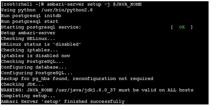
Install and Setup Ambari Server on rhel1
yum install ambari-serverSetup Ambari Server
ambari-server setup -j $JAVA_HOME
Configure Ambari Server to use Local Repository
Edit redhat6 and centos6 sections of the Ambari repoinfo.xml to point to local repository.
vi /var/lib/ambari-server/resources/stacks/HDPLocal/1.3.0/repos/repoinfo.xmlReplace the xml element <os type="redhat6"> .. </os> with<os type="redhat6"><repo><baseurl>http://10.29.160.53/Hortonworks/HDP/centos6/1.x/GA/1.3.0.0</baseurl><repoid>HDP-1.3.0</repoid><reponame>HDP</reponame></repo><repo><baseurl>http://10.29.160.53/Hortonworks/epel</baseurl><repoid>HDP-epel</repoid><reponame>HDP-epel</reponame><mirrorslist><![CDATA[http://mirrors.fedoraproject.org/mirrorlist?repo=epel-6&arch=$basear ch]]></mirrorslist></repo></os>Replace the xml element <os type="centos6"> .. </os> with<os type="centos6"><repo><baseurl>http://10.29.160.53/Hortonworks/HDP/centos6/1.x/GA/1.3.0.0</baseurl><repoid>HDP-1.3.0</repoid><reponame>HDP</reponame></repo><repo><baseurl>http://10.29.160.53/Hortonworks/epel</baseurl><repoid>HDP-epel</repoid><reponame>HDP-epel</reponame><mirrorslist><![CDATA[http://mirrors.fedoraproject.org/mirrorlist?repo=epel-6&arch=$basear ch]]></mirrorslist></repo></os>Start Ambari Server
ambari-server startConfirm Ambari Server Startup
ps -ef | grep ambari-serverLogin to Ambari Server
Once the Ambari service has been started, access the Ambari Install Wizard through the browser.
1.
2.
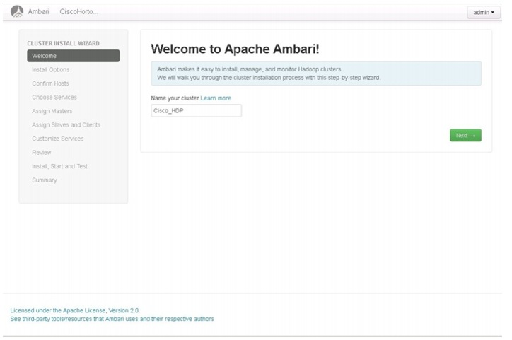
Create Cluster Name
Follow these steps to create the cluster name:
1.
Figure 72 Apache Ambari - Home Page
HDP Cluster Installation
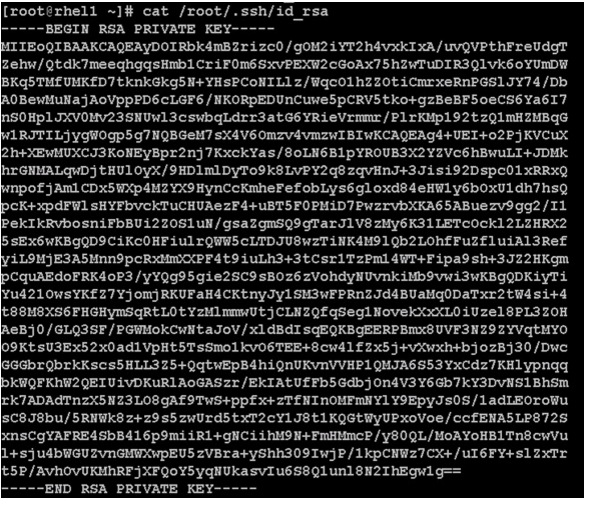
In order to build a cluster, the install wizard needs to have a general information about how the cluster needs to be set up. For this, you need to provide the Fully Qualified Domain Name (FQDN) of each one of the hosts. The wizard also needs to access the private key file that was created in "Setting Up Password-less Login" section. It uses these to locate all the hosts in the system and to access and interact with them securely.
1.
2.
a.
Note
Figure 73 Copying Contents from /root/.ssh/id_rsa
3.
4.
5.
Figure 74 Confirming the HDP Installation
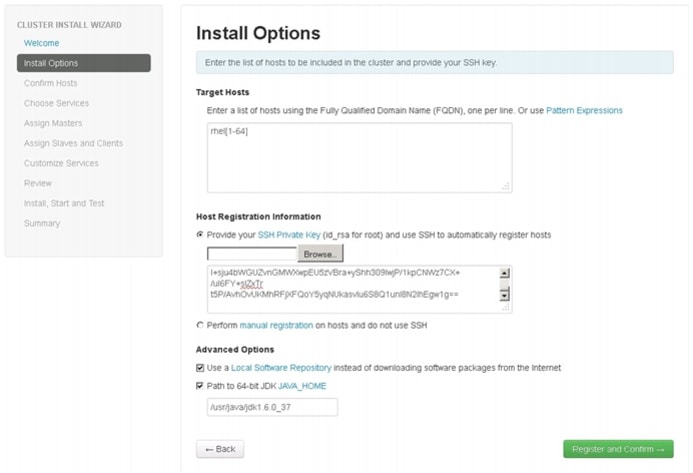
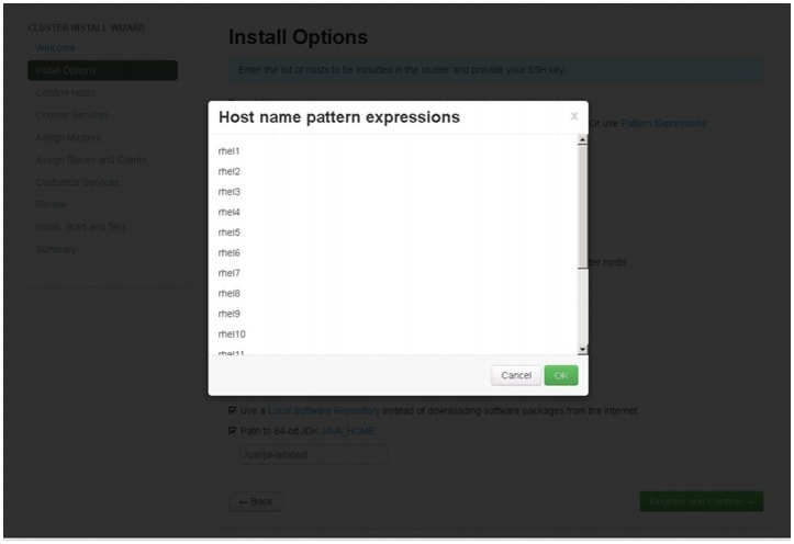
Host Name Pattern Expressions
Figure 75 shows a list of target host names using pattern expressions.
Figure 75 Host Name Pattern Expressions
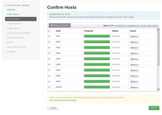
Confirming Hosts
This screen allows you to make sure that the Ambari server has located all the required hosts for the cluster and to make sure that the hosts have correct directories, packages, and processes to continue the installation process.
You can remove the undesired hosts that were selected by the Ambari server. To remove all the undesired hosts, check the appropriate check boxes provided against each of the hosts and then click
. To remove a single host, click
.
Figure 76 Confirming Hosts to be Included in the Cluster
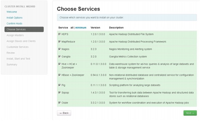
Choose Services
HDP is made up of a number of components. See Understand the Basics for more information.
1.
2.
Figure 77 Choosing Services for the Cluster
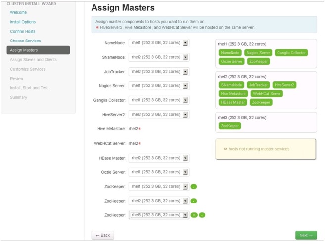
Assign Masters
The Ambari install wizard attempts to assign the master nodes for various services that have been selected for the appropriate hosts in the cluster. Figure 78 shows the current service assignments by the host, the hostname and its number of CPU cores and RAM size.
1.
Note
2.
Figure 78 Assigning Master Components
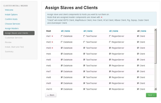
Assign Slaves and Clients
The Ambari install wizard attempts to assign the slave components (DataNodes, TaskTrackers, and RegionServers) to appropriate hosts in the cluster. Reconfigure the service assignment to match Figure 79:
1.
2.
3.
Figure 79 Assigning Slave and Client Components to Hosts
Customize Services
Customize Services window in the cluster install wizard presents a number of configuration settings to manage Hadoop components. The configuration settings can be done based on your requirements under each of the tabs as shown in Figure 132. This window shows the default settings for each of the configuration options, but you can modify the settings to meet specific requirements.
Following are the configurations available in the cluster install wizard:
•
•
The following sections provide details of each of these configurations.
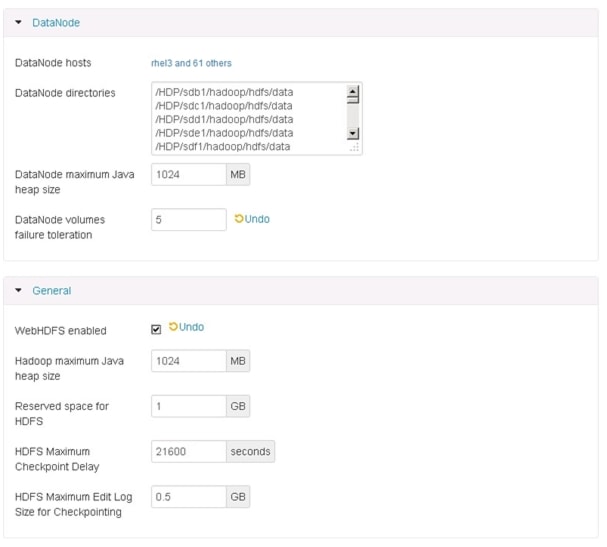
HDFS
Update the HDFS configurations as shown in Table 7, and Figure 80 and Figure 81:
Table 7 HDFS Configurations
NameNode Java Heap Size
4GB
Reserved space for HDFS
4GB
DataNode Volumes Failure Toleration
5
Figure 80 Customize Services - HDFS Configuration Window Part 1
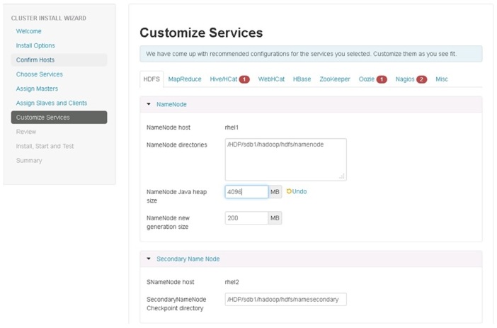
Figure 81 Customize Services - HDFS Configuration Window Part 2
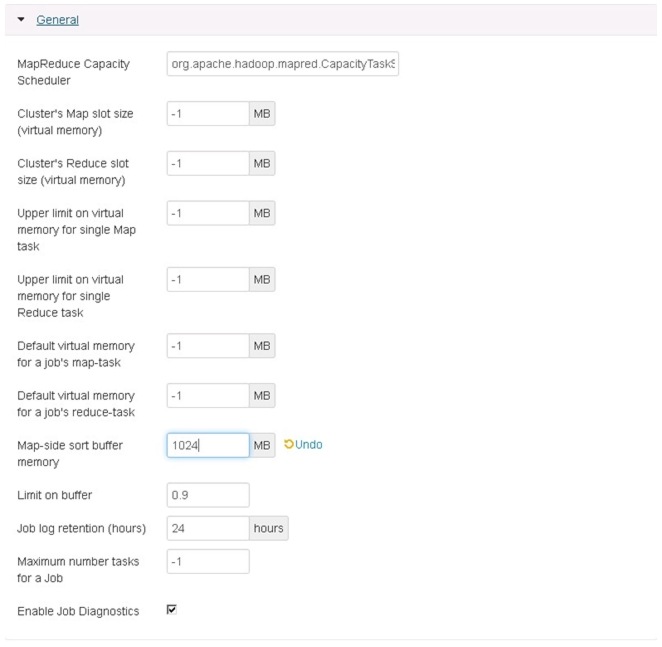
MapReduce
Update the MapReduce configuration as shown in Table 8, and Figure 82 and Figure 83:
Figure 82 Customize Services - MapReduce Configuration Window Part 1
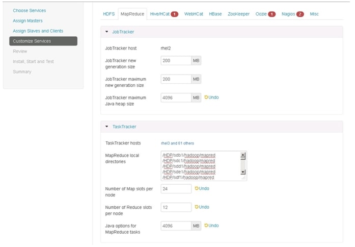
Figure 83 Customize Services - MapReduce Configuration Window Part 2
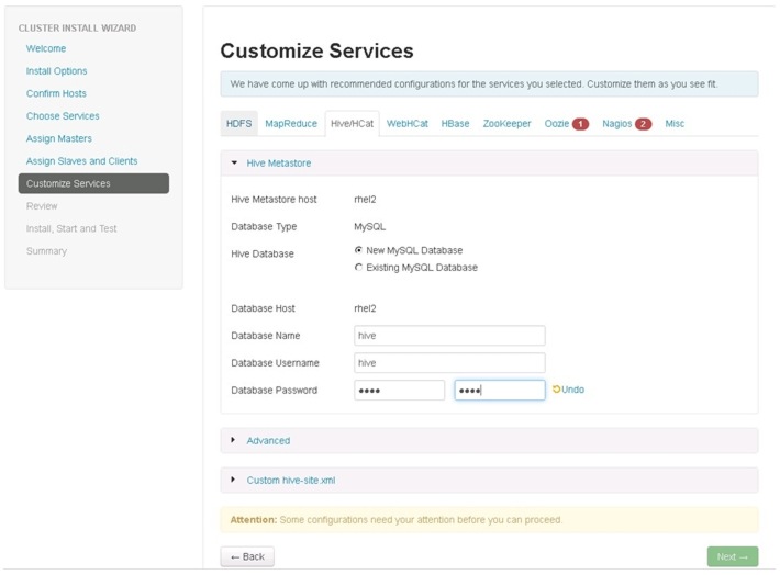
Hive/HCat
Enter the hive database password as per the organizational policy as shown in Figure 84.
Figure 84 Customize Services - Hive/HCat Window
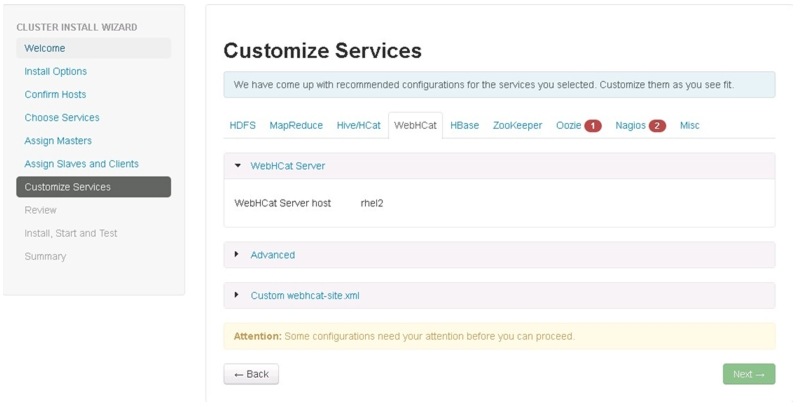
WebHCat
We can restore the default settings, no changes needed as shown in Figure 85.
Figure 85 Customize Services - WebHcat Configuration
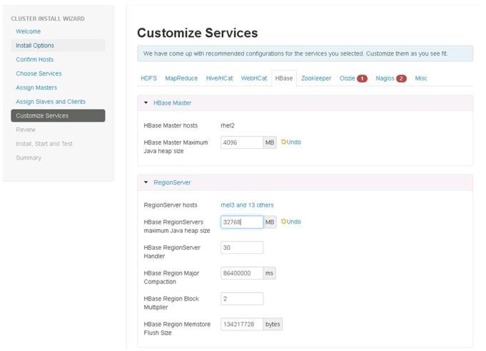
HBase
Update the HBase configurations as shown in Table 9, and Figure 86:
Table 9 HBase Configurations
HBase Master Maximum Java Heap Size
4GB
HBase RegionServers Maximum Java Heap Size
32GB
Figure 86 Customize Services - HBase Configuration Window
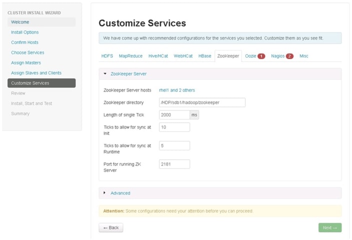
ZooKeeper
We can restore the default settings in the ZooKeeper window, no changes needed as shown in Figure 85.
Figure 87 Customize Services - ZooKeeper Window
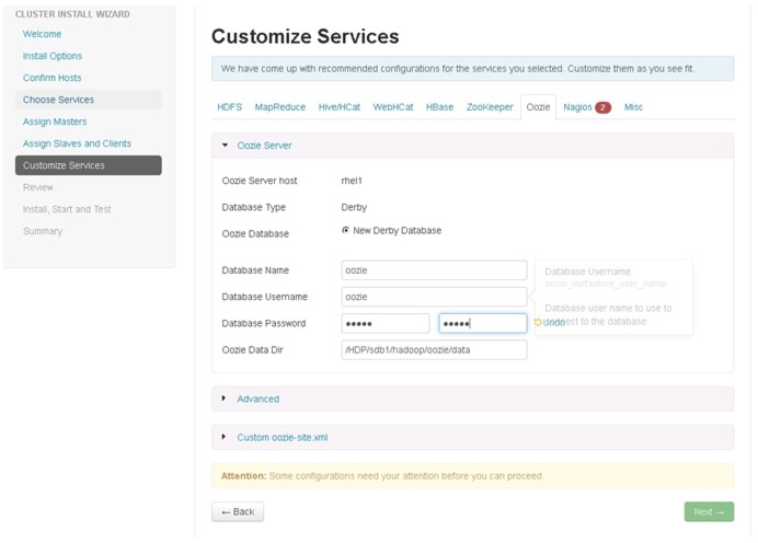
Oozie
Enter the Oozie database password as per the organizational policy as shown in Figure 88.
Figure 88 Customize Services - Oozie Window
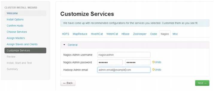
Nagios
Update the Nagios configuration as shown in Figure 89.
Enter the following in the Nagios window:
•
•
Figure 89 Customize Services - Nagios Window
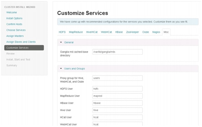
Misc
We can restore the default settings in the Misc window, no changes needed as shown in Figure 90.
Figure 90 Customize Services - Misc Window
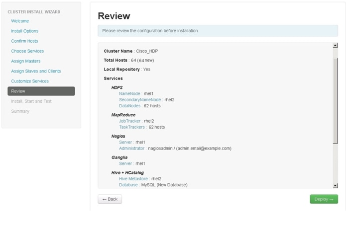
Review
Make sure the Review window shows all the configurations that you have done. Then click Deploy as shown in Figure 91. If any changes are to be made, use the left navigation bar to return to the appropriate screen.
Figure 91 Review Window
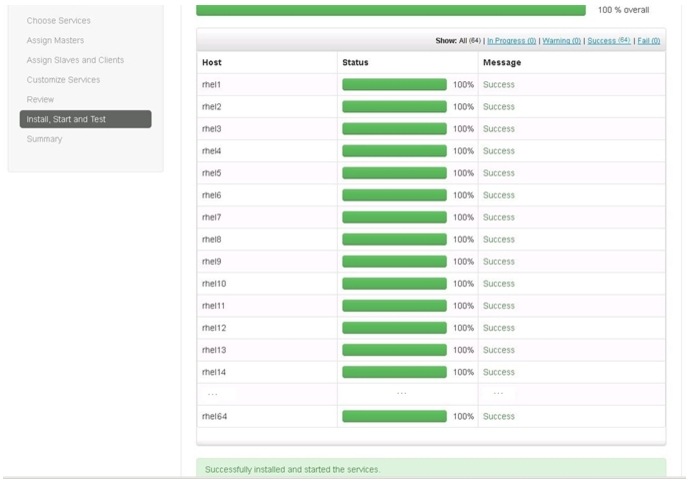
The installation process is shown by the progress indicator as shown in Figure 92. Each component when installed, gets started with a simple test which is run on each of the components. The overall status of the installed components are shown by the progress bar besides every host.
To see the specific information on what tasks have been completed per host, click the link in the Message column for the appropriate host. In the Tasks pop-up, select individual task to see the related log files. Select filter conditions by using the drop-down list. To see a larger version of the log contents, click Open. And to copy the contents to the clipboard, click Copy.
Depending on the components being installed per host, the entire process may take 30 or more minutes.
Click Next, when successfully installed and started the services message at the bottom of window appears as shown in Figure 92.
Figure 92 Cluster Install Wizard - Install, Start and Test Window
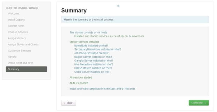
Summary of Installation Process
The summary page shows the accomplished tasks after the completion of cluster installation.
Figure 93 Cluster Install Wizard- Summary Window
Conclusion
Hadoop has become a popular data management application across all the verticals. The Cisco CPA for Big Data for HDP offers a dependable deployment model for enterprise Hadoop that offer a fast and predictable path for businesses to unlock the value in big data.
The configuration details provided in this document can be extended to clusters of various sizes depending on application demands. Up to 160 servers (10 racks) can be supported without an additional switching in a single UCS domain. Each additional rack requires two Cisco Nexus 2232PP 10GigE Fabric Extenders and 16 Cisco UCS C240M3 Rack-Mount Servers. Scaling beyond 10 racks (160 servers) can be implemented by interconnecting multiple UCS domains using Nexus 6000/7000 Series switches. The solution is scalable to thousands of servers and to hundreds of petabytes storage, and is managed from a single pane using Cisco UCS Central.
Bill of Material
This section provides the hardware and software components used in the design setup for deploying the 64-node High Performance Cluster.
Table 10 describes the BOM for the master rack; Table 11 describes the BOM for expansion racks (rack 2 to 4); and Table 12 and Table 13 describe the BOM for the software components
Table 12 RedHat Enterprise Linux License
RHEL-2S-1G-3A
Red Hat Enterprise Linux
64
CON-ISV1-RH2S1G3A
3 year Support for Red Hat Enterprise Linux
64
 Feedback