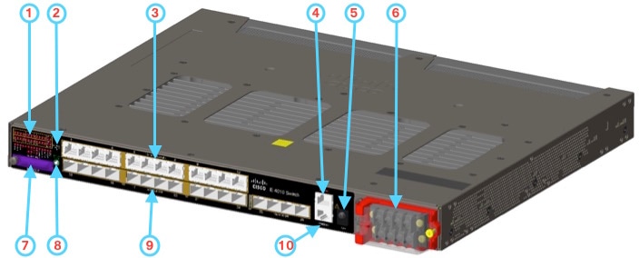
Switch Models
|
Model |
Total Ports |
Uplinks |
SFP Fiber Ports |
Copper 10/100/1000PoE/PoE+ Ports 1 |
Default Software License |
Power Supplies |
|---|---|---|---|---|---|---|
|
IE-4010-16S12P |
28 |
4 SFP (100MB/1G) |
12 (100/1000M |
12 (10/100/1000M) |
LAN Base2 |
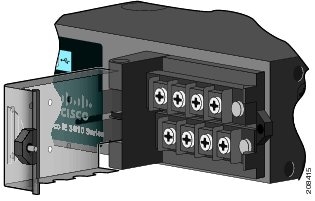
Support for 2 field-replaceable, redundant AC or DC power supplies. |
|
IE-4010-4S24P |
28 |
4 SFP (100MB/1G) |
— |
24 (10/100/1000M) |
LAN Base |
Support for 2 field-replaceable, redundant AC or DC power supplies. |
 Note |
1All copper Gigabit Ethernet interfaces support speed negotiation to 10/100/1000 mbps and duplex negotiation.Ethernet 4010 Series. |
Note |
2Can be upgraded to IP Services at a fee. IP Services License Product Numbers are the following: L-IE4000-RTU= (Electronic SW License for IE4000 Switches) |


 Feedback