Power-Supply Modules
|
Model |
Description |
|---|---|
|
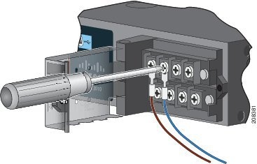
PWR-RGD-LOW-DC-H |
Low-voltage DC. For detailed specifications, see the IE 4010 Data Sheet. |
|
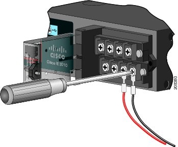
PWR-RGD-AC-DC-H |
High-voltage AC or DC. For detailed specifications, see the Cisco Industrial Ethernet 4010 Series Switches Data Sheet. |
|
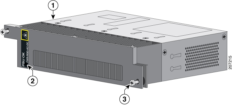
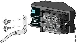
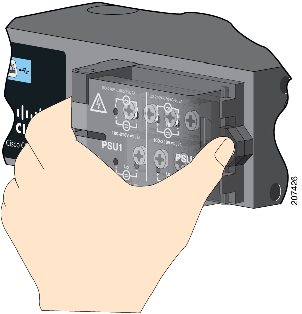
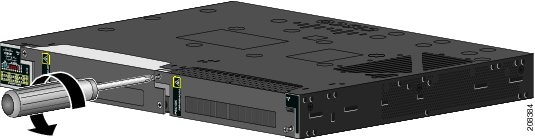
1 |
Power-supply module |
|
2 |
PSU OK LED |
|
3 |
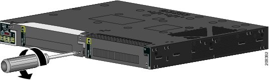
Captive screw |
|
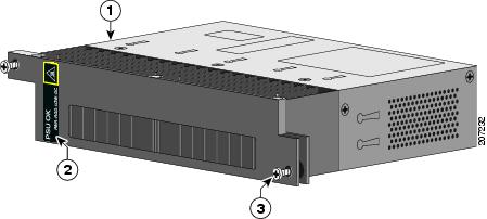
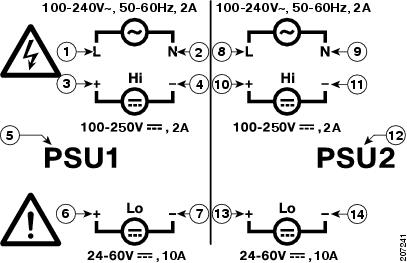
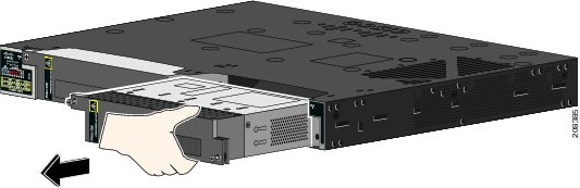
1 |
Power-supply module |
|
2 |
PSU OK LED |
|
3 |
Captive screw |
 Note |
Power Supplies with the -H suffix are required for hazardous environment installations. Non hazardous environments may use either -H or non -H supplies. |
For a description of the PSU OK LEDs, see Power-Supply Module LEDs.


 Feedback