Configuring Bidirectional Forwarding Detection

This document describes how to enable the Bidirectional Forwarding Detection (BFD) protocol. BFD is a detection protocol that is designed to provide fast forwarding path failure detection times for all media types, encapsulations, topologies, and routing protocols.

BFD provides a consistent failure detection method for network administrators, in addition to fast forwarding path failure detection. Because the network administrator can use BFD to detect forwarding path failures at a uniform rate, rather than the variable rates for different routing protocol hello mechanisms, network profiling and planning will be easier, and reconvergence time will be consistent and predictable.

Prerequisites for Bidirectional Forwarding Detection

  • All participating switches must enable Cisco Express Forwarding and IP routing.

  • Before BFD is deployed on a switch, it is necessary to configure one of the IP routing protocols that are supported by BFD. You should implement fast convergence for the routing protocol that you are using. See IP routing documentation for your version of Cisco IOS software for information on configuring fast convergence. See the "Restrictions for Bidirectional Forwarding Detection" section for more information on BFD routing protocol support in Cisco IOS software.

Restrictions for Bidirectional Forwarding Detection

  • BFD works only for directly connected neighbors. BFD neighbors must be no more than one IP hop away. BFD does not support Multihop configurations for any protocol except IPv4 static routes.


    Note


    The above restriction is applicable only for Cisco Catalyst 9500 Series Switches - High Performance


  • BFD support is not available for all platforms and interfaces. To confirm if a specific platform or interface has BFD support and to obtain the most accurate platform and hardware restrictions, see the Cisco IOS software release notes for your software version.

  • The QoS policy for self-generated packets does not match BFD packets.

  • The class class-default command matches BFD packets. So, you must make sure of the availability of appropriate bandwidth to prevent dropping of BFD packets due to oversubscription.

  • BFD HA is not supported.

  • When you use YANG operational models to delete individual BFD interval values, the whole BFD interval configuration gets deleted.

Information About Bidirectional Forwarding Detection

The following sections provide information about bidirectional forwarding detection.

BFD Operation

BFD provides a low-overhead, short-duration method of detecting failures in the forwarding path between two adjacent devices. These devices include the interfaces, data links, and forwarding planes.

BFD is a detection protocol that you enable at the interface and routing protocol levels. Cisco supports BFD asynchronous mode. BFD asychronous mode depends on the sending of BFD control packets between two systems to activate and maintain BFD neighbor sessions between devices. Therefore, in order to create a BFD session, you must configure BFD on both systems (or BFD peers). A BFD session is created once BFD is enabled on the interfaces and at the device level for the appropriate routing protocols. BFD timers are negotiated, and the BFD peers begin to send BFD control packets to each other at the negotiated interval.

Starting with Cisco IOS XE Gibraltar 16.11.1 release, the BFD protocol can be configured between PE-CE (Provider Edge-Customer Edge) and PE-P (Provider Edge- Provider) in an MPLS network. This enhancement is not supported on the C9500-12Q, C9500-16X, C9500-24Q, C9500-40X models of the Cisco Catalyst 9500 Series Switches.

Neighbor Relationships

BFD provides fast BFD peer failure detection times independently. This is independent of all media types, encapsulations, topologies, and routing protocols such as BGP, EIGRP, IS-IS, and OSPF. BFD sends rapid failure detection notices to the routing protocols in the local device to initiate the routing table recalculation process. In this way, BFD contributes to greatly reduced overall network convergence time. The figure below shows a simple network with two devices running OSPF and BFD. When OSPF discovers a neighbor (1), it sends a request to the local BFD process. It initiates a BFD neighbor session with the OSPF neighbor device (2). The BFD neighbor session with the OSPF neighbor device is established (3).

Figure 1. BFD Process on a Network Configured with OSPF
Neighbor relationships are established using BFD

The figure below shows what happens when a failure occurs in the network (1). The BFD neighbor session with the OSPF neighbor device is torn down (2). BFD notifies the local OSPF process that the BFD neighbor is no longer reachable (3). The local OSPF process tears down the OSPF neighbor relationship (4). If an alternative path is available, the devices immediately start converging on it.

Figure 2. BFD Process During a Network Failure
Neighbor sessions removed using BFD during network failure

A routing protocol must register with BFD for every neighbor it acquires. Once a neighbor is registered, BFD initiates a session with the neighbor if a session does not already exist.

OSPF registers with BFD when:

  • A neighbor finite state machine (FSM) transitions to full state.

  • Both OSPF BFD and BFD are enabled.

On broadcast interfaces, OSPF establishes a BFD session only with the designated router (DR) and backup designated router (BDR). The session is not established between any two devices in a DROTHER state.

BFD Detection of Failures

Once a BFD session is established and timer negations are complete, BFD peers send BFD control packets. The packets act in the same manner as an IGP hello protocol to detect liveliness, except at a more accelerated rate. The following information should be noted:

  • BFD is a forwarding path failure detection protocol. BFD detects a failure, but the routing protocol must act to bypass a failed peer.

  • Starting with Cisco IOS XE Denali 16.3.1, Cisco devices support BFD version 0. Devices use one BFD session for multiple client protocols in the implementation. For example, if a network is running OSPF and EIGRP across the same link to the same peer, only one BFD session is established. BFD shares session information with both routing protocols.

BFD Version Interoperability

All BFD sessions come up as Version 1 by default and are interoperable with Version 0. The system automatically performs BFD version detection, and BFD sessions between neighbors run in the highest common BFD version between neighbors. For example, if one BFD neighbor is running BFD Version 0 and the other BFD neighbor is running Version 1, the session runs BFD Version 0. The output from the show bfd neighbors [details ] command verifies which BFD version a BFD neighbor is running.

See the "Example Configuring BFD in an EIGRP Network with Echo Mode Enabled by Default" for an example of BFD version detection.

BFD Session Limits

Starting with Cisco IOS XE Denali 16.3.1, the number of BFD sessions that can be created has been increased to 100.

BFD Support for BGP IPv6 Neighbors

Starting with the Cisco IOS XE Gibraltar 16.11.1 release, BFD can be used for BGP neighbors that have an IPv6 address on Cisco Catalyst 9500 Series Switches - High Performance.

BFD also detects fast forwarding path failure of BGP neighbors that have an IPv6 address. BFD is a detection protocol that is designed to provide fast forwarding path failure detection times. BFD works for all media types such as encapsulations, topologies, and different routing protocols. BFD provides faster reconvergence time for BGP after a forwarding path failure.

BFD Support for GRE IP Tunnel

Starting with the Cisco IOS XE Gibraltar 16.11.1 release, BFD forwarding on point-to-point IPv4, IPv6, and generic routing encapsulation (GRE) tunnels is supported on Cisco Catalyst 9500 Series Switches - High Performance.

Only numbered interfaces are allowed. When the tunnel type changes from a supported tunnel to an unsupported one, BFD sessions are brought down for that tunnel and the BFD configuration is removed from the interface.

BFD detection time depends on the topology and infrastructure. For a single-hop IP tunnel that deploys across physically adjacent devices, the 150 ms (that is, a hello interval of 50 ms with up to three retries) detection rate applies. However, when the source and destination endpoints of the tunnel are not connected back-to-back, the 150-ms detection rate is not guaranteed.

BFD uses the IP address that is configured on the tunnel interface. It does not use the tunnel source and destination addresses.

BFD Support for Nonbroadcast Media Interfaces

Starting from Cisco IOS XE Denali 16.3.1, the BFD feature is supported on routed, SVI, and L3 port channels. The bfd interval command must be configured on the interface to initiate BFD monitoring.

BFD Support for Nonstop Forwarding with Stateful Switchover

Typically, when a networking device restarts, all routing peers of that device detect that the device went down and then came back up. This transition results in a routing flap, which could spread across multiple routing domains. Routing flaps that are caused by routing restarts create routing instabilities, which are detrimental to the overall network performance. Nonstop forwarding (NSF) helps to suppress routing flaps in devices enabled with stateful switchover (SSO), thus reducing network instability.

NSF allows for the forwarding of data packets to continue along known routes while the routing protocol information is restored after a switchover. With NSF, peer networking devices do not experience routing flaps. Data traffic is forwarded through intelligent line cards or dual forwarding processors while the standby RP assumes control from the failed active RP during a switchover. One key to NSF operation is the ability of line cards and forwarding processors to remain up through a switchover. They remain current with the Forwarding Information Base (FIB) on the active RP.

In devices that support dual RPs, SSO establishes one of the RPs as the active processor; the other RP is designated as the standby processor. SSO synchronizes information between the active and standby processor. A switchover from the active to the standby processor occurs when the active RP fails, it is removed from the networking device, or it is manually taken down for maintenance.

BFD Intervals Based on Interface

The following table displays the relationship between interfaces, BFD intervals and the Timeout values that must be configured on the interfaces:


Note


The BFD intervals that are listed below are applicable only for the Cisco Catalyst 9500 High Performance Series Switches.


Types of Interface

Minimum Supported Values for BFD Timer

Standalone

Redundant Systems

Physical Interface

50ms * 3

250ms * 3

L3 Subinterface

50ms * 3

750ms * 3

Switch Virtual Interface (SVI)

100ms * 3

750ms * 3

Layer 3 Portchannel

250ms * 3

750ms * 3

Layer 3 Portchannel Subinterface

250ms * 3

750ms * 3


Note


On the Cisco Cisco Catalyst 9500X Series Switches, in fabric based networks like SDA, BFD timer for redundant systems is 750ms * 3 for both physical and virtual interfaces.


BFD Support for Stateful Switchover

The BFD protocol provides short-duration detection of failures in the path between adjacent forwarding engines. In network deployments that use dual RP routers or switches (to provide redundancy), the routers have a graceful restart mechanism. This mechanism protects the forwarding state during a switchover between the active RP and the standby RP.

The dual RPs have variable switchover times that depend on the ability of the hardware to detect a communication failure. When BFD is running on the RP, some platforms are not able to detect a switchover before the BFD protocol times out. These platforms are referred to as slow switchover platforms.

BFD Support for Static Routing

Unlike dynamic routing protocols, such as OSPF and BGP, static routing has no method of peer discovery. Therefore, when BFD is configured, the reachability of the gateway depends on the state of the BFD session to the specified neighbor. Unless the BFD session is up, the gateway for the static route is unreachable, and the affected routes are not installed in the appropriate Routing Information Base (RIB).

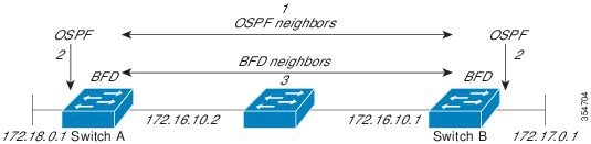
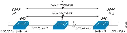
To successfully establish a BFD session, BFD must be configured on the interface on the peer. There must be a BFD client that is registered on the peer for the address of the BFD neighbor. When an interface is used by dynamic routing protocols, the latter requirement is met by configuring the routing protocol instances on each neighbor for BFD. When an interface is used exclusively for static routing, this requirement must be met by configuring static routes on the peers.

If a BFD configuration is removed from the remote peer while the BFD session is in the up state, the updated state of the BFD session is not signaled to IPv4 static. This causes the static route to remain in the RIB. The only workaround is to remove the IPv4 static BFD neighbor configuration so that the static route no longer tracks BFD session state. Also, if you change the encapsulation type on a serial interface to one that is unsupported by BFD, BFD will be in a down state on that interface. The workaround is to shut down the interface, change to a supported encapsulation type, and then reconfigure BFD.

A single BFD session can be used by an IPv4 static client to track the reachability of next hops through a specific interface. You can assign a BFD group for a set of BFD-tracked static routes. Each group must have one active static BFD configuration, one or more passive BFD configurations, and the corresponding BFD tracked static routes. Nongroup entries are BFD-tracked static routes for which a BFD group is not assigned. A BFD group must accommodate static BFD configurations that can be part of different VRFs. Effectively, the passive static BFD configurations need not be in the same VRF as that of the active configuration.

For each BFD group, there can be only one active static BFD session. You can configure the active BFD session by adding a static BFD configuration and a corresponding static route that uses the BFD configuration. The BFD session in a group is created only when there is an active static BFD configuration and the static route that uses the static BFD configuration. When the active static BFD configuration or the active static route is removed from a BFD group, all the passive static routes are withdrawn from the RIB. Effectively, all the passive static routes are inactive until an active static BFD configuration and a static route to be tracked by the active BFD session are configured in the group.

Similarly, for each BFD group, there can be one or more passive static BFD configurations and their corresponding static routes to be BFD-tracked. Passive static session routes take effect only when the active BFD session state is reachable. Though the active BFD session state of the group is reachable, the passive static route is added to the RIB only if the corresponding interface state is up. When a passive BFD session is removed from a group, it will not affect the active BFD session if one existed, or the BFD group reachability status.

Benefits of Using BFD for Failure Detection

When you deploy any feature, it is important to consider all the alternatives and be aware of any trade-offs.

The closest alternative to BFD, in conventional deployments, is the use of modified failure detection mechanisms for EIGRP, IS-IS, and OSPF routing protocols.

If you set EIGRP hello and hold timers to their absolute minimums, the failure detection rate for EIGRP falls to within a one- to two-second range. If you use fast hellos for Interior Gateway Protocol (IGP) protocols such as IS-IS or OSPF, they reduce their failure detection mechanisms to a minimum of one second.

There are several advantages to implementing BFD over reduced timer mechanisms for routing protocols:

  • Although reducing the EIGRP, IS-IS, and OSPF timers can result in minimum detection timer of one to two seconds, BFD can provide failure detection in less than one second.

  • Because BFD is not tied to any particular routing protocol, it can be used as a generic and consistent failure detection mechanism for EIGRP, IS-IS, and OSPF.

  • Because some parts of BFD can be distributed to the data plane, it can be less CPU-intensive than the reduced EIGRP, IS-IS, and OSPF timers, which exist wholly at the control plane.

How to Configure Bidirectional Forwarding Detection

The following sections provide configurational information about bidirectional forwarding detection.

Configuring BFD Session Parameters on the Interface

To configure BFD on an interface, you must set the baseline BFD session parameters. Repeat the steps in this procedure for each interface over which you want to run BFD sessions to BFD neighbors.

The following procedure shows BFD configuration steps for a physical interface. Please use the corresponding BFD timer values for SVIs and ether-channels respectively.

Procedure

  Command or Action Purpose

Step 1

enable

Example:


Device>enable

Enables privileged EXEC mode.

Enter your password if prompted.

Step 2

configure terminal

Example:


Device#configure terminal

Enters global configuration mode.

Step 3

Perform one of the following steps:

  • ip address ipv4-address mask
  • ipv6 address ipv6-address/mask

Example:

Configuring an IPv4 address for the interface:

Device(config-if)#ip address 10.201.201.1 255.255.255.0
Configuring an IPv6 address for the interface:

Device(config-if)#ipv6 address 2001:db8:1:1::1/32 
Configures an IP address for the interface.

Step 4

bfd interval milliseconds min_rx milliseconds multiplier interval-multiplier

Example:


Device(config-if)#bfd interval 100 min_rx 100 multiplier 3

Enables BFD on the interface.

The BFD interval configuration is removed when the subinterface on which it is configured is removed.

The BFD interval configuration is not removed when:

  • An interface removes an IPv4 address.

  • An interface removes an IPv6 address is removed from an interface.

  • An interface disables IPv6.

  • An interface is shutdown

  • An interface globally or locally disables IPv4 CEF.

  • An interface globally or locally disables IPv6 CEF.

Step 5

end

Example:


Device(config-if)#end

Exits interface configuration mode and returns to privileged EXEC mode.

Configuring BFD Support for Dynamic Routing Protocols

The following sections provide configurational information about BFD support for dynamic routing protocols.

Configuring BFD Support for eBGP

This section describes the procedure for configuring BFD support for BGP. This ensures that BGP is a registered protocol with BFD and receives forwarding path detection failure messages from BFD.

Before you begin

eBGP must be running on all participating routers.

Configure the baseline parameters for BFD sessions on the interfaces over which you want to run BFD sessions to BFD neighbors. See the Configuring BFD Session Parameters on the Interface section for more information.


Note


Output from the show bfd neighbors details command shows the configured intervals.


Procedure
  Command or Action Purpose

Step 1

enable

Example:

Device>enable

Enables privileged EXEC mode.

Enter your password if prompted.

Step 2

configure terminal

Example:

Device#configure terminal

Enters global configuration mode.

Step 3

router bgp as-tag

Example:

Device(config)#router bgp tag1

Specifies a BGP process and enters router configuration mode.

Step 4

neighbor ip-address fall-over bfd

Example:

Device(config-router)#neighbor 172.16.10.2 fall-over bfd

Enables BFD support for fallover.

Step 5

end

Example:

Device(config-router)#end

Exits router configuration mode and returns the router to privileged EXEC mode.

Step 6

show bfd neighbors [details ]

Example:

Device#show bfd neighbors detail

(Optional) Verifies that the BFD neighbor is active and displays the routing protocols that BFD has registered.

Step 7

show ip bgp neighbor

Example:

Device#show ip bgp neighbor

(Optional) Displays information about BGP and TCP connections to neighbors.

Configuring BFD Support for EIGRP

This section describes the procedure for configuring BFD support for EIGRP. This ensures EIGRP is a registered protocol with BFD and receives forwarding path detection failure messages from BFD. There are two methods for enabling BFD support for EIGRP:

  • You can enable BFD for all interfaces for which EIGRP is routing by using the bfd all-interfaces command in router configuration mode.

  • You can enable BFD for a subset of the interfaces for which EIGRP is routing by using the bfd interface type number command in router configuration mode.

Before you begin
  • EIGRP must be running on all participating routers.

  • Configure the baseline parameters for BFD sessions on the interfaces over which you want to run BFD sessions to BFD neighbors. See the "Configuring BFD Session Parameters on the Interface" section for more information.


Note


Output from the show bfd neighbors details command shows the configured intervals.


Procedure
  Command or Action Purpose

Step 1

enable

Example:

Device>enable

Enables privileged EXEC mode.

Enter your password if prompted.

Step 2

configure terminal

Example:

Device#configure terminal

Enters global configuration mode.

Step 3

router eigrp as-number

Example:

Device(config)#router eigrp 123

Configures the EIGRP routing process and enters router configuration mode.

Step 4

Do one of the following:

  • bfd all-interfaces
  • bfd interface type number
Example:

Device(config-router)#bfd all-interfaces
Example:

Device(config-router)#bfd interface GigabitFastEthernet 1/0/1

Enables BFD globally on all interfaces that are associated with the EIGRP routing process.

Or

Enables BFD on a per-interface basis for one or more interfaces that are associated with the EIGRP routing process.

Step 5

end

Example:

Device(config-router)#end

Exits router configuration mode and returns the router to privileged EXEC mode.

Step 6

show bfd neighbors [details ]

Example:

Device#show bfd neighbors details

(Optional) Verifies that the BFD neighbor is active and displays the routing protocols that BFD has registered.

Step 7

show ip eigrp interfaces [type number ] [as-number ] [detail ]

Example:

Device#show ip eigrp interfaces detail

(Optional) Displays the interfaces for which BFD support for EIGRP is enabled.

Configuring BFD Support for IS-IS

This section describes the procedures for configuring BFD support for IS-IS so that IS-IS is a registered protocol with BFD and will receive forwarding path detection failure messages from BFD. There are two methods for enabling BFD support for IS-IS:

  • You can enable BFD for all of the interfaces on which IS-IS is supporting IPv4 routing by using the bfd all-interfaces command in router configuration mode. You can then disable BFD for one or more of those interfaces using the isis bfd disable command in interface configuration mode.

  • You can enable BFD for a subset of the interfaces for which IS-IS is routing by using the isis bfd command in interface configuration mode.

To configure BFD support for IS-IS, perform the steps in one of the following sections:

Prerequisites
  • IS-IS must be running on all participating devices.

  • The baseline parameters for BFD sessions on the interfaces that you want to run BFD sessions to BFD neighbors over must be configured. See the "Configuring BFD Session Parameters on the Interface" section for more information.

Configuring BFD Support for IS-IS for All Interfaces

To configure BFD on all IS-IS interfaces that support IPv4 routing, perform the steps in this section.

Procedure
  Command or Action Purpose

Step 1

enable

Example:

Device>enable

Enables privileged EXEC mode.

Enter your password if prompted.

Step 2

configure terminal

Example:

Device#configure terminal

Enters global configuration mode.

Step 3

router isis area-tag

Example:

Device(config)#router isis tag1

Specifies an IS-IS process and enters router configuration mode.

Step 4

bfd all-interfaces

Example:

Device(config-router)#bfd all-interfaces

Enables BFD globally on all interfaces that are associated with the IS-IS routing process.

Step 5

exit

Example:

Device(config-router)#exit

(Optional) Returns the device to global configuration mode.

Step 6

interface type number

Example:

Device(config)#interface fastethernet 6/0

(Optional) Enters interface configuration mode.

Step 7

ip router isis [ tag ]

Example:

Device(config-if)#ip router isis tag1

(Optional) Enables support for IPv4 routing on the interface.

Step 8

isis bfd [disable ]

Example:

Device(config-if)#isis bfd

(Optional) Enables or disables BFD on a per-interface basis for one or more interfaces that are associated with the IS-IS routing process.

Note


You should use the disable keyword only if you had earlier enabled BFD on all the interfaces that IS-IS is associated with, using the bfd all-interfaces command in configuration mode.

Step 9

end

Example:

Device(config-if)#end

Exits interface configuration mode and returns the device to privileged EXEC mode.

Step 10

show bfd neighbors [details ]

Example:

Device#show bfd neighbors details

(Optional) Displays information that can be used to verify if the BFD neighbor is active and displays the routing protocols that BFD has registered.

Step 11

show clns interface

Example:

Device#show clns interface

(Optional) Displays information that can be used to verify if BFD for IS-IS has been enabled for a specific IS-IS interface that is associated.

Configuring BFD Support for IS-IS for One or More Interfaces

To configure BFD for only one or more IS-IS interfaces, perform the steps in this section.

Procedure
  Command or Action Purpose

Step 1

enable

Example:

Device>enable

Enables privileged EXEC mode.

Enter your password if prompted.

Step 2

configure terminal

Example:

Device#configure terminal

Enters global configuration mode.

Step 3

interface type number

Example:

Device(config)#interface fastethernet 6/0

Enters interface configuration mode.

Step 4

ip router isis [ tag ]

Example:

Device(config-if)#ip router isis tag1

Enables support for IPv4 routing on the interface.

Step 5

isis bfd [disable]

Example:

Device(config-if)#isis bfd

Enables or disables BFD on a per-interface basis for one or more interfaces that are associated with the IS-IS routing process.

Note


You should use the disable keyword only if you enabled BFD on all the interfaces that IS-IS is associated with using the bfd all-interfaces command in router configuration mode.

Step 6

end

Example:

Device(config-if)#end

Exits interface configuration mode and returns the device to privileged EXEC mode.

Step 7

show bfd neighbors [details ]

Example:

Device#show bfd neighbors details

(Optional) Displays information that can help verify if the BFD neighbor is active and displays the routing protocols that BFD has registered.

Step 8

show clns interface

Example:

Device#show clns interface

(Optional) Displays information that can help verify if BFD for IS-IS has been enabled for a specific IS-IS interface that is associated.

Configuring BFD Support for OSPF

This section describes the procedures for configuring BFD support for OSPF so that OSPF is a registered protocol with BFD and will receive forwarding path detection failure messages from BFD. You can either configure BFD support for OSPF globally on all interfaces or configure it selectively on one or more interfaces.

There are two methods for enabling BFD support for OSPF:

  • You can enable BFD for all the interfaces for which OSPF is routing by using the bfd all-interfaces command in router configuration mode. You can disable BFD support on individual interfaces using the ip ospf bfd [disable ] command in interface configuration mode.

  • You can enable BFD for a subset of the interfaces for which OSPF is routing by using the ip ospf bfd command in interface configuration mode.

See the following sections for tasks for configuring BFD support for OSPF:

Configuring BFD Support for OSPF for All Interfaces

To configure BFD for all OSPF interfaces, perform the steps in this section.

If you do not want to configure BFD on all OSPF interfaces and would rather configure BFD support specifically for one or more interfaces, see the "Configuring BFD Support for OSPF for One or More Interfaces" section.

Before you begin
  • OSPF must be running on all participating devices.

  • The baseline parameters for BFD sessions on the interfaces over which you want to run BFD sessions to BFD neighbors must be configured. See the "Configuring BFD Session Parameters on the Interface" section for more information.

Procedure
  Command or Action Purpose

Step 1

enable

Example:

Device>enable

Enables privileged EXEC mode.

Enter your password if prompted.

Step 2

configure terminal

Example:

Device#configure terminal

Enters global configuration mode.

Step 3

router ospf process-id

Example:

Device(config)#router ospf 4

Specifies an OSPF process and enters router configuration mode.

Step 4

bfd all-interfaces

Example:

Device(config-router)#bfd all-interfaces

Enables BFD globally on all interfaces that are associated with the OSPF routing process.

Step 5

exit

Example:

Device(config-router)#exit

(Optional) Returns the device to global configuration mode. Enter this command only if you want to perform Step 7 to disable BFD for one or more interfaces.

Step 6

interface type number

Example:

Device(config)#interface fastethernet 6/0

(Optional) Enters interface configuration mode. Enter this command only if you want to perform Step 7 to disable BFD for one or more interfaces.

Step 7

ip ospf bfd [disable ]

Example:

Device(config-if)#ip ospf bfd disable

(Optional) Disables BFD on a per-interface basis for one or more interfaces that are associated with the OSPF routing process.

Note


You should use the disable keyword only if you enabled BFD on all the interfaces that OSPF is associated with using the bfd all-interfaces command in router configuration mode.

Step 8

end

Example:

Device(config-if)#end

Exits interface configuration mode and returns the router to privileged EXEC mode.

Step 9

show bfd neighbors [details ]

Example:

Device#show bfd neighbors detail

(Optional) Displays information that can help verify if the BFD neighbor is active and displays the routing protocols that BFD has registered.

Step 10

show ip ospf

Example:

Device#show ip ospf

(Optional) Displays information that can help verify if BFD for OSPF has been enabled.

Configuring OSPF Support for BFD over IPv4 for One or More Interfaces

To configure BFD on one or more OSPF interfaces, perform the steps in this section.

Procedure
  Command or Action Purpose

Step 1

enable

Example:

Device>enable

Enables privileged EXEC mode.

Enter your password if prompted.

Step 2

configure terminal

Example:

Device#configure terminal

Enters global configuration mode.

Step 3

interface type number

Example:

Device(config)#interface fastethernet 6/0

Enters interface configuration mode.

Step 4

ip ospf bfd [disable ]

Example:

Device(config-if)#ip ospf bfd

Enables or disables BFD on a per-interface basis for one or more interfaces that are associated with the OSPF routing process.

Note


Use the disable keyword only if you enable BFD on all the interfaces that OSPF is associated with using the bfd all-interfaces command in router configuration mode.

Step 5

end

Example:

Device(config-if)#end

Exits interface configuration mode and returns the device to privileged EXEC mode.

Step 6

show bfd neighbors [details ]

Example:

Device#show bfd neighbors details

(Optional) Displays information that can help verify if the BFD neighbor is active and displays the routing protocols that BFD has registered.

Note


If hardware-offloaded BFD sessions are configured with Tx and Rx intervals that are not multiples of 50 ms, the hardware intervals are changed. However, output from the show bfd neighbors details command displays only the configured intervals, not the interval values that change.

Step 7

show ip ospf

Example:

Device#show ip ospf

(Optional) Displays information that can help verify if BFD support for OSPF has been enabled.

Configuring BFD Support for HSRP

Perform this task to enable BFD support for Hot Standby Router Protocol (HSRP.) Repeat the steps in this procedure for each interface over which you want to run BFD sessions to HSRP peers.

HSRP supports BFD by default. If HSRP support for BFD has been manually disabled, you can reenable it at the device level to enable BFD support globally for all interfaces or on a per-interface basis at the interface level.

Before you begin
  • HSRP must be running on all participating devices.

  • Cisco Express Forwarding must be enabled.

Procedure
  Command or Action Purpose

Step 1

enable

Example:

Device>enable

Enables privileged EXEC mode.

Enter your password if prompted.

Step 2

configure terminal

Example:

Device#configure terminal

Enters global configuration mode.

Step 3

ip cef [distributed ]

Example:

Device(config)#ip cef

Enables Cisco Express Forwarding or distributed Cisco Express Forwarding.

Step 4

interface type number

Example:

Device(config)#interface FastEthernet 6/0

Enters interface configuration mode.

Step 5

ip address ip-address mask

Example:

Device(config-if)#ip address 10.1.0.22 255.255.0.0

Configures an IP address for the interface.

Step 6

standby [group-number ] ip [ip-address [secondary ]]

Example:

Device(config-if)#standby 1 ip 10.0.0.11

Activates HSRP.

Step 7

standby bfd

Example:

Device(config-if)#standby bfd

(Optional) Enables HSRP support for BFD on the interface.

Step 8

exit

Example:

Device(config-if)#exit

Exits interface configuration mode.

Step 9

standby bfd all-interfaces

Example:

Device(config)#standby bfd all-interfaces

(Optional) Enables HSRP support for BFD on all interfaces.

Step 10

exit

Example:

Device(config)#exit

Exits global configuration mode.

Step 11

show standby neighbors

Example:

Device#show standby neighbors

(Optional) Displays information about HSRP support for BFD.

Configuring BFD for BGP IPv6 Neighbors

When it has been verified that BFD neighbors are up, the show bgp ipv6 unicast neighbors command indicates that BFD is being used to detect fast fallover on the specified neighbor. The following steps show how to configure BFD for BGP IPv6 neighbors:

Procedure
  Command or Action Purpose

Step 1

enable

Example:
Device>enable

Enables privileged EXEC mode.

Enter your password if prompted.

Step 2

configure terminal

Example:
Device#configure  terminal

Enters global configuration mode.

Step 3

ipv6 unicast-routing

Example:
Device(config)#ipv6 unicast-routing

Enables the forwarding of IPv6 unicast datagrams.

Step 4

ipv6 cef

Example:
Device(config)#ipv6 cef

Enables Cisco Express Forwarding for IPv6.

Step 5

interface type-number

Example:
Device(config)#interface fastethernet 0/1

Configures an interface type and number.

Step 6

ipv6 address ipv6-address / prefix-length

Example:
Device(config-if)#ipv6 address 2001:DB8:1:1::1/64

Configures an IPv6 address and enables IPv6 processing on an interface.

Step 7

bfd interval milliseconds min_rx milliseconds multiplier multiplier-value

Example:
Device(config-if)#bfd interval 500 min_rx 500 multiplier 3

Sets the baseline BFD session parameters on an interface.

Step 8

no shutdown

Example:
Device(config-if)#no shutdown

Restarts an interface.

Step 9

exit

Example:
Device(config-if)#exit

Exits interface configuration mode and enters global configuration mode.

Step 10

router bgp autonomous-system-number

Example:
Device(config)#router bgp 40000

Enters router configuration mode for the specified routing process.

Step 11

no bgp default ipv4-unicast

Example:
Device(config-router)#no bgp default ipv4-unicast

Disables the default IPv4 unicast address family for establishing peering sessions.

We recommend configuring this command in the global scope.

Step 12

address-family ipv6 [ vrf vrf-name] [ unicast | multicast | vpnv6]

Example:
Device(config-router)#address-family ipv6

Enters address family configuration mode and enables IPv6 addressing.

Step 13

neighbor ipv6-address remote-as autonomous-system-number

Example:
Device(config-router-af)#neighbor 2001:DB8:2:1::4 remote-as 45000

Adds the IP address of the neighbor in the specified autonomous system to the IPv6 BGP neighbor table of the local device.

Step 14

neighbor ipv6-addressfall-over bfd

Example:
Device(config-router-af)#neighbor 2001:DB8:2:1::4 fall-over bfd 

Enables BGP to monitor the peering session of an IPv6 neighbor using BFD.

Step 15

end

Example:
Device(config-router-af)#end

Exits address family configuration mode and enters privileged EXEC mode.

Configuring BFD Support for Static Routing

Perform this task to configure BFD support for static routing. Repeat the steps in this procedure on each BFD neighbor. For more information, see the "Example: Configuring BFD Support for Static Routing" section.

Procedure

  Command or Action Purpose

Step 1

enable

Example:


Device>enable

Enables privileged EXEC mode.

Enter your password if prompted.

Step 2

configure terminal

Example:


Device#configure terminal

Enters global configuration mode.

Step 3

interface type number

Example:


Device(config)#interface TenGigabitEthernet1/0/1

Configures an interface and enters interface configuration mode.

Step 4

Perform one of the following steps:

  • ip address ipv4-address mask
  • ipv6 address ipv6-address/mask

Example:

Configuring an IPv4 address for the interface:

Device(config-if)#ip address 10.10.10.1 255.255.255.0
Configuring an IPv6 address for the interface:

Device(config-if)#ipv6 address 2001:db8:1:1::1/32 
Configures an IP address for the interface.

Step 5

bfd interval milliseconds mix_rx milliseconds multiplier interval-multiplier

Example:


Device(config-if)#bfd interval 500 min_rx 500 multiplier 5

Enables BFD on the interface.

The bfd interval configuration is removed when the subinterface on which it is configured is removed.

The bfd interval configuration is not removed when:

  • an IPv4 address is removed from an interface

  • an IPv6 address is removed from an interface

  • IPv6 is disabled from an interface.

  • an interface is shutdown

  • IPv4 CEF is disabled globally or locally on an interface.

  • IPv6 CEF is disabled globally or locally on an interface.

Step 6

exit

Example:


Device(config-if)#exit

Exits interface configuration mode and returns to global configuration mode.

Step 7

ip route static bfd interface-type interface-number ip-address [group group-name [passive]]

Example:


Device(config)#ip route static bfd TenGigabitEthernet1/0/1 10.10.10.2 

Specifies a static route BFD neighbor.

  • The interface-type , interface-number , and ip-address arguments are required because BFD support exists only for directly connected neighbors.

Step 8

ip route [vrf vrf-name] prefix mask {ip-address | interface-type interface-number [ip-address]} [dhcp] [distance] [name next-hop-name] [permanent | track number] [tag tag]

Example:


Device(config)#ip route 10.0.0.0 255.0.0.0 TenGigabitEthernet1/0/1 10.10.10.2 

Specifies a static route BFD neighbor.

Step 9

exit

Example:


Device(config)#exit

Exits global configuration mode and returns to privileged EXEC mode.

Step 10

show ip static route

Example:


Device#show ip static route

(Optional) Displays static route database information.

Step 11

show ip static route bfd

Example:


Device#show ip static route bfd 

(Optional) Displays information about the static BFD configuration from the configured BFD groups and nongroup entries.

Step 12

exit

Example:


Device#exit

Exits privileged EXEC mode and returns to user EXEC mode.

Configuring BFD Echo Mode

BFD echo mode is enabled by default, but you can disable it such that it can run independently in each direction.

BFD echo mode works with asynchronous BFD. Echo packets are sent by the forwarding engine and forwarded back along the same path in order to perform detection--the BFD session at the other end does not participate in the actual forwarding of the echo packets. The echo function and the forwarding engine are responsible for the detection process; therefore, the number of BFD control packets that are sent out between two BFD neighbors is reduced. In addition, because the forwarding engine is testing the forwarding path on the remote (neighbor) system without involving the remote system, there is an opportunity to improve the interpacket delay variance, thereby achieving quicker failure detection times than when using BFD Version 0 with BFD control packets for the BFD session.

Echo mode is described as without asymmetry when it is running on both sides (both BFD neighbors are running echo mode).

Prerequisites

  • BFD must be running on all participating devices.

  • Before using BFD echo mode, you must disable the sending of Internet Control Message Protocol (ICMP) redirect messages by entering the no ip redirects command, in order to avoid high CPU utilization.

  • The baseline parameters for BFD sessions on the interfaces over which you want to run BFD sessions to BFD neighbors must be configured. See the Configuring BFD Session Parameters on the Interface section for more information.

Restrictions

BFD echo mode does not work with Unicast Reverse Path Forwarding (uRPF) configuration. If BFD echo mode and uRPF configurations are enabled, then the sessions will flap.

Disabling BFD Echo Mode Without Asymmetry

The steps in this procedure show how to disable BFD echo mode without asymmetry—no echo packets will be sent by the device, and the device will not forward BFD echo packets that are received from any neighbor devices.

Repeat the steps in this procedure for each BFD Device.

Procedure
  Command or Action Purpose

Step 1

enable

Example:

Device>enable

Enables privileged EXEC mode.

Enter your password if prompted.

Step 2

configure terminal

Example:

Device#configure terminal

Enters global configuration mode.

Step 3

no bfd echo

Example:

Device(config)#no bfd echo

Disables BFD echo mode.

Use the no form to disable BFD echo mode.

Step 4

end

Example:

Device(config)#end

Exits global configuration mode and returns to privileged EXEC mode.

Creating and Configuring BFD Templates

You can configure a single-hop template to specify a set of BFD interval values. BFD interval values specified as part of the BFD template are not specific to a single interface.


Note


Configuring BFD-template will disable echo mode.


Configuring a Single-Hop Template

Perform this task to create a BFD single-hop template and configure BFD interval timers.

Procedure
  Command or Action Purpose

Step 1

enable

Example:

Device>enable

Enables privileged EXEC mode.

Enter your password if prompted.

Step 2

configure terminal

Example:

Device#configure terminal

Enters global configuration mode.

Step 3

bfd-template single-hop template-name

Example:

Device(config)#bfd-template single-hop bfdtemplate1

Creates a single-hop BFD template and enters BFD configuration mode.

Step 4

interval min-tx milliseconds min-rx milliseconds multiplier multiplier-value

Example:

Device(bfd-config)#interval min-tx 120 min-rx 100 multiplier 3

Configures the transmit and receive intervals between BFD packets, and specifies the number of consecutive BFD control packets that must be missed before BFD declares that a peer is unavailable.

Step 5

end

Example:

Device(bfd-config)#end

Exits BFD configuration mode and returns the device to privileged EXEC mode.

Monitoring and Troubleshooting BFD

This section describes how to retrieve BFD information for maintenance and troubleshooting. The commands in these tasks can be entered in any order as needed.

This section contains information for monitoring and troubleshooting BFD for the following Cisco platforms:

Monitoring and Troubleshooting BFD

To monitor or troubleshoot BFD, perform one or more of the steps in this section.

Procedure
  Command or Action Purpose

Step 1

enable

Example:

Device>enable

Enables privileged EXEC mode.

Enter your password if prompted.

Step 2

show bfd neighbors [details ]

Example:

Device#show bfd neighbors details

(Optional) Displays the BFD adjacency database.

The details keyword shows all BFD protocol parameters and timers per neighbor.

Step 3

debug bfd [packet | event ]

Example:

Device#debug bfd packet

(Optional) Displays debugging information about BFD packets.

Configuration Example: Configuring BFD for a BGP IPv6 Neighbor

The following example configures FastEthernet interface 0/1 with the IPv6 address 2001:DB8:4:1::1. Bidirectional Forwarding Detection (BFD) is configured for the BGP neighbor at 2001:DB8:5:1::2. BFD will track forwarding path failure of the BGP neighbor and provide faster reconvergence time for BGP after a forwarding path failure.

Device(config)#ipv6 unicast-routing 
Device(config)#ipv6 cef
Device(config)#interface fastethernet 0/1
Device(config-if)#ipv6 address 2001:DB8:4:1::1/64
Device(config-if)#bfd interval 500 min_rx 500 multiplier 3
Device(config-if)#no shutdown
Device(config-if)#exit
Device(config)#router bgp 65000
Device(config-router)#no bgp default ipv4-unicast
Device(config-router)#address-family ipv6 unicast
Device(config-router-af)#neighbor 2001:DB8:5:1::2 remote-as 65001
Device(config-router-af)#neighbor 2001:DB8:5:1::2 fall-over bfd
Device(config-router-af)#end

Feature History for Configuring Bidirectional Forwarding Detection

This table provides release and related information for the features explained in this module.

These features are available in all the releases subsequent to the one they were introduced in, unless noted otherwise.

Release

Feature

Feature Information

Cisco IOS XE Everest 16.5.1a

Bidirectional Forwarding Detection

BFD is a detection protocol that is designed to provide fast forwarding path failure detection times for all media types, encapsulations, topologies, and routing protocols.

Support for this feature was introduced on the C9500-12Q, C9500-16X, C9500-24Q, C9500-40X models of the Cisco Catalyst 9500 Series Switches.

Cisco IOS XE Fuji 16.8.1a

Bidirectional Forwarding Detection

Support for this feature was introduced on the C9500-32C, C9500-32QC, C9500-48Y4C, and C9500-24Y4C models of the Cisco Catalyst 9500 Series Switches.

Cisco IOS XE Gibraltar 16.11.1

BFD forwarding on point-to-point IPv4, IPv6, and GRE tunnels

Suppprt for BFD forwarding on point-to-point IPv4, IPv6, and generic routing encapsulation (GRE) tunnels

Support for this feature was introduced on the C9500-32C, C9500-32QC, C9500-48Y4C, and C9500-24Y4C models of the Cisco Catalyst 9500 Series Switches.

Cisco IOS XE Gibraltar 16.11.1

BFD configuration for IPv6 BGP neighbors

Support for BFD configuration for BGP neighbors that have an IPv6 address was introduced.

Support for this feature was introduced on the C9500-32C, C9500-32QC, C9500-48Y4C, and C9500-24Y4C models of the Cisco Catalyst 9500 Series Switches.

Cisco IOS XE Gibraltar 16.11.1

BFD protocol between PE-CE and PE-P

Support for configuration of BFD protocol between PE-CE and PE-P was introduced.

Support for this feature was introduced on the C9500-32C, C9500-32QC, C9500-48Y4C, and C9500-24Y4C models of the Cisco Catalyst 9500 Series Switches.

Cisco IOS XE Cupertino 17.7.1

Bidirectional Forwarding Detection

This feature was implemented on the C9500X-28C8D model.

Cisco IOS XE Dublin 17.10.1b

Bidirectional Forwarding Detection

This feature was implemented on the C9500X-60L4D model.

Use the Cisco Feature Navigator to find information about platform and software image support. To access Cisco Feature Navigator, go to https://cfnng.cisco.com/.