Installing the Switch

This chapter describes how to install Catalyst 6840-X switches. Pointers within the overall chassis installation procedures point to separate installation procedures that cover installing various components and assemblies.

Installation Tasks

The process of installing the switch can be broken down into a series of tasks, which are described in the following table.

Task

Description

Unpacking the switch

Remove the switch from the packaging materials.

Note 

Save the packaging material for later use if you need to move the chassis.

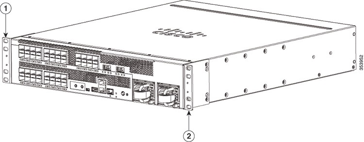
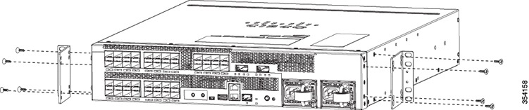
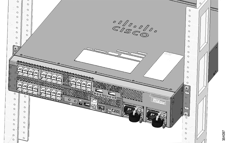
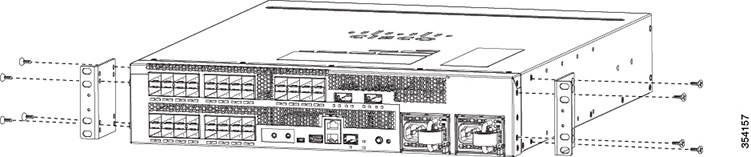
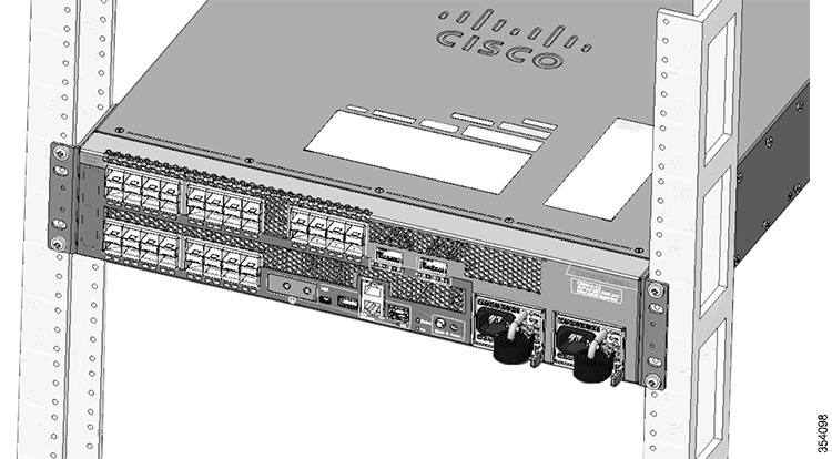
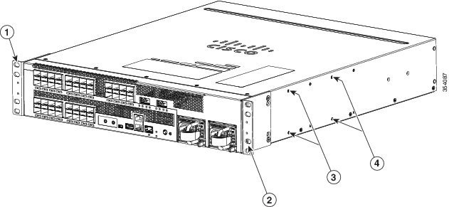
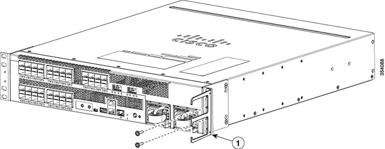
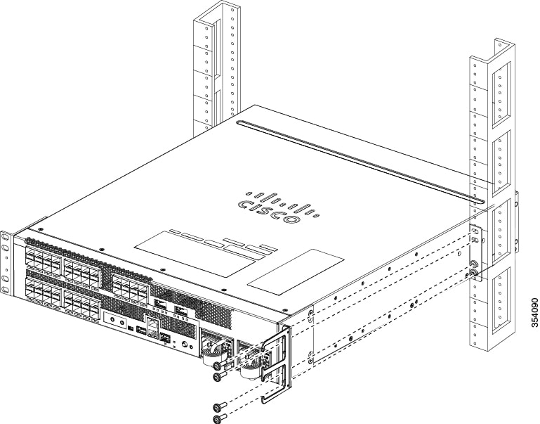
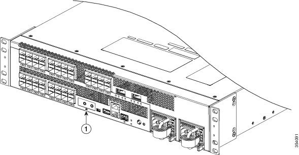
Installing the switch

Install the switch.

Connecting the chassis to system ground

Construct and attach a system ground wire from the building (earth) ground to the system ground point on the chassis.

Installing and cabling the power supply or supplies

Power supplies that are ordered with the switch are installed in the switch. If ordered separately, install the power supplies. Connect the power supplies.

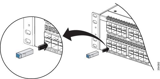
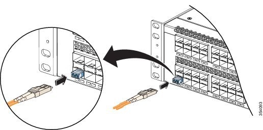
Cabling the chassis and modules to the network

The various ports on the chassis must be connected to the network. This process can involve only attaching a network interface cable to the port or it can include the installation of a transceiver of some type in port and then attaching the network interface cable to the transceiver.

Powering up the chassis

After completing the network cabling and making sure that system ground is connected, the power supplies can be turned on. The system powers up and runs through a set of built-in diagnostics.

Safety Warnings


Warning

Class 1 laser product. Statement 1008

Warning

This unit is intended for installation in restricted access areas. A restricted access area can be accessed only through the use of a special tool, lock and key, or other means of security. Statement 1017

Warning

This unit might have more than one power supply connection. All connections must be removed to de-energize the unit. Statement 1028

Warning

Only trained and qualified personnel should be allowed to install, replace, or service this equipment. Statement 1030

Warning

To prevent personal injury or damage to the chassis, never attempt to lift or tilt the chassis using the handles on modules (such as power supplies, fans, or cards); these types of handles are not designed to support the weight of the unit. Statement 1032

Warning

Hazardous voltage or energy is present on the backplane when the system is operating. Use caution when servicing. Statement 1034

Warning

This product requires short-circuit (overcurrent) protection, to be provided as part of the building installation. Install only in accordance with national and local wiring regulations. Statement 1045

Warning

When installing or replacing the unit, the ground connection must always be made first and disconnected last. Statement 1046

Warning

Installation of the equipment must comply with local and national electrical codes.. Statement 1074

Warning

Invisible laser radiation may be emitted from disconnected fibers or connectors. Do not stare into beams or view directly with optical instruments. Statement 1051

Before starting the installation procedures in this chapter, see the “Site Preparation Checklist” section on page 2-15 to verify that all site planning activities were completed.

Rack-Mounting Guidelines


Note

The switch is designed to be installed in standard 19-inch racks.


Before rack-mounting the switch, ensure that the equipment rack complies with the following guidelines:

  • The width of the rack, measured between the two front-mounting strips or rails, must be one of the following measurements:

    • 17.5 inches (44.45 cm)

    • 17.75 inches (45.09 cm)

  • The depth of the rack, measured between the front- and rear-mounting strips, must be at least 19.25 inches (48.9 cm).

  • The rack must have sufficient vertical clearance to insert the chassis: 8.75 inches (22.23 cm) (5 RU)


Note

Chassis height is sometimes measured in rack units (RU or just U) where 1 RU or 1 U equals 1.75 in (44.45 mm). A typical server rack is 42 RU or 42 U in height.


Caution

If the rack is on wheels, ensure that the brakes are engaged and that the rack is stabilized.

Warning

Stability hazard. The rack stabilizing mechanism must be in place, or the rack must be bolted to the floor before you slide the unit out for servicing. Failure to stabilize the rack can cause the rack to tip over. Statement 1048

Warning

To prevent bodily injury when mounting or servicing this unit in a rack, you must take special precautions to ensure that the system remains stable. The following guidelines are provided to ensure your safety:

  • This unit should be mounted at the bottom of the rack if it is the only unit in the rack.
  • When mounting this unit in a partially filled rack, load the rack from the bottom to the top with the heaviest component at the bottom of the rack.
  • If the rack is provided with stabilizing devices, install the stabilizers before mounting or servicing the unit in the rack. Statement 1006


Note

To maintain proper air circulation through the Catalyst switch chassis, you should maintain a recommended separation of a minimum of 6 inches (15 cm) between a wall and the chassis air intake or a wall and the chassis air exhaust. You should also allow a minimum separation of 12 inches (30.5 cm) between the hot air exhaust on one chassis and the air intake on another chassis. Failure to maintain adequate air space can cause the chassis to overheat and the system to fail.


Unpacking the Switch


Note

Do not discard the shipping container when you unpack the switch. Flatten the shipping cartons and store them with the pallet. You will need these containers if you need to move or ship the switch in the future.


Check the contents of the accessory kit. Verify that you received all listed equipment, which should include the following:

  • Grounding lug and disposable ESD strap.
  • Optional equipment that you ordered, such as console cables, transceivers, or special connectors.

  • Blank covers are installed for the power supply slots on the chassis.

Chassis Installation Kits and Cable Guides

The chassis ships with an accessory kit, which includes chassis installation kits and cable guides:

  • Standard 19-inch rack-mount L brackets (factory-installed on the chassis). Associated rack-mounting hardware is included in the accessory kit.

  • Two cable management guides are included in the accessory kit.

Installing the Switch Chassis

Installation Accessory Kits

The switch chassis is designed to be installed in a standard 19-inch rack, either open or enclosed. The chassis is shipped with the 19-inch rack-mount L brackets that are factory installed on the left-front and right-front of the chassis. Screws are included with the accessory kit that are used to secure the chassis in the rack enclosure.


Note

Depending on the manufacturer, the rack posts might be prethreaded to accept either 10-32 or 12-24 screws. If the rack posts are not prethreaded, you must install 10-32 or 12-24 clip nuts or cage nuts to secure the rack-mount screws. The clip nuts or the cage nuts are not included as part of the accessory kit and must be obtained on your own.


The accessory kit also contains the following:

  • Cable guides— Two cable guides can be installed on the front of the chassis using the same sets of screws that secure the chassis rack-mount brackets to the rack posts.

L Brackets on the Chassis

The switch chassis is shipped with two L brackets installed toward the front of each side of the chassis, as shown in the following figure.

Figure 1. Brackets on the Switch Chassis


1

Left L bracket

2

Right L bracket

Installing the L Brackets in a rack


Note

In many older equipment racks, the rack posts are prethreaded to accept either 10-32 or 12-24 screws. Newer rack enclosure posts might not be prethreaded. These rack enclosure posts require that you install 10-32 or 12-24 clip nuts or cage nuts to secure the rack-mount screws. The clip nuts or the cage nuts are not included as part of the accessory kit and must be obtained on your own.

Before you install the shelf brackets, determine the clearance between the insides of the left and right rails of your rack system:

Installing the L Brackets on a Rack with 17.5 in. (44.45 cm) Opening

Procedure


Step 1

Attach the L bracket to the chassis as shown in the following figure.

Figure 2. Attaching the L Bracket to the chassis


Step 2

Position the chassis in the rack and align the mounting holes in the L bracket with the mounting holes in the equipment rack.

Step 3

Secure the chassis using four screws through the holes in the L bracket and into the rack post holes.

Figure 3. Installing the chassis on a Rack with a 17.5 in. (44.45 cm) Opening


Installing the L Brackets on a Rack with 17.75 in. (45.09 cm) Opening

Procedure


Step 1

Attach the L bracket to the chassis as shown in the following figure.

Figure 4. Attaching the L Bracket to the chassis


Step 2

Position the chassis in the rack and align the mounting holes in the L bracket with the mounting holes in the equipment rack.

Step 3

Secure the chassis using four screws through the holes in the L bracket and into the rack post holes.

Figure 5. Installing the chassis on a Rack with a 17.75 in. (45.09 cm) Opening


Installing the Chassis in a Two-Post Rack


Note

The chassis are designed to be mounted in equipment racks that meet ANSI/EIA 310-D and ETS 300-119 standards.

Procedure


Step 1

Before rack-mounting the chassis, determine if you need to move the L brackets so that the chassis is installed in one of the recommended positions:

  • Positioned so the front of the chassis is approximately flush with the front of the rack:

    • The chassis is shipped with the L brackets in the correct location; there is no need to move them.

  • Positioned so approximately one fourth of the chassis protrudes in front of the rack:

    • Remove the screws in the L brackets.

    • Reposition the L brackets to align with the first set of holes behind the holes where the L brackets were originally installed (see figure below).

    • Secure the brackets with the screws.

  • Positioned so approximately one half of the chassis protrudes in front of the rack:

    • Remove the screws in the L brackets.

    • Reposition the L brackets to align with the second set of holes behind the holes where the L brackets were originally installed (see figure below).

    • Secure the brackets with the screws.

Figure 6. Locations of Screw Holes for Alternate Chassis Installation Positions


1

Left L bracket already attached. When the chassis is installed, the front of the chassis is approximately flush with the front of the rack.

3

Screw holes for reattaching the L brackets. When the chassis is installed, approximately one quarter of it protrudes in front of the rack.

2

Right L bracket already attached. When the chassis is installed, the front of the chassis is approximately flush with the front of the rack.

4

Screw holes for reattaching the L brackets. When the chassis is installed, approximately one half of it protrudes in front of the rack.

Step 2

Rest the back end of the chassis on the rack-mount shelf and carefully slide the chassis into the rack until the L brackets meet the front rails of the rack system.

Step 3

Locate the rack post holes that align with the chassis L bracket holes. If the rack post holes are prethreaded, determine if the threads are 10-32 or 12-24. If the rack post holes are unthreaded, install eight or ten (four or five on each side) either 10-32 or 12-24 clip or cage nuts over the rack post holes to accept the installation screws.

Note 
Clip nuts or cage nuts are not included as part of the accessory kit that comes with the chassis. You must obtain them yourself.
Step 4

If you want to install one or both of the optional cable guide assemblies, position the cable guides so that the cable guide mounting holes are aligned with L bracket holes as shown in figure below.

Figure 7. Installing the Cable Mount Guides


1

Cable guide

Step 5

Install all four M4.0x20mmL screws (two on each side) through the cable guide mounting holes, into the L bracket holes. Tighten the screws securely.

Step 6

Secure the chassis using four screws through the holes in the L bracket and into the rack post holes.

Figure 8. Installing the Cable Mount Guides


1

10-32 or 12-24 screws


What to do next

After installing the chassis in its location, complete the installation process by following these procedures:

Establishing the System Ground

This section describes how to connect a system ground to the switch.


Caution

Installations that rely solely on system grounding using only an AC third-prong ground run a substantially greater risk of equipment problems and data corruption than those installations that use both the AC third-prong ground and a properly installed system ground.

The system ground provides additional grounding for EMI shielding requirements and grounding for the low voltage supplies (DC-DC converters) on the modules. You must observe the following system grounding guidelines for your chassis:

  • You must install the system ground connection with any other rack or system power ground connections that you make. The system ground connection is required if FXS modules are installed or if this equipment is installed in a U.S. or European Central Office.

  • You must connect both the system ground connection and the power supply ground connection to an earth ground. The system ground connection is required if FXS modules are installed or if this equipment is installed in a U.S. or European Central Office.

  • When using DC-input power supplies, you must install the system (ground before you attach the source DC power cables to the DC PEM. Power down the chassis before attaching the system ground.


Note

In all situations, grounding practices must comply with Section 250 of the National Electric Code (NEC) requirements or local laws and regulations. A 8-24 AWG grounding wire is preferred from the chassis to the rack ground or directly to the common bonding network (CBN). The equipment rack should also be connected to the CBN with 8-24 AWG grounding wire.

Note

The system ground serves as the primary safety ground for chassis that are equipped with DC-input power supplies. The DC-input power supplies for these chassis do not have a separate ground.


Required Tools and Equipment

To connect the system ground, you need the following tools and materials:

  • Grounding lug—A two-hole standard barrel lug. Supports up to 8-24 AWG wire. Supplied as part of accessory kit.

  • Grounding screws—Two M4 x 8 mm (metric) pan-head screws. Supplied as part of the accessory kit.

  • Grounding wire—Not supplied as part of accessory kit. The grounding wire should be sized according to local and national installation requirements. Depending on the power supply and system, a 12 AWG to 6 AWG copper conductor is required for U.S. installations. 8-24 AWG wire is recommended. The length of the grounding wire depends on the proximity of the switch to proper grounding facilities.

  • No. 1 Phillips screwdriver.

  • Crimping tool to crimp the grounding wire to the grounding lug.

  • Wire-stripping tool to remove the insulation from the grounding wire.

Connecting the System Ground

To establish an earth ground for the chassis, you must attach a grounding cable from the chassis’ grounding lug to the rack.

Before you begin

Review the following illustration and table.

Figure 9. System Ground Location


1

Location of system ground lug

Procedure


Step 1

Use a wire-stripping tool to remove approximately 0.75 inch (19 mm) of the covering from the end of the grounding wire.

Step 2

Insert the stripped end of the grounding wire into the open end of the grounding lug.

Step 3

Crimp the grounding wire in the barrel of the grounding lug. Verify that the ground wire is securely attached to the ground lug.

Step 4

Place the grounding wire lug against the grounding pad, making sure that there is solid metal-to-metal contact.

Step 5

Secure the grounding lug to the chassis with two M4 screws. Ensure that the grounding lug and the grounding wire will not interfere with other switch hardware or rack equipment.

Step 6

Prepare the other end of the grounding wire with a ring lug, and secure it to the rack with a screw.


Installing the Power Supplies in the Switch Chassis

The chassis power supplies (AC or DC) might be shipped separately from the switch chassis. Remove the power supply from its shipping packaging, and then install and connect it to the site power by referring to Installing Power Supplies.


Note

AC-input and DC-input power supplies can be mixed in a chassis.

Connecting the Switch Console Port

This section describes how to connect to the supervisor engine console port from a terminal or modem. The console port on the supervisor engine allows you to perform the following functions:

  • Configure the switch from the CLI.
  • Monitor network statistics and errors.
  • Configure SNMP agent parameters.
  • Download software updates to the switch, or distribute software images residing in flash memory to attached devices.

The console port is located on the front panel of the chassis.

The accessory kit that shipped with your switch might contain the necessary cable and adapters (depending on if you ordered them) to connect a terminal or modem to the console port. To connect a terminal to the console port using the cable and adapters provided, follow these steps:

Procedure


Step 1

Connect to the port using the RJ-45-to-RJ-45 cable and RJ-45-to-DB-25 DTE adapter or RJ-45-to-DB-9 DTE adapter (labeled "Terminal").

Step 2

Position the cable in the cable guide (if installed). Make sure there are no sharp bends in the cable.

Step 3

Check the terminal documentation to determine the baud rate. The baud rate of the terminal must match the default baud rate (9600 baud) of the console port. Set up the terminal as follows:

  • 9600 baud

  • 8 data bits

  • No parity

  • 1 stop bits


Connecting the Uplink Ports

SFP and SFP+ Transceiver Modules

The SFP and SFP+ transceiver modules provide copper or fiber-optic connections to other devices. These transceiver modules are field-replaceable and provide the uplink interfaces when installed in an SFP module slot. The SFP modules have LC connectors for fiber-optic connections or RJ-45 connectors for copper connections.

For Cisco SFP and SFP+ transceiver modules documentation, including compatibility matrixes, refer to this URL: http://www.cisco.com/en/US/products/hw/modules/ps5455/products_device_support_tables_list.html

Installing SFP and SFP+ Transceiver Modules

Before you begin

For cable specifications, see Appendix B, “Connector and Cable Specifications.”

Observe these precautions:


Warning

Class 1 laser product. Statement 1008
  • Do not remove the dust plugs from the SFP transceiver modules or the rubber caps from the fiber-optic cable until you are ready to connect the cable. The plugs and caps protect the module ports and cables from contamination and ambient light.

  • Removing and installing an SFP transceiver module can shorten its useful life. Do not remove and insert any SFP transceiver module more often than is necessary.

  • To prevent ESD damage, follow your normal board and component handling procedures when connecting cables to the switch and other devices.

Procedure


Step 1

Attach an ESD-preventive wrist strap to your wrist and to an earth ground surface.

Step 2

Find the send (Tx) and receive (Rx) markings that identify the top of the SFP module.

On some SFP transceiver modules, the send and receive (Tx and Rx) markings might be shown by arrows that show the direction of the connection.

Step 3

If the SFP transceiver module has a bale-clasp latch, move it to the open, unlocked position.

Step 4

Align the module in front of the slot opening, and push until you feel the connector snap into place.

Figure 10. Installing an SFP Module in the SFP Transceiver Module Port


Step 5

If the module has a bale-clasp latch, close it to lock the SFP transceiver module in place.

Note 
If you are inserting the SFP transceiver module in the lower ports, you need to invert the module.
Step 6

Remove the SFP dust plugs and save.

Step 7

Connect the SFP cables.

Figure 11. Port with SFP Transceiver Modules Installed


Removing SFP or SFP+ Transceiver Modules

Procedure


Step 1

Attach an ESD-preventive wrist strap to your wrist and to an earth ground surface.

Step 2

Disconnect the cable from the SFP transceiver module. For reattachment, note which cable connector plug is send (Tx) and which is receive (Rx).

Step 3

Insert a dust plug into the optical ports of the SFP transceiver module to keep the optical interfaces clean.

Step 4

If the module has a bale-clasp latch, pull the bale out and down to eject the module. If you cannot use your finger to open the latch, use a small, flat-blade screwdriver or other long, narrow instrument to open it.

Step 5

Grasp the SFP transceiver module, and carefully remove it from the slot.

Step 6

Place the SFP transceiver module in an antistatic bag or other protective environment.


Verifying Switch Chassis Installation

Procedure


Step 1

Ensure that the unused power supply unit has a metal cover plate installed.

Step 2

Turn on the system. During the power-up sequence, the system performs a series of bootup diagnostic tests.

Additional system diagnostic tests are available. These tests allow you to perform a complete sanity check on the system prior to inserting the system into your network and to monitor the health of the system while the system is running. Refer to the “Online Diagnostics” section on page 3-19 for further information.

Tip 
When prestaging systems in a nonproduction environment, we recommend that you run all diagnostic tests, including the disruptive tests, to prescreen the systems for any failures.

Online Diagnostics

The switch running Cisco IOS has many levels of online diagnostic capabilities. The online diagnostics are divided into four categories:

  • Bootup—Bootup diagnostics automatically run during bootup, module OIR, or switchover to a backup supervisor engine.

  • Background health—Monitoring diagnostic tests are continuously run by the system to monitor system health.

  • On-demand online diagnostics—On-demand online diagnostics can be used to run any test from the CLI. You can also run on-demand online diagnostics to perform a sanity check on the system hardware. Some of these tests are disruptive and will impact traffic flow.You must follow the on-demand diagnostic guidelines exactly to avoid false failures.

  • Scheduled diagnostics—Scheduled diagnostics can be used to run any of the above tests at user-designated intervals.

For complete information on the online diagnostic tests and how to run them, refer to the software configuration guide.