Switch Models
|
Switch Model |
Description |
|---|---|
|
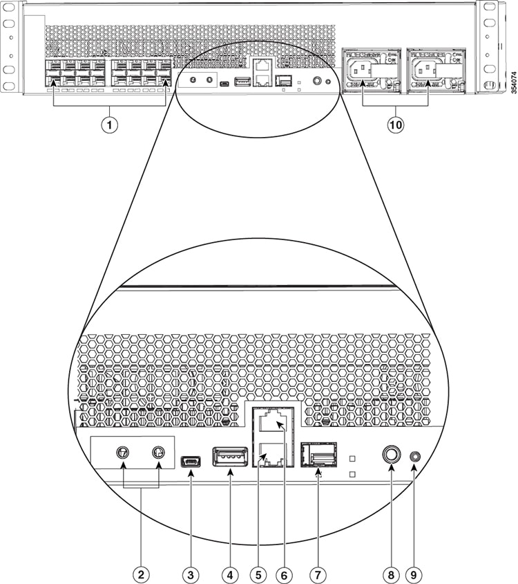
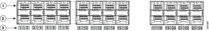
Catalyst 6816-X-LE |
16 10-Gigabit SFP+ ports and two power supply slots |
|
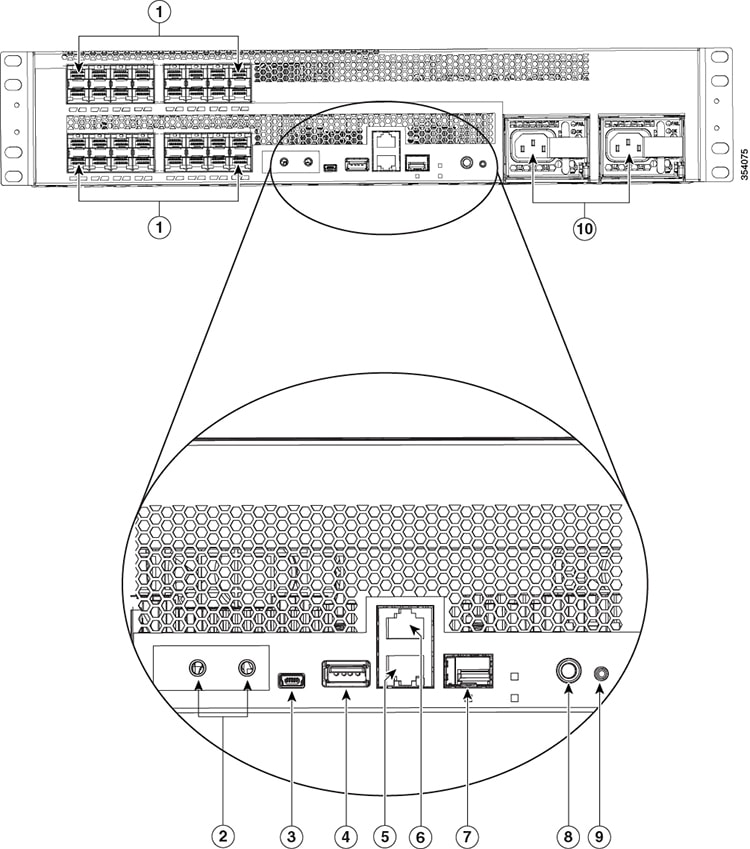
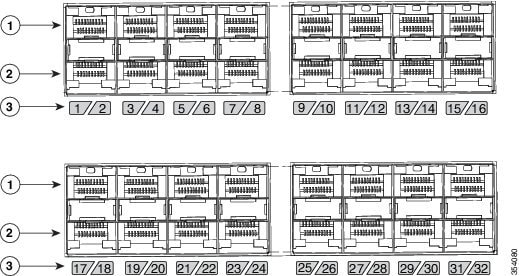
Catalyst 6832-X-LE |
32 10-Gigabit SFP+ ports and two power supply slots |
|
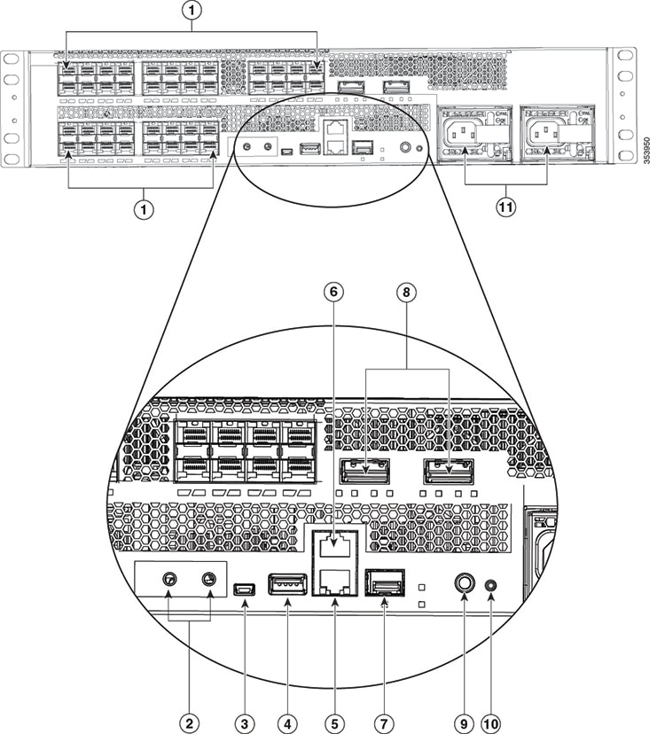
Catalyst 6824-X-LE-40G |
24 10-Gigabit SFP+ports and two 40-Gigabit QSFP+ uplink ports, and two power supply slots |
|
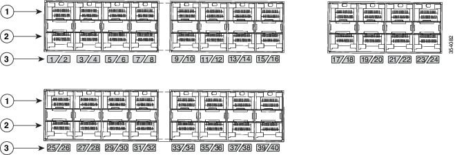
Catalyst 6840-X-LE-40G |
40 10-Gigabit SFP+ and two 40-Gigabit QSFP+ uplink ports, and two power supply slots |

 Feedback