Preparing for Installation
Safety Warnings
This section includes the basic installation caution and warning statements. Read this section before you start the installation procedure. Translations of the warning statements appear in the Regulatory Compliance and Safety Information guide on Cisco.com.
 Warning |
Before working on equipment that is connected to power lines, remove jewelry (including rings, necklaces, and watches). Metal objects will heat up when connected to power and ground and can cause serious burns or weld the metal object to the terminals. Statement 43 |
Warning |
Do not stack the chassis on any other equipment. If the chassis falls, it can cause severe bodily injury and equipment damage. Statement 48 |
Warning |
Ethernet cables must be shielded when used in a central office environment. Statement 171 |
Warning |
Read the wall-mounting instructions carefully before beginning installation. Failure to use the correct hardware or to follow the correct procedures could result in a hazardous situation to people and damage to the system. Statement 378 |
Warning |
Do not work on the system or connect or disconnect cables during periods of lightning activity. Statement 1001 |
Warning |
Read the installation instructions before connecting the system to the power source. Statement 1004 |
Warning |
To prevent bodily injury when mounting or servicing this unit in a rack, you must take special precautions to ensure that the system remains stable. The following guidelines are provided to ensure your safety:
|
Warning |
This product is a Class 1 laser product. |
Warning |
This unit is intended for installation in restricted access areas. Only skilled, instructed, or qualified personnel can access a restricted access area. |
Warning |
The plug-socket combination must be accessible at all times, because it serves as the main disconnecting device. Statement 1019 |
Warning |
Use copper conductors only. Statement 1025 |
Warning |
This unit might have more than one power supply connection. To reduce risk of electric shock, remove all connections to de-energize the unit.  |
Warning |
Only trained and qualified personnel should be allowed to install, replace, or service this equipment. Statement 1030 |
Warning |
Ultimate disposal of this product should be handled according to all national laws and regulations. Statement 1040 |
Warning |
To prevent the system from overheating, do not operate it in an area that exceeds the maximum recommended ambient temperature of: <113°F (45°C). Statement 1047 |
Warning |
This warning symbol means danger. You are in a situation that could cause bodily injury. Before you work on any equipment, be aware of the hazards involved with electrical circuitry and be familiar with standard practices for preventing accidents. Use the statement number provided at the end of each warning to locate its translation in the translated safety warnings that accompanied this device. Statement 1071 |
Warning |
Voltages that present a shock hazard may exist on Power over Ethernet (PoE) circuits if interconnections are made using uninsulated exposed metal contacts, conductors, or terminals. Avoid using such interconnection methods, unless the exposed metal parts are located within a restricted access location and users and service people who are authorized within the restricted access location are made aware of the hazard. A restricted access area can be accessed only through the use of a special tool, lock and key or other means of security. Statement 1072 |
Warning |
There are no serviceable parts inside. To avoid risk of electric shock, do not open. |
Warning |
To reduce risk of electric shock or fire, installation of the equipment must comply with local and national electrical codes. |
Warning |
To prevent airflow restriction, allow clearance around the ventilation openings to be at least: 3 inches (7.6 cm). Statement 1076 |
Warning |
This icon is a hot surface warning. To avoid personal injury, do not touch without proper protection.  |
 Note |
The grounding architecture of this product is DC-isolated (DC-I). |
Installation Guidelines
When determining where to install the switch, verify that these guidelines are met:
-
Clearance to the switch front and rear panel meets these conditions:
-
Front-panel LEDs can be easily read.
-
Access to ports is sufficient for unrestricted cabling.
-
AC power cord can reach from the AC power outlet to the connector on the switch rear panel.
-
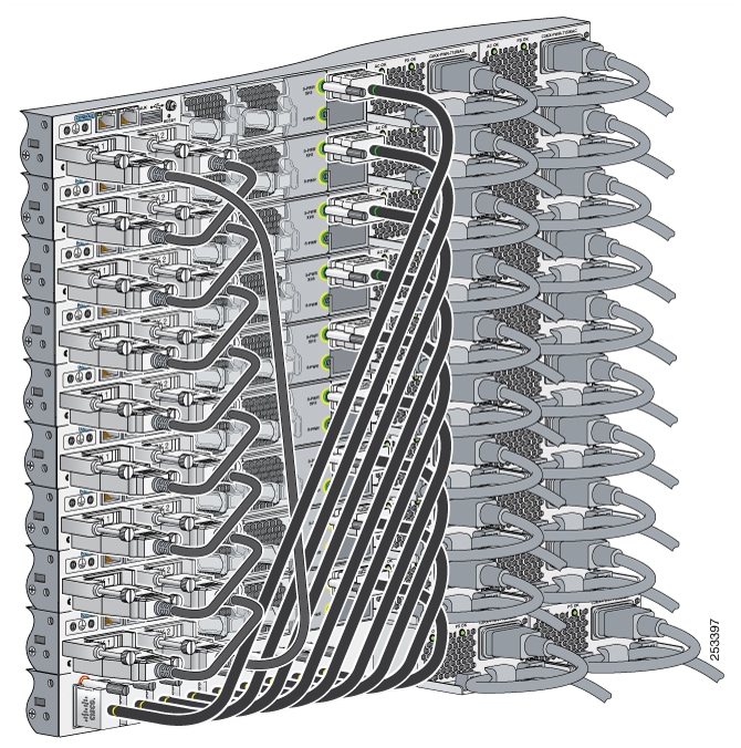
The pluggable transceiver module minimum bend radius and connector length is met. See the Cisco pluggable transceiver module documentation for more information.
-
-
Cabling is away from sources of electrical noise, such as radios, power lines, and fluorescent lighting fixtures. Make sure that the cabling is safely away from other devices that might damage the cables.
-
For switches with the optional 1100 W power supply module, first rack-mount the switch before installing the power-supply module.
-
Make sure power supply modules and fan modules are securely inserted in the chassis before moving the switch.
-
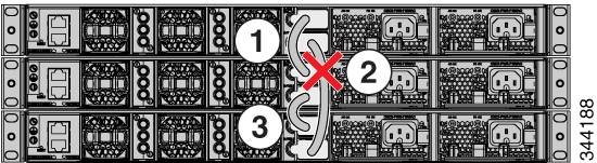
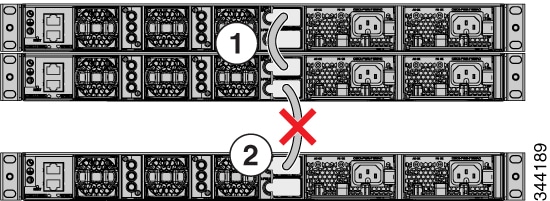
When connecting or disconnecting the power cord on a switch installed with a 350 W or a 715 W power supply that is installed above or below a 1100 W power supply equipped switch, you might need to remove the 1100 W power supply from the switch to access the power cord.
-
Airflow around the switch and through the vents is unrestricted.
-
For copper connections on Ethernet ports, cable lengths from the switch to connected devices can be up to 328 feet (100 meters).
-
Temperature around the unit does not exceed 113°F (45°C). If the switch is installed in a closed or multirack assembly, the temperature around it might be greater than normal room temperature.
-
Humidity around the switch does not exceed 95 percent.
-
Altitude at the installation site is not greater than 10,000 feet.
-
Cooling mechanisms, such as fans and blowers in the switch, can draw dust and other particles causing contaminant buildup inside the chassis, which can result in system malfunction. You must install this equipment in an environment free from dust and foreign conductive or corrosive materials.
Box Contents
The switch getting started guide describes the box contents. If any item is missing or damaged, contact your Cisco representative or reseller for support.
Tools and Equipment
Obtain these necessary tools:
-
A Number-2 Phillips screwdriver.
Verifying Switch Operation
Before you install the switch in a rack, or on a table or shelf, you should power on the switch and verify that the switch passes POST. See the “Running Express Setup” section in the getting started guide for the steps required to connect a PC to the switch and to run Express Setup.
Powering Off the Switch
After a successful POST, disconnect the power cord from the switch. Install the switch in a rack, on a table, or on a shelf as described in Installing the Switch.


 Feedback