- About IPv6
- Licensing Requirements for IPv6
- Prerequisites for IPv6
- Guidelines and Limitations for IPv6
- Configuring IPv6
- Verifying the IPv6 Configuration
- Configuration Examples for IPv6
Configuring IPv6
This chapter describes how to configure Internet Protocol version 6 (IPv6), which includes addressing, on the Cisco NX-OS device.
About IPv6
IPv6, which is designed to replace IPv4, increases the number of network address bits from 32 bits (in IPv4) to 128 bits. IPv6 is based on IPv4 but it includes a much larger address space and other improvements such as a simplified main header and extension headers.
The larger IPv6 address space allows networks to scale and provide global reachability. The simplified IPv6 packet header format handles packets more efficiently. The flexibility of the IPv6 address space reduces the need for private addresses and the use of Network Address Translation (NAT), which translates private (not globally unique) addresses into a limited number of public addresses. IPv6 enables new application protocols that do not require special processing by border routers at the edge of networks.
IPv6 functionality, such as prefix aggregation, simplified network renumbering, and IPv6 site multihoming capabilities, enable more efficient routing. IPv6 supports Routing Information Protocol (RIP), Integrated Intermediate System-to-Intermediate System (IS-IS), Open Shortest Path First (OSPF) for IPv6, and multiprotocol Border Gateway Protocol (BGP).
This section includes the following topics:
- IPv6 Address Formats
- IPv6 Unicast Addresses
- IPv6 Anycast Addresses
- IPv6 Multicast Addresses
- IPv4 Packet Header
- Simplified IPv6 Packet Header
- DNS for IPv6
- Path MTU Discovery for IPv6
- CDP IPv6 Address Support
- LPM Routing Modes
- Virtualization Support
IPv6 Address Formats
An IPv6 address has 128 bits or 16 bytes. The address is divided into eight, 16-bit hexadecimal blocks separated by colons (:) in the format: x:x:x:x:x:x:x:x. Two examples of IPv6 addresses are as follows:
IPv6 addresses contain consecutive zeros within the address. You can use two colons (::) at the beginning, middle, or end of an IPv6 address to replace the consecutive zeros. Table 3-1 shows a list of compressed IPv6 address formats.

Note![]() You can use two colons (::) only once in an IPv6 address to replace the longest string of consecutive zeros within the address.
You can use two colons (::) only once in an IPv6 address to replace the longest string of consecutive zeros within the address.
You can use a double colon as part of the IPv6 address when consecutive 16-bit values are denoted as zero. You can configure multiple IPv6 addresses per interface but only one link-local address.
The hexadecimal letters in IPv6 addresses are not case sensitive.
|
|
|
|
|---|---|---|
A node may use the loopback address listed in Table 3-1 to send an IPv6 packet to itself. The loopback address in IPv6 is the same as the loopback address in IPv4. For more information, see Chapter1, “Overview”
Note![]() You cannot assign the IPv6 loopback address to a physical interface. A packet that contains the IPv6 loopback address as its source or destination address must remain within the node that created the packet. IPv6 routers do not forward packets that have the IPv6 loopback address as their source or destination address.
You cannot assign the IPv6 loopback address to a physical interface. A packet that contains the IPv6 loopback address as its source or destination address must remain within the node that created the packet. IPv6 routers do not forward packets that have the IPv6 loopback address as their source or destination address.
Note![]() You cannot assign an IPv6 unspecified address to an interface. You should not use the unspecified IPv6 addresses as destination addresses in IPv6 packets or the IPv6 routing header.
You cannot assign an IPv6 unspecified address to an interface. You should not use the unspecified IPv6 addresses as destination addresses in IPv6 packets or the IPv6 routing header.
The IPv6-prefix is in the form documented in RFC 2373 where the IPv6 address is specified in hexadecimal using 16-bit values between colons. The prefix length is a decimal value that indicates how many of the high-order contiguous bits of the address comprise the prefix (the network portion of the address). For example, 2001:0DB8:8086:6502::/32 is a valid IPv6 prefix.
IPv6 Unicast Addresses
An IPv6 unicast address is an identifier for a single interface on a single node. A packet that is sent to a unicast address is delivered to the interface identified by that address. This section includes the following topics:
Aggregatable Global Addresses
An aggregatable global address is an IPv6 address from the aggregatable global unicast prefix. The structure of aggregatable global unicast addresses enables strict aggregation of routing prefixes that limits the number of routing table entries in the global routing table. Aggregatable global addresses are used on links that are aggregated upward through organizations and eventually to the Internet service providers (ISPs).
Aggregatable global IPv6 addresses are defined by a global routing prefix, a subnet ID, and an interface ID. Except for addresses that start with binary 000, all global unicast addresses have a 64-bit interface ID. The IPv6 global unicast address allocation uses the range of addresses that start with binary value 001 (2000::/3). Figure 3-1 shows the structure of an aggregatable global address.
Figure 3-1 Aggregatable Global Address Format
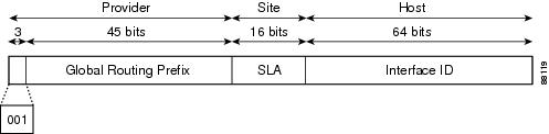
Addresses with a prefix of 2000::/3 (001) through E000::/3 (111) are required to have 64-bit interface identifiers in the extended universal identifier (EUI)-64 format. The Internet Assigned Numbers Authority (IANA) allocates the IPv6 address space in the range of 2000::/16 to regional registries.
The aggregatable global address consists of a 48-bit global routing prefix and a 16-bit subnet ID or Site-Level Aggregator (SLA). In the IPv6 aggregatable global unicast address format document (RFC 2374), the global routing prefix included two other hierarchically structured fields called Top-Level Aggregator (TLA) and Next-Level Aggregator (NLA). The IETF decided to remove the TLS and NLA fields from the RFCs because these fields are policy based. Some existing IPv6 networks deployed before the change might still use networks that are on the older architecture.
A subnet ID, which is a 16-bit subnet field, can be used by individual organizations to create a local addressing hierarchy and to identify subnets. A subnet ID is similar to a subnet in IPv4, except that an organization with an IPv6 subnet ID can support up to 65,535 individual subnets.
An interface ID identifies interfaces on a link. The interface ID is unique to the link. In many cases, an interface ID is the same as or based on the link-layer address of an interface. Interface IDs used in aggregatable global unicast and other IPv6 address types have 64 bits and are in the modified EUI-64 format.
Interface IDs are in the modified EUI-64 format in one of the following ways:
- For all IEEE 802 interface types (for example, Ethernet and Fiber Distributed Data interfaces), the first three octets (24 bits) are the Organizationally Unique Identifier (OUI) of the 48-bit link-layer address (MAC address) of the interface, the fourth and fifth octets (16 bits) are a fixed hexadecimal value of FFFE, and the last three octets (24 bits) are the last three octets of the MAC address. The Universal/Local (U/L) bit, which is the seventh bit of the first octet, has a value of 0 or 1. Zero indicates a locally administered identifier; 1 indicates a globally unique IPv6 interface identifier.
- For all other interface types (for example, serial, loopback, ATM, and Frame Relay types), the interface ID is similar to the interface ID for IEEE 802 interface types; however, the first MAC address from the pool of MAC addresses in the router is used as the identifier (because the interface does not have a MAC address).
Note![]() For interfaces that use the Point-to-Point Protocol (PPP), where the interfaces at both ends of the connection might have the same MAC address, the interface identifiers at both ends of the connection are negotiated (picked randomly and, if necessary, reconstructed) until both identifiers are unique. The first MAC address in the router is used as the identifier for interfaces using PPP.
For interfaces that use the Point-to-Point Protocol (PPP), where the interfaces at both ends of the connection might have the same MAC address, the interface identifiers at both ends of the connection are negotiated (picked randomly and, if necessary, reconstructed) until both identifiers are unique. The first MAC address in the router is used as the identifier for interfaces using PPP.
If no IEEE 802 interface types are in the router, link-local IPv6 addresses are generated on the interfaces in the router in the following sequence:
1.![]() The router is queried for MAC addresses (from the pool of MAC addresses in the router).
The router is queried for MAC addresses (from the pool of MAC addresses in the router).
2.![]() If no MAC addresses are available in the router, the serial number of the router is used to form the link-local addresses.
If no MAC addresses are available in the router, the serial number of the router is used to form the link-local addresses.
3.![]() If the serial number of the router cannot be used to form the link-local addresses, the router uses a Message Digest 5 (MD5) hash to determine the MAC address of the router from the hostname of the router.
If the serial number of the router cannot be used to form the link-local addresses, the router uses a Message Digest 5 (MD5) hash to determine the MAC address of the router from the hostname of the router.
Link-Local Addresses
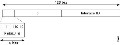
A link-local address is an IPv6 unicast address that can be automatically configured on any interface using the link-local prefix FE80::/10 (1111 1110 10) and the interface identifier in the modified EUI-64 format. Link-local addresses are used in the Neighbor Discovery Protocol (NDP) and the stateless autoconfiguration process. Nodes on a local link can use link-local addresses to communicate; the nodes do not need globally unique addresses to communicate. Figure 3-2 shows the structure of a link-local address.
IPv6 routers cannot forward packets that have link-local source or destination addresses to other links.
Figure 3-2 Link-Local Address Format
IPv4-Compatible IPv6 Addresses
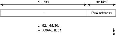
An IPv4-compatible IPv6 address is an IPv6 unicast address that has zeros in the high-order 96 bits of the address and an IPv4 address in the low-order 32 bits of the address. The format of an IPv4-compatible IPv6 address is 0:0:0:0:0:0:A.B.C.D or ::A.B.C.D. The entire 128-bit IPv4-compatible IPv6 address is used as the IPv6 address of a node and the IPv4 address embedded in the low-order 32 bits is used as the IPv4 address of the node. IPv4-compatible IPv6 addresses are assigned to nodes that support both the IPv4 and IPv6 protocol stacks and are used in automatic tunnels. Figure 3-3 shows the structure of an IPv4-compatible IPv6 address and a few acceptable formats for the address.
Figure 3-3 IPv4-Compatible IPv6 Address Format
Unique Local Addresses
A unique local address is an IPv6 unicast address that is globally unique and is intended for local communications. It is not expected to be routable on the global Internet and is routable inside of a limited area, such as a site, and it may be routed between a limited set of sites. Applications may treat unique local addresses like global scoped addresses.
A unique local address has the following characteristics:
- It has a globally unique prefix (it has a high probability of uniqueness).
- It has a well-known prefix to allow for easy filtering at site boundaries.
- It allows sites to be combined or privately interconnected without creating any address conflicts or requiring renumbering of interfaces that use these prefixes.
- It is ISP-independent and can be used for communications inside of a site without having any permanent or intermittent Internet connectivity.
- If it is accidentally leaked outside of a site through routing or the Domain Name Server (DNS), there is no conflict with any other addresses.
Figure 3-4 shows the structure of a unique local address.
Figure 3-4 Unique Local Address Structure

Site-Local Address
Because RFC 3879 deprecates the use of site-local addresses, you should follow the recommendations of unique local addressing (ULA) in RFC 4193 when you configure private IPv6 addresses.
IPv6 Anycast Addresses
An anycast address is an address that is assigned to a set of interfaces that belong to different nodes. A packet sent to an anycast address is delivered to the closest interface—as defined by the routing protocols in use—identified by the anycast address. Anycast addresses are syntactically indistinguishable from unicast addresses because anycast addresses are allocated from the unicast address space. Assigning a unicast address to more than one interface turns a unicast address into an anycast address. You must configure the nodes to which the anycast address to recognize that the address is an anycast address.
Note![]() Anycast addresses can be used only by a router, not a host. Anycast addresses cannot be used as the source address of an IPv6 packet.
Anycast addresses can be used only by a router, not a host. Anycast addresses cannot be used as the source address of an IPv6 packet.
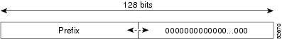
Figure 3-5 shows the format of the subnet router anycast address; the address has a prefix concatenated by a series of zeros (the interface ID). The subnet router anycast address can be used to reach a router on the link that is identified by the prefix in the subnet router anycast address.
Figure 3-5 Subnet Router Anycast Address Format
IPv6 Multicast Addresses
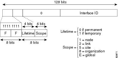
An IPv6 multicast address is an IPv6 address that has a prefix of FF00::/8 (1111 1111). An IPv6 multicast address is an identifier for a set of interfaces that belong to different nodes. A packet sent to a multicast address is delivered to all interfaces identified by the multicast address. The second octet following the prefix defines the lifetime and scope of the multicast address. A permanent multicast address has a lifetime parameter equal to 0; a temporary multicast address has a lifetime parameter equal to 1. A multicast address that has the scope of a node, link, site, or organization, or a global scope, has a scope parameter of 1, 2, 5, 8, or E, respectively. For example, a multicast address with the prefix FF02::/16 is a permanent multicast address with a link scope. Figure 3-6 shows the format of the IPv6 multicast address.
Figure 3-6 IPv6 Multicast Address Format
IPv6 nodes (hosts and routers) are required to join (where received packets are destined for) the following multicast groups:
- All-nodes multicast group FF02:0:0:0:0:0:0:1 (the scope is link-local)
- Solicited-node multicast group FF02:0:0:0:0:1:FF00:0000/104 for each of its assigned unicast and anycast addresses
IPv6 routers must also join the all-routers multicast group FF02:0:0:0:0:0:0:2 (the scope is link-local).
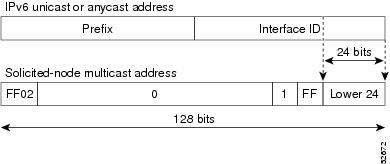
The solicited-node multicast address is a multicast group that corresponds to an IPv6 unicast or anycast address. IPv6 nodes must join the associated solicited-node multicast group for every unicast and anycast address to which it is assigned. The IPv6 solicited-node multicast address has the prefix FF02:0:0:0:0:1:FF00:0000/104 concatenated with the 24 low-order bits of a corresponding IPv6 unicast or anycast address (see Figure 3-7). For example, the solicited-node multicast address that corresponds to the IPv6 address 2037::01:800:200E:8C6C is FF02::1:FF0E:8C6C. Solicited-node addresses are used in neighbor solicitation messages.
Figure 3-7 IPv6 Solicited-Node Multicast Address Format
Note![]() IPv6 has no broadcast addresses. IPv6 multicast addresses are used instead of broadcast addresses.
IPv6 has no broadcast addresses. IPv6 multicast addresses are used instead of broadcast addresses.
IPv4 Packet Header
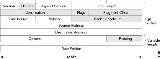
The base IPv4 packet header has 12 fields with a total size of 20 octets (160 bits) (see Figure 3-8). The 12 fields may be followed by an Options field, which is followed by a data portion that is usually the transport-layer packet. The variable length of the Options field adds to the total size of the IPv4 packet header. The shaded fields of the IPv4 packet header are not included in the IPv6 packet header.
Figure 3-8 IPv4 Packet Header Format
Simplified IPv6 Packet Header
The base IPv6 packet header has 8 fields with a total size of 40 octets (320 bits) (see Figure 3-9). Fragmentation is handled by the source of a packet and checksums at the data link layer and transport layer are used. The User Datagram Protocol (UDP) checksum checks the integrity of the inner packet and the base IPv6 packet header and Options field are aligned to 64 bits, which can facilitate the processing of IPv6 packets.
Table 3-2 lists the fields in the base IPv6 packet header.
|
|
|
|---|---|
Similar to the Version field in the IPv4 packet header, except that the field lists number 6 for IPv6 instead of number 4 for IPv4. |
|
Similar to the Type of Service field in the IPv4 packet header. The Traffic Class field tags packets with a traffic class that is used in differentiated services. |
|
New field in the IPv6 packet header. The Flow Label field tags packets with a specific flow that differentiates the packets at the network layer. |
|
Similar to the Total Length field in the IPv4 packet header. The Payload Length field indicates the total length of the data portion of the packet. |
|
Similar to the Protocol field in the IPv4 packet header. The value of the Next Header field determines the type of information that follows the base IPv6 header. The type of information that follows the base IPv6 header can be a transport-layer packet, for example, a TCP or UDP packet, or an Extension Header, as shown in Figure 3-9. |
|
Similar to the Time to Live field in the IPv4 packet header. The value of the Hop Limit field specifies the maximum number of routers that an IPv6 packet can pass through before the packet is considered invalid. Each router decrements the value by one. Because no checksum is in the IPv6 header, the router can decrement the value without needing to recalculate the checksum, which saves processing resources. |
|
Similar to the Source Address field in the IPv4 packet header, except that the field contains a 128-bit source address for IPv6 instead of a 32-bit source address for IPv4. |
|
Similar to the Destination Address field in the IPv4 packet header, except that the field contains a 128-bit destination address for IPv6 instead of a 32-bit destination address for IPv4. |
Figure 3-9 IPv6 Packet Header Format

Optional extension headers and the data portion of the packet are after the eight fields of the base IPv6 packet header. If present, each extension header is aligned to 64 bits. There is no fixed number of extension headers in an IPv6 packet. Each extension header is identified by the Next Header field of the previous header. Typically, the final extension header has a Next Header field of a transport-layer protocol, such as TCP or UDP. Figure 3-10 shows the IPv6 extension header format.
Figure 3-10 IPv6 Extension Header Format
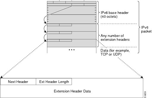
Table 3-3 lists the extension header types and their Next Header field values.
DNS for IPv6
IPv6 supports DNS record types that are supported in the DNS name-to-address and address-to-name lookup processes. The DNS record types support IPv6 addresses (see Table 3-4 ).
Note![]() IPv6 also supports the reverse mapping of IPv6 addresses to DNS names.
IPv6 also supports the reverse mapping of IPv6 addresses to DNS names.
Path MTU Discovery for IPv6
As in IPv4, you can use path MTU discovery in IPv6 to allow a host to dynamically discover and adjust to differences in the MTU size of every link along a data path. In IPv6, however, fragmentation is handled by the source of a packet when the path MTU of one link along a given data path is not large enough to accommodate the size of the packets. Having IPv6 hosts handle packet fragmentation saves IPv6 router processing resources and helps IPv6 networks run more efficiently. Once the path MTU is reduced by the arrival of an ICMP Too Big message, Cisco NX-OS retains the lower value. The connection does not increase the segment size to gauge the throughput.
Note![]() In IPv6, the minimum link MTU is 1280 octets. We recommend that you use an MTU value of 1500 octets for IPv6 links.
In IPv6, the minimum link MTU is 1280 octets. We recommend that you use an MTU value of 1500 octets for IPv6 links.
CDP IPv6 Address Support
You can use the Cisco Discovery Protocol (CDP) IPv6 address support for the neighbor information feature to transfer IPv6 addressing information between two Cisco devices. Cisco Discovery Protocol support for IPv6 addresses provides IPv6 information to network management products and troubleshooting tools.
LPM Routing Modes
By default, Cisco NX-OS programs routes in a hierarchical fashion to allow for the longest prefix match (LPM) on the device. However, you can configure the device for different routing modes to support significantly more LPM route entries.
The following tables list the LPM routing modes that are supported on the Cisco Nexus 9300 Series and 9500 Series switches.
|
|
|
|
|---|---|---|
|
|
|
|
|---|---|---|
3 (for line cards); |
||
For detailed configuration information, see the “Configuring IPv6” section.
Virtualization Support
IPv6 supports virtual routing and forwarding (VRF) instances.
Licensing Requirements for IPv6
The following table shows the licensing requirements for this feature:
Prerequisites for IPv6
Guidelines and Limitations for IPv6
IPv6 has the following configuration guidelines and limitations:
- IPv6 packets are transparent to Layer 2 LAN switches because the switches do not examine Layer 3 packet information before forwarding IPv6 frames. IPv6 hosts can be directly attached to Layer 2 LAN switches.
- You can configure multiple IPv6 global addresses within the same prefix on an interface. However, multiple IPv6 link-local addresses on an interface are not supported.
- Because RFC 3879 deprecates the use of site-local addresses, you should configure private IPv6 addresses according to the recommendations of unique local addressing (ULA) in RFC 4193.
Configuring IPv6
This section includes the following topics:
- Configuring IPv6 Addressing
- Configuring Max-Host Routing Mode (Cisco Nexus 9500 Series Switches Only)
- Configuring Nonhierarchical Routing Mode (Cisco Nexus 9500 Series Switches Only)
- Configuring 64-Bit ALPM Routing Mode (Cisco Nexus 9500 Series Switches Only)
Note![]() If you are familiar with the Cisco IOS CLI, be aware that the Cisco NX-OS commands for this feature might differ from the Cisco IOS commands that you would use.
If you are familiar with the Cisco IOS CLI, be aware that the Cisco NX-OS commands for this feature might differ from the Cisco IOS commands that you would use.
Configuring IPv6 Addressing
You must configure an IPv6 address on an interface so that the interface can forward IPv6 traffic. When you configure a global IPv6 address on an interface, it automatically configures a link-local address and activates IPv6 for that interface.
SUMMARY STEPS
3.![]() ipv6 address { addr [ eui64 ] [ route-preference preference ] [ secondary ] tag tag-id ] ]
ipv6 address { addr [ eui64 ] [ route-preference preference ] [ secondary ] tag tag-id ] ]
ipv6 address ipv6-address use-link-local-only
DETAILED STEPS
This example shows how to configure an IPv6 address:
This example shows how to display an IPv6 interface:
Configuring Max-Host Routing Mode (Cisco Nexus 9500 Series Switches Only)
By default, the device programs routes in a hierarchical fashion (with fabric modules configured to be in mode 4 and line card modules configured to be in mode 3), which allows for longest prefix match (LPM) and host scale on the device.
You can modify the default LPM and host scale to program more hosts in the system, as might be required when the node is positioned as a Layer-2 to Layer-3 boundary node.
Note![]() If you want to further scale the entries in the LPM table, see the “Configuring Nonhierarchical Routing Mode (Cisco Nexus 9500 Series Switches Only)” section to configure the device to program all of the Layer 3 IPv4 and IPv6 routes on the line cards and none of the routes on the fabric modules.
If you want to further scale the entries in the LPM table, see the “Configuring Nonhierarchical Routing Mode (Cisco Nexus 9500 Series Switches Only)” section to configure the device to program all of the Layer 3 IPv4 and IPv6 routes on the line cards and none of the routes on the fabric modules.
Note![]() This configuration impacts both the IPv4 and IPv6 address families.
This configuration impacts both the IPv4 and IPv6 address families.
Note![]() For the max-host routing mode scale numbers, see the Cisco Nexus 9000 Series NX-OS Verified Scalability Guide.
For the max-host routing mode scale numbers, see the Cisco Nexus 9000 Series NX-OS Verified Scalability Guide.
SUMMARY STEPS
2.![]() [no] system routing max-mode host
[no] system routing max-mode host
3.![]() (Optional) show forwarding route summary
(Optional) show forwarding route summary
DETAILED STEPS
|
|
|
|
|---|---|---|
Puts the line cards in Broadcom T2 mode 2 and the fabric modules in Broadcom T2 mode 3 to increase the number of supported hosts. |
||
Configuring Nonhierarchical Routing Mode (Cisco Nexus 9500 Series Switches Only)
If the host scale is small (as in a pure Layer 3 deployment), we recommend programming the longest prefix match (LPM) routes in the line cards to improve convergence performance. Doing so programs routes and hosts in the line cards and does not program any routes in the fabric modules.
Note![]() This configuration impacts both the IPv4 and IPv6 address families.
This configuration impacts both the IPv4 and IPv6 address families.
SUMMARY STEPS
2.![]() [no] system routing non-hierarchical-routing [max-l3-mode]
[no] system routing non-hierarchical-routing [max-l3-mode]
3.![]() (Optional) show forwarding route summary
(Optional) show forwarding route summary
DETAILED STEPS
Configuring 64-Bit ALPM Routing Mode (Cisco Nexus 9500 Series Switches Only)
You can use the 64-bit algorithmic longest prefix match (ALPM) feature to manage IPv4 and IPv6 route table entries. In 64-bit ALPM routing mode, the device can store significantly more route entries. Using this mode, you can program one of the following:
- 80,000 IPv6 entries and no IPv4 entries
- No IPv6 entries and 128,000 IPv4 entries
- x IPv6 entries and y IPv4 entries, where 2 x + y <= 128,000
Note![]() This configuration impacts both the IPv4 and IPv6 address families.
This configuration impacts both the IPv4 and IPv6 address families.
Note![]() For the 64-bit ALPM routing mode scale numbers, see the Cisco Nexus 9000 Series NX-OS Verified Scalability Guide.
For the 64-bit ALPM routing mode scale numbers, see the Cisco Nexus 9000 Series NX-OS Verified Scalability Guide.
SUMMARY STEPS
2.![]() [no] system routing mode hierarchical 64b-alpm
[no] system routing mode hierarchical 64b-alpm
3.![]() (Optional) show forwarding route summary
(Optional) show forwarding route summary
DETAILED STEPS
Verifying the IPv6 Configuration
To display the IPv6 configuration, perform one of the following tasks:
|
|
|
|---|---|
Configuration Examples for IPv6
This example shows how to configure IPv6:
 Feedback