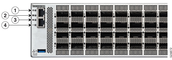
LEDs

Switch Chassis LEDs

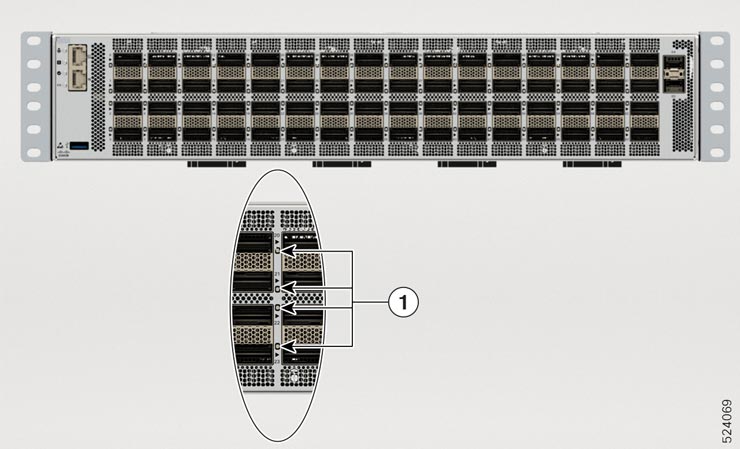
The BCN, STS, and ENV, LEDs are located on the left side of the front of the switch. The port LEDs appear as triangles pointing up or down to the nearest port.

LED

Color

Status

BCN

Flashing blue

The operator has activated this LED to identify this switch in the chassis.

Off

This switch is not being identified.

STS

Green

The switch is operational.

Flashing amber

The switch is booting up.

Amber

Temperature exceeds the minor alarm threshold.

Red

Temperature exceeds the major alarm threshold.

Off

The switch is not receiving power.

(port)

Green

Port admin state is 'Enabled', SFP is present and the interface is connected (that is, cabled, and the link is up).

Amber

Port admin state is 'Disabled, or the SFP is absent, or both.

Off

Port admin state is 'Enabled' and SFP is present, but interface is not connected.

(GPS)

Green

GPS interface provisioned and ports are turned on. ToD, 1PPS, 10MHz are all valid.

Off

Either the interface is not provisioned, or the ports are not turned on. ToD, 1PPS, 10MHz are not valid.

Chassis LEDs

Attention, Status, Synchronization, and GPS LEDs are located both at the far left of the front of the chassis and also on the back of the chassis.

Figure 1. Chassis LEDs - Front View of Cisco Nexus N9364E-SG2-Q

1

Attention

2

Status

3

Activity

4

Link


Note


When only one PSU is connected and active, the Status LED color is amber. When 2 PSUs connected and active, Status LED color is green.


Table 1. Management Port LED

Link

Activity

Description

OFF

Yellow

1000 Mbps link with no activity

OFF

Flashing yellow

1000 Mbps link with activity

Green

Yellow

100 Mbps link with no activity

Flashing green

Flashing yellow

100 Mbps link with activity

Green

OFF

10 Mbps link with no activity

Flashing green

OFF

10 Mbps link with activity

OFF

OFF

No link

Uplink Module LEDs

Each port has an LED. This content describes the LED port status.

Figure 2. Port Status LED for Cisco Nexus 9364E-SG2-Q Chassis

1

Port Status LED

Table 2. Port Status LEDs (one per port)

LED Color

Description

OFF

The port admin state is enabled, SFP is present, but the interface is not up

Amber

The port admin state is disabled, SFP is absent, or both

Green

The port admin state is enabled and the link is up

Fan Module LEDs

LED Color Status

Status

Green

The fan module is operational.

Red

The fan module is not operational (fan is probably not functional).

Off

Fan module is not receiving power.

Table 3. Fan LED

Fan LED

Color

Status Description

Status

OFF

Fan tray is not receiving power

Amber

The fan is inserted into the system and pending to come on-line

Green

Fans are operating normally

Flashing Amber

This fan tray has failed

Power Supply LEDs

The power supply LEDs are located on the right portion of the power supply. Combinations of states indicated by the OK and Fault LEDs signify the status for the module as shown in this table.

Color

Status

Off

Power supply is not receiving power.

Green

Power Supply ON and power being delivered to system.

Flashing green

Power supply is connected to AC power source but not outputting power to the system.

Amber

Power supply failure—possibly one of these conditions:

  • Over voltage

  • Over current

  • Over temperature

  • Fan failure

Flashing amber

Power supply is operating but a warning condition has occurred—possibly one of these conditions:

  • High temperature

  • High power

  • Slow fan