Overview
The Cisco Nexus 9336C-SE1 switch (N9336C-SE1) is a 1-rack mount unit (RU), top of rack (TOR) fixed-port switch designed for deployment in data centers.
To determine which transceivers, adapters, and cables this switch supports, see the Cisco Transceiver Modules Compatibility Information document.
This switch has these ports:
-
36 40/100G QSFP28 ports
-
Two management ports (one 10/100/1000BASE-T port and one SFP port)
-
One console port (RS-232)
-
One USB port
This switch includes these user-replaceable components:
-
Fan modules (6) with these airflow choices:
-
Port-side exhaust fan module with blue coloring (NXA-SFAN-35CFM-PE)
-
Port-side intake fan module with burgundy coloring (NXA-SFAN-35CFM-PI)
Both front-to-back and back-to-front airflow is supported.

Note
To enable or disable displaying the serial number of the NXA-SFAN-35CFM-PI or NXA-SFAN-35CFM-PE fan, enter the [no] hardware fan-sprom command.
Note
Each fan module has two rotors. The switch can function normally if one rotor inside any one fan module fails. In case of more than one rotor failure, the switch issues a warning and powers down in 2 minutes unless the fan module is replaced.
-
-
Power supply modules (two—One for operations and one for redundancy [1+1]) with these choices:
-
750-W port-side exhaust AC power supply with blue coloring (NXA-PAC-750W-PE)
-
750-W port-side intake AC power supply with burgundy coloring (NXA-PAC-750W-PI)
-
1100-W port-side exhaust AC power supply with blue coloring (NXA-PAC-1100W-PE2)
-
1100-W port-side intake AC power supply with burgundy coloring (NXA-PAC-1100W-PI2)
-
1100-W port-side exhaust DC power supply with blue coloring (NXA-PDC-1100W-PE)
-
1100-W port-side intake DC power supply with burgundy coloring (NXA-PDC-1100W-PI)
-
1100-W port-side exhaust HV power supply with blue coloring (NXA-PHV-1100W-PE)
-
1100-W port-side intake HV power supply with burgundy coloring (NXA-PHV-1100W-PI)
Note
All fan modules and power supplies must use the same airflow direction. Dual direction airflow is supported.
-
This figure shows the switch features on the port side of the chassis. 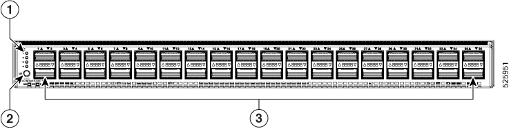
|
1 |
LEDs |
3 |
36 40/100-Gigabit QSFP28 ports |
|
2 |
Lane select button |
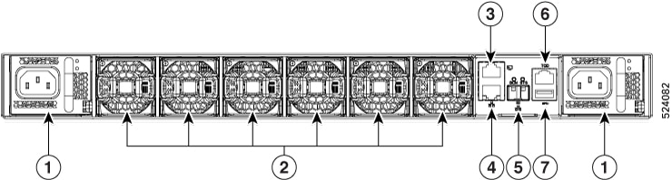
This figure shows the switch features on the power supply side of the chassis.
|
1 |
Power supply modules (1 or 2) (AC power supplies shown) with slots numbered 1 (left) and 2 (right) |
4 |
Management port (Copper RJ45) |
7 |
USB port |
|
2 |
Fan modules (6) with slots numbered from 1 (left) to 6 (right) |
5 |
Management Ethernet port |
||
|
3 |
Console port |
6 |
Time of Day port |
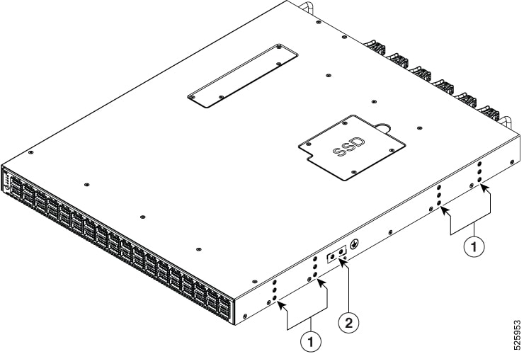
This figure shows the side of the chassis.
|
1 |
Screw holes for mounting brackets |
2 |
Grounding pad |
Depending on whether you plan to position the ports in a hot or cold aisle, you can order the fan and power supply modules with port-side intake or port-side exhaust airflow. For port-side intake airflow, the fan and power supplies have burgundy coloring. For port-side exhaust airflow, the fan and power supplies have blue coloring.
The fan and power supply modules are field replaceable. You can replace one fan module or one power supply module during operations, as long as the other modules are installed and operating. If you have only one power supply installed, you can install the replacement power supply in the open slot before removing the original power supply.
Note |
All fan and power supply modules must have the same direction of airflow. Otherwise, the switch can overheat and shut down. |
 Caution |
If the switch has port-side intake airflow (burgundy coloring for fan modules), locate the ports in the cold aisle. If the switch has port-side exhaust airflow (blue coloring for fan modules), locate the ports in the hot aisle. If you locate the air intake in a hot aisle, the switch can overheat and shut down. |
 Feedback