Cisco Nexus 7000 Series Virtual Device Context Configuration Guide 8.x
Bias-Free Language
The documentation set for this product strives to use bias-free language. For the purposes of this documentation set, bias-free is defined as language that does not imply discrimination based on age, disability, gender, racial identity, ethnic identity, sexual orientation, socioeconomic status, and intersectionality. Exceptions may be present in the documentation due to language that is hardcoded in the user interfaces of the product software, language used based on RFP documentation, or language that is used by a referenced third-party product. Learn more about how Cisco is using Inclusive Language.
This chapter describes how to manage virtual device contexts (VDCs) on Cisco NX-OS devices.
Finding Feature
Information
Your software release might not support all the features documented in this module. For the latest caveats and feature information,
see the Bug Search Tool at https://bst.cloudapps.cisco.com/bugsearch and the release notes for your software release. To find information about the features documented in this module, and to
see a list of the releases in which each feature is supported, see the "New and Changed Information"chapter or the Feature
History table in this chapter.
Information About
Managing VDCs
After you create a
VDC, you can change the interface allocation, VDC resource limits, and the
single-supervisor and dual-supervisor high availability (HA) policies. You can
also save the running configuration of all VDCs on the physical device to the
startup configuration.
Note
Ports on F3 modules may increment L1 and/or L2 errors (symbol errors, FCS errors, CRC errors, and so on) in the following
instances:
a) Link goes up and then down (errors will increment during link down and link up; errors will stop incrementing if the link
is fully up)
b) Link is down but optics and cable are still plugged in.
Workaround: Administratively shut down any unused ports.
In case, any of these errors are incrementing during traffic transmission, there may be genuine issue with optics and/or cable
or F3 hardware and these cases need to be investigated by Cisco TAC.
The following VDC type support is available in Cisco NX-OS Release 7.3(0)DX(1) and Cisco NX-OS Release 7.3(1)D1(1):
VDC Type
Layer 2
Layer 3
Fabric Path
VxLAN
FEX
MPLS
OTV
LISP
GTP
L2 Gateways
Table Sizes
M3
Yes
Yes
No
Yes
No
Yes
Yes
Yes
Yes
Yes
M3 size
F3+M3
Yes
Yes
No
Yes
No
Yes
Yes
Yes
No
No
F3 size
Starting from Cisco NX-OS Release 8.0(1), the following VDC type support is available:
VDC Type
Layer 2
Layer 3
Fabric Path
VxLAN
FEX
MPLS
OTV
LISP
GTP
L2 Gateways
Table Sizes
M2+M3
Yes
Yes
No
Yes
No
Yes
Yes
Yes
No
No
M2
Starting from Cisco NX-OS Release 8.3(1), the following VDC type support is available:
See the Cisco NX-OS FCoE Configuration Guide for Cisco Nexus 7000 and Cisco MDS 9500 Guide for information on allocating interfaces for storage VDCs and FCoE.
When you create a VDC, you can allocate I/O interfaces to the VDC. Later, the deployment of your physical device might change,
and you can reallocate the interfaces as necessary.
Note
Beginning with Cisco NX-OS Release 5.2(1) for Nexus 7000 Series devices, all members of a port group are automatically allocated
to the VDC when you allocate an interface.
The following Cisco Nexus 7000 Series Ethernet modules have the following number of port groups and interfaces:
N7K-F132XP-15 (2 interfaces x 16 port groups = 32 interfaces)—There are no restrictions on the interface allocation between
VDCs, but we recommend that interfaces that belong to the same port group be in a single VDC.
N7K-F248XP-25, N7K-F248XP-25E, N7K-F248XT-25E, N77-F248XP-23E (4 interfaces x 12 port groups = 48 interfaces)—There are no
restrictions on the interface allocation between VDCs, but we recommend that interfaces that belong to the same port group
be in a single VDC.
N77-F248XP-23E (4 interfaces x 12 port groups = 48 interfaces)—There are no restrictions on the interface allocation between
VDCs, but we recommend that interfaces that belong to the same port group be in a single VDC.
N7K-F306CK-25—Has six ASICs, 6 port groups of 1x100G ASIC.
N7K-F312FQ-25—Has six ASICs, 6 port groups of 2x40G ASIC.
N7K-F348XP-25—Has six ASICs, 6 port groups of 8x10G ASIC.
N77-F312CK-26—Has twelve ASICs, 12 port groups of 1x100G ASIC.
N77-F324FQ-25—Has twelve ASICs, 12 port groups of 2x40G ASIC.
N77-F348XP-23—Has six ASICs, 6 port groups of 8x10G ASIC.
N7K-M108X2-12L (1 interface x 8 port groups = 8 interfaces)—There are no restrictions on the interface allocation between
VDCs.
N7K-M132XP-12 (4 interfaces x 8 port groups = 32 interfaces) and N7K-M132XP-12L (same as non-L M132) (1 interface x 8 port
groups = 8 interfaces)—All M132 cards require allocation in groups of 4 ports and you can configure 8 port groups. Interfaces
belonging to the same port group must belong to the same VDC.
N7K-M148GS-11 (12 interfaces x 4 port groups = 48 interfaces), N7K-M148GS-11L, N7K-M148GT-11, N7K-M148GT-11L (same as non-L
M148) (1interface x 48 port groups = 48 interfaces) —There are no restrictions on the interface allocation between VDCs, but
we recommend that interfaces that belong to the same port group be in a single VDC.
N7K-M202CF-22L (1 interface x 2 port groups = 2 interfaces)—There are no restrictions on the interface allocation between
VDCs.
N7K-M206FQ-23L (1 interface x 6 port groups = 6 interfaces)—There are no restrictions on the interface allocation between
VDCs.
N7K-M224XP-23L (1 interface x 24 port groups = 24 interfaces)—There are no restrictions on the interface allocation between
VDCs.
N7K-M324FQ-25L—Has four ASICs, 4 port groups of 6x40G ASIC.
N7K-M348XP-25L—Has two ASICs, 2 port groups of 24x10G ASIC.
N77-F430CQ-36 (30 port 100G Ethernet Module)
The Cisco Nexus 7700 Series M3 Ethernet modules have the following number of port groups and interfaces. VDC allocation is
based on port group boundaries.
N77-M312CQ-26L—Has six ASICs, 6 port groups of 2x100G ASIC
N77-M324FQ-25L—Has four ASICs, 4 port groups of 6x40G ASIC.
N77-M348XP-23L—Has two ASICs, 2 port groups of 24x10G ASIC.
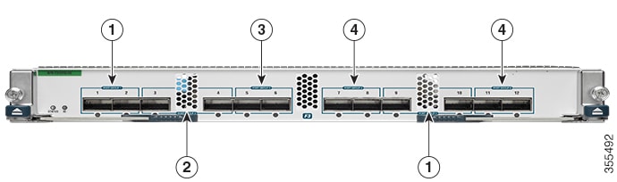
On the Cisco Nexus 7000 Series 32-port, 10-Gbps Ethernet module N7K-F132XP-15, you must allocate the interfaces on your physical
device in the specified combination. This module has 16 port groups that consist of 2 ports each (2 interfaces x 16 port groups
= 32 interfaces). Interfaces that belong to the same port group must belong to the same VDC.
Note
You can configure the limit-resource module-type command only from the VDC configuration mode and not from a VDC resource
template.
Figure 1. Example Interface Allocation for Port Groups on a Cisco 7000 Series 10-Gbps Ethernet Module (N7K-F132XP-15)
The callouts in the figure above represent an example of VDC allocation. The table below shows the VDC that each callout represents.
Table 1. Example VDC Allocation
VDC
Callout
VDC A
1
VDC B
2
VDC C
3
VDC D
4
The table below shows the port numbering for the port groups.
Table 2. Port Numbers for Port Groups on the Cisco Nexus 7000 Series 10-Gbps Ethernet Module N7K-F132XP-15
Port Group
Port Numbers
Group 1
1 and 2
Group 2
3 and 4
Group 3
5 and 6
Group 4
7 and 8
Group 5
9 and 10
Group 6
11 and 12
Group 7
13 and 14
Group 8
15 and 16
Group 9
17 and 18
Group 10
19 and 20
Group 11
21 and 22
Group 12
23 and 24
Group 13
25 and 26
Group 14
27 and 28
Group 15
29 and 30
Group 16
31 and 32
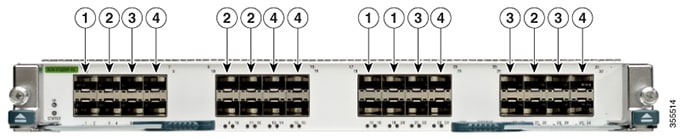
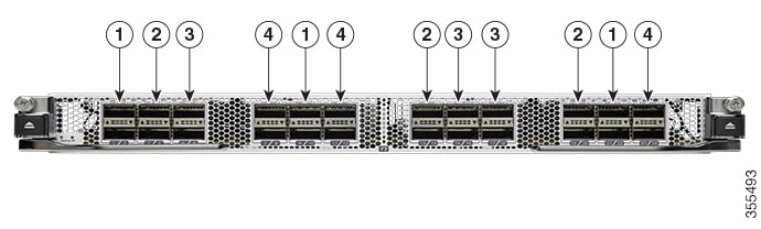
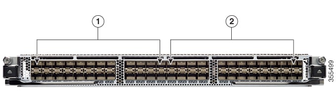
On the Cisco Nexus 7000 Series 48-port, 10-Gbps Ethernet modules N7K-F248XP-25[E] and N7K-F248XT-25[E], you must allocate
the interfaces on your physical device in the specified combination. These modules have 12 port groups that consist of 4 ports
each (4 interfaces x 12 port groups = 48 interfaces). Interfaces that belong to the same port group must belong to the same
VDC.
Figure 2. Example Interface Allocation for Port Groups on the Cisco Nexus 7000 Series 10-Gbps Ethernet Modules N7K-F248XP-25[E] and
N7K-F248XT-25[E] and Cisco Nexus 7700 Series 48-Port 1 and 10-Gbps Ethernet Module N77-F248XP-23E
The callouts in the figure above represent an example of VDC allocation. The table below shows the VDC that each callout represents.
Table 3. Example VDC Allocation
VDC
Callout
VDC A
1
VDC B
2
VDC C
3
VDC D
4
The table below shows the port numbering for the port groups.
Table 4. Port Numbers for Port Groups on the Cisco Nexus 7000 Series 10-Gbps Ethernet Modules N7K-F248XP-25[E] and N7K-F248XT-25[E]
and Cisco Nexus 7700 Series 48-Port 1 and 10-Gbps Ethernet Module N77-F248XP-23E
Port Group
Port Numbers
Group 1
1, 2, 3, 4
Group 2
5, 6, 7, 8
Group 3
9, 10, 11, 12
Group 4
13, 14, 15, 16
Group 5
17, 18, 19, 20
Group 6
21, 22, 23, 24
Group 7
25, 26, 27, 28
Group 8
29, 30, 31, 32
Group 9
33, 34, 35, 36
Group 10
37, 38, 39, 40
Group 11
41, 42, 43, 44
Group 12
45, 46, 47, 48
For more information about port groups on the Cisco Nexus 7000 Series 10-Gbps Ethernet modules, see the Cisco Nexus 7000 Series Hardware Installation and Reference Guide.
Note
When you add or delete interfaces, the Cisco NX-OS software removes the configuration and disables the interfaces.
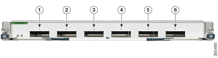
Figure 3. Example Interface Allocation for Port Groups on the Cisco Nexus 7000 Series 100-Gbps Ethernet Modules (N7K-F306CK-25)
The callouts in the figure above represent an example of VDC allocation. The table below shows the VDC that each callout represents.
Table 5. Example VDC Allocation
VDC
Callout
VDC A
1
VDC B
2
VDC C
3
VDC D
4
VDC E
5
VDC F
6
The table below shows the port numbering for the port groups.
Table 6. Port Numbers for Port Groups on the Cisco Nexus 7000 Series 100-Gbps Ethernet Modules (N7K-F306CK-25)
Port Group
Port Numbers
Group 1
1
Group 2
2
Group 3
3
Group 4
4
Group 5
5
Group 6
6
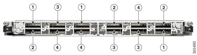
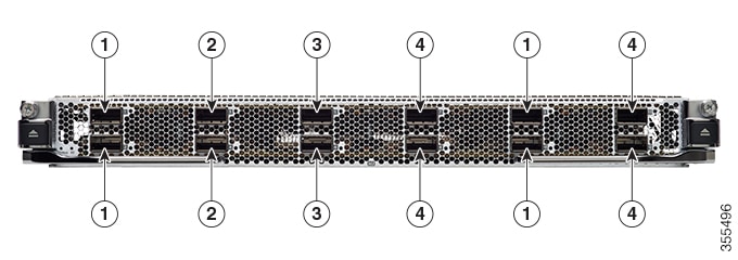
Figure 4. Example Interface Allocation for Port Groups on the Cisco Nexus 7700 Series 100-Gbps Ethernet Modules (N77-F312CK-26)
The callouts in the figure above represent an example of VDC allocation. The table below shows the VDC that each callout represents.
Table 7. Example VDC Allocation
VDC
Callout
VDC A
1
VDC B
2
VDC C
3
VDC D
4
The table below shows the port numbering for the port groups.
Table 8. Port Numbers for Port Groups on the Cisco Nexus 7700 Series 100-Gbps Ethernet Modules (N77-F312CK-26)
Port Group
Port Numbers
Group 1
1
Group 2
2
Group 3
3
Group 4
4
Group 5
5
Group 6
6
Group 7
7
Group 8
8
Group 9
9
Group 10
10
Group 11
11
Group 12
12
Figure 5. Example Interface Allocation for Port Groups on the Cisco Nexus 7000 Series 40-Gbps Ethernet Modules (N7K-F312FQ-25)
The callouts in the figure above represent an example of VDC allocation. The table below shows the VDC that each callout represents.
Table 9. Example VDC Allocation
VDC
Callout
VDC A
1
VDC B
2
VDC C
3
VDC D
4
The table below shows the port numbering for the port groups.
Table 10. Port Numbers for Port Groups on the Cisco Nexus 7000 Series 40-Gbps Ethernet Modules (N7K-F312FQ-25)
Port Group
Port Numbers
Group 1
1, 2
Group 2
3, 4
Group 3
5, 6
Group 4
7, 8
Group 5
9, 10
Group 6
11, 12
Figure 6. Example Interface Allocation for Port Groups on the Cisco Nexus 7700 Series 40-Gbps Ethernet Modules (N77-F324FQ-25)
The callouts in the figure above represent an example of VDC allocation. The table below shows the VDC that each callout represents.
Table 11. Example VDC Allocation
VDC
Callout
VDC A
1
VDC B
2
VDC C
3
VDC D
4
The table below shows the port numbering for the port groups.
Table 12. Port Numbers for Port Groups on the Cisco Nexus 7700 Series 40-Gbps Ethernet Modules (N77-F324FQ-25)
Port Group
Port Numbers
Group 1
1, 2
Group 2
3, 4
Group 3
5, 6
Group 4
7, 8
Group 5
9, 10
Group 6
11, 12
Group 7
13, 14
Group 8
15, 16
Group 9
17, 18
Group 10
19, 20
Group 11
21, 22
Group 12
23, 24
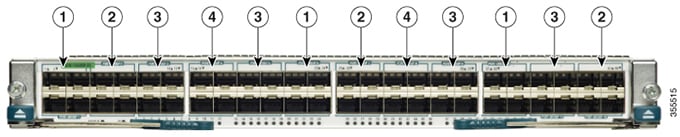
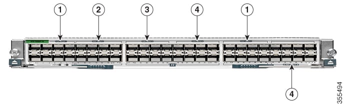
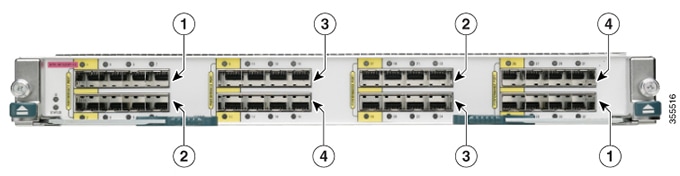
Figure 7. Example Interface Allocation for Port Groups on the Cisco Nexus 7000 Series 10-Gbps Ethernet Modules (N7K-F348XP-25)
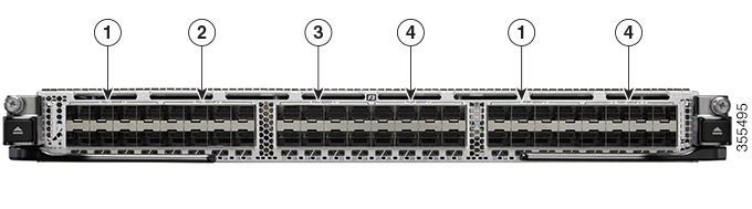
Figure 8. Example Interface Allocation for Port Groups on the Cisco Nexus 7700 Series 10-Gbps Ethernet Modules (N77-F348XP-23)
The callouts in the figures above represent an example of VDC allocation. The table below shows the VDC that each callout
represents.
Table 13. Example VDC Allocation
VDC
Callout
VDC A
1
VDC B
2
VDC C
3
VDC D
4
The table below shows the port numbering for the port groups.
Table 14. Port Numbers for Port Groups on the Cisco Nexus 7000 Series 10-Gbps Ethernet Modules (N7K-F348XP-25) and the Cisco Nexus 7700
Series 10-Gbps Ethernet Modules (N77-F348XP-23)
Port Group
Port Numbers
Group 1
1, 2, 3, 4, 5, 6, 7, 8
Group 2
9, 10, 11, 12, 13, 14, 15, 16
Group 3
17, 18, 19, 20, 21, 22, 23, 24
Group 4
25, 26, 27, 28, 29, 30, 31, 32
Group 5
33, 34, 35, 36, 37, 38, 39, 40
Group 6
41, 42, 43, 44, 45, 46, 47, 48
Figure 9. Example Interface Allocation for Port Groups on the Cisco Nexus 7000 Series 10-Gbps Ethernet Module (N7K-M132XP-12)
The callouts in the figure above represent an example of VDC allocation. The table below shows the VDC that each callout represents.
Table 15. Example VDC Allocation
VDC
Callout
VDC A
1
VDC B
2
VDC C
3
VDC D
4
The table below shows the port numbering for the port groups.
Table 16. Port Numbers for Port Groups on the Cisco Nexus 7000 Series 10-Gbps Ethernet Module N7K-M132XP-12
Port Group
Port Numbers
Group 1
1, 3, 5, 7
Group 2
2, 4, 6, 8
Group 3
9, 11, 13, 15
Group 4
10, 12, 14, 16
Group 5
17, 19, 21, 23
Group 6
18, 20, 22, 24
Group 7
25, 27, 29, 31
Group 8
26, 28, 30, 32
Figure 10. Example Interface Allocation for Port Groups on the Cisco Nexus 7700 Series 100-Gbps Ethernet Modules (N77-M312CQ-26L)
The callouts in the figure above represent an example of VDC allocation. The table below shows the VDC that each callout represents.
Table 17. Example VDC Allocation
VDC
Callout
VDC A
1
VDC B
2
VDC C
3
VDC D
4
The table below shows the port numbering for the port groups.
Table 18. Port Numbers for Port Groups on the Cisco Nexus 7700 Series 100-Gbps Ethernet Modules (N77-M312CQ-26L)
Port Group
Port Numbers
Group 1
1, 2
Group 2
3, 4
Group 3
5, 6
Group 4
7, 8
Group 5
9, 10
Group 6
11, 12
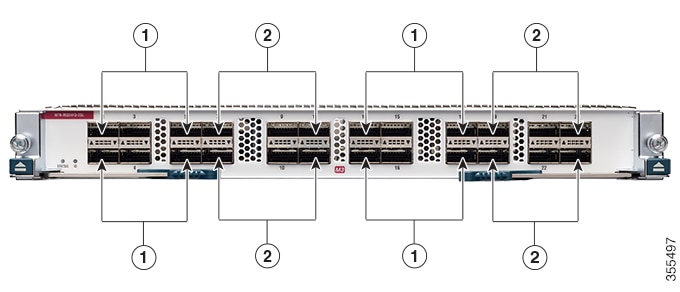
Figure 11. Example Interface Allocation for Port Groups on the Cisco Nexus 7000 Series 40-Gbps Ethernet Modules (N7K-M324FQ-25L)
The callouts in the figure above represent an example of VDC allocation. The table below shows the VDC that each callout represents.
Table 19. Example VDC Allocation
VDC
Callout
VDC A
1
VDC B
2
The table below shows the port numbering for the port groups.
Table 20. Port Numbers for Port Groups on the Cisco Nexus 7000 Series 40-Gbps Ethernet Modules (N7K-M324FQ-25L) and Cisco Nexus 7700
Series 40-Gbps Ethernet Modules (N77-M324FQ-25L)
Port Group
Port Numbers
Group 1
1, 2, 3, 4, 5, 6
Group 2
7, 8, 9, 10, 11, 12
Group 3
13, 14, 15, 16, 17, 18
Group 4
19, 20, 21, 22, 23, 24
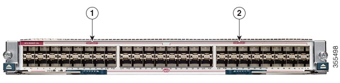
Figure 12. Example Interface Allocation for Port Groups on the Cisco Nexus 7000 Series 10-Gbps Ethernet Modules (N7K-M348XP-25L)
Figure 13. Example Interface Allocation for Port Groups on the Cisco Nexus 7700 Series 10-Gbps Ethernet Modules (N77-M348XP-23L)
Table 21. Example VDC Allocation
VDC
Callout
VDC A
1
VDC B
2
The table below shows the port numbering for the port groups.
Table 22. Port Numbers for Port Groups on the Cisco Nexus 7000 Series 10-Gbps Ethernet Modules (N7K-M348XP-25L) and Cisco Nexus 7700
Series 10-Gbps Ethernet Modules (N77-M348XP-23L)
When interfaces in different VDCs share the same port ASIC, reloading the VDC (with the reload vdc command) or provisioning
interfaces to the VDC (with the allocate interface command) might cause short traffic disruptions (of 1 to 2 seconds) for
these interfaces. If such behavior is undesirable, make sure to allocate all interfaces on the same port ASIC to the same
VDC.
This example shows how to map interfaces to the port ASIC:
The interface number is listed in the FP port column, and the port ASIC number is listed in the MAC_0 column, which means
that in the above example, interfaces 1 through 12 share the same port ASIC (0).
VDC Resource Limits
You can change the resource limits for your VDC individually or by applying a VDC resource template as your needs change.
You can change the following limits for the following resources:
IPv4 multicast route memory
IPv6 multicast route memory
IPv4 unicast route memory
IPv6 unicast route memory
Port channels
Switched Port Analyzer (SPAN) monitor sessions
VLANs
Virtual routing and forwarding (VRF) instances
HA Policies
The HA policy determines the action that the physical device takes when the VDC encounters an unrecoverable error. You can
change the HA policy for the VDC that was specified when you created the VDC.
Note
You cannot change the HA policies for the default VDC.
Saving All VDC Configurations to the Startup Configuration
From the VDC, a user with the vdc-admin or network-admin role can save the VDC configuration to the startup configuration.
However, you might want to save the configuration of all VDCs to the startup configuration from the default VDC.
Suspending and Resuming VDCs
Users with the network-admin role can suspend and resume a nondefault VDC. You must save the VDC running configuration to
the startup configuration before suspending the VDC. Otherwise, you will lose the changes to the running configuration when
you resume the VDC. You cannot remove interfaces allocated to a suspended VDC. All other resources in use by the VDC are released
while the VDC is suspended.
Note
You cannot perform an in-service software upgrade (ISSU) when a VDC is suspended.
Note
You cannot suspend the default VDC.
Caution
Suspending a VDC disrupts all traffic on the VDC.
VDC Reloads
You can reload an active nondefault VDC that is in any state. The impact of reloading a nondefault VDC is similar to reloading
a physical device. The VDC reloads using the startup configuration.
Note
You cannot reload the default or admin VDC.
Caution
Reloading a VDC disrupts all traffic on the VDC.
MAC Addresses
The default VDC has a management MAC address. Beginning with Cisco NX-OS Release 5.2(1) for the Cisco Nexus 7000 Series devices,
subsequent nondefault VDCs that you create are assigned MAC addresses automatically as part of the bootup process.
You will see a syslog message if there are not sufficient MAC addresses to supply all the VDCs on the device.
VDC Boot Order
You can specify the boot order for the VDCs on the Cisco NX-OS device. By default, all VDCs start in parallel with no guarantee
as to which VDC completes starting first. Using the boot order value, the Cisco NX-OS software starts the VDCs in a predictable
sequence. The boot order feature has the following characteristics:
More than one VDC can have the same boot order value. By default, all VDCs have the boot order value of 1.
VDCs with the lowest boot order value boot first.
The Cisco NX-OS software starts all VDCs with the same boot order value followed by the VDCs with the next highest boot order
value.
The Cisco NX-OS software starts VDCs that have the same boot order value in parallel.
You cannot change the boot order for the default VDC or admin VDC; you can change the boot order only for nondefault VDCs.
Prerequisites for Managing VDCs
VDC management has the following prerequisites:
You must have the network-admin user role.
You must log in to the default or admin VDC.
Guidelines and
Limitations for Managing VDCs
VDC management has the
following configuration guidelines and limitations:
Only users with
the network-admin user role can manage VDCs.
You can change
VDCs only from the default or admin VDC.
If sufficient MAC
addresses to program the management port of all the nondefault VDCs are
unavailable, do not program the MAC address in any of the nondefault VDCs.
A syslog message
is generated if sufficient MAC addresses are unavailable to program the
management port in all VDCs.
When a hardware
issue occurs, syslog messages are sent to all VDCs.
When you have
back-to-back connected interfaces in two different virtual routing and
forwarding (VRF) instances within the same VDC, the Address Resolution Protocol
(ARP) fails to complete and packet drops occur because the VRFs obtain their
own source MAC addresses. If you need two interfaces on the same VDC with
different VRFs, assign a static MAC address to the VRF interfaces.
When you replace an I/O module by another I/O module in the same slot of a Cisco Nexus 7000/7700 Series switch and power up
the switch, the new I/O module is powered down and the following syslog message is displayed: Slot-<x> has failed to boot up because of service "Im SAP" due to module insertion failure. To resume normal operations, power up the I/O module after all the VDCs are online. The following syslog message is then
displayed: IM-1-IM_LC_INCOMPATIBLE_COPY_R_S: Module <x> inserted is not compatible with previous module in this slot. To ensure correct
operation, do <copy run start vdc-all> to purge the previous module's configuration. After the I/O module is online, use the copy run start vdc-all command and perform the required configurations.
M2-M3 Interop limitations
The following rules will be enforced for M line modules:
M2 interfaces can coexist with M3 or M2 interfaces in same VDC. However, F2E and M3 interfaces cannot coexist.
No interface from M2 module working with M3 interface can be allocated to other VDC.
M2 module must be in M2-M3 interop mode, if M3 interface exists in same VDC.
M2 module must be in M2-F2E mode, if F2E interface exists in same VDC.
M2 LC must be in M2-M3 mode, if its ports must work in/be allocated to a M2-M3 VDC.
Note
This is applicable even if M3 ports exists or not.
M2 LC must be in M2-F2E mode(default mode), to operate in other VDC.
You must configure interop mode, before applying the ASCII configuration. This avoids applying port related configuration
while LC reboots. For information about M2-M3 VDC and Interoperability mode, see M2-M3 VDC and Interoperability mode.
If the topology configuration consists of any VDC type M2 M3 with ports allocated from a M2 module to this VDC, performing
a write-erase+reload+ascii configuration replay may result in port allocation errors during the configuration replay.
Save the running configuration to the bootflash.
Verify the configuration to contain system interop-mode m2-m3 module x.
Perform write-erase and reload the configuration.
Bring up the switch and verify all the modules are online.
Configure the interop mode using the commands in the saved configuration.
Type Yes when prompted to reload the modules.
Wait until all the modules are Online.
Apply the saved ASCII configuration.
If you reload configuration using reload ascii command, port allocation errors may occur during the configuration replay. Perform the following procedure to troubleshoot.
Save the running configuration to bootflash.
Perform reload ascii.
Wait until all modules and VDCs are online.
Apply the saved ASCII configuration from bootflash.
Along with the above mentioned guidelines and restrictions, the following are applicable from Cisco Nexus 7000 NX-OS Release
7.3(0)DX(1):
Cisco Nexus 7700 series had the following types of M3 module:
Nexus 7700 M3 48-Port 1G/10G Module
Nexus 7700 M3 24-Port 40G
The 48 port 10G module has two sockets of 24 X 10G ASIC.
The 24 port 40G module has four sockets of 6 X 40G ASIC.
The port group mappings are per ASIC.
Interface allocation is done on the port group boundaries. The interfaces align ASIC resources to VDCs.
The port group size varies depending on the module type.
Along with the above mentioned guidelines and restrictions, the following are applicable from Cisco Nexus 7000 NX-OS Release
8.0(1):
Cisco Nexus 7000 Series switches has the following types of M3-Series modules:
The 48 port 10G module has two sockets of 24 X 10G ASIC.
The 24 port 40G module has four sockets of 6 X 40G ASIC.
The 12 port 100G module has six sockets of 2 X 100G ASIC.
The port group mappings are per ASIC.
Interface allocation is done on the port group boundaries. The interfaces align ASIC resources to VDCs.
The port group size varies depending on the module type.
VDC Type Support
The following VDC type support is available in Cisco NX-OS Release 8.0(1):
VDC Type
M3 support
M3 + F3 Support
Layer 2
Yes
Yes
Layer 3
Yes
Yes
Fabric Path
No
No
VxLAN
Yes
Yes
FEX
Yes
Yes
MPLS
Yes
Yes
OTV
Yes
Yes
LISP
Yes
Yes
GTP
Yes
No
Layer 2 Gateways
Yes
No
Table Size
M3 Size
F3 Size
Managing VDCs
Changing the
Nondefault VDC Prompt Format
You can change the
format of the CLI prompt for nondefault VDCs. By default, the prompt format is
a combination of the default VDC name and the nondefault VDC name. You can
change the prompt to only contain the nondefault VDC name.
Before you begin
Log in to the
default or admin VDC with a username that has the network-admin user role.
Procedure
Command or Action
Purpose
Step 1
switch#
configure
terminal
Enters global
configuration mode.
Step 2
switch(config)#
[no]
vdc
combined-hostname
Changes the
format of the CLI prompt for the nondefault VDC. To change the prompt to show
only the nondefault VDC name, use the no format of the command. By default, the
CLI prompt for a nondefault VDC consists of the default VDC name and the
nondefault VDC name.
Copies the
running configuration for all the VDCs to the startup configuration. If you
disable the combined hostname, this command prevents the VDC names from
reverting back to their original format (with combined hostnames) after the
running configuration is saved and the system is reloaded. Enter this command
after turning off the combined hostname.
Allocating
Interfaces to an Ethernet VDC
Note
See the
Cisco NX-OS
FCoE Configuration Guide for Cisco Nexus 7000 and Cisco MDS 9500 for
information on allocating interfaces to storage VDCs for Fibre Channel over
Ethernet (FCoE).
You can allocate one
or more interfaces to a VDC. When you allocate an interface, you move it from
one VDC to another VDC. The interfaces are in the down state after you move
them.
Note
When you
allocate an interface, all configuration on the interface is lost.
Note
Beginning with
Cisco NX-OS Release 5.2(1) for Nexus 7000 Series devices, all members of a port
group are automatically allocated to the VDC when you allocate an interface.
Before you begin
Log in to the
default or admin VDC with a username that has the network-admin user role.
Procedure
Command or Action
Purpose
Step 1
switch#
configure
terminal
Enters global
configuration mode.
Step 2
switch(config)#
vdcvdc-name
Specifies a VDC
and enters VDC configuration mode.
Step 3
(Optional) switch(config-vdc)#
show vdc
membership [status]
Beginning with
Cisco NX-OS Release 6.1(1), you can use the
no allocate interface
ethernet command to remove the interface from the VDC and place
it in an unallocated pool.
Saves the change
persistently through reboots and restarts by copying the running configuration
to the startup configuration.
Note
After you add
an interface to a VDC, you must copy the default or admin VDC running
configuration to the startup configuration before users can copy the changed
VDC running configuration to the startup configuration.
Applying a VDC
Resource Template
You can change the
VDC resource limits by applying a new VDC resource template. Changes to the
limits take effect immediately except for the IPv4 and IPv6 route memory
limits, which take effect after the next VDC reset, physical device reload, or
physical device stateful switchover.
Procedure
Command or Action
Purpose
Step 1
switch#
configure
terminal
Enters global
configuration mode.
Step 2
switch#
show vdc resource
detail
Displays the
resource information for all VDCs.
Step 3
switch(config)#
vdcvdc-name
Specifies a VDC
and enters VDC configuration mode.
Step 4
switch(config-vdc)#
templatetemplate-name
Applies a new
resource template for the VDC.
Step 5
switch(config-vdc)#
exit
Exits VDC
configuration mode.
Step 6
(Optional) switch(config)#
show vdcvdc-nameresource
(Optional)
Displays the
resource information for a specific VDC.
Saves the change
persistently through reboots and restarts by copying the running configuration
to the startup configuration.
Changing VDC
Resource Limits
You can change the
limits on the VDC resources. Changes to the limits take effect immediately
except for the IPv4 and IPv6 routing table memory limits, which take effect
after the next VDC reset, physical device reload, or physical device stateful
switchover.
Note
You can set only one
value for the multicast and unicast route memory resources maximum and minimum
limits. If you specify a minimum limit, that is the value for both the minimum
and maximum limits and the maximum limit is ignored. If you specify only a
maximum limit, that is the value for both the minimum and maximum limits.
Beginning with Cisco
NX-OS Release 6.1, CPU shares are used to control the CPU resources among the
VDCs by allowing you to prioritize VDC access to the CPU during CPU contention.
CPU shares are supported on Supervisor 2/2e modules only. You can also
configure the number of CPU shares on a VDC. For example, a VDC with 10 CPU
shares gets twice the CPU time compared to a VDC that has 5 CPU shares.
Some features require
that all modules in a chassis be of a certain type. Beginning with Cisco NX-OS
Release 6.1(3), you can apply the switchwide VDC mode to prevent accidental
insertion of a module or to restrict certain line cards from powering on in the
system. For example, the result bundle hashing (RBH) modulo feature does not
operate with M Series modules in the system. Use the system module-type command
to apply the switchwide VDC mode. This command controls which line cards are
allowed in the chassis (see the table below). Otherwise, widespread disruption
is caused within a VDC.
The modules that you
do not enable must not be powered on after you configure this feature and enter
yes. An error message forces you to manually disable these modules before
proceeding, which prevents major disruptions and service issues within a VDC.
Beginning with Cisco
NX-OS Release 6.2(2), the F2e Series module can be enabled on the chassis,
which now allows interoperability with the M Series modules. For a chassis with
only F2e Series modules, the default VDC will be created using an F2e Series
module as a supported module unless you apply your own configuration. F2 Series
modules are only compatible with F2e Series modules on the chassis. The F2e and
F2 Series modules cannot exist with the F1 Series module in the same VDCs.
Currently, only F1, F2, and F2e Series modules are supported by storage VDCs.
While Supervisor 1 supports only F1 Series modules in a storage VDC, Supervisor
2/2e supports all these types. The rules of mixing module types in a storage
VDC is the same as in an ethernet VDC.
Note
When using the
system module-type command to apply the switchwide VDC mode, there are no
restrictions on the module types that can be mixed
Modules
F1
F2
F3
F1 with
Supervisor 1 only
Yes
No
No
F2 with
Supervisor 2/2e
No
Yes
Yes
F2 / F2e
with Supervisor 2/2e
No
Yes
Yes
Note
For Cisco NX-OS
Release 6.1 only, because F2e Series modules are supported as F2 Series
modules, F2e Series modules follow the same mixing rules as F2 Series modules.
Note
Storage VDCs in
Cisco NX-OS Release 6.2(6) do not support F3 Series modules.
Table 23. Restrictions and Conditions of Allowed Module Type Mix on Ethernet VDCs
Module
M1
F1
M1XL
M2XL
F2
F2e
F3
M3
M1
Yes
Yes
Yes
Yes
No
Yes
No
No
F1
Yes
Yes
Yes
Yes
No
No
No
No
M1XL
Yes
Yes
Yes
Yes
No
Yes
No
No
M2XL
Yes
Yes
Yes
Yes
No
Yes
Yes
Yes
F2
No
No
No
No
Yes
Yes
Yes
No
F2e
Yes
No
Yes
Yes
Yes
Yes
Yes
No
F3
No
No
No
Yes
Yes
Yes
Yes
Yes
M3
No
No
No
Yes
No
No
Yes
Yes
Note
F3 F2E M2XL cannot coexist in the same VDC (although any two of them can coexist).
Table 24. Module Type
Support on a Default VDC
Cisco NX-OS
Release
All Line
Cards Present in Chassis
Default
Module Type Support for Default VDC (without user configuration)
5.1
M (any)
and/or F1
M1 F1
6.0
F2
M* and/or F1
(and any other combination)
F2
M1 F1
6.1
F2 and/or
F2e
Note
During an
upgrade from Cisco NX-OS Release 6.1x to 6.2(2), F2 Series module type is
automatically upgraded to F2 F2e Series.
F2
6.2
F2
F2e
F2 F2e
F3
F2e F3
Other
combinations
Note
Support
for F3 Series modules was added in Cisco NX-OS Release 6.2(6).
F2 F2e
F2e
F2 F2e
F3
F3 F2e
M1 M1XL M2XL
F2e
7.3(1)D1(1)
F2
F2e
F2 F2e
F3
F2e F3
M1
M2
F2
F2e
F2 F2e
F3
F2e F3
M1
M2
7.3(0)DX(1)
F2
F2e
F2 F2e
F3
F2e F3
M1
M2
M2 M3
M3
F3 M3 (Cisco Nexus 7700 Series switches only)
F2
F2e
F2 F2e
F3
F2e F3
M1
M2
M2 M3
M3
F3 M3 (Cisco Nexus 7700 Series switches only)
8.0 (1)
F2
F2e
F2 F2e
F3
F2e F3
M2
M2 M3
M3
F3 M3
F2
F2e
F2 F2e
F3
F2e F3
M2
M2 M3
M3
F3 M3
Note
The Cisco Nexus 7710 switch and Cisco Nexus 7718 switch supports F2e and F3 Series module types in both an Ethernet VDC and
Storage VDC. F3 Series modules do not support storage VDCs in Cisco NX-OS Release 6.2(6).
Fabric-1 modules, F1 Series modules, M1 Series modules (non-XL mode), and Cisco Nexus 7000 Supervisor-1 modules are not supported
in Cisco NX-OS Release 7.3(0)D1(1) and later releases.
F2e Proxy
Mode
To support the
coexistence of an F2e Series module with an M Series module in the same VDC,
the F2e Series module operates in a proxy mode so that all Layer 3 traffic is
sent to an M Series module in the same VDC. For F2e proxy mode, having routing
adjacencies connected through F2e interfaces with an M1 Series module is not
supported. However, routing adjacencies connected through F2e interfaces with
an M2 Series module is supported.
You cannot allocate
F2e ports as shared interfaces in the storage VDC if the F2e port is in proxy
mode in the Ethernet VDC.
When you enter the
limit-resource module-type command and it changes the
F2e mode between the old VDC type and the new VDC type, you are prompted to
enter the
rebind
interface command, as shown below:
switch(config-vdc)# limit-resource module-type m1 m1xl m2xl f2e
This will cause all ports of unallowed types to be removed from this vdc. Continue (y/n)?
[yes]
Note: rebind interface is needed for proper system operation.
Please backup the running-configuration for interface by redirecting the output of "show
running-config interface".
Reapply the interface configuration after the "rebind interface" command
switch(config)# vdc vdc2
switch(config-vdc)# rebind interfaces
All interfaces' configurations of the current vdc will be lost during interface rebind.
Please back up the configurations of the current vdc. Do you want to proceed (y/n)? [no] yes
switch(config-vdc)#
Note
If an interface rebind is required, users are displayed with a
yes/no prompt on Cisco NX-OS Release 6.2(8) and later, as opposed to entering
the rebind interface command manually in earlier releases.
The table below shows
the VDC type changes that require the rebind interface command:
Table 25. VDC Types That Require Rebind Interface Command
Old VDC Type
New VDC Type
Rebind
Required
Description
Impact
F2,F2e
M,F2e
Yes
Changes F2e
from Layer 3 to proxy mode.
You will lose
the F2,F2e configuration during the rebinding of the interface. F2
configuration loss should not have much impact because F2 ports are not part of
the new VDC.
M,F2e
F2,F2e
Yes
Changes F2e
from proxy to Layer 3 mode.
You will lose
the M,F2e configuration during the rebinding of the interface. M configuration
loss should not have much impact because M ports are not part of the new VDC.
F2e
M,F2e
Yes
Changes F2e
from Layer 3 to proxy mode.
You will lose
only the F2e configuration.
M,F2e
F2e
Yes
Changes F2e
from proxy to Layer 3 mode.
You will lose
the M,F2e configuration during the rebinding of the interface. M configuration
loss should not have much impact because M ports are not part of the new VDC.
F2,F2e
F2e
Yes
Enables
F2e-only capabilities like SVI statistics.
You will lose
the F2,F2e configuration during the rebinding of the interface. F2
configuration loss should not have much impact because F2 ports are not part of
the new VDC.
F2e
F2e,F3
No
N/A
N/A
F2e
F2,F2e
Yes
Disables
F2e-only capabilities like SVI statistics.
You will lose
only the F2e configuration.
F3
F3,F2e
No
N/A
N/A
F3,F2e
F3
No
N/A
N/A
F3
F3,M2XL
No
N/A
N/A
F3,M2XL
F3
No
N/A
N/A
F3,F2,F2e
F3
Yes
Changes LCD to
F3.
You will lose
the F3 configuration.
F3
F3,F2,F2e
Yes
Changes F3
to LCD.
You will
lose the F3 configuration.
F3,F2
F3
Yes
Changes LCD
to F3.
You will
lose the F3 configuration.
F3
F3,F2
Yes
Changes F3
to LCD.
You will
lose the F3 configuration.
M3
M3, F3
Yes
N/A
N/A
M3, F3
M3
Yes
N/A
N/A
M3
M3, M2
Yes
N/A
N/A
M3, M2
M3
Yes
N/A
N/A
Note
M1 and F3 modules cannot co-exist. When an existing module (for exaxmple, M1) is replaced with a new module (for example,
F3) rebind is not required. Rebind is required only when a VDC module type is changed along with the existing module types.
M2-M3 VDC and Interoperability mode
In Cisco Nexus 7000 Series Switches, the M2 line module packet supports both M2-F2E and M2-M3 interop header formats. By default,
the M2 module operates in the M2-F2E mode. M3 line module supports M2-M3 interop header only. M2 and F3/F2E modules supports
both modes of operation.
If M2 and M3 modules operates in the same VDC, M2 module must be changed to M2-M3 interop mode. When M2 module works with
M2 or F2E module in proxy mode, M2 module must be in M2-F2E mode.
M2 LC must be in M2-M3 mode, if its ports must work in/be allocated to a M2-M3 VDC.
Note
This is applicable even if M3 ports exists or not.
M2 LC must be in M2-F2E mode(default mode), to operate in other VDC.
To change the M2 module mode,
To change M2 module to M2-M3 interop mode, use the system interop-mode m2-m3 module command.
Enter Y when prompted to reload the module.
To change M2 module to M2-F2E mode, you must unallocate any M2 interfaces from the M2-M3 VDC.
Use the no system interop-mode m2-m3 module command.
Enter Y when prompted to reload the module.
Note
Ensure that all the interfaces from the same M2 module working with the M3 module must be in the same VDC.
Note
You can insert a maximum of ten 24-port 40-Gigabit Ethernet QSFP+ (N7K-M324FQ-25L) I/O modules in the Cisco Nexus 7018 switch.
This I/O module uses 96 VQI per slot. The maximum VQI of a Cisco Nexus 7018 switch is 1024 and a total of eleven 24-port 40-Gigabit
Ethernet QSFP+ I/0 modules will require 1056 VQI. In such a scenario, the eleventh I/O module will attempt to come online
3 times and then will get powered down. During reload of a switch with eleven 24-port 40-Gigabit Ethernet QSFP+ I/0 modules,
the I/O module that comes up last will be powered down.
Configuring VDC Resource Limits
Procedure
Command or Action
Purpose
Step 1
switch# configure terminal
Enters global configuration mode.
Step 2
(Optional) switch(config)# [no] system module-typemodule-type
(Optional)
Enters switchwide VDC mode and specifies which modules can be enabled on a chassis. You can enable a mix of F1, F2, F2e, M1,
M1XL, and M2 Series modules. There are no restrictions on the type of mix allowed for the system module-type command.
Note
Restrictions on the module types that can be mixed in a VDC are controlled by the limit-resource module-type command.
Note
The modules that you do not enable must not be powered on after you configure this feature and enter yes. An error message
forces you to manually disable these modules before proceeding, which prevents major disruptions and service issues within
a VDC.
The no form of this command resets the configuration mode to allow all modules.
Step 3
(Optional) switch(config)# show vdc
(Optional)
Displays which modules are enabled in the chassis.
Step 4
(Optional) switch(config)# show vdc resource detail
(Optional)
Displays the resource information for all VDCs.
Step 5
switch(config)# vdcvdc-name
Specifies a VDC and enters VDC configuration mode.
Configures the SPAN monitor session resource limits. The range is from 0 to 2. The equal-to-min keyword automatically sets
the maximum limit equal to the minimum limit.
Note
You can have a maximum of two SPAN monitoring sessions on your physical device.
Configures the ERSPAN monitor session resource limits. The range is from 0 to 23. The equal-to-min keyword automatically sets
the maximum limit equal to the minimum limit.
Specifies the limits for port channels. The default minimum value is 0. The default maximum value is 768. The range is from
0 to 768. The equal-to-min keyword automatically sets the maximum limit equal to the minimum limit.
Configures the VLAN resource limits. The range is from 16 to 4094. The equal-to-min keyword automatically sets the maximum limit equal to the minimum limit.
Specifies the limits for VRF. The range is from 2 to 4096. The equal-to-min keyword automatically sets the maximum limit equal to the minimum limit.
Step 15
switch(config-vdc)# limit-resource module-typemodule type
Configures the specified line card type. VDCs support the F1, F2, F2e, M1, M1XL, and M2XL Series module types.
Note
F2e Series modules cannot exist in the same VDC with F1 Series modules. The limit-resource module-type command allows a mix of F1, M1, M1XL, and M2XL Series modules or a mix of F2e, M1, M1XL, and M2XL Series modules in the same
VDC.
Note
F2 Series modules cannot exist in the same VDC with F1, M1, M1XL, and M2XL Series modules. Use the limit-resource module-type f2 command to allow only F2 Series modules into a VDC. Use the limit-resource module-type f2 f2e command to enable an F2e Series module in an F2 VDC. The ports from F2 and F2e Series modules can be allocated like any other
ports.
Step 16
switch(config-vdc)# cpu-sharesshares
Sets the number of CPU shares on a VDC. The range is from 1 to 10. For example, a VDC with 10 CPU shares gets twice the CPU
time compared to a VDC that has 5 CPU shares.
Step 17
(Optional) switch(config-vdc)# show vdc detail
(Optional)
Displays the VDC status information.
Step 18
switch(config-vdc)# exit
Exits VDC template configuration mode.
Step 19
(Optional) switch(config)# show vdc vdc-name resource
Saves the change persistently through reboots and restarts by copying the running configuration to the startup configuration.
Displaying show vdc
detail Output
This example
displays the output of show vdc detail command:
switch# show vdc detail

vdc id: 1
vdc name: switch
vdc state: active
vdc mac address: 00:26:51:cb:bf:41
vdc ha policy: RELOAD
vdc dual-sup ha policy: SWITCHOVER
vdc boot Order: 1
CPU Share: 5
CPU Share Percentage: 22%
vdc create time: Wed Jul 18 18:08:15 2012
vdc reload count: 0
vdc restart count: 0
vdc type: Admin
vdc supported linecards: None

vdc id: 2
vdc name: vdc2
vdc state: active
vdc mac address: 00:26:51:cb:bf:42
vdc ha policy: RESTART
vdc dual-sup ha policy: SWITCHOVER
vdc boot Order: 1
CPU Share: 10
CPU Share Percentage: 45%
vdc create time: Wed Jul 18 18:17:14 2012
vdc reload count: 0
vdc restart count: 0
vdc type: Ethernet
vdc supported linecards: m1 f1 m1xl m2xl

vdc id: 3
vdc name: new-vdc
vdc state: active
vdc mac address: 00:26:51:cb:bf:43
vdc ha policy: RESTART
vdc dual-sup ha policy: SWITCHOVER
vdc boot Order: 1
CPU Share: 7
CPU Share Percentage: 31%
vdc create time: Wed Jul 18 18:29:51 2012
vdc reload count: 0
vdc restart count: 0
vdc type: Ethernet
vdc supported linecards: m1 f1 m1xl m2xl
switch#
Changing the HA Policies
You can change the HA policies for a VDC. The VDC HA policies are as follows:
Dual supervisor modules:
Bringdown—Puts the VDC in the failed state.
Restart—Restarts the VDC. This process includes shutting down all the interfaces within that VDC and stopping all the virtualized
services processes. The Cisco NX-OS software restarts all the virtualized services saved in the startup configuration and
brings the interfaces back up with the configuration saved in the startup configuration. Any configuration that you did not
save in the startup configuration prior to the restart is lost.
Switchover—Initiates a supervisor module switchover.
Single supervisor modules:
Bringdown—Puts the VDC in the failed state.
Reload—Reloads the supervisor module.
Caution
With the reload action, any configuration that you did not save in the startup configuration prior to the reload is lost.
Note
The reload action affects all interfaces and all VDCs on the physical device.
Restart—Restarts the VDC. This process includes shutting down all the interfaces within that VDC and stopping all the virtualized
services processes. The Cisco NX-OS software restarts all the virtualized services saved in the startup configuration and
brings the interfaces back up with the configuration saved in the startup configuration. Any configuration that you did not
save in the startup configuration prior to the restart is lost.
Caution
With the reload action, any configuration that you did not save in the startup configuration prior to the reload is lost.
Note
You cannot change the HA policies for the default or admin VDC.
Before you begin
Log in to the default or admin VDC with a username that has the network-admin user role.
Procedure
Command or Action
Purpose
Step 1
switch#
configure terminal
Enters global configuration mode.
Step 2
switch(config)# vdcvdc-name
Specifies a VDC and enters VDC configuration mode.
Configures the HA policy for the VDC. The dual-sup and single-sup keyword values are as follows:
bringdown—Puts the VDC in the failed state.
reload— Initiates a supervisor module switchover for physical devices with two supervisor modules, or reloads physical devices with
one supervisor module.
restart—Takes down the VDC processes and interfaces and restarts it using the startup configuration.
switchover—Initiates a supervisor module switchover.
Note
You cannot change the HA policies for the default or admin VDC.
Copies the running configuration for all the VDCs to the startup configuration.
Suspending a Nondefault VDC
You can suspend an active nondefault VDC. You must save the VDC running configuration to the startup configuration before
suspending the VDC. Otherwise, you will lose the changes to the running configuration.
Note
You cannot suspend the default and admin VDC.
Caution
Suspending a VDC disrupts all traffic on the VDC.
Before you begin
Log in to the default or admin VDC with a username that has the network-admin user role.
Copies the running configuration for all the VDCs to the startup configuration.
Step 2
switch#
configure terminal
Enters global configuration mode.
Step 3
switch(config)# vdcvdc-namesuspend
Suspends a nondefault VDC.
Resuming a Nondefault VDC
You can resume a nondefault VDC from the suspended state. The VDC resumes with the configuration saved in the startup configuration.
Before you begin
Log in to the default or admin VDC with a username that has the network-admin user role.
Procedure
Command or Action
Purpose
Step 1
switch#
configure terminal
Enters global configuration mode.
Step 2
switch(config)# no vdcvdc-namesuspend
Resumes a suspended nondefault VDC.
Reloading a Nondefault VDC
You can reload a nondefault VDC that is in a failed state. The VDC reloads using the startup configuration.
Note
Use the reload command to reload the default or admin VDC. Reloading the default or admin VDC reloads all VDCs on the Cisco NX-OS device.
Caution
Reloading a VDC disrupts all traffic on the VDC.
Before you begin
Log in to the nondefault VDC with a username that has the vdc-admin user role or use the switchto vdc command from the default or admin VDC to access the nondefault VDC.
Copies the running configuration for the nondefault VDC to the startup configuration.
Step 2
switch-TestVDC# reload vdc
Reloads a nondefault VDC.
Configuring the VDC Boot Order
You can configure the boot order for the VDCs on your Cisco NX-OS device.
Note
You cannot change the boot order of the default or admin VDC.
Before you begin
Log in to the default or admin VDC with a username that has the network-admin user role.
Procedure
Command or Action
Purpose
Step 1
switch#
configure terminal
Enters global configuration mode.
Step 2
switch(config)# vdcvdc-name
Specifies a VDC and enters VDC configuration mode.
Step 3
switch(config-vdc)# boot-ordernumber
Configures the boot order value for the VDC. The range for the number argument is from 1 to 4 on a Supervisor 2 module and
from 1 to 8 on a Supervisor 2e module. The VDC starts from the lowest to the highest boot order value.
You cannot change the boot order for the default VDC.
Copies the
running configuration to the startup configuration.
Verifying the VDC Configuration
To display the VDC configuration, perform one of the following tasks:
Command
Purpose
show running-config {vdc | vdc-all}
Displays the VDC information in the running configuration.
show vdc [vdc-name]
Displays the VDC configuration information.
show vdc detail
Displays the detailed information about many VDC parameters.
show vdc current-vdc
Displays the current VDC number.
show vdc membership [status]
Displays the VDC interface membership information.
show vdc resource template
Displays the VDC template configuration.
show resource
Displays the VDC resource configuration for the current VDC.
show vdc [vdc-name] resource [resource-name]
Displays the VDC resource configuration for all VDCs.
show mac vdc {vdc-id}
Displays the MAC address for a specific VDC.
For detailed information about the fields in the output from these commands, see the Cisco Nexus 7000 Series NX-OS Virtual Device Context Command Reference.
Configuration Examples for VDC Management
This example shows how to allocate interfaces between VDCs for port groups on a Cisco Nexus 7000 Series 32-port, 10-Gbps Ethernet
module:
Note
VDC-A is the default VDC.
config t
hostname VDC-A
vdc VDC-B
! Port group 2
allocate interfaces ethernet 2/2, ethernet 2/4, ethernet 2/6, ethernet 2/8
! Port group 3
allocate interfaces ethernet 2/9, ethernet 2/11, ethernet 2/13, ethernet 2/15
vdc VDC-C
! Port group 4
allocate interfaces ethernet 2/10, ethernet 2/12, ethernet 2/14, ethernet 2/16
! Port group 5
allocate interfaces ethernet 2/17, ethernet 2/19, ethernet 2/21, ethernet 2/23
vdc VDC-D
! Port group 6
allocate interfaces ethernet 2/18, ethernet 2/20, ethernet 2/22, ethernet 2/24
! Port group 7
allocate interfaces ethernet 2/25, ethernet 2/27, ethernet 2/29, ethernet 2/30
Related Documents for Managing VDCs
Related
Topic
Document
Title
Cisco
NX-OS licensing
Cisco Nexus 7000 Series NX-OS Unicast Routing Command Reference
Cisco Nexus 7000 Series Hardware Installation and Reference Guide
Cisco Nexus 7000 Series
Hardware Installation and Reference Guide
VDC
commands
Cisco Nexus 7000 Series NX-OS
Virtual Device Context Command Reference
FCoE
commands
Cisco NX-OS FCoE Command
Reference for Cisco Nexus 7000 and Cisco MDS 9500
Feature History for
Managing VDCs
This table includes only the updates for those releases that have resulted in additions or changes to the feature.
Table 26. Feature History
for Managing VDCs
Feature Name
Release
Feature Information
M3 Series Module
8.0(1)
Added guidelines and limitations for support of M3 Series modules on Cisco Nexus 7000 Series switches.
M3 Series Module
7.3(0)DX(1)
Added guidelines and limitations for support of M3 Series modules on Cisco Nexus 7700 Series switches.
F3 Series
module
6.2(6)
Added
support for the F3 Series module.
Cisco Nexus
7710 switch and Cisco Nexus 7718 switch
6.2(2)
Added
support for the Cisco Nexus 7710 switch and the Cisco Nexus 7718 switch on the
Supervisor 2e module.
Admin VDC on
Supervisor 1 module
6.2(2)
Added
support for admin VDCs on the Supervisor 1 module.
F2e Series
module
6.2(2)
Added the
ability to enable the F2e Series module (a new configurable VDC module type,
independent from and separate to the F2 VDC module type) on the chassis.
F2e proxy
mode
6.2(2)
Introduced
this feature to support the coexistence of an F2e Series module with an M
Series module in the same VDC.
Switchwide
VDC mode
6.1(3)
Added the
ability to enable specific line cards in the chassis and prevent others from
powering on.
Support for
F2e Series modules
6.1(2)
Added
support for F2e Series modules as part of the F2 Series modules.
Support for
Supervisor 2 and M2 Series modules.
6.1(1)
Added
support for Supervisor 2 and M2 Series modules.
CPU shares
6.1(1)
Added
support for CPU shares on a VDC.
VDC resource
limits
6.0(1)
Added
support for F2 Series modules.
MAC
addresses
5.2(1)
The default
VDC has a MAC address, and subsequent nondefault VDCs that are created are
assigned MAC addresses.
VDC resource
limits
5.2(1)
Added
support for M1XL Series modules.
N7K-F132XP-15 module
5.1(1)
Added
support for the N7K-F132XP-15 module.
VDC
resource limits
5.1(1)
Added the
ability to configure ERSPAN monitor session resource limits.
VDC
resource limits
5.0(2)
The range
for the minimum and maximum values changed for the
limit-resource
m4route-mem,
limit-resource
m6route-mem,
limit-resource
u4route-mem,
limit-resource
u6route-mem, and
limit-resource
vrf commands.
Restarting
VDCs
4.2(4)
The vdc
restart command was replaced by the
reload vdc
command.
Suspending
and resuming VDCs
4.2(1)
You can
suspend and resume nondefault VDCs.
Restarting
VDCs
4.2(1)
You can
restart active nondefault VDCs and nondefault VDCs in the failed state.
Reloading
VDCs
4.2(1)
You can
reload nondefault VDCs.
VDC prompt
format
4.2(1)
You can
change the format of the CLI prompt for nondefault VDCs.
VDC boot
order
4.2(1)
You can
configure the boot order for nondefault VDCs.
IPv4
unicast route memory resource
4.1(2)
Changed
the default maximum value from 256 to 8.
IPv6
unicast route memory resource
4.1(2)
Changed
the default maximum value from 256 to 4.
Multicast
route memory resources
4.1(2)
Added IPv4
and IPv6 multicast route memory resources.
Port
channel resources
4.1(2)
Changed
the default maximum value from 256 to 768.
IPv4
unicast route memory resource
4.0(2)
Changed
the default maximum value from 256 to 320.
IPv6
unicast route memory resource
4.0(2)
Changed
the default maximum value from 256 to 192.


 Feedback