Cisco Nexus 7000 Series NX-OS Fundamentals Configuration Guide 8.x
Bias-Free Language
The documentation set for this product strives to use bias-free language. For the purposes of this documentation set, bias-free is defined as language that does not imply discrimination based on age, disability, gender, racial identity, ethnic identity, sexual orientation, socioeconomic status, and intersectionality. Exceptions may be present in the documentation due to language that is hardcoded in the user interfaces of the product software, language used based on RFP documentation, or language that is used by a referenced third-party product. Learn more about how Cisco is using Inclusive Language.
This chapter
provides information about the Network Plug and Play (PnP) feature in the Cisco
Nexus 7000 Series Switches, and contains the following sections:
Finding Feature
Information
Your software release might not support all the features documented in this module. For the latest caveats and feature information,
see the Bug Search Tool at https://tools.cisco.com/bugsearch/ and the release notes for your software release. To find information about the features documented in this module, and to
see a list of the releases in which each feature is supported, see the “New and Changed Information” section or the "Feature
History" table.
Feature History
for Network Plug and Play
This table
lists the release history for this feature.
Table 1. Feature
History for Network Plug and Play
Feature
Name
Releases
Feature
Information
Network
Plug and Play
8.2(1)
This
feature was introduced.
Network Plug and Play (PnP) is a software application that
runs on a Cisco Nexus 7000 Series Switch. The PnP feature provides a simple,
secure, unified, and integrated offering to make a new branch or campus
rollouts much easier, or for provisioning updates to an existing or a new
network. This feature provides a unified approach to provision networks
comprising multiple devices with a near-zero-touch deployment experience.
Information About
Network Plug and Play
Network Plug and
Play (PnP) is a software application that runs on a Cisco Nexus 7000 Series
Switch. The PnP feature provides a simple, secure, unified, and integrated
offering to make a new branch or campus rollouts much easier, or for
provisioning updates to an existing or a new network. This feature provides a
unified approach to provision networks comprising multiple devices with a
near-zero-touch deployment experience.
Simplified
deployment reduces the cost and complexity and increases the speed and security
of the deployments. The PnP feature helps simplify the deployment of any Cisco
device by automating the following deployment-related operational tasks:
Establishing initial
network connectivity for a device.
Delivering device
configuration to the controller.
Delivering software and
firmware images to the controller.
Delivering licenses to the
controller.
Delivering deployment
script files to the controller.
Provisioning local
credentials of a switch.
Notifying other management
systems about deployment-related events.
The PnP is a
client-server based model. The client (agent) runs on a Cisco Nexus 7000 Series
Switch and the server (controller) runs on the Cisco DNA Controller.
PnP uses a secure
connection to communicate between the agent and the controller. This
communication is encrypted.
The PnP agent
converge solutions that exist in a network into a unified agent and adds
additional functionality to enhance the current solutions. The main objectives
of the PnP agent are:
Provide consistent Day 0
deployment solution for all the deployment scenarios.
Add new or required
features to improve existing solutions.
Provide Day 2 management
framework mainly in the context of configuration and image upgrades.
Features
Provided by the Network Plug and Play (PnP) Agent
Some of the
features that the PnP agent provides are:
Day 0 bootstrapping. This
includes the configuration, image, licenses, and other files.
Day 2 management. This
includes the configuration and image upgrades and ongoing monitoring of Simple
Network Management Protocol (SNMP) and syslog messages.
Open communication
protocol. This enables customers and partners to write applications.
XML-based payload over
HTTP.
Security. This includes
authentication and encrypted communication channel between the management app
and the agent.
Deployment and management
of devices behind firewall and Network Address Translation (NAT).
Support for one-to-one and
one-to-many communication.
Support for policy-based
deployment (product ID or location of the device).
Deployment based on
unique ID (Unique Device Identifier [UDI] or MAC).
Support for various
deployment scenarios and use cases.
Zero-touch deployment is
performed whenever possible. Low-touch deployment is performed based on the
need.
When a device is
powered on for the first time, the PnP discovery process, which is embedded in
the device, gets enabled in the absence of a startup configuration file and
attempts to discover the address of the PnP controller or server. The PnP agent
uses methods such as DHCP, Domain Name System (DNS), and others to acquire the
desired IP address of the PnP server.
When the PnP
agent successfully acquires the IP address, it initiates a long-term,
bidirectional Layer 3 connection with the server and waits for a message from
the server. The PnP server application sends messages to the corresponding
agent, requesting for information about the devices and the services to be
performed on the device.
The agent
running on the Cisco Nexus 7000 Series switch then configures the IP address on
receiving the DHCP acknowledgment and establishes a secure channel with the
controller to provision the configurations. The switch then upgrades the image
and applies the configurations.
Discovery
Methods
A PnP agent
discovers the PnP controller or server using one of the following methods:
DHCP-based discovery
DNS-based discovery
PnP connect
After the
discovery, the PnP agent writes the discovered information into a file, which
is then used to handshake with the PnP server (DNA controller/APIC-EM).
The following
tasks are carried out by the agent in the PnP discovery phase:
Brings up all the
interfaces.
Sends a DHCP request in
parallel for all the interfaces.
On receiving a DHCP
reply, configures the IP address and mask, default route, DNS server, domain
name, and writes the PnP server IP in a lease-parsing file. Note that there is
no DHCP client in Cisco Nexus Switches and static configuration is required.
Brings down all the
interfaces.
DHCP-Based Discovery
When the switch
is powered on and if there is no startup configuration, the PnP starts with
DHCP discovery. DHCP discovery obtains the PnP server connectivity details.
The PnP agent
configures the following:
IP address
Netmask
Default gateway
DNS server
Domain name
If the agent
configuration fails, you should manually intervene and configure the switch.
DHCP discovery
has the following flow:
Power on the switch.
Switch will boot up, the
PnP process will be started, as there is no configuration present.
Start DHCP discovery.
DHCP Server replies with
the PnP agent and the PnP server configuration.
PnP agent handshakes with
the PnP server.
Download the image,
install, and reload.
Download and apply the
configuration from the controller.
Reload the switch.
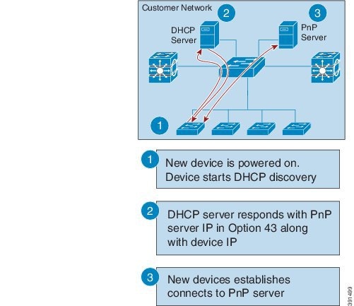
A device with no
startup configuration in the NV-RAM triggers the PnP agent to initiate a DHCP
discovery process, which acquires the IP configuration from the DHCP server
required for the device. The DHCP server can be configured to insert additional
information using vendor-specific Option 43. Upon receiving Option 60 from the
device with the string (cisco pnp), to pass on the IP address or hostname of
the PnP server to the requesting device. When the DHCP response is received by
the device, the PnP agent extracts the Option 43 from the response to get the
IP address or the hostname of the PnP server. The PnP agent then uses this IP
address or hostname to communicate with the PnP server.
Figure 1. DHCP
Discovery Process for PnP Server
DNS-Based Discovery
When the DHCP
discovery fails to get the PnP server, the agent falls back to DNS-based
discovery. To start the DNS-based discovery, the following information is
required from DHCP:
IP address and netmask
Default gateway
DNS server IP
Domain name
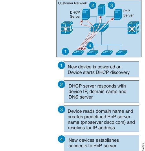
The agent
obtains the domain name of the customer network from the DHCP response and
constructs the fully qualified domain name (FQDN). The following FQDN is
constructed by the PnP agent using a preset deployment server name and the
domain name information for the DHCP response. The agent then looks up the
local name server and tries to resolve the IP address for the above FQDN.
Figure 2. DNS
Lookup for pnpserver.[domainname].com
Note
The device
reads domain name and creates predefined PnP server name as pnpserver.[domain
name].com, for example; pnpserver.cisco.com.
Plug and Play Connect
When the DHCP
and the DNS discovery fail, the PnP agent discovers and communicates with Cisco
Cloud-based deployment service for initial deployment. The PnP agent directly
opens an HTTPS channel using the Python library, which internally invokes
OpenSSL to talk with cloud for configuration.
Cisco Power
On Auto Provisioning
Cisco Power On
Auto Provisioning (PoAP) communicates with the DHCP and TFTP servers to
download the image and configurations. With the introduction of the PnP
feature, PnP and PoAP coexist together in a Cisco Nexus 7000 switch. PoAP and
PnP interworking has the following processes:
PoAP starts first no
configuration is present in the system.
PnP starts later if PoAP
does not get provisioned.
PoAP and PnP discover the
controller alternatively.
The controller discovery
process continues until a controller or until the admin aborts auto provision.
The process (POAP or PnP)
that finds the controller continues provisioning and the other process that
does not find the controller is notified and eventually terminated.
Services and Capabilities
of the Network Plug and Play Agent
The PnP agent
performs the following tasks:
Backoff
Capability
CLI execution
Configuration upgrade
Device information
Certificate install
Image install
Redirection
Note
The PnP
controller or server provides an optional checksum tag to be used in the image
installation and configuration upgrade service requests by the PnP agent. When
the checksum is provided in a request, the image install process compares the
checksum against the current running image checksum.
If the
checksums are same, the image being installed or upgraded is the same as the
current image running on the device. The image install process will not perform
any other operation in this scenario.
If the
checksums are not the same, the new image will be copied to the local file
system, and the checksum will be calculated again and compared with the
checksum provided in the request. If they are the same, the image install
process continues to install the new image or upgrade the device to the new
image. If the checksums are not the same, the process exits with an error.
Backoff
A Cisco NX-OS
device that supports PnP protocol, which uses HTTP transport, requires the PnP
agent to send the work request to the PnP server continuously. If the PnP
server does not have any scheduled or outstanding PnP service for the PnP agent
to execute, the continuous no-operation work requests exhaust both the network
bandwidth and the device resources. This PnP backoff service allows the PnP
server to inform the PnP agent to rest for the specified time and call back
later.
Capability
Capability
service request is sent by the PnP server to the PnP agent on a device to query
the supported services by the agent. The server then sends an inventory service
request to query the device's inventory information; and then sends an image
installation request to download an image and install it. After getting the
response from the agent, the list of supported PnP services and features are
enlisted and returned back to the Server.
CLI Execution
Cisco NX-OS
supports two modes of command execution, privileged EXEC mode and global
configuration mode. Most of the EXEC commands are one-time commands, such as
show commands, which show the current configuration status, and
clear commands, which clear counters or interfaces. The EXEC commands are not
saved when a device reboots. Configuration mode commands allow user to make
changes to the running configuration. If you save the configuration, these
commands are saved when a device reboots.
Configuration Upgrade
Two types of
configuration upgrades takes place in a Cisco device—copying new configuration
files to the startup configuration and copying new configuration files to the
running configuration.
Copying new
configuration files to the startup configuration—A new configuration file is
copied from the file server to the device using the
copy
command, and the file check task is performed to check the validity
of the file. If the file is valid, the file is copied to the startup
configuration. The previous configuration file is backed up if enough disk
space is available. The new configuration comes into effect when the device
reloads again.
Copying new
configuration files to the running configuration—A new configuration file is
copied from the file server to the device using the
copy command or
configure replace command. Replace and rollback of configuration
files may leave the system in an unstable state if rollback is performed
inefficiently. Therefore, configuration upgrade by copying the files is
preferred.
Device
Information
The PnP agent
provides the capability to extract device inventory and other important
information to the PnP server on request. The following device-profile request
types are supported:
all—Returns complete
inventory information, which includes unique device identifier (UDI), image,
hardware, and file system inventory data.
filesystem—Returns file
system inventory information, which includes file system name and type, local
size (in bytes), free size (in bytes), read flag, and write flag.
hardware—Returns hardware
inventory information, which includes hostname, vendor string, platform name,
processor type, hardware revision, main memory size, I/O memory size, board ID,
board rework ID, processor revision, mid-plane revision, and location.
image—Returns image
inventory information, which includes version string, image name, boot
variable, return to ROMMON reason, bootloader variable, configuration register,
configuration register on next boot, and configuration variables.
UDI—Returns the device
UDI.
Certificate Install
Certificate
install is a security service through which a PnP server requests the PnP agent
on a device for trust pool or trust point certificate installation or
uninstallation. This service also specifies the agent about the primary and
backup servers for reconnection. The following prerequisites are required for a
successful certificate installation:
The server from which the
certificate or trust pool bundle needs to be downloaded should be reachable.
There should not be any
permission issues to download the certificate or the bundle.
The PKI API should be
available and accessible for the PnP agent so that the agent could call to
download and install the certificate or the bundle.
There is enough memory on
the device to save the downloaded certificate or bundle.
Image Install
The image
install service enables a PnP-enabled device to perform image upgrade on
receiving a request from the PnP server.
An Image Install
request can be made for the following types of devices:
Standalone devices
High-availability devices
Stackable devices
Cisco Nexus 7000 Series
devices
Standalone
Devices
When the PnP
agent on a standalone device receives a request from the PnP server, the agent
parses the XML payload and identifies the request as an Image Upgrade request.
The agent then creates an ImageInstall process, which identifies the request as
a standalone image install request.
High-Availability Devices
When the PnP
agent is installed on a high-availability device, and the ImageInstall service
gets the data structure, the agent determines if the request is for a
high-availability device. The active route processor (RP) that is running the
PnP agent performs all the tasks required to install the image on both the
active and standby devices.
Redirection
The Redirection
service is used to redirect a device to another controller.
PnP Agent
The PnP agent is
an embedded software component that is present in all Cisco network devices
that support simplified deployment architecture. The PnP agent understands and
interacts only with a PnP server. The PnP agent first tries to discover a PnP
server, with which it can communicate. After a server is found and connection
established, the agent performs deployment-related activities such as
configuration, image, license, and file updates by communicating with the
server. It also notifies the server of all interesting deployment-related
events such as out-of-band configuration changes and new device connections on
an interface.
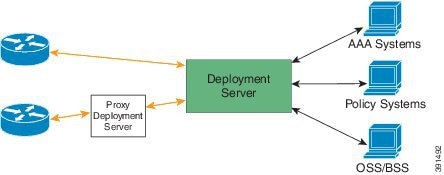
PnP Server
The PnP server
is a central server that encodes the logic of managing and distributing
deployment information (images, configurations, files, and licenses) for the
devices being deployed. The server communicates with the agent on the device
that supports the simplified deployment process using a specific deployment
protocol.
Figure 3.
Simplified Deployment Server
The PnP server
also communicates with proxy servers such as deployment applications on smart
phones and PCs, or other PnP agents acting as Neighbor Assisted Provisioning
Protocol (NAPP) servers, and other types of proxy deployment servers such as
VPN gateways.
The PnP server
can redirect the PnP agent to another deployment server. A common example of
redirection is a PnP server redirecting a device to communicate with it
directly after sending the bootstrap configuration through a NAPP server. A PnP
server can be hosted by an enterprise. This solution allows for a cloud-based
deployment service provided by Cisco. In this case, a device discovers and
communicates with Cisco cloud-based deployment service for initial deployment.
After that, it can be redirected to the customer's deployment server.
In addition to
communicating with the devices, the server interfaces with a variety of
external systems such as authentication, authorizing, and accounting (AAA)
systems, provisioning systems, and other management applications.
PnP Agent
Deployment
The following
steps indicate the PnP agent deployment procedure on Cisco devices:
A Cisco device with a PnP
agent contacts the PnP server, requesting for a task, that is, the PnP agent
sends UDI along with a request for work.
If the PnP server has a
task for the device, for example, image installation, configuration, upgrade,
and so on, it sends a work request.
After the PnP agent
receives the work request, it executes the task and sends back a reply to the
PnP server about the task status, that is whether it is successful or if an
error has occurred, and the corresponding information that is requested.
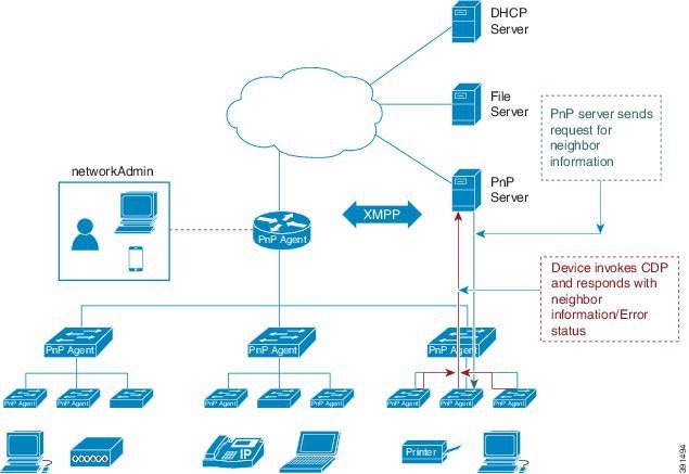
PnP Agent
Network Topology
Figure 4. Network Topology of Cisco
PnP Agent Deployment
PnP Agent
Initialization
The PnP agent is
enabled by default, but can be initiated on a device when the startup
configuration is not available.
Absence of
Startup Configuration
New Cisco
devices are shipped to customers with no startup configuration file in the
NVRAM of the devices. When a new device is connected to a network and powered
on, the absence of a startup configuration file on the device automatically
triggers the PnP agent to discover the PnP server IP address.
CLI
Configuration for the PnP Agent
PnP supports
devices that are using VLAN 1 by default. To use a VLAN other than 1, adjacent
upstream devices must configure the
pnp
startup-vlanvlan-id
command on the upstream device.
This
configuration on the upstream switch directs the VLAN that needs to be
configured by the downstream switch for PnP provisioning. The VLAN value is
exchanged with the downstream switch using Cisco Discovery Protocol (CDP) type,
length, values (TLVs). All the inband ports of the downstream switch are
configured as a trunk on receiving the
pnp startup
vlan from CDP TLV for Day 0 provisioning.
Guidelines for the PnP
Deployment
The PnP deployment method
depends on the discovery process required for finding the PnP controller or
server.
The discovery mechanism
should be deployed, either as a DHCP server discovery process or a Domain Name
Server (DNS) discovery process, before launching PnP.
The DHCP server or the
DNS server should be configured before deploying PnP.
The PnP server should
communicate with the PnP agent.
PnP connect does not
require a DHCP or DNS configuration.
PnP runs both the in-band
and the management interfaces.
IPv6 support for PnP is
not available for Cisco Nexus 7000 Series devices.
The kickstart and system
images must be bundled into a tar file to update in APIC-EM.
The bootflash should have
enough space to download the image and configurations from APIC-EM.
Configuring the
Upstream Switch to Broadcast PnP
Configure and
Start the DPT capture
Procedure
Step 1
Enable the
global configuration mode.
Example:
switch#configure terminal
Step 2
Configure the
upstream switch to broadcast PnP VLAN over the Cisco Discovery Protocol (CDP):
Example:
switch(config)# pnp startup-vlan vlan ID
Note
To use a
VLAN other than 1, adjacent upstream devices must configure the
pnp
startup-vlanvlan-id command on the upstream device. This configuration
must be performed to push this command to the upcoming PnP device.
When you
execute the
pnp startup-vlanvlan-id command on an adjacent upstream device, the VLAN
membership change does not happen on that device. However, all the active
interfaces on the upcoming PnP device are changed to the specified VLAN.
Step 3
Exit global
configuration mode and enter privileged EXEC mode:

 Feedback