Configuring VLANs

This chapter contains the following sections:

Information About VLANs

Understanding VLANs

A VLAN is a group of end stations in a switched network that is logically segmented by function, project team, or application, without the limitation to the physical locations of the users. VLANs have the same attributes as physical LANs, but you can group end stations even if they are not physically located on the same LAN segment.

Any port can belong to a VLAN; all unicast, broadcast, and multicast packets are forwarded and flooded only to end stations in that VLAN. Each VLAN is considered a logical network. If a packet destination address does not belong to the VLAN, it must be forwarded through a router.

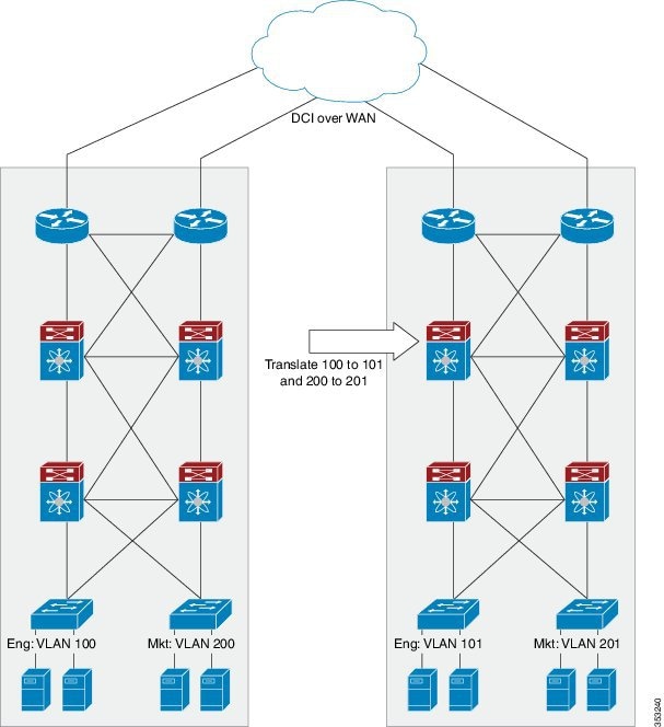
The following figure shows VLANs as logical networks. In this diagram, the stations in the engineering department are assigned to one VLAN, the stations in the marketing department are assigned to another VLAN, and the stations in the accounting department are assigned to yet another VLAN.

Figure 1. VLANs as Logically Defined Networks

VLANs are usually associated with IP subnetworks. For example, all the end stations in a particular IP subnet belong to the same VLAN. To communicate between VLANs, you must route the traffic.

By default, a newly created VLAN is operational. To disable the VLAN use the shutdown command. Additionally, you can configure VLANs to be in the active state (passing traffic), or the suspended state (in which the VLANs are not passing packets). By default, the VLANs are in the active state and pass traffic.


Note

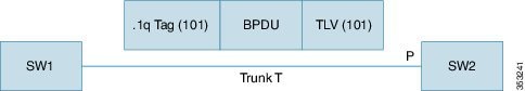
The VLAN Trunking Protocol (VTP) mode is OFF. VTP BPDUs are dropped on all interfaces of the switch. This process has the effect of partitioning VTP domains if other switches have VTP turned on.


Understanding VLAN Ranges

The Cisco Nexus device supports VLAN numbers 1 to 4094 in accordance with the IEEE 802.1Q standard. These VLANs are organized into ranges. The switch is physically limited in the number of VLANs it can support. For information about VLAN configuration limits, see the configuration limits documentation for your device.

The following table describes the details of the VLAN ranges.

Table 1. VLAN Ranges

VLANs Numbers

Range

Usage

1

Normal

Cisco default. You can use this VLAN, but you cannot modify or delete it.

2—1005

Normal

You can create, use, modify, and delete these VLANs.

1006—4094

Extended

You can create, name, and use these VLANs. You cannot change the following parameters:

  • State is always active.

  • VLAN is always enabled. You cannot shut down these VLANs.

3968—4049 and 4094

Internally allocated

These 82 VLANs, plus VLAN 4094, are allocated for internal use. You cannot create, delete, or modify any VLANs within the block reserved for internal use.


Note

You cannot configure the internally allocated VLANs (reserved VLANs).


Note

VLANs 3968 to 4049 and 4094 are reserved for internal use; these VLANs cannot be changed or used.


Cisco NX-OS allocates a group of 82 VLAN numbers for those features, such as multicast and diagnostics, that need to use internal VLANs for their operation. By default, the system allocates VLANs numbered 3968 to 4049 for internal use. VLAN 4094 is also reserved for internal use by the switch.

You cannot use, modify, or delete any of the VLANs in the reserved group. You can display the VLANs that are allocated internally and their associated use.

Creating, Deleting, and Modifying VLANs

VLANs are numbered from 1 to 4094. All configured ports belong to the default VLAN when you first bring up the switch. The default VLAN (VLAN1) uses only default values. You cannot create, delete, or suspend activity in the default VLAN.

You create a VLAN by assigning a number to it. You can delete VLANs as well as move them from the active operational state to the suspended operational state. If you attempt to create a VLAN with an existing VLAN ID, the switch goes into the VLAN submode but does not create the same VLAN again.

Newly created VLANs remain unused until ports are assigned to the specific VLAN. All the ports are assigned to VLAN1 by default.

Depending on the range of the VLAN, you can configure the following parameters for VLANs (except the default VLAN):

  • VLAN name

  • Shutdown or not shutdown

When you delete a specified VLAN, the ports associated to that VLAN are shut down and no traffic flows. However, the system retains all the VLAN-to-port mapping for that VLAN, and when you reenable, or recreate, the specified VLAN, the system automatically reinstates all the original ports to that VLAN.


Note

Commands entered in the VLAN configuration submode are immediately executed.

VLANs 3968 to 4049 and 4094 are reserved for internal use; these VLANs cannot be changed or used.


About the VLAN Trunking Protocol

VLAN Trunking Protocol (VTP) is a distributed VLAN database management protocol that synchronizes the VTP VLAN database across domains. A VTP domain includes one or more network switches that share the same VTP domain name and are connected with trunk interfaces.

Guidelines and Limitations for VTP

VTP has the following configuration guidelines and limitations:

  • When a switch is configured as a VTP client, you cannot create VLANs on the switch in the range of 1 to 1005.

  • VLAN 1 is required on all trunk ports used for switch interconnects if VTP is supported in the network. Disabling VLAN 1 from any of these ports prevents VTP from functioning properly.

  • If you enable VTP, you must configure either version 1 or version 2. On the Cisco Nexus device, 512 VLANs are supported. If these switches are in a distribution network with other switches, the limit remains the same.

    On the Cisco Nexus device, 512 VLANs are supported. If these switches are in a distribution network with other switches, the VLAN limit for the VTP domain is 512. If a Cisco Nexus device client/server receives additional VLANs from a VTP server, they transition to transparent mode.

  • If system vlan long-name knob is enabled, then VTP configurations will come up in OFF mode and users can change the mode to Transparent. However, changing the mode to Server or Client is not allowed.

  • The show running-configuration command does not show VLAN or VTP configuration information for VLANs 1 to 1000.

  • When deployed with vPC, both vPC switches must be configured identically. vPC performs a Type 2 consistency check for VTP configuration parameters.

  • VTP advertisements are not sent out on Cisco Nexus Fabric Extender ports.

  • Private VLANs (PVLANs) are supported only when the switch is in transparent mode.

  • If you are using VTP in a Token Ring environment, you must use version 2.

  • When a switch is configured in VTP client or server mode, VLANs 1002 to1005 are reserved VLANs.

  • VTPv3 pruning is supported from Cisco NX-OS Release 7.2(0)N1(1) onwards.

  • You must enter the copy running-config startup-config command followed by a reload after changing a reserved VLAN range. For example:

    switch(config)# system vlan 2000 reserve 
    This will delete all configs on vlans 2000-2081. Continue anyway? (y/n) [no] y


    After the switch reload, VLANs 2000 to 2081 are reserved for internal use, which requires that you enter the copy running-config startup-config command before the switch reload. Creating VLANs within this range is not allowed.

  • Ensure VLAN 1 is not STP blocked for VTP interfaces in VTP transparent mode.

  • In SNMP, the vlanTrunkPortVtpEnabled object indicates whether the VTP feature is enabled or not.

About VLAN Translation

In a data center there are often instances when you want to merge separate Layer 2 domains. For example, you might have two data centers that are connected via some form of Data Center Interconnect (DCI) such as Overlay Transport Virtualization (OTV). Both data centers might have an engineering group that has its own VLAN in each data center. Due to differences such as different administrators, the VLAN number might be different in each data center. Once the two data centers are connected via DCI, it makes sense that all engineering traffic should be visible in both data centers. In complex installations reconfiguration is not worth the collateral damage reconfiguration can cause. This is a scenario where VLAN translation would be useful to merge the two Layer 2 domains without actually changing their VLAN number.

This document describes the functionality of the VLAN translation feature on NX-OS and its interaction with other features on the Cisco Nexus device. The following diagram shows a possible datacenter application for VLAN translation.

Figure 2. DC VLAN Translation

DC VLAN Translation

The first datacenter on the left has an engineering VLAN with number 100 and a marketing VLAN with number 200. The second datacenter on the right has an engineering VLAN with number 101 and a marketing VLAN with number 201. For the engineering machines in the second datacenter to see data from the engineering machines in the first datacenter, the core Cisco Nexus device in the second datacenter must translate the VLAN ID in the ingress packets on the trunk port from the ingress VLAN 100 to the local VLAN 101. The local VLAN tag is a function of the port on which the traffic arrives and the ingress VLAN tag on which it arrives. Upon egress from the trunk port, the reverse translation must be to convert VLAN 101 to VLAN 100.

For example, VLAN translation can be enabled on a port such that packets with ingress VLANs V1,V2…V10 are mapped to local VLANs V101, V102,…,V110, the packets coming in to the second network are tagged as follows:

V1, V2, V10 map to V101, V102, V110 respectively (Packets are single tagged and tag is a function of ingress VLAN tag and port).

For a given port, there is a strict one-to-one mapping of the ingress VLAN to local VLAN and more than one ingress VLAN is not allowed to map to the same local VLAN.

Guidelines and Limitations for Configuring VLANs

VLANs have the following configuration guidelines and limitations:

  • The maximum number of VLANs per VDC is 4094.

  • You can configure a single VLAN or a range of VLANs.

    When you configure a large number of VLANs, first create the VLANs using the vlan command (for example, vlan 200 to 300, 303 to 500 ). After the VLANs have been successfully created, name or configure those VLANs sequentially.

  • VLAN 4094 is a reserved VLAN.

  • You cannot create, modify, or delete any VLANs that are within the group of VLANs reserved for internal use.

  • VLAN1 is the default VLAN. You cannot create, modify, or delete this VLAN.

  • VLANs 1006 to 4094 are always in the active state and are always enabled. You cannot suspend the state or shut down these VLANs.

VLAN translation has the following guidelines and limitations:

  • A VLAN translation configuration is only applicable to Layer 2 trunks. It is inactive when applied to ports that are not Layer 2 trunks.

  • Do not configure translation of ingress native VLAN traffic on an 802.1Q trunk. The 802.1Q native VLAN traffic is untagged and cannot be recognized for translation. However, you can translate traffic from other VLANs to the native VLAN of an 802.1Q trunk.

  • The VLANs to which you are translating must be present in the trunk's allowed VLAN list. In addition, the VLANs that need to be forwarded on a trunk port, that are not involved in VLAN translation must also be included in the trunk ports allowed VLAN list. With per-port VLAN translation enabled, VLAN translation entries are consumed in hardware for all VLANs in the trunk ports allowed VLAN list.

  • Do not change the VLAN on an access port or a trunk port it will flap the interface. However, if the port is part of a vPC, then first change the native VLAN on the secondary vPC, and then on the primary vPC.

  • A VLAN translation must ensure that the original and translated VLANs are within the same MST instance.

  • The number of supported VLAN translation maps is 4000. Layer 2 ports that have the same VLAN maps and the same trunk allowed VLAN list can benefit from sharing translation entries in hardware.

  • For VLAN translation on a FEX, the VLAN translation maps are applicable to all FEX host interfaces and must be applied to all the FEX fabric or network interfaces. In addition, the translated VLANs specified in the FEX VLAN translation maps must be individually applied to the trunk allowed VLAN list of each of the FEX HIF interfaces. All the FEX interfaces must be configured as Layer 2 trunks.

  • VLAN translation is not configurable on FEX HIF ports.

  • The VLAN translation feature is only applicable to trunk ports. Hence, in the case of a FEX, all FEX HIF ports must be in trunk mode. When VLAN translation is first enabled on a FEX, a syslog is issued stating that all FEX HIF ports must be in trunk mode.

  • For VLAN translation with vPC, the VLAN translation configuration on vPC primary and secondary interfaces must be consistent, otherwise the vPC interface on vPC secondary is brought down.

  • If VLAN translation is enabled on a port channel, the configuration is applied to all member ports in the port channel bundle.

  • SPAN is supported on trunk ports with VLAN translation enabled.

  • PVLAN mode behavior cannot be overlaid on top of ports with VLAN translation enabled.

  • To enable DHCP snooping on a port on which VLAN translation is enable, the translated/mapped local VLAN must be used.

  • Do not configure VLAN translation on a Peer-Link.

  • Do not use VLAN translation on FabricPath core ports.

  • Global VLAN translation is not supported.

  • To enable IGMP snooping on a VLAN, the VLAN interface must be capable of multicast routing. If VLAN translation is enabled on a port, IGMP snooping has to be enabled on the translated VLAN, that is the local VLAN.

  • The following should be taken into consideration when spanning tree (STP) mode is enabled:

    Figure 3. VLAN Mapping with SSTP

    VLAN Mapping with SSTP

    • SW1 and SW2 are connected using trunk T that carries VLAN 101. On SW2, per port VLAN mapping is enabled on trunk port P and one of the mappings is 101 to 202. In the previous diagram, on the wire BPDU from SW1 has .1q VLAN and TLV VLAN as 101. When this BPDU reaches port P , its dot1q VLAN is changed from 101 to 202 per the VLAN mapping on Port P. However, the BPDU TLV VLAN remains 101. When it reaches the spanning tree process, spanning tree concludes that VLAN 101's BPDU is received on VLAN 202 and spanning tree reports this as an inconsistent port. To correct the problem, spanning tree should process this BPDU in VLAN 202 and the TLV VLAN should be mapped to translate VLAN and check for consistency. Spanning tree instance 101 of SW1 is merged with spanning tree instance 202 of SW2. The same process is done on the transmit side. You should take this merging on VLANs into consideration before designing the spanning tree topology. With VLAN translation in conjunction with MST, VLAN translation must ensure that the original and translated VLANs are within the same MST instance. You should also ensure that the original VLAN (101) is not present in the trunk allowed VLAN list of local switch (SW2) on its trunk port (P), and that the translated VLAN (202) is not present in the trunk allowed VLAN list of the neighboring switch (SW1), on SW1’s trunk port.

Configuring a VLAN

Creating and Deleting a VLAN

You can create or delete all VLANs except the default VLAN and those VLANs that are internally allocated for use by the switch. Once a VLAN is created, it is automatically in the active state.


Note

When you delete a VLAN, ports associated to that VLAN shut down. The traffic does not flow and the packets are dropped.


Procedure

  Command or Action Purpose
Step 1

switch# configure terminal

Enters global configuration mode.

Step 2

switch(config)# vlan {vlan-id | vlan-range}

Creates a VLAN or a range of VLANs.

If you enter a number that is already assigned to a VLAN, the switch moves into the VLAN configuration submode for that VLAN. If you enter a number that is assigned to an internally allocated VLAN, the system returns an error message. However, if you enter a range of VLANs and one or more of the specified VLANs is outside the range of internally allocated VLANs, the command takes effect on only those VLANs outside the range. The range is from 2 to 4094; VLAN1 is the default VLAN and cannot be created or deleted. You cannot create or delete those VLANs that are reserved for internal use.

Step 3

switch(config-vlan)# no vlan {vlan-id | vlan-range}

Deletes the specified VLAN or range of VLANs and removes you from the VLAN configuration submode. You cannot delete VLAN1 or the internally allocated VLANs.

Example

This example shows how to create a range of VLANs from 15 to 20:

switch# configure terminal
switch(config)# vlan 15-20

Note

You can create and delete VLANs in the VLAN configuration submode.


Configuring VLAN Long-Name


Note

If VTP is enabled, it must be in transparent or in off mode. VTP cannot be in client or server mode. For more details about VTP, see the Configuring VTP chapter.


Beginning with Cisco NX-OS Release 7.3(0)N1(1), the length of VLAN name that you can configure is increased from 32 to 128 characters. In the earlier release version, you could configure the length of VLAN name up to 32 characters.

Procedure


Step 1

configure terminal

Example:

switch# configure terminal

Enters global configuration mode.

Step 2

system vlan long-name

Example:

switch(config)# system vlan long-name

Allows you to configure the length of VLAN names up to 128 characters.

Note 

Enabling or disabling the system vlan long-name command will trigger a system log message that will let you know if the VLAN long name is enabled or disabled.

If you try to enable or disable the system vlan long-name command, when it is already enabled or disabled, the system will throw error message. We recommend you view the status of the VLAN long-name knob before enabling or disabling this command.

Use the no form of this command to disable this feature.

Step 3

(Optional) copy running-config startup-config

Example:

switch(config)# copy running-config startup-config

Saves the change persistently through reboots and restarts by copying the running configuration to the startup configuration.

Step 4

show running-config | sec long-name

Example:

switch(config)# show running-config | sec long-name
Displays the VLAN long-name status information.
Note 

When you configure a VLAN name of more than 32 characters, the show vlan commands will show the output in mulitple lines with each line containing a maximum of 32 characters.


Example

This example shows how to configure VLAN long-names of up to 128 characters.
switch# configure terminal
switch(config)# system vlan long-name
!2001 Sep 29 02:24:11 N72-3 %$ VDC-1 %$ %VLAN_MGR-2-CRITICAL_MSG: VLAN long name is Enabled!
switch(config)# copy running config startup config
switch(config)# show running-config | sec long-name 
switch# configure terminal
switch(config)# vlan 2
switch(config-vlan)# name VLAN128Char000000000000000040000000000000000000000000000000000000000000000000000000000000000000000000000000000000000000000000002

switch(config-vlan)# exit
switch# show vlan id 2

VLAN Name Status Ports
---- -------------------------------- --------- -------------------------------
2 VLAN128Char000000000000000040000 active 
00000000000000000000000000000000 
00000000000000000000000000000000 
00000000000000000000000000000002 
.
.
.

The following example displays the error output if you try to configure a VLAN long name of more than 128 characters.

switch# system vlan long-name
switch(config)# vlan 2
switch(config-vlan)# name 129Char123456789000000000000000000000000000000000000000000000000000000000000000000000000000000000000000000987654321CiscoBangalore

!% String exceeded max length of (128) at '^' marker.!
Switch(config-vlan)# exit

The following example displays the error output if you try to configure VLAN name ( more than 32 characters) without enabling the system vlan long- name command.

switch# configure terminal
switch(config)# vlan 2
switch(config-vlan)# name 33Char1234567890987CiscoBangalore
!ERROR: Long VLAN name is not enabled: Vlan name greater than 32 is not allowed!
Switch(config-vlan)# exit

Changing the Range of Reserved VLANs

To change the range of reserved VLANs, you must be in global configuration mode. After entering this command, you must do the following tasks:
  • Enter the copy running-config startup-config command

  • Reload the device

Procedure

  Command or Action Purpose
Step 1

config t

Example:

switch# config t
switch(config)#

Enters global configuration mode.

Step 2

system vlan start-vlan reserve

Example:

switch(config)# system vlan 3968 reserve

Allows you to change the reserved VLAN range by specifying the starting VLAN ID for your desired range.

You can change the reserved VLANs to any other 128 contiguous VLAN ranges. When you reserve such a range, it frees up the range of VLANs that were allocated for internal use by default, and all of those VLANs are available for user configuration except for VLAN 4094.

Note 

To return to the default range of reserved VLANs (3968-4049 and 4094), you must enter the no system vlan start-vlan reserve command.

Step 3

copy running-config startup-config

Example:

switch(config)# copy running-config
startup-config

Copies the running configuration to the startup configuration.

Note 

You must enter this command if you change the reserved block.

Step 4

reload

Example:

switch(config)# reload

Reloads the software, and modifications to VLAN ranges become effective.

For more details about this command, see the Cisco Nexus 7000 Series NX-OS Fundamentals Configuration Guide, Release 6.x.

Step 5

(Optional) show system vlan reserved

Example:

switch(config)# show system vlan reserved
(Optional)

Displays the configured changes to the VLAN range.

Example

This example shows how to change the range of reserved VLANs:

switch# configuration terminal
switch(config)# system vlan 2000 reserve
This will delete all configs on vlans 2000-2081. Continue anyway? (y/n) [no] y
Note: After switch reload, VLANs 2000-2081 will be reserved for internal use.
      This requires copy running-config to startup-config before
      switch reload. Creating VLANs within this range is not allowed.
switch(config)#

Note

You must reload the device for this change to take effect.


Configuring a VLAN

To configure or modify the VLAN for the following parameters, you must be in the VLAN configuration submode:

  • Name


    Note

    VLAN name can be either a short name (up to 32 characters) or long name (up to 128 characters). To configure VLAN long-name of up to 128 characters, you must enable system vlan long-name command.
  • Shut down


Note

You cannot create, delete, or modify the default VLAN or the internally allocated VLANs. Additionally, some of these parameters cannot be modified on some VLANs.


Procedure

  Command or Action Purpose
Step 1

switch# configure terminal

Enters global configuration mode.

Step 2

switch(config)# vlan {vlan-id | vlan-range}

Enters VLAN configuration submode. If the VLAN does not exist, the system first creates the specified VLAN.

Step 3

switch(config-vlan)# name vlan-name

Names the VLAN. You can enter up to 32 alphanumeric characters to name the VLAN. You cannot change the name of VLAN1 or the internally allocated VLANs. The default value is VLANxxxx where xxxx represents four numeric digits (including leading zeroes) equal to the VLAN ID number.

Step 4

switch(config-vlan)# state {active | suspend }

Sets the state of the VLAN to active or suspend. While the VLAN state is suspended, the ports associated with this VLAN are shut down, and that VLAN does not pass any traffic. The default state is active. You cannot suspend the state for the default VLAN or VLANs 1006 to 4094.

Step 5

(Optional) switch(config-vlan)# no shutdown

(Optional)

Enables the VLAN. The default value is no shutdown (or enabled). You cannot shut down the default VLAN, VLAN1, or VLANs 1006 to 4094.

Example

This example shows how to configure optional parameters for VLAN 5:

switch# configure terminal
switch(config)# vlan 5
switch(config-vlan)# name accounting
switch(config-vlan)# state active
switch(config-vlan)# no shutdown
 

Adding Ports to a VLAN

After you have completed the configuration of a VLAN, assign ports to it.

Procedure

  Command or Action Purpose
Step 1

switch# configure terminal

Enters global configuration mode.

Step 2

switch(config)# interface {ethernet slot/port | port-channel number}

Specifies the interface to configure, and enters the interface configuration mode. The interface can be a physical Ethernet port or an EtherChannel.

Step 3

switch(config-if)# switchport access vlan vlan-id

Sets the access mode of the interface to the specified VLAN.

Example

This example shows how to configure an Ethernet interface to join VLAN 5:

switch# configure terminal
switch(config)# interface ethernet 1/13
switch(config-if)# switchport access vlan 5
 

Configuring VTP

You can configure VTP in the client or server mode on Cisco Nexus devices.

You can enable VTP and then configure the VTP mode (server [default], client, transparent, or off). If you enable VTP, you must configure either version 1 or version 2. If you are using VTP in a Token Ring environment, you must use version 2.

Procedure

  Command or Action Purpose
Step 1

switch# configure terminal

Enters global configuration mode.

Step 2

switch(config)# feature vtp

Enables VTP on the device. The default is disabled.

Step 3

switch(config)# vtp domain domain-name

Specifies the name of the VTP domain that you want this device to join. The default is blank.

Step 4

switch(config)# vtp version {1 | 2 }

Sets the VTP version that you want to use. The default is version 1.

Step 5

switch(config)# vtp file file-name

Specifies the ASCII filename of the IFS file system file where the VTP configuration is stored.

Step 6

switch(config)# vtp password password-value

Specifies the password for the VTP administrative domain.

Step 7

switch(config)# exit

Exits the configuration submode.

Step 8

(Optional) switch# show vtp status

(Optional)

Displays information about the VTP configuration on the device, such as the version, mode, and revision number.

Step 9

(Optional) switch# show vtp counters

(Optional)

Displays information about VTP advertisement statistics on the device.

Step 10

(Optional) switch# show vtp interface

(Optional)

Displays the list of VTP-enabled interfaces.

Step 11

(Optional) switch# show vtp password

(Optional)

Displays the password for the management VTP domain.

Step 12

(Optional) switch# copy running-config startup-config

(Optional)

Copies the running configuration to the startup configuration.

Example

This example shows the VTP status and that the switch is capable of supporting Version 2 and that the switch is running Version 1:

switch(config)# show vtp status
VTP Status Information
----------------------
VTP Version                     : 2 (capable)
Configuration Revision          : 0
Maximum VLANs supported locally : 1005
Number of existing VLANs        : 502
VTP Operating Mode              : Transparent
VTP Domain Name                 :
VTP Pruning Mode                : Disabled (Operationally Disabled)
VTP V2 Mode                     : Disabled
VTP Traps Generation            : Disabled
MD5 Digest                      : 0xF5 0xF1 0xEC 0xE7 0x29 0x0C 0x2D 0x01
Configuration last modified by 60.10.10.1 at 0-0-00 00:00:00
VTP version running             : 1

Configuring VLAN Translation on a Trunk Port

You can configure VLAN translation between the ingress VLAN and a local VLAN on a port. The traffic arriving on the ingress VLAN maps to the local VLAN at the ingress of the trunk port and the traffic that is internally tagged with the translated VLAN ID is mapped back to the original VLAN ID before leaving the switch port.

Before you begin

  • Ensure that the physical or port channel on which you want to implement VLAN translation is configured as a Layer 2 trunk port.

  • Ensure that the translated VLANs are created on the switch and are also added to the Layer 2 trunk ports trunk-allowed VLAN vlan-list.

  • For FEX port-channel trunk interfaces, the last VLAN in the allowed VLAN list must be associated with a translated VLAN in one of the VLAN maps configured on the FEX fabric interface.

Procedure

  Command or Action Purpose
Step 1

switch# configure terminal

Enters global configuration mode.

Step 2

switch(config)# interface type port

Enters interface configuration mode.

Step 3

(Optional) switch(config-if)# [no ] switchport vlan mapping enable

(Optional)

Enables VLAN translation on the switch port after VLAN translation is explicitly disabled. VLAN translation is enabled by default.

Note 

Use the no form of this command to disable VLAN translation.

Step 4

switch(config-if)# [no ] switchport vlan mapping vlan-id translated-vlan-id

Translates a VLAN to another VLAN.

  • The range for both the vlan-id and translated-vlan-id arguments is from 1 to 4094.

  • When you configure a VLAN mapping between a VLAN and a (local) VLAN on a port, traffic arriving on the VLAN gets mapped or translated to the local VLAN at the ingress of the switch port, and the traffic internally tagged with the translated VLAN ID gets mapped to the original VLAN ID before leaving the switch port. This method of VLAN mapping is a two-way mapping.

Note 
Use the no form of this command to clear the mappings between a pair of VLANs.
Step 5

switch(config-if)# [no ] switchport vlan translation all

Removes all VLAN translations configured on the interface.

Step 6

(Optional) switch(config-if)# copy running-config startup-config

(Optional)

Copies the running configuration to the startup configuration.

Note 

The VLAN translation configuration does not become effective until the switch port becomes an operational trunk port

Step 7

(Optional) switch(config-if)# show interface [if-identifier] vlan mapping

(Optional)

Displays VLAN mapping information for all interfaces or for the specified interface.

Example

This example shows how to configure VLAN translation between (the ingress) VLAN 10 and (the local) VLAN 100:

switch# config t
switch(config)# interface ethernet1/1  
switch(config-if)# switchport vlan mapping 10 100 
switch(config-if)# show interface ethernet1/1 vlan mapping

Interface eth1/1:
Original VLAN          Translated VLAN
------------------     ---------------
10                          100 

Configuring VLAN Translation with a FEX

VLAN translation on a FEX operates on a per-FEX basis. The VLAN translation enable and mapping configurations must be applied to all the fabric interfaces for a FEX and take effect on all FEX host trunk ports.

You can configure VLAN translation between the ingress/original VLAN and a translated/local VLAN on a FEX trunk port.

For traffic ingressing a FEX trunk port, the original VLAN is mapped to the local VLAN based on the VLAN translations configured on the FEX fabric interfaces. Similarly for traffic egressing a FEX trunk port, the local VLAN is translated to the original VLAN based on the VLAN translation configured on the FEX fabric interfaces.


Note

The vlan-list must include the translated VLANs that need to be translated on a FEX trunk interface.


Before you begin

  • Ensure that all operational FEX interfaces are configured as Layer 2 trunk ports.

  • Ensure that the translated VLANs are created on the switch and that the FEX Layer 2 trunk ports specify the translated VLANs in their trunk allowed vlan-list.

Procedure

  Command or Action Purpose
Step 1

switch# configure terminal

Enters global configuration mode.

Step 2

switch(config)# interface type port

Specifies an Ethernet interface to configure.

Step 3

switch(config-if)# channel-group number

Configures port channel parameters.

Step 4

switch(config-if)# exit

Exits the configuration submode.

Step 5

switch(config)# interface type port

Specifies an Ethernet interface to configure.

Step 6

switch(config-if)# switchport mode fex-fabric

Set the interface to support an external Fabric Extender.

Step 7

switch(config-if)# switchport vlan map vlan-id translated-id

vlan-id is the ingress. Range is from 1 to 4094. translated-id is the local VLAN. Range is from 1 to 4094.

Step 8

switch(config-if)# fex associate number

Associates a Fabric Extender with a fabric interface.

Step 9

switch(config-if)# exit

Exits the configuration submode.

Step 10

switch(config)# interface type port

Specifies an Ethernet interface to configure.

Note 

Applies to the FEX trunk interfaces.

Step 11

switch(config-if)# switchport mode trunk

Configures the interface as a trunk port.

Note 

Applies to the FEX trunk interfaces.

Step 12

switch(config-if)# switchport trunk allowed vlan vlan-id

Configures the allowed VLANs for a virtual Ethernet interface.

Note 

Applies to the FEX trunk interfaces. For FEX port-channel trunk interfaces, the last vlan in the allowed vlan list must be associated with a translated vlan in one of the vlan maps configured on the FEX fabric interface.

Example

This example shows how to configure VLAN translation with a FEX.

switch# configure terminal
switch(config)# interface ethernet1/1
switch(config-if)# channel-group 100
switch(config-if)# exit
switch(config)# interface Po100
switch(config-if)# switchport mode fex-fabric
switch(config-if)# switchport vlan map 10 20
switch(config-if)# fex associate 100
switch(config-if)# exit
switch(config)# interface ethernet100/1/1
switch(config-if)# switchport mode trunk
switch(config-if)# switchport trunk allowed vlan 20

Verifying the VLAN Configuration

Use one of the following commands to verify the configuration:

Command

Purpose

switch# show running-config vlan [vlan_id | vlan_range]

Displays VLAN information.

switch# show vlan [brief | id [vlan_id | vlan_range] | name name | summary ]

Displays selected configuration information for the defined VLAN(s).

Feature History for Configuring VLANs

This table lists the release history for this feature.

Note 

The feature history table is added/updated in this guide from Cisco Nexus Release 7.3(0)N1(1) onwards.

Table 2. Feature History for Configuring VLANs

Feature Name

Releases

Feature Information

Configure VLAN long-name.

7.3(0)N1(1)

You can configure VLAN long-names of up to 128 characters. The following command was introduced:
  • system vlan long-name