Cable and Port Specifications
This appendix includes the cables and connectors used with the Cisco MDS 9148S Multilayer Fabric Switch, and it includes the following sections:

Cables and Adapters
The Cisco MDS 9148S Switch accessory kit includes the following:
- RJ-45 to RJ-45 rollover cable
- RJ-45 to DB-9 female DTE adapter (labeled “Terminal”)
- RJ-45 to DB-25 female DTE adapter (labeled “Terminal”)
- RJ-45 to DB-25 male DCE adapter (labeled “Modem”)

Note![]() Additional cables and adapters can be ordered from your customer service representative.
Additional cables and adapters can be ordered from your customer service representative.
Note![]() If you purchased this product through a Cisco reseller, contact the reseller directly for technical support. If you purchased this product directly from Cisco, contact Cisco Technical Support at this URL: http://www.cisco.com/cisco/web/support/index.html.
If you purchased this product through a Cisco reseller, contact the reseller directly for technical support. If you purchased this product directly from Cisco, contact Cisco Technical Support at this URL: http://www.cisco.com/cisco/web/support/index.html.
Console Port
The console port is an asynchronous RS-232 serial port with an RJ-45 connector. You can use the RJ-45 to RJ-45 rollover cable and the RJ-45 to DB-9 female adapter or the RJ-45 to DB-25 female DTE adapter (depending on your computer serial port) to connect the console port to a computer running terminal emulation software.
Console Port Pinouts
Table 1-1 lists the pinouts for the console port on the Cisco MDS 9148S Switch.
|
|
|
|---|---|
11 |
|
|
|
Connecting the Console Port to a Computer Using the DB-25 Adapter
You can use the RJ-45 to RJ-45 rollover cable and RJ-45 to DB-25 female DTE adapter (labeled “Terminal”) to connect the console port to a computer running terminal emulation software. Table 1-2 lists the pinouts for the console port, the RJ-45 to RJ-45 rollover cable, and the RJ-45 to DB-25 female DTE adapter.
|
|
|
|
|
|
|---|---|---|---|---|
|
|
|
|
|
|
Connecting the Console Port to a Computer Using the DB-9 Adapter
You can use the RJ-45 to RJ-45 rollover cable and RJ-45 to DB-9 female DTE adapter (labeled “Terminal”) to connect the console port to a computer running terminal emulation software. Table 1-3 lists the pinouts for the console port, the RJ-45 to RJ-45 rollover cable, and the RJ-45 to DB-9 female DTE adapter.
|
|
|
|
|
|
|---|---|---|---|---|
|
|
|
|
|
|
MGMT 10/100 Ethernet Port
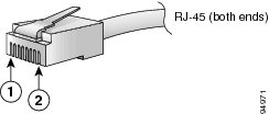
Use a modular, RJ-45, straight-through UTP cable to connect the 10/100 management Ethernet port to external hubs and switches. To connect to a router, use a crossover cable. (See Figure 1-1.)
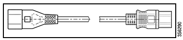
Figure 1-1 RJ-45 Interface Cable Connector
|
|
|
Table 1-4 lists the connector pinouts and signal names for a 10/100BASE-T management port (MDI) cable.
|
|
|
|---|---|
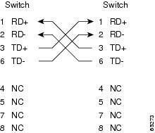
Figure 1-2 shows a schematic of the 10/100BASE-T cable.
Figure 1-2 Twisted-Pair 10/100BASE-T Cable Schematic
Supported Power Cords and Plugs
A separate power cord is provided for each power supply. Standard power cords or jumper power cords are available for connection to a power distribution unit having IEC 60320 C13 outlet receptacles. The jumper power cords, for use in cabinets, are available as an option instead of the standard power cords.
Power Cords
The standard power cords have an IEC C15 connector on the end that plugs into the switch. The optional jumper power cords have an IEC C15 connector on the end that plugs into the switch, and an IEC C14 connector on the end that plugs into an IEC C13 outlet receptacle.
Note![]() Only the standard power cords or jumper power cords provided with the switch are supported.
Only the standard power cords or jumper power cords provided with the switch are supported.
Note![]() If you do not order the optional power cord with the system, you are responsible for selecting the appropriate power cord for the product. Using a non-compatible power cord with this product may result in electrical safety hazard. Orders delivered to Argentina, Brazil, and Japan must have the appropriate power cord ordered with the system.
If you do not order the optional power cord with the system, you are responsible for selecting the appropriate power cord for the product. Using a non-compatible power cord with this product may result in electrical safety hazard. Orders delivered to Argentina, Brazil, and Japan must have the appropriate power cord ordered with the system.
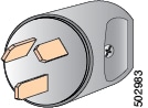
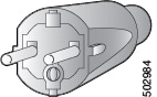
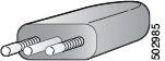
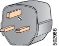
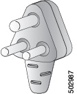
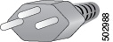
Table 1-5 shows the supported plugs for the Cisco MDS 9100 Series power supplies.
|
|
|
|
|
|
|
|---|---|---|---|---|---|
|
|||||
|
|||||
|
|||||
|
|||||
|
|||||
|
|||||
|
|||||
|
|||||
|
|||||
|
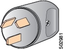
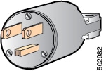
Jumper Power Cord
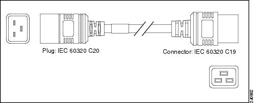
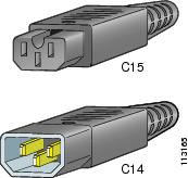
Figure 1-3 shows the C14 and C15 connectors on the optional jumper power cord for the Cisco MDS 9148S Switch. The C15 connector connects into the C14 inlet on the Cisco MDS 9148S Switch power supply, while the C14 connector connects into the C13 receptacle of a power distribution unit for a cabinet.
Figure 1-3 Connectors on Jumper Power Cord for Cisco MDS 9148S Switch
 Feedback