Connecting the Cisco MDS 9148S Switch
The Cisco MDS 9148S switch provides the following types of ports:
- Console port (Interface Module)—An RS-232 port that you can use to create a local management connection.
- MGMT 10/100 Ethernet port (Interface Module)—An Ethernet port that you can use to access and manage the switch by IP address, such as through the CLI or Fabric Manager.
- Fibre Channel ports (Supervisor and Switching Modules)— Fibre Channel ports that you can use to connect to the SAN, or for in-band management.
This chapter describes how to connect the various components of the Cisco MDS 9148S switch, and it includes the following information:
Preparing for Network Connections
When preparing your site for network connections to the Cisco MDS 9148S switch, consider the following for each type of interface:
- Cabling required for each interface type
- Distance limitations for each signal type
- Additional interface equipment needed
Before installing the component, have all additional external equipment and cables available.
Connecting the Console Port
This section describes how to connect the RS-232 console port to a PC. The console port allows you to perform the following functions:
- Configure the switch from the CLI.
- Monitor network statistics and errors.
- Configure SNMP agent parameters.
- Download software updates to the switch or distribute software images residing in flash memory to attached devices.
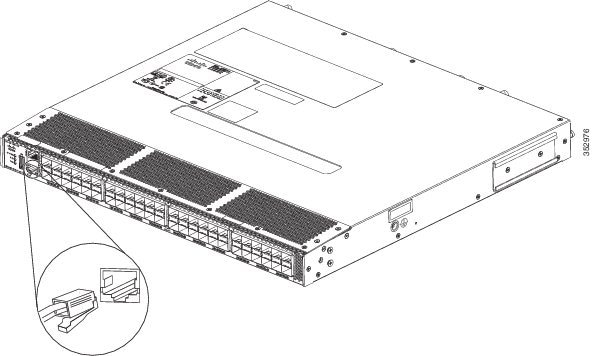
The console port, located on the front panel, is shown in Figure 1-1.
Figure 1-1 Connecting the Console Cable
Connecting the Console Port to a PC
You can connect the console port to a PC serial port for local administrative access to the Cisco MDS 9148S switch.

Note![]() The PC must support VT100 terminal emulation. The terminal emulation software—frequently a PC application such as HyperTerminal Plus—makes communication between the Cisco MDS 9148S switch and your PC possible during setup and configuration.
The PC must support VT100 terminal emulation. The terminal emulation software—frequently a PC application such as HyperTerminal Plus—makes communication between the Cisco MDS 9148S switch and your PC possible during setup and configuration.
To connect the console port to a PC, follow these steps:
Step 1![]() Configure the baud rate and character format of the PC terminal emulation program to match the following management port default characteristics:
Configure the baud rate and character format of the PC terminal emulation program to match the following management port default characteristics:
Step 2![]() Connect the supplied RJ-45 to DB-9 female adapter or RJ-45 to DB-25 female adapter (depending on your PC connection) to the PC serial port.
Connect the supplied RJ-45 to DB-9 female adapter or RJ-45 to DB-25 female adapter (depending on your PC connection) to the PC serial port.
Step 3![]() Connect one end of the supplied console cable (a rollover RJ-45 to RJ-45 cable) to the console port. (See Figure 1-1.) Connect the other end to the RJ-45 to DB-9 (or RJ-45 to DB-25) adapter at the PC serial port.
Connect one end of the supplied console cable (a rollover RJ-45 to RJ-45 cable) to the console port. (See Figure 1-1.) Connect the other end to the RJ-45 to DB-9 (or RJ-45 to DB-25) adapter at the PC serial port.
Connecting a Modem to a Console Port

To connect the console port to a modem before the switch is powered on, follow these steps:
Step 1![]() Connect the supplied console cable (a rollover RJ-45 to RJ-45 cable) to the console port (see Figure 1-1).
Connect the supplied console cable (a rollover RJ-45 to RJ-45 cable) to the console port (see Figure 1-1).
Step 2![]() Connect the other end of the console cable to the supplied RJ-45 to DB-25 adapter.
Connect the other end of the console cable to the supplied RJ-45 to DB-25 adapter.
Step 3![]() Connect the RJ-45-to-DB-25 adapter to the DB-25 port on the modem.
Connect the RJ-45-to-DB-25 adapter to the DB-25 port on the modem.
Step 4![]() Power on the switch. The switch boots automatically, and the following default console port characteristics are applied to the modem connection:
Power on the switch. The switch boots automatically, and the following default console port characteristics are applied to the modem connection:
- 9600 baud
- 8 data bits
- 1 stop bit
- No parity
- Default initialization string (ATE0Q1&D2&C1S0=1\015) if previously configured
Note![]() For instructions on how to change these settings, see the Cisco Fabric Manager Fundamentals Configuration Guide for instructions on how to change these settings.
For instructions on how to change these settings, see the Cisco Fabric Manager Fundamentals Configuration Guide for instructions on how to change these settings.
To connect the console port to a modem after the switch is powered on, follow these steps:
Step 1![]() Ensure that the system has completed booting and the system image is running.
Ensure that the system has completed booting and the system image is running.
Step 2![]() Connect the supplied console cable (a rollover RJ-45 to RJ-45 cable) to the console port (see Figure 1-1).
Connect the supplied console cable (a rollover RJ-45 to RJ-45 cable) to the console port (see Figure 1-1).
Step 3![]() Connect the other end of the console cable to the supplied RJ-45 to DB-25 adapter.
Connect the other end of the console cable to the supplied RJ-45 to DB-25 adapter.
Step 4![]() Connect the RJ-45-to-DB-25 adapter to the DB-25 port on the modem.
Connect the RJ-45-to-DB-25 adapter to the DB-25 port on the modem.
Step 5![]() Initialize and configure the modem as specified in the Cisco Fabric Manager Fundamentals Configuration Guide and the Cisco NX-OS Fundamentals Configuration Guide.
Initialize and configure the modem as specified in the Cisco Fabric Manager Fundamentals Configuration Guide and the Cisco NX-OS Fundamentals Configuration Guide.
Connecting the 10/100/1000 Ethernet Management Port
The autosensing 10/100/1000 Ethernet management port is located on the left side of the front panel (labeled 10/100 MGMT), to the right of the Console port. This port is used for out-of-band management of the Cisco MDS 9148S switch.
Use a modular, RJ-45, straight-through UTP cable to connect the 10/100/1000 management Ethernet port to external hubs and switches. To connect to a router, use a crossover cable.
Connecting to a Fibre Channel Port
The Fibre Channel ports are compatible with LC-type fiber-optic SFP transceivers and cables (see “Removing and Installing Cables into SFP Transceivers” section). You can use these ports to connect to the SAN or for in-band management. For information about configuring the switch for in-band management, see the Cisco Fabric Manager Fundamentals Configuration Guide and the Cisco NX-OS Fundamentals Configuration Guide.
The Cisco MDS 9148S switch supports both Fibre Channel and Gigabit Ethernet protocols for SFP transceivers. Each transceiver must match the transceiver on the other end of the cable, and the cable must not exceed the stipulated cable length for reliable communications. SFP transceivers can be ordered separately or with the Cisco MDS 9148S switch.

Warning![]() Class 1 laser product. Statement 1008
Class 1 laser product. Statement 1008
Warning![]() Invisible laser radiation may be emitted from disconnected fibers or connectors. Do not stare into beams or view directly with optical instruments. Statement 1051
Invisible laser radiation may be emitted from disconnected fibers or connectors. Do not stare into beams or view directly with optical instruments. Statement 1051
This section includes the following information:
- Removing and Installing SFP Transceivers
- Removing and Installing Cables into SFP Transceivers
- Maintaining SFP Transceivers and Fiber-Optic Cables
Removing and Installing SFP Transceivers
We recommend disconnecting cables before installing or removing SFP transceivers to prevent damage to the cable or transceiver.
Note![]() Use only Cisco SFP transceivers on the Cisco MDS 9148S switch. Each Cisco SFP transceiver is encoded with model information that enables the switch to verify that the SFP transceiver meets the requirements for the switch.
Use only Cisco SFP transceivers on the Cisco MDS 9148S switch. Each Cisco SFP transceiver is encoded with model information that enables the switch to verify that the SFP transceiver meets the requirements for the switch.
The Cisco MDS 9148S switch supports SFP transceivers with the following two types of latching devices:
- Mylar tab latch (Figure 1-2)
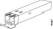
- Bale-clasp latch (Figure 1-3)
Figure 1-2 SFP Transceiver with Mylar Tab Latch
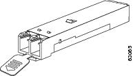
Figure 1-3 SFP Transceiver with Bale-Clasp Latch
Installing an SFP Transceiver
To install an SFP transceiver, follow these steps:
Step 1![]() Attach an ESD-preventive wrist strap and follow its instructions for use.
Attach an ESD-preventive wrist strap and follow its instructions for use.
Step 2![]() Remove the dust cover from the port cage.
Remove the dust cover from the port cage.
Step 3![]() Remove the dust cover from the port end of the transceiver.
Remove the dust cover from the port end of the transceiver.
Step 4![]() Insert the transceiver into the port:
Insert the transceiver into the port:
- If the transceiver has a mylar tab latch, orient the transceiver with the tab on the bottom, and then gently insert the transceiver into the port until it clicks into place.
- If the transceiver has a bale-clasp latch, orient the transceiver with the bale clasp on the bottom, close the bale clasp by pushing it up and over the transceiver, and then gently insert the transceiver into the port until it clicks into place.
Step 5![]() Insert or leave the dust plug in the cable end of the transceiver if a cable is not being installed in the transceiver.
Insert or leave the dust plug in the cable end of the transceiver if a cable is not being installed in the transceiver.
Removing an SFP Transceiver
To remove an SFP transceiver, follow these steps:
Step 1![]() Attach an ESD-preventive wrist strap and follow its instructions for use.
Attach an ESD-preventive wrist strap and follow its instructions for use.
Step 2![]() Perform these steps if cable is installed in the transceiver:
Perform these steps if cable is installed in the transceiver:
a.![]() Record the cable and port connections for later reference.
Record the cable and port connections for later reference.
b.![]() Press the release latch on the cable, grasp the connector near the connection point, and gently pull the connector from the transceiver.
Press the release latch on the cable, grasp the connector near the connection point, and gently pull the connector from the transceiver.
c.![]() Insert a dust plug into the connector on the cable.
Insert a dust plug into the connector on the cable.
d.![]() Insert a dust plug into the cable end of the transceiver.
Insert a dust plug into the cable end of the transceiver.

Tip If the transceiver does not remove easily in the next step, push the transceiver all the way back in and then ensure that the latch is in the correct position before continuing.
Step 3![]() Remove the transceiver from the port:
Remove the transceiver from the port:
- If the transceiver has a mylar tab latch, gently pull the tab straight out (do not twist), and then pull the transceiver out of the port.
- If the transceiver has a bale-clasp latch, open the clasp by pressing it downwards, and then pull the transceiver out of the port.
Step 4![]() Insert a dust cover into the port end of the transceiver and place the transceiver on an antistatic mat or into a static shielding bag if you plan to return it to the factory.
Insert a dust cover into the port end of the transceiver and place the transceiver on an antistatic mat or into a static shielding bag if you plan to return it to the factory.
Step 5![]() Protect the optical cage by inserting a clean cover if another transceiver is not being installed.
Protect the optical cage by inserting a clean cover if another transceiver is not being installed.
Removing and Installing Cables into SFP Transceivers
Installing a Cable into an SFP Transceiver
To install a cable into a transceiver, follow these steps:
Step 1![]() Attach an ESD-preventive wrist strap and follow its instructions for use.
Attach an ESD-preventive wrist strap and follow its instructions for use.
Step 2![]() Remove the dust cover from the connector on the cable.
Remove the dust cover from the connector on the cable.
Step 3![]() Remove the dust cover from the cable end of the transceiver.
Remove the dust cover from the cable end of the transceiver.
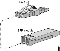
Step 4![]() Align the cable connector with the transceiver and insert the connector into the transceiver until it clicks into place. (See Figure 1-4).
Align the cable connector with the transceiver and insert the connector into the transceiver until it clicks into place. (See Figure 1-4).
Figure 1-4 Connecting the LC-Type Cable to a Fibre Channel Port
For instructions on verifying connectivity, see the Cisco Fabric Manager Fundamentals Configuration Guide and the Cisco NX-OS Fundamentals Configuration Guide.
Removing a Cable from an SFP Transceiver
To remove the cable, follow these steps:
Step 1![]() Attach an ESD-preventive wrist strap and follow its instructions for use.
Attach an ESD-preventive wrist strap and follow its instructions for use.
Step 2![]() Press the release latch on the cable, grasp the connector near the connection point, and gently pull the connector from the transceiver.
Press the release latch on the cable, grasp the connector near the connection point, and gently pull the connector from the transceiver.
Step 3![]() Insert a dust plug into the cable end of the transceiver.
Insert a dust plug into the cable end of the transceiver.
Step 4![]() Insert a dust plug onto the end of the cable.
Insert a dust plug onto the end of the cable.
Maintaining SFP Transceivers and Fiber-Optic Cables
SFP transceivers and fiber-optic cables must be kept clean and dust-free to maintain high signal accuracy and prevent damage to the connectors. Attenuation (loss of light) is increased by contamination, and it should be kept below 0.35 dB.
Follow these maintenance guidelines:
- SFP transceivers are static sensitive. To prevent ESD damage, wear an ESD-preventive wrist strap that is connected to the chassis.
- Do not remove and insert a transceiver more often than necessary. Repeated removals and insertions can shorten its useful life.
- Keep all optical connections covered when not in use. If they become dusty, clean before using to prevent dust from scratching the fiber-optic cable ends.
- Do not touch ends of connectors. This prevents fingerprints and other contamination of the connectors.
- Clean regularly; the required frequency of cleaning depends upon the environment. In addition, clean connectors if they are exposed to dust or accidentally touched. Both wet and dry cleaning techniques can be effective; refer to your site’s fibre-optic connection cleaning procedures.
- Inspect routinely for dust and damage. If damage is suspected, clean and then inspect fiber ends under a microscope to determine if damage has occurred.
 Feedback