Installing the Cisco MDS 9148S Switch
This chapter describes how to install the MDS 9148S switch and its components, and it includes the following information:
- Preinstallation
- Front-Facing Installation
- Installing the Switch in a Cabinet with Insufficient Front Clearance
- Grounding the Switch
- Grounding the Switch
- Starting Up the Switch
- Removing and Installing Components

Note![]() Before you install, operate, or service the system, read the Regulatory Compliance and Safety Information for the Cisco MDS 9000 Family for important safety information.
Before you install, operate, or service the system, read the Regulatory Compliance and Safety Information for the Cisco MDS 9000 Family for important safety information.

Warning![]() IMPORTANT SAFETY INSTRUCTIONS
IMPORTANT SAFETY INSTRUCTIONS
This warning symbol means danger. You are in a situation that could cause bodily injury. Before you work on any equipment, be aware of the hazards involved with electrical circuitry and be familiar with standard practices for preventing accidents. Use the statement number provided at the end of each warning to locate its translation in the translated safety warnings that accompanied this device. Statement 1071
SAVE THESE INSTRUCTIONS
Warning![]() This unit is intended for installation in restricted access areas. A restricted access area can be accessed only through the use of a special tool, lock and key, or other means of security. Statement 1017
This unit is intended for installation in restricted access areas. A restricted access area can be accessed only through the use of a special tool, lock and key, or other means of security. Statement 1017
Warning![]() Only trained and qualified personnel should be allowed to install, replace, or service this equipment. Statement 1030
Only trained and qualified personnel should be allowed to install, replace, or service this equipment. Statement 1030
Note![]() Each new switch requires a license; see the Cisco MDS 9000 Family NX-OS Licensing Guide for instructions on installing a license.
Each new switch requires a license; see the Cisco MDS 9000 Family NX-OS Licensing Guide for instructions on installing a license.
Preinstallation
This section includes the following information:
Installation Options
The MDS 9148S Switch can be installed using the following methods:
–![]() The rack-mount kit shipped with the switch
The rack-mount kit shipped with the switch
–![]() The Telco and EIA Shelf Bracket Kit (an optional kit, purchased separately) in addition to the rack-mount kit shipped with the switch
The Telco and EIA Shelf Bracket Kit (an optional kit, purchased separately) in addition to the rack-mount kit shipped with the switch
–![]() The Telco and EIA Shelf Bracket Kit (an optional kit, purchased separately) in addition to the front brackets shipped with the switch
The Telco and EIA Shelf Bracket Kit (an optional kit, purchased separately) in addition to the front brackets shipped with the switch
For instructions on installing the switch using the rack-mount kit shipped with the switch, see the “Front-Facing Installation” section.
For instructions on installing the switch using the optional, separately purchased Telco and EIA Shelf Bracket Kit, see the “Cisco MDS 9000 Family Telco and EIA Shelf Bracket” section.
Note![]() The Telco and EIA Shelf Bracket Kit is optional and is not provided with the switch. To order the kit, contact your switch provider.
The Telco and EIA Shelf Bracket Kit is optional and is not provided with the switch. To order the kit, contact your switch provider.
Installation Guidelines
Follow these guidelines when installing the Cisco MDS 9148S Switch:
- Plan your site configuration and prepare the site before installing the switch. The recommended site planning tasks are listed in Appendix 1, “Site Planning and Maintenance Records.”
- Ensure there is adequate space around the switch to allow for servicing the switch and for adequate airflow (airflow requirements are listed in Appendix 1, “Technical Specifications” ).
- Ensure the air-conditioning meets the heat dissipation requirements listed in Appendix 1, “Technical Specifications.”
- Ensure the cabinet or rack meets the requirements listed in Appendix 1, “Cabinet and Rack Installation.”
Note![]() If the front cabinet mounting rails are not offset from the front door or bezel panel by a minimum of 3 inch (7.6 cm), and a minimum of 5 inch. (12.7 cm) if cable management brackets are installed on the front of the chassis, the chassis should be mounted rear-facing to ensure the minimum bend radius for fiber-optic cables. See the “Installing the Switch in a Cabinet with Insufficient Front Clearance” section.
If the front cabinet mounting rails are not offset from the front door or bezel panel by a minimum of 3 inch (7.6 cm), and a minimum of 5 inch. (12.7 cm) if cable management brackets are installed on the front of the chassis, the chassis should be mounted rear-facing to ensure the minimum bend radius for fiber-optic cables. See the “Installing the Switch in a Cabinet with Insufficient Front Clearance” section.
Note![]() Jumper power cords are available for use in a cabinet. For more information, see the “Jumper Power Cord”.
Jumper power cords are available for use in a cabinet. For more information, see the “Jumper Power Cord”.
- Ensure the chassis is adequately grounded. If the switch is not mounted in a grounded rack, we recommend connecting both the system ground on the chassis and the power supply ground to an earth ground.
- Ensure the site power meets the power requirements listed in Appendix 1, “Technical Specifications.” If available, you can use an uninterrupted power supply (UPS) to protect against power failures.

For North America, the 300-W power supplies require a 20-A circuit. If you are using a 200- or 240-VAC power source in North America, the circuit must be protected by a two-pole circuit breaker.
- As you install and configure the switch, record the information listed in the “Site Planning and Maintenance Records” section.
- Use the following screw torques when installing the switch:
Required Equipment
Gather the following tools before beginning the installation:
- Number 1 Phillips screwdriver with torque capability
- 3/16-in. flat-blade screwdriver
- Tape measure and level
- ESD wrist strap or other grounding device
- Antistatic mat or antistatic foam
The following additional items (not found in the accessory kit) are required to ground the chassis:
Unpacking and Inspecting the Switch

Tip![]() Keep the shipping container in case the chassis requires shipping in the future.
Keep the shipping container in case the chassis requires shipping in the future.
Note![]() If you purchased Cisco support through a Cisco reseller, contact the reseller directly. If you purchased support directly from Cisco, contact Cisco Technical Support at this URL: http://www.cisco.com/en/US/support/tsd_cisco_worldwide_contacts.html
If you purchased Cisco support through a Cisco reseller, contact the reseller directly. If you purchased support directly from Cisco, contact Cisco Technical Support at this URL: http://www.cisco.com/en/US/support/tsd_cisco_worldwide_contacts.html
Note![]() The switch is thoroughly inspected before shipment. If any damage occurred during transportation or any items are missing, contact your customer representative immediately.
The switch is thoroughly inspected before shipment. If any damage occurred during transportation or any items are missing, contact your customer representative immediately.
To inspect the shipment, follow these steps:
Step 1![]() Compare the shipment to the equipment list provided by your customer service representative and verify that you have received all items, including the following:
Compare the shipment to the equipment list provided by your customer service representative and verify that you have received all items, including the following:
Step 2![]() Check for damage and report any discrepancies or damage to your customer service representative. Have the following information ready:
Check for damage and report any discrepancies or damage to your customer service representative. Have the following information ready:
Front-Facing Installation
To install the switch in a cabinet or rack using the rack-mount kit provided with the switch, follow these steps:
Step 1![]() Install the front rack-mount bracket as follows:
Install the front rack-mount bracket as follows:
a.![]() Position one of the front rack-mount brackets against the side of the switch and align the screw holes. Then attach the bracket to the switch with the three M4 screws originally provided with the bracket.
Position one of the front rack-mount brackets against the side of the switch and align the screw holes. Then attach the bracket to the switch with the three M4 screws originally provided with the bracket.
b.![]() Repeat with the other front rack-mount bracket on the other side of the switch.
Repeat with the other front rack-mount bracket on the other side of the switch.
Step 2![]() Install the C brackets as follows:
Install the C brackets as follows:
Note![]() Two C brackets are shipped preinstalled on the switch, using three M3 screws per bracket. This installation step is only necessary if the C brackets were removed.
Two C brackets are shipped preinstalled on the switch, using three M3 screws per bracket. This installation step is only necessary if the C brackets were removed.
a.![]() Position one of the C brackets against the side of the switch and align the screw holes. Attach the bracket to the switch with the three M3 screws originally provided with the bracket.
Position one of the C brackets against the side of the switch and align the screw holes. Attach the bracket to the switch with the three M3 screws originally provided with the bracket.
b.![]() Repeat with the other C bracket on the other side of the switch.
Repeat with the other C bracket on the other side of the switch.
Step 3![]() Install the slider rails in the rack. Position one of the slider rails against the rack mounting rails and align the screw holes as shown in Figure 2-1.
Install the slider rails in the rack. Position one of the slider rails against the rack mounting rails and align the screw holes as shown in Figure 2-1.
Step 4![]() Attach the slider rail using two 12-24 screws or two 10-32 screws, depending on the rack rail thread type. For racks with square holes, insert the 12-24 cage nuts in position behind the mounting holes in the slider rails.
Attach the slider rail using two 12-24 screws or two 10-32 screws, depending on the rack rail thread type. For racks with square holes, insert the 12-24 cage nuts in position behind the mounting holes in the slider rails.
a.![]() Repeat with the other slider rail on the other side of the rack.
Repeat with the other slider rail on the other side of the rack.
b.![]() Use the tape measure and level to verify that the rails are horizontal and at the same height.
Use the tape measure and level to verify that the rails are horizontal and at the same height.
Figure 2-1 Installing the Slider Rails
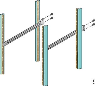
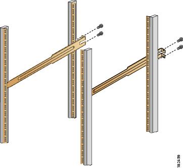
Figure 2-2 Installing the Notched Slider Rails
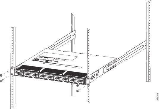
Step 5![]() Insert the switch into the rack:
Insert the switch into the rack:
a.![]() By using both hands, position the switch with the back of the switch between the front rack-mounting rails as shown in Figure 2-3.
By using both hands, position the switch with the back of the switch between the front rack-mounting rails as shown in Figure 2-3.
b.![]() Align the two C brackets on either side of the switch with the slider rails installed in the rack. Slide the C brackets onto the slider rails, and then gently slide the switch all the way into the rack. If the switch does not slide easily, try realigning the C brackets on the slider rails.
Align the two C brackets on either side of the switch with the slider rails installed in the rack. Slide the C brackets onto the slider rails, and then gently slide the switch all the way into the rack. If the switch does not slide easily, try realigning the C brackets on the slider rails.
Step 6![]() Stabilize the switch in the rack by attaching the front rack-mount brackets to the front rack-mounting rails:
Stabilize the switch in the rack by attaching the front rack-mount brackets to the front rack-mounting rails:
a.![]() Insert two screws (12-24 or 10-32, depending on rack type) and through the cage nuts and the holes in one of the front rack-mount brackets and into the threaded holes in the rack-mounting rail.
Insert two screws (12-24 or 10-32, depending on rack type) and through the cage nuts and the holes in one of the front rack-mount brackets and into the threaded holes in the rack-mounting rail.
b.![]() Repeat for the front rack-mount bracket on the other side of the switch.
Repeat for the front rack-mount bracket on the other side of the switch.
If you are installing the optional cable guides, place the cable guides in front of the front rack-mount brackets, and then pass the screws through the cable guides, front rack-mount brackets, and mounting rail. You can install one or both cable guides; if installing a single cable guide, it can be installed on either side.
Figure 2-3 Attaching the Switch to the Rack
Installing the Switch in a Cabinet with Insufficient Front Clearance
This section describes how to use the rack-mount kit provided with the switch to install the Cisco MDS 9148S switch into a cabinet with insufficient front-facing clearance. The Cisco MDS 9148S switch is installed rear-facing to provide adequate clearance for the fiber-optic cables. This cabinet meets the requirements described in Appendix 1, “Cabinet and Rack Installation,” except the cabinet has less than three-inch clearance between the inside of the front door or bezel panel and the front cabinet mounting rails. This rear-facing installation is necessary to ensure that the minimum bend radius for the fiber-optic cables is maintained. In these cabinets, the Cisco MDS 9148S switch is mounted backwards, with the fiber-optic cables facing toward the rear of the cabinet and the power supplies facing the front of the cabinet.
The rack-mount kit provided with the switch contains the items listed in Table 2-1 .
Table 2-1 Table 2-1 Cisco MDS 9148S Fabric Switch Rack-Mount Kit
|
|
|
|---|---|
Installing Front Rack-Mount Brackets for Cabinets with 26 Inches or Greater of Rail Spacings
The front rack-mount brackets for the Cisco MDS 9148S switch must be installed onto the switch prior to installing the switch into the cabinet. Follow these steps for cabinets with front-mounting rail to rear-mounting rail spacings greater or equal to 26 inches:
Step 1![]() Install the front rack-mount brackets as follows:
Install the front rack-mount brackets as follows:
a.![]() Position one of the front rack-mount brackets against the side of the switch and align the screw holes as shown in Figure 2-4. Then attach the bracket to the switch with the three M4 screws originally provided with the bracket.
Position one of the front rack-mount brackets against the side of the switch and align the screw holes as shown in Figure 2-4. Then attach the bracket to the switch with the three M4 screws originally provided with the bracket.
b.![]() Repeat with the other front-rack mount bracket on the other side of the switch.
Repeat with the other front-rack mount bracket on the other side of the switch.
Step 2![]() Install the C brackets as follows:
Install the C brackets as follows:
Note![]() Two C brackets are shipped preinstalled on the switch, using three M3 screws per bracket. This installation step is only necessary if the C brackets were removed.
Two C brackets are shipped preinstalled on the switch, using three M3 screws per bracket. This installation step is only necessary if the C brackets were removed.
a.![]() Position one of the C brackets against the side of the switch and align the screw holes. Attach the bracket to the switch with the three M3 screws originally provided with the bracket.
Position one of the C brackets against the side of the switch and align the screw holes. Attach the bracket to the switch with the three M3 screws originally provided with the bracket.
b.![]() Repeat with the other C bracket on the other side of the switch.
Repeat with the other C bracket on the other side of the switch.
Installing Front Rack-Mount Brackets for Cabinets with Less Than 26 Inches of Rail Spacings
The front rack-mount brackets for the Cisco MDS 9148S switch must be installed onto the switch prior to installing the switch into the cabinet. To install brackets for cabinets with front-mounting rail to rear-mounting rail spacings less than 26 inches that need to be mounted backwards to maintain adequate fiber-optic clearances, follow these steps:
Step 1![]() Install the front-rack mount brackets for cabinets with rail-to-rail spacings less than 26 inches as follows:
Install the front-rack mount brackets for cabinets with rail-to-rail spacings less than 26 inches as follows:
a.![]() Position one of the front rack-mount brackets against the side of the switch and align the screw holes. Then attach the bracket to the switch with two of the three M4 screws originally provided with the bracket.
Position one of the front rack-mount brackets against the side of the switch and align the screw holes. Then attach the bracket to the switch with two of the three M4 screws originally provided with the bracket.
b.![]() Repeat with the other front rack-mount bracket on the other side of the switch.
Repeat with the other front rack-mount bracket on the other side of the switch.
Note![]() The front rack-mount bracket does not align with all three holes in the Cisco MDS 9148S switch in this configuration. The two screws are adequate to hold the weight of the Cisco MDS 9148S switch.
The front rack-mount bracket does not align with all three holes in the Cisco MDS 9148S switch in this configuration. The two screws are adequate to hold the weight of the Cisco MDS 9148S switch.
Step 2![]() Install the C brackets as follows:
Install the C brackets as follows:
Note![]() Two C brackets are shipped preinstalled on the switch, using three M3 screws per bracket. This installation step is only necessary if the C brackets were removed.
Two C brackets are shipped preinstalled on the switch, using three M3 screws per bracket. This installation step is only necessary if the C brackets were removed.
a.![]() Position one of the C brackets against the side of the switch and align the screw holes. Then attach the bracket to the switch with the three M3 screws originally provided with the bracket.
Position one of the C brackets against the side of the switch and align the screw holes. Then attach the bracket to the switch with the three M3 screws originally provided with the bracket.
b.![]() Repeat with the other C bracket on the other side of the switch.
Repeat with the other C bracket on the other side of the switch.
Installing Cisco MDS 9148S Switch Rear-Facing into Cabinet
To install a Cisco MDS 9148S switch rear-facing into a cabinet using the rack-mount kit provided with the switch (for cabinets with insufficient front-facing clearance), follow these steps:
Step 1![]() Install the notched slider rails in the rack:
Install the notched slider rails in the rack:
a.![]() Route the power cord through the open cutout at the end of one of the slider rails, and then let the cord dangle while you proceed with the next steps.
Route the power cord through the open cutout at the end of one of the slider rails, and then let the cord dangle while you proceed with the next steps.
b.![]() Position one of the slider rails against the front rack-mounting rails and align the screw holes. Attach them using two 12-24 screws or two 10-32 screws, depending on the rack rail thread type. For racks with square holes, first install the 12-24 cage nuts.
Position one of the slider rails against the front rack-mounting rails and align the screw holes. Attach them using two 12-24 screws or two 10-32 screws, depending on the rack rail thread type. For racks with square holes, first install the 12-24 cage nuts.
c.![]() Repeat with the other slider rail on the other front side of the rack.
Repeat with the other slider rail on the other front side of the rack.
d.![]() Use the tape measure and level to verify that the rails are horizontal and at the same height.
Use the tape measure and level to verify that the rails are horizontal and at the same height.
Step 2![]() Insert the switch into the rack:
Insert the switch into the rack:
a.![]() Using both hands, position the switch with the back of the switch between the rear rack-mounting rails.
Using both hands, position the switch with the back of the switch between the rear rack-mounting rails.
b.![]() Align the two C brackets on either side of the switch with the slider rails installed in the rack. Slide the C brackets onto the slider rails and then gently slide the switch all the way into the rack. If the switch does not slide easily, try realigning the C brackets on the slider rails.
Align the two C brackets on either side of the switch with the slider rails installed in the rack. Slide the C brackets onto the slider rails and then gently slide the switch all the way into the rack. If the switch does not slide easily, try realigning the C brackets on the slider rails.
Step 3![]() Connect the power cord that you previously routed through the open cutout of the slider rail to the switch. Limit the length of the power cord between the back of the chassis and the rail opening.
Connect the power cord that you previously routed through the open cutout of the slider rail to the switch. Limit the length of the power cord between the back of the chassis and the rail opening.
Note![]() If you failed to route the power cord through the open cutout of the slider rail as directed in Step 1, remove the switch and rails and remount the rails using the correct method. Do not connect the power cord by routing it over the top of the slider rail. This type of installation is hazardous.
If you failed to route the power cord through the open cutout of the slider rail as directed in Step 1, remove the switch and rails and remount the rails using the correct method. Do not connect the power cord by routing it over the top of the slider rail. This type of installation is hazardous.
Step 4![]() Stabilize the switch in the rack by attaching the front rack-mount brackets to the rear rack-mounting rails:
Stabilize the switch in the rack by attaching the front rack-mount brackets to the rear rack-mounting rails:
a.![]() Insert two screws (12-24 or 10-32, depending on rack type) through the holes in one of the front rack-mount brackets and into the threaded holes in the back rack-mounting rail (see Figure 2-4). For racks with square holes, first install the 12-24 cage nuts.
Insert two screws (12-24 or 10-32, depending on rack type) through the holes in one of the front rack-mount brackets and into the threaded holes in the back rack-mounting rail (see Figure 2-4). For racks with square holes, first install the 12-24 cage nuts.
Figure 2-4 Attaching the Cisco MDS 9148S Switch (Rear-Facing) to the Cabinet
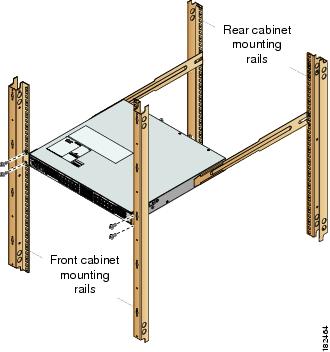
b.![]() Repeat for the front rack-mount bracket on the other side of the switch.
Repeat for the front rack-mount bracket on the other side of the switch.
Tip![]() If the chassis exceeds the 1-RU space on the low side of the rack, you may have difficulty installing other equipment. In this situation, loosen the screws on the front and back rails of the chassis and raise it to the top of the RU space by pushing the chassis up until it cannot go any further. Then retighten the screws while keeping the chassis in the elevated position.
If the chassis exceeds the 1-RU space on the low side of the rack, you may have difficulty installing other equipment. In this situation, loosen the screws on the front and back rails of the chassis and raise it to the top of the RU space by pushing the chassis up until it cannot go any further. Then retighten the screws while keeping the chassis in the elevated position.
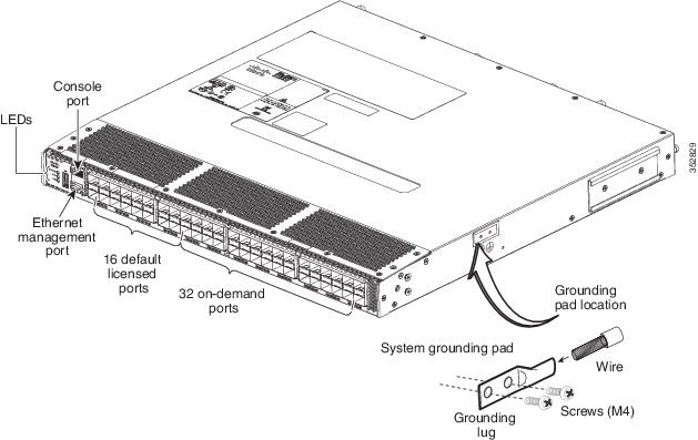
Grounding the Switch
A grounding pad with two threaded M4 holes is provided on the chassis for attaching a grounding lug. Figure 2-5 shows the system ground location on the Cisco MDS 9148S switch.
Figure 2-5 Location of Switch Ground on the Cisco MDS 9148S Switch
Warning![]() When installing or replacing the unit, the ground connection must always be made first and disconnected last. Statement 1046
When installing or replacing the unit, the ground connection must always be made first and disconnected last. Statement 1046
Note![]() If the rack is less than 25-in. (635 mm) deep, the slider rails will cover the grounding hole. Therefore, the rack must either be grounded or at least 25-in. (635 mm) deep.
If the rack is less than 25-in. (635 mm) deep, the slider rails will cover the grounding hole. Therefore, the rack must either be grounded or at least 25-in. (635 mm) deep.
Note![]() The grounding lug must be NRTL listed and compatible with copper conductors. Only copper conductors (wires) must be used and the copper conductor must comply with National Electrical Code (NEC) for ampacity.
The grounding lug must be NRTL listed and compatible with copper conductors. Only copper conductors (wires) must be used and the copper conductor must comply with National Electrical Code (NEC) for ampacity.
Note![]() Customers who require compliance to GR-1089-CORE bonding and grounding requirements, must use the ground conductor.
Customers who require compliance to GR-1089-CORE bonding and grounding requirements, must use the ground conductor.
To attach the grounding lug and cable to the chassis, follow these steps:
Step 1![]() Use a wire-stripping tool to remove approximately 0.75 in. (19 mm) of the covering from the end of the grounding cable.
Use a wire-stripping tool to remove approximately 0.75 in. (19 mm) of the covering from the end of the grounding cable.
Step 2![]() Insert the stripped end of grounding cable into the open end of the grounding lug.
Insert the stripped end of grounding cable into the open end of the grounding lug.
Step 3![]() Use the crimping tool to secure the grounding cable in the grounding lug.
Use the crimping tool to secure the grounding cable in the grounding lug.
Step 4![]() Remove the adhesive label from the grounding pad on the chassis.
Remove the adhesive label from the grounding pad on the chassis.
Step 5![]() Place the grounding lug against the grounding pad so that there is solid metal-to-metal contact, and insert the two M4 screws with washers through the holes in the grounding lug and into the grounding pad.
Place the grounding lug against the grounding pad so that there is solid metal-to-metal contact, and insert the two M4 screws with washers through the holes in the grounding lug and into the grounding pad.
Step 6![]() Ensure that the lug and cable do not interfere with other equipment.
Ensure that the lug and cable do not interfere with other equipment.
Step 7![]() Prepare the other end of the grounding cable and connect it to an appropriate grounding point in your site to ensure adequate earth ground.
Prepare the other end of the grounding cable and connect it to an appropriate grounding point in your site to ensure adequate earth ground.
Starting Up the Switch
This section provides instructions for powering up the switch and verifying component installation.
Note![]() Do not connect the MGMT 10/100/1000 Ethernet port to the LAN until the initial switch configuration has been performed. For instructions on connecting to this port, see the “Connecting the Console Port” section.
Do not connect the MGMT 10/100/1000 Ethernet port to the LAN until the initial switch configuration has been performed. For instructions on connecting to this port, see the “Connecting the Console Port” section.
To power up the switch and verify hardware operation, follow these steps:
Step 1![]() Verify that both power supplies and fan modules are installed and tighten any loose captive screws.
Verify that both power supplies and fan modules are installed and tighten any loose captive screws.
Step 2![]() Verify that the power switches on both power supplies are off. Then plug the power cables into the power supplies and arrange the cables so that they cannot be accidentally pulled out.
Verify that the power switches on both power supplies are off. Then plug the power cables into the power supplies and arrange the cables so that they cannot be accidentally pulled out.
Note![]() Depending on the outlet receptacle on your power distribution unit, you may need the optional jumper power cord to connect the Cisco MDS 9148S switch to your outlet receptacle. See the “Jumper Power Cord”.
Depending on the outlet receptacle on your power distribution unit, you may need the optional jumper power cord to connect the Cisco MDS 9148S switch to your outlet receptacle. See the “Jumper Power Cord”.
Step 3![]() Connect the other end of the power cables to an AC power source.
Connect the other end of the power cables to an AC power source.
Step 4![]() Ensure that the switch is adequately grounded as described in the “Installing the Switch in a Cabinet with Insufficient Front Clearance” section, and that the power cables are connected to outlets that have the required AC power voltages (provided in the “Installing the Switch in a Cabinet with Insufficient Front Clearance” section).
Ensure that the switch is adequately grounded as described in the “Installing the Switch in a Cabinet with Insufficient Front Clearance” section, and that the power cables are connected to outlets that have the required AC power voltages (provided in the “Installing the Switch in a Cabinet with Insufficient Front Clearance” section).
Step 5![]() Flip the power switches on the power supplies to the on (|) position. The switch boots automatically.
Flip the power switches on the power supplies to the on (|) position. The switch boots automatically.
Step 6![]() Listen for the fans; they should begin operating as soon as the switch is powered on.
Listen for the fans; they should begin operating as soon as the switch is powered on.
Step 7![]() Verify that the LED behavior is as follows when the switch has finished booting:
Verify that the LED behavior is as follows when the switch has finished booting:
- Fan status LED is green.
- Each power supply LED is green.
- The Switch status LED is green. If this LED is orange or red, then one or more environmental monitors is reporting a problem.
- The Ethernet port Link LEDs should not be on unless the cable is connected.
Note![]() The LEDs for the Fibre Channel ports remain orange until the ports are enabled, and the LED for the MGMT 10/100/1000 Ethernet port remains off until the port is connected.
The LEDs for the Fibre Channel ports remain orange until the ports are enabled, and the LED for the MGMT 10/100/1000 Ethernet port remains off until the port is connected.
If any LEDs other than the Fibre Channel port LEDs are orange or red after the initial boot processes are complete, see the Cisco MDS 9000 Family Troubleshooting Guide.
Step 8![]() Try removing and reinstalling a component that is not operating properly. If it still does not operate correctly, contact your customer service representative for a replacement.
Try removing and reinstalling a component that is not operating properly. If it still does not operate correctly, contact your customer service representative for a replacement.
Note![]() If you purchased Cisco support through a Cisco reseller, contact the reseller directly. If you purchased support directly from Cisco, contact Cisco Technical Support at this URL: http://www.cisco.com/en/US/support/tsd_cisco_worldwide_contacts.html
If you purchased Cisco support through a Cisco reseller, contact the reseller directly. If you purchased support directly from Cisco, contact Cisco Technical Support at this URL: http://www.cisco.com/en/US/support/tsd_cisco_worldwide_contacts.html
Step 9![]() Verify that the system software has booted and the switch has initialized without error messages. If any problems occur, see the Cisco MDS 9000 Family Troubleshooting Guide or the Cisco MDS 9000 Family System Messages Guide. If you cannot resolve an issue, contact your customer service representative.
Verify that the system software has booted and the switch has initialized without error messages. If any problems occur, see the Cisco MDS 9000 Family Troubleshooting Guide or the Cisco MDS 9000 Family System Messages Guide. If you cannot resolve an issue, contact your customer service representative.
Step 10![]() Complete the worksheets provided in Appendix 1, “Site Planning and Maintenance Records” for future reference.
Complete the worksheets provided in Appendix 1, “Site Planning and Maintenance Records” for future reference.
Note![]() A setup utility automatically launches the first time you access the switch and guides you through the basic configuration. For instructions about how to configure the switch and check module connectivity, see the Cisco Fabric Manager Fundamentals Configuration Guide.
A setup utility automatically launches the first time you access the switch and guides you through the basic configuration. For instructions about how to configure the switch and check module connectivity, see the Cisco Fabric Manager Fundamentals Configuration Guide.
Removing and Installing Components
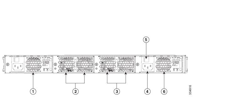
The Cisco MDS 9148S switch is shipped with two field-replaceable power supplies. Each power supply includes a fixed fan. The Cisco MDS 9148S switch has two field-replaceable fan modules.
This section provides the following information:
Warning![]() Hazardous voltage or energy is present on the backplane when the system is operating. Use caution when servicing. Statement 1034
Hazardous voltage or energy is present on the backplane when the system is operating. Use caution when servicing. Statement 1034
Note![]() The Cisco MDS 9148S Switch is only supported for operation with both power supplies and both fan modules installed, and with all fans working.
The Cisco MDS 9148S Switch is only supported for operation with both power supplies and both fan modules installed, and with all fans working.
With two power supplies installed, if one power supply fails, the system can continue to function normally on a single healthy power supply. However, the failed power supply should be replaced as soon as possible to provide redundancy.
The fan modules are required to ensure proper cooling of the switches.
Figure 2-6 Rear View of the Cisco MDS 9148S Switch
Removing and Installing AC Power Supplies
This section provides instructions for removing and installing the AC power supplies for the Cisco MDS 9148S switch.
Removing Power Supplies
To remove a AC power supply, follow these steps:
Step 1![]() Turn the power switch to the off (0) position on the power supply that you are removing.
Turn the power switch to the off (0) position on the power supply that you are removing.
Step 2![]() Disconnect the power cord from the power source.
Disconnect the power cord from the power source.
Step 3![]() Loosen the captive screw.
Loosen the captive screw.
Step 4![]() Grasp the power supply handle and slide the power supply out of the switch.
Grasp the power supply handle and slide the power supply out of the switch.
Installing Power Supplies
To install the dual 300-W AC-input power supplies, follow these steps:
Step 1![]() Ensure that the system (earth) ground connection has been made.
Ensure that the system (earth) ground connection has been made.
Step 2![]() Make sure the power cord is disconnected before installing the power supply.
Make sure the power cord is disconnected before installing the power supply.
Step 3![]() Verify that the power switch is in the off (0) position on the power supply that you are installing.
Verify that the power switch is in the off (0) position on the power supply that you are installing.
Step 4![]() Slide the power supply into the power supply bay. Make sure that the power supply is fully seated in the bay.
Slide the power supply into the power supply bay. Make sure that the power supply is fully seated in the bay.
Step 5![]() Tighten the power supply captive screw.
Tighten the power supply captive screw.
Step 6![]() Plug the power cord into the power supply.
Plug the power cord into the power supply.
Step 7![]() Connect the other end of the power cord to an AC-input power source.
Connect the other end of the power cord to an AC-input power source.
Note![]() Depending on the outlet receptacle on your power distribution unit, you may need the optional jumper power cord to connect the Cisco MDS 9148S switch to your outlet receptacle. See the “Jumper Power Cord”.
Depending on the outlet receptacle on your power distribution unit, you may need the optional jumper power cord to connect the Cisco MDS 9148S switch to your outlet receptacle. See the “Jumper Power Cord”.
Step 8![]() Turn the power switch to the on (|) position on the power supply.
Turn the power switch to the on (|) position on the power supply.
Step 9![]() Verify power supply operation by checking that the power supply (P/S) LED in the front panel is green.
Verify power supply operation by checking that the power supply (P/S) LED in the front panel is green.
If the LED is not green, see the Cisco MDS 9000 Family Troubleshooting Guide.
Removing and Installing Fan Modules
This section provides instructions for removing and installing the fan modules for the Cisco MDS 9148S switch.
Removing a Fan Module on the Cisco MDS 9148S Switch
The fan module is designed to be removed and replaced while the system is operating without presenting an electrical hazard or damaging the system.
Warning![]() When removing the fan tray, keep your hands and fingers away from the spinning fan blades. Let the fan blades completely stop before you remove the fan tray. Statement 258
When removing the fan tray, keep your hands and fingers away from the spinning fan blades. Let the fan blades completely stop before you remove the fan tray. Statement 258
To remove the existing fan module, follow these steps:
Step 1![]() Locate the fan module in the back of the switch.
Locate the fan module in the back of the switch.
Step 2![]() Slide the seating tabs toward the center of the fan module.
Slide the seating tabs toward the center of the fan module.
Step 3![]() Grasp the fan module handle and pull it outward.
Grasp the fan module handle and pull it outward.
Step 4![]() Pull the fan module out of the switch and put it in a safe place.
Pull the fan module out of the switch and put it in a safe place.
Installing a Fan Module
To install a new fan module, follow these steps:
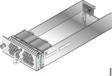
Step 1![]() Position the fan module with the LED oriented away from the back of the switch. Figure 2-7 shows the fan module for the Cisco MDS 9148S switch.
Position the fan module with the LED oriented away from the back of the switch. Figure 2-7 shows the fan module for the Cisco MDS 9148S switch.
Step 2![]() Slide the fan module into the switch until it clicks into place.
Slide the fan module into the switch until it clicks into place.
Figure 2-7 shows the Cisco MDS 9148S fan module.
Figure 2-7 Cisco MDS 9148S Fan Module
Verifying the Fan Module
To verify that the new fan module is installed correctly, follow these steps:
Step 1![]() Listen for the fans; you should immediately hear them operating. If you do not hear them, ensure that the fan module is inserted completely in the switch and the faceplate is flush with the switch back panel.
Listen for the fans; you should immediately hear them operating. If you do not hear them, ensure that the fan module is inserted completely in the switch and the faceplate is flush with the switch back panel.
Step 2![]() Verify that the fan module LED is green. If the LED is orange, then one fan has failed in this fan module; if the LED is red, then both fans have failed in this fan module.
Verify that the fan module LED is green. If the LED is orange, then one fan has failed in this fan module; if the LED is red, then both fans have failed in this fan module.
Step 3![]() Contact your customer service representative for assistance if, after several attempts, the fans do not operate or you experience trouble with the installation.
Contact your customer service representative for assistance if, after several attempts, the fans do not operate or you experience trouble with the installation.
Note![]() Verify that the transceiver and cable type both have LC connectors and are the required type for longwave or shortwave transmission and the required distances. The transceiver label generally lists the model and wavelength.
Verify that the transceiver and cable type both have LC connectors and are the required type for longwave or shortwave transmission and the required distances. The transceiver label generally lists the model and wavelength.
Note![]() If you purchased this product through a Cisco reseller, contact the reseller directly for technical support. If you purchased this product directly from Cisco, contact Cisco Technical Support at this URL: http://www.cisco.com/en/US/support/tsd_cisco_worldwide_contacts.html
If you purchased this product through a Cisco reseller, contact the reseller directly for technical support. If you purchased this product directly from Cisco, contact Cisco Technical Support at this URL: http://www.cisco.com/en/US/support/tsd_cisco_worldwide_contacts.html
 Feedback