Cabinet and Rack Installation
Cabinet and Rack Requirements
This section provides the Cisco MDS 9000 Family requirements for the following types of cabinets and racks, assuming an external ambient air temperature range of 0 to 40°C:
- Standard perforated cabinets
- Solid-walled cabinets with a roof fan tray (bottom to top cooling)
- Standard open racks
- Telco racks

Note![]() If you are selecting an enclosed cabinet, we recommend one of the thermally validated types listed above: standard perforated or solid-walled with a fan tray.
If you are selecting an enclosed cabinet, we recommend one of the thermally validated types listed above: standard perforated or solid-walled with a fan tray.
General Requirements for Cabinets and Racks
The cabinet or rack must be one of the following rack types:
- Standard 19-in. four-post EIA cabinet or rack, with mounting rails that conform to English universal hole spacing per section 1 of ANSI/EIA-310-D-1992. See the “Requirements Specific to Perforated Cabinets” section and “Requirements Specific to Solid-Walled Cabinets” section.
- Standard two-post telco rack, with mounting rails that conform to English universal hole spacing per section 1 of ANSI/EIA-310-D-1992. See the “Requirements Specific to Telco Racks” section.
The cabinet or rack must also meet the following requirements:
- The minimum vertical rack space per chassis should be 1 RU (rack unit), equal to 1.75 in. (4.4 cm).
- The width between the rack-mounting rails must be at least 17.75 in. (45.1 cm). For four-post EIA racks, this is the distance between the two front rails.
- For four-post EIA cabinets (perforated or solid-walled):
–![]() The minimum spacing for bend radius for fiber-optic cables should have the front mounting rails of the cabinet offset from the front door by a minimum of 3 in. (7.6 cm), and a minimum of 5 in. (12.7 cm) if cable management brackets are installed on the front of the chassis.
The minimum spacing for bend radius for fiber-optic cables should have the front mounting rails of the cabinet offset from the front door by a minimum of 3 in. (7.6 cm), and a minimum of 5 in. (12.7 cm) if cable management brackets are installed on the front of the chassis.
–![]() The distance between the outside face of the front mounting rail and the outside face of the back mounting rail should be 23.5 to 34.0 in. (59.7 to 86.4 cm) to allow for rear bracket installation.
The distance between the outside face of the front mounting rail and the outside face of the back mounting rail should be 23.5 to 34.0 in. (59.7 to 86.4 cm) to allow for rear bracket installation.
–![]() There should be a minimum of 2.5 in. (6.4 cm) of clear space between the side edge of the chassis and the side wall of the cabinet. No sizeable flow obstructions should be immediately in the way of the chassis air intake or exhaust vents.
There should be a minimum of 2.5 in. (6.4 cm) of clear space between the side edge of the chassis and the side wall of the cabinet. No sizeable flow obstructions should be immediately in the way of the chassis air intake or exhaust vents.
Note![]() Optional jumper power cords are available for use in a cabinet. See the “Jumper Power Cord”.
Optional jumper power cords are available for use in a cabinet. See the “Jumper Power Cord”.
Requirements Specific to Perforated Cabinets
In addition to the requirements listed in the “General Requirements for Cabinets and Racks” section, perforated cabinets must meet the following requirements:
- The front and rear doors must have at least a 60 percent open area perforation pattern, with at least 15 sq. in. of open area per rack unit of door height.
- We recommend that the roof be perforated with at least 20 percent open area, unless the cabinet only contains Cisco MDS 9148S switch, in which case the roof does not have to be perforated.
- We recommend an open or perforated cabinet floor to enhance cooling but it is not required.
Reference Perforated Cabinet
A perforated cabinet that conforms to the above requirements is available from Rittal Corporation:
Cabinet description: PS-DK/OEM Cabinet Assembly, 1998 x 600 x 1000 (H x W x D) (42U)
Requirements Specific to Solid-Walled Cabinets
In addition to the requirements listed in the “General Requirements for Cabinets and Racks” section, solid-walled cabinets must meet the following requirements:
- A roof-mounted fan tray and an air cooling scheme in which the fan tray pulls air in at the bottom of the cabinet and exhausts it out the top, with a minimum of 500 cfm of airflow exiting the cabinet roof through the fan tray.
- Nonperforated (solid and sealed) front and back doors and side panels so that air travels predictably from bottom to top.
- The overall cabinet depth should be 36 to 42 in. (91.4 to 106.7 cm) to allow the doors to close and adequate airflow.
- A minimum of 150 sq. in. (968 sq. cm) of open area at the floor air intake of the cabinet.
- The lowest piece of equipment should be installed a minimum of 1.75 in. (4.4 cm) above the floor openings to prevent blocking the floor intake.
Requirements Specific to Standard Open Racks
In addition to the requirements listed in the “General Requirements for Cabinets and Racks” section, if mounting the chassis in an open rack (no side panels or doors), ensure that the rack meets the following requirements:
- Width between two front mounting rails: minimum of 17.75 in. (45.1 cm)
- Minimum vertical rack space per chassis: 1 rack unit (RU), equal to
1.75 in. (4.4 cm) - The distance between the outside face of the front mounting rail and the outside face of the back mounting rail should be 23.5 to 34.0 in. (59.7 to 86.4 cm) to allow for rear bracket installation.
- The distance between the chassis air vents and any walls should be 2.5 in. (6.4 cm).
Requirements Specific to Telco Racks
In addition to the requirements listed in the “General Requirements for Cabinets and Racks” section, telco racks should meet the following requirements:
Cisco MDS 9000 Family Telco and EIA Shelf Bracket
The optional Telco and EIA Shelf Bracket Kit (part number DS-SHELF=) can temporarily or permanently support the Cisco MDS 9148S switch during installation. Once the front rack-mount brackets are securely attached to the rack-mounting rails, the shelf bracket can be removed.
This kit supports the following configurations:
Note![]() This optional kit is not provided with the switch; to order the kit, contact your switch supplier.
This optional kit is not provided with the switch; to order the kit, contact your switch supplier.
This section describes the procedure for installing a Cisco MDS 9148S switch in a rack or cabinet using the optional Telco and EIA Shelf Bracket Kit. This section includes the following information:
–![]() Installing the Shelf Bracket Kit into a Four-Post EIA Rack
Installing the Shelf Bracket Kit into a Four-Post EIA Rack
–![]() Installing the Shelf Bracket Kit into a Two-Post Telco Rack
Installing the Shelf Bracket Kit into a Two-Post Telco Rack
–![]() Installing the Switch on the Shelf Brackets
Installing the Switch on the Shelf Brackets
–![]() Removing the Shelf Bracket Kit (Optional)
Removing the Shelf Bracket Kit (Optional)
Rack-Mounting Guidelines

Before rack-mounting the chassis, ensure that the cabinet or rack meets the following requirements:
- The specifications listed in the “Cabinet and Rack Requirements” section.
- The depth of the rack between the front and rear mounting rails is at least 18 in. (45.7 cm) but less than or equal to 30 in. (76.2 cm). This is specific to four-post EIA cabinets or racks.
- The airflow and cooling are adequate and there is sufficient clearance around the air vents on the switch, as described in Appendix 1, “Technical Specifications.” This is particularly important to verify if you are installing the switch in an enclosed cabinet.
- The rack has sufficient vertical clearance for the chassis plus two rack units for the shelf brackets, and any desired clearance for the installation process.
- The rack meets the minimum rack load ratings per rack unit (RU) listed in the following table.
|
|
|
|
|
|
|
|
Before Installing the Shelf Brackets
Before installing the shelf brackets, inspect the contents of your kit. Table 1-1 lists the contents of the shelf bracket kit.
|
|
|
|---|---|
Required Equipment
Installing the Shelf Bracket Kit into a Two-Post Telco Rack
Figure 1-1 shows the installation of the shelf bracket kit into a two-post Telco rack.
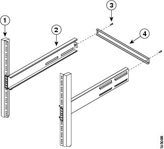
Figure 1-1 Installing the Shelf Bracket Kit into a Telco Rack
|
|
|
||
|
|
|
To install the shelf brackets in a Telco rack, follow these steps:
Step 1![]() Position a shelf bracket inside a rack-mounting rail as shown in Figure 1-1 and align the screw holes at the front of the shelf bracket with the holes in the rack-mounting rail. Then attach the shelf bracket to the rack-mounting rail using a minimum of four 12-24 or 10-24 screws.
Position a shelf bracket inside a rack-mounting rail as shown in Figure 1-1 and align the screw holes at the front of the shelf bracket with the holes in the rack-mounting rail. Then attach the shelf bracket to the rack-mounting rail using a minimum of four 12-24 or 10-24 screws.
Note![]() The bottom hole of the shelf bracket should align with the bottom hole of a rack unit on the rack-mounting rail (the hole immediately above the 1/2-in. spacing).
The bottom hole of the shelf bracket should align with the bottom hole of a rack unit on the rack-mounting rail (the hole immediately above the 1/2-in. spacing).
Step 2![]() Repeat with the other shelf bracket.
Repeat with the other shelf bracket.
Step 3![]() Verify that the shelf brackets are at the same height (using the level or tape measure as desired).
Verify that the shelf brackets are at the same height (using the level or tape measure as desired).
Step 4![]() Attach the crossbar to the rear of the shelf brackets as shown in Figure 1-1, using the 10-32 screws.
Attach the crossbar to the rear of the shelf brackets as shown in Figure 1-1, using the 10-32 screws.
Installing the Shelf Bracket Kit into a Four-Post EIA Rack
Figure 1-2 shows the installation of the shelf bracket kit into a four-post EIA rack.
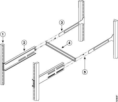
Figure 1-2 Installing the Shelf Bracket Kit into an EIA Rack
|
|
|
||
|
|
|
||
|
|
|
To install the shelf brackets in an EIA rack, follow these steps:
Step 1![]() Position a shelf bracket inside the rack-mounting rails as shown in Figure 1-2. Align the screw holes at the front of the shelf bracket with the holes in the front rack-mounting rail. Then attach the shelf bracket to the front rack-mounting rail using a minimum of four 12-24 or 10-24 screws.
Position a shelf bracket inside the rack-mounting rails as shown in Figure 1-2. Align the screw holes at the front of the shelf bracket with the holes in the front rack-mounting rail. Then attach the shelf bracket to the front rack-mounting rail using a minimum of four 12-24 or 10-24 screws.
Note![]() The bottom hole of the shelf bracket should align with the bottom hole of a rack unit on the rack-mounting rail (the hole immediately above the 1/2-in. spacing).
The bottom hole of the shelf bracket should align with the bottom hole of a rack unit on the rack-mounting rail (the hole immediately above the 1/2-in. spacing).
Step 2![]() Repeat with the other shelf bracket.
Repeat with the other shelf bracket.
Step 3![]() Verify that the shelf brackets are at the same height (using the level or tape measure as desired).
Verify that the shelf brackets are at the same height (using the level or tape measure as desired).
Step 4![]() Attach the crossbar to the shelf brackets as shown in Figure 1-2, using the 10-32 screws.
Attach the crossbar to the shelf brackets as shown in Figure 1-2, using the 10-32 screws.
Step 5![]() Insert the slider rails into the shelf brackets as shown in Figure 1-2. Then attach them to the rear rack-mounting rails using a minimum of four 12-24 or 10-24 screws.
Insert the slider rails into the shelf brackets as shown in Figure 1-2. Then attach them to the rear rack-mounting rails using a minimum of four 12-24 or 10-24 screws.
Installing the Switch on the Shelf Brackets
This section provides general instructions for installing the switch on top of the shelf brackets. For detailed installation instructions, see the “Front-Facing Installation”.

Warning![]() This unit is intended for installation in restricted access areas. A restricted access area can be accessed only through the use of a special tool, lock and key, or other means of security. Statement 1017
This unit is intended for installation in restricted access areas. A restricted access area can be accessed only through the use of a special tool, lock and key, or other means of security. Statement 1017
Warning![]() Only trained and qualified personnel should be allowed to install, replace, or service this equipment. Statement 1030
Only trained and qualified personnel should be allowed to install, replace, or service this equipment. Statement 1030
Note![]() Before you install, operate, or service the system, refer to the Regulatory Compliance and Safety Information for the Cisco MDS 9000 Family for important safety information.
Before you install, operate, or service the system, refer to the Regulatory Compliance and Safety Information for the Cisco MDS 9000 Family for important safety information.
To install the switch on top of the shelf brackets, follow these steps:
Step 1![]() Verify that the shelf brackets are level and securely attached to the rack-mounting rails, the crossbar is securely attached to the shelf brackets, and the rack is stabilized.
Verify that the shelf brackets are level and securely attached to the rack-mounting rails, the crossbar is securely attached to the shelf brackets, and the rack is stabilized.
Step 2![]() Slide the switch onto the shelf brackets, ensuring that it is squarely positioned.
Slide the switch onto the shelf brackets, ensuring that it is squarely positioned.
Step 3![]() Attach the switch to the rack-mounting rails. See the “Front-Facing Installation”.
Attach the switch to the rack-mounting rails. See the “Front-Facing Installation”.
Note![]() The grounding lug must be NRTL listed and compatible with copper conductors. Only copper conductors (wires) must be used and the copper conductor must comply with National Electrical Code (NEC) for ampacity.
The grounding lug must be NRTL listed and compatible with copper conductors. Only copper conductors (wires) must be used and the copper conductor must comply with National Electrical Code (NEC) for ampacity.
Removing the Shelf Bracket Kit (Optional)
The shelf bracket kit can be removed after the Cisco MDS 9148S switch has been installed in a four-post EIA rack, and both front rack-mount brackets and both C brackets are securely attached to the rack-mounting rails.
To remove the shelf bracket kit, follow these steps:
Step 1![]() Remove the screws fastening the slider brackets to the rear rack-mounting rails, and then slide the slider brackets out of the shelf brackets.
Remove the screws fastening the slider brackets to the rear rack-mounting rails, and then slide the slider brackets out of the shelf brackets.
Step 2![]() Remove the screws fastening the crossbar to the shelf brackets, and then remove the crossbar.
Remove the screws fastening the crossbar to the shelf brackets, and then remove the crossbar.
Step 3![]() Remove the screws fastening the shelf brackets to the front rack-mounting rails and remove the shelf brackets from the rack.
Remove the screws fastening the shelf brackets to the front rack-mounting rails and remove the shelf brackets from the rack.
 Feedback