Overview
This guide provides instructions on how to set up and configure the Cisco MDS 9100 Series Multilayer Fabric Switch in a standalone environment. This guide does not describe Host Bus Adapter (HBA) and storage array configuration. For information on how to configure HBA and storage, see the respective vendor documentation.
This section contains the following:
Prerequisites
This sections details the prerequisites that you must perform before you set up and configure the Cisco MDS 9100 Series Multilayer Fabric Switch.
The following tasks should be completed before you attempt set up the switch:
-
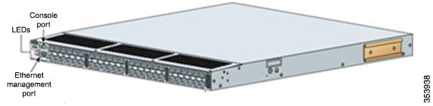
The switch is rack mounted (or installed in a cabinet), with the Small Form-factor Pluggable (SFPs) securely installed.
-
The computer is set up with the console cable and network connection.
-
The Ethernet management port is connected to the management network.
-
The cabling and connections between the switch, hosts, and storage are secured.
Besides these tasks, ensure the following:
- Access to a web browser and terminal emulator software, for example, Putty or HyperTerminal.
- Information about the Switch Name, IPv4 Address , Subnet Mask, and Default Gateway.
Setting Up Switch Management
Procedure
|
Step 1 |
Connect the serial port of the setup computer to the switch console port. |
||
|
Step 2 |
Launch the terminal emulator with the following settings: 9600 bits per second, 8 data bits, 1 stop bit, no parity, no flow control. |
||
|
Step 3 |
Power on the switch (ensure that the switch is connected to the console prior to powering on the switch so that no prompts are missed). |
||
|
Step 4 |
Enter y to abort auto provisioning and continue with normal setup. |
||
|
Step 5 |
Continue with the default options until prompted for the switch name. |
||
|
Step 6 |
Set the admin password for the switch (at least 8 characters with numbers and upper and lowercase letters). |
||
|
Step 7 |
Set the switch name. |
||
|
Step 8 |
Set the switch IPv4 address, subnet mask, and default gateway. Example:
|
||
|
Step 9 |
Continue with the default options until prompted for the default switchport port mode F. |
||
|
Step 10 |
Set default switchport port mode F to y . This setting prevents interconnect between other switches. |
Installing Device Manager
Procedure
|
Step 1 |
From your setup computer, open a web browser. |
|
Step 2 |
Access the switch using the IP address that you set in Setting Up Switch Management, Step 7. |
|
Step 3 |
Click Cisco Device Manager to download installer and click Run when prompted by Java. |
|
Step 4 |
Follow the installation wizard in Cisco Device Manager Installer to complete installation. 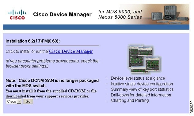 |
Confirming Port Status in Device Manager
Procedure
|
Step 1 |
Launch the Device Manager from the Java Web Start Launcher file that you downloaded. |
|
Step 2 |
Enter the username and the password. Example: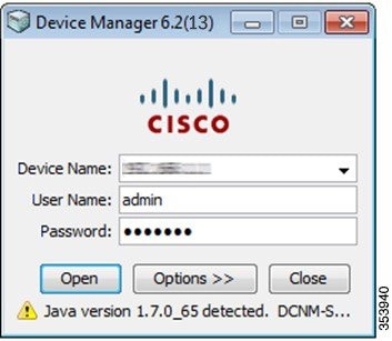 |
|
Step 3 |
After you log in, Device Manager appears. Ensure that the desired active ports show a green status. If active ports do not show green status, confirm that the SFPs and cables to hosts and storage are properly installed 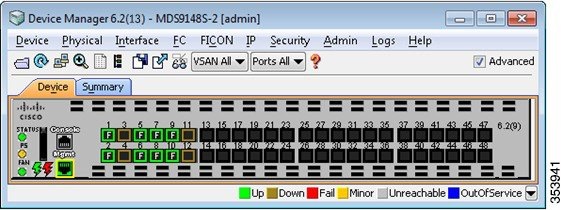 |
Running Quick Configuration for Zoning
 Note |
You need not perform the steps for Quick Configuration for Zoning, if the switch is not zoned. |
Procedure
|
Step 1 |
In the Device Manager window, click FC and select Quick Config . 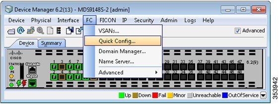 |
|
Step 2 |
In the Enable column, select all of the storage array and host ports that require configuration. All ports will be placed in VSAN 1 by default. |
|
Step 3 |
For each storage array port, select the check boxes in the Ports Zoned To column which correspond to the host ports that require a path. The corresponding check box in the row for the storage array connection is automatically selected. Both ports are now members of the same zone. 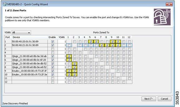 Example:Example: |
|
Step 4 |
Click Next to see a summary of the changes. |
|
Step 5 |
Review the configuration and click Finish . |
Open Zoning Configuration
If you prefer not to zone the switch, set the following parameters:
Procedure
|
Step 1 |
Set the default switchport interface state to noshut. |
|
Step 2 |
Set the default switchport trunk mode to on. |
|
Step 3 |
Set the default switchport port mode F to y. |
|
Step 4 |
Set the default zone policy to permit. |
Example
Configure default switchport interface state (shut/noshut) [shut]: noshut
Configure default switchport trunk mode (on/off/auto) [on]: on
Configure default switchport port mode F (yes/no) [n]: y
Configure default zone policy (permit/deny) [deny]: permit
Verifying Connectivity
Procedure
|
Step 1 |
From the host, verify (follow the vendor instructions) that each HBA is operational. |
|
Step 2 |
From the storage array, verify (follow the vendor instructions ) active zone and WWN assignment. |
|
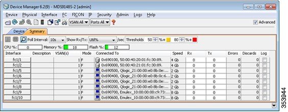
Step 3 |
From the Device Manager window, choose the Summary tab. |
|
Step 4 |
Verify that the host and storage ports are displayed. |
|
Step 5 |
Verify the zoning configuration using the show zoneset active command in the terminal emulator. |
Example
 Feedback