- Overview of Cisco CSP 2100
- Installing Cisco CSP 2100
- Maintaining Cisco CSP 2100
- Cisco CSP 2100 Specifications
- Cisco CSP 2100 Power Cord Specifications
- Overview of Cisco CSP 2100 X2
- Installing Cisco CSP 2100 X2
- Maintaining Cisco CSP 2100 X2
- Cisco CSP 2100 X2 Specifications
- Cisco CSP 2100 X2 Power Cord Specifications
Installing Cisco CSP 2100 X2
This chapter describes how to install Cisco CSP 2100 X2, and it includes the following sections:
- Unpacking and Inspecting Cisco CSP 2100 X2
- Preparing for Cisco CSP 2100 X2 Installation
- Installing Cisco CSP 2100 X2 In a Rack

Note Before you install, operate, or service Cisco CSP 2100 X2, review the Regulatory Compliance and Safety Information for Cisco Cloud Services Platform 2100 for important safety information.

Warning IMPORTANT SAFETY INSTRUCTIONS
This warning symbol means danger. You are in a situation that could cause bodily injury. Before you work on any equipment, be aware of the hazards involved with electrical circuitry and be familiar with standard practices for preventing accidents. Use the statement number provided at the end of each warning to locate its translation in the translated safety warnings that accompanied this device.
Statement 1071
Unpacking and Inspecting Cisco CSP 2100 X2

Caution When handling internal Cisco CSP 2100 X2 components, wear an ESD strap and handle modules by the carrier edges only.

Tip Keep the shipping container in case Cisco CSP 2100 X2 requires shipping in the future.
Note The chassis is thoroughly inspected before shipment. If any damage occurred during transportation or any items are missing, contact your customer service representative immediately.
Step 1 Remove Cisco CSP 2100 X2 from its cardboard container and save all packaging material.
Step 2 Compare the shipment to the equipment list provided by your customer service representative. Verify that you have all items.
Step 3 Check for damage and report any discrepancies or damage to your customer service representative. Have the following information ready:
- Invoice number of shipper (see the packing slip)
- Model and serial number of the damaged unit
- Description of damage
- Effect of damage on the installation
Preparing for Cisco CSP 2100 X2 Installation
This section provides information about preparing for Cisco CSP 2100 X2 installation, and it includes the following topics:
- Installation Guidelines
- Rack Requirements
- Equipment Requirements
- Slide Rail Adjustment Range and Cable Management Arm Dimensions
Installation Guidelines
Warning To prevent the system from overheating, do not operate it in an area that exceeds the maximum recommended ambient temperature of: 35° C (95° F).
Statement 1047
Warning The plug-socket combination must be accessible at all times, because it serves as the main disconnecting device.
Statement 1019
Warning This product relies on the building’s installation for short-circuit (overcurrent) protection. Ensure that the protective device is rated not greater than: 250 V, 15 A.
Statement 1005
Warning Installation of the equipment must comply with local and national electrical codes.
Statement 1074
Caution To ensure proper airflow it is necessary to rack Cisco CSP 2100 X2s using rail kits. Physically placing the units on top of one another or “stacking” without the use of the rail kits blocks the air vents on top of Cisco CSP 2100 X2, which could result in overheating, higher fan speeds, and higher power consumption. We recommend that you mount your Cisco CSP 2100 X2s on rail kits when you are installing them into the rack because these rails provide the minimal spacing required between Cisco CSP 2100 X2s. No additional spacing between Cisco CSP 2100 X2s is required when you mount the units using rail kits.
Caution Avoid UPS types that use ferroresonant technology. These UPS types can become unstable with systems such as Cisco CSP 2100, which can have substantial current draw fluctuations from fluctuating data traffic patterns.
When you are installing a Cisco CSP 2100 X2, use the following guidelines:
- Plan your site configuration and prepare the site before installing Cisco CSP 2100 X2. The site planning for Cisco CSP 2100 is similar to that for Cisco UCS server. See the Cisco UCS Site Preparation Guide for the recommended site planning tasks.
- Ensure that there is adequate space around Cisco CSP 2100 X2 to allow for servicing Cisco CSP 2100 X2 and for adequate airflow. The airflow in Cisco CSP 2100 X2 is from front to back.
- Ensure that the air-conditioning meets the thermal requirements listed in the Cisco CSP 2100 X2 Specifications.
- Ensure that the cabinet or rack meets the requirements listed in the “Rack Requirements” section.
- Ensure that the site power meets the power requirements listed in the Cisco CSP 2100 X2 Specifications. If available, you can use an uninterruptible power supply (UPS) to protect against power failures.
Rack Requirements
This section provides the requirements for the standard open racks.
The rack must be of the following type:
- A standard 19-in. (48.3-cm) wide, four-post EIA rack, with mounting posts that conform to English universal hole spacing, per section 1 of ANSI/EIA-310-D-1992.
- The rack post holes can be square 0.38-inch (9.6 mm), round 0.28-inch (7.1 mm), #12-24 UNC, or #10-32 UNC when you use the supplied slide rails.
- The minimum vertical rack space per Cisco CSP 2100 X2 must be two RUs, equal to 3.5 in. (88.9 mm).
Equipment Requirements
The slide rails supplied by Cisco Systems for Cisco CSP 2100 X2 do not require tools for installation if you install them in a rack that has square 0.38-inch (9.6 mm), round 0.28-inch (7.1 mm), or #12-24 UNC threaded holes.
Installing Cisco CSP 2100 X2 In a Rack
Installing the Slide Rails
This section describes how to install Cisco CSP 2100 X2 in a rack using the rack kits that are sold by Cisco.
Warning To prevent bodily injury when mounting or servicing this unit in a rack, you must take special precautions to ensure that the system remains stable. The following guidelines are provided to ensure your safety:
This unit should be mounted at the bottom of the rack if it is the only unit in the rack.
When mounting this unit in a partially filled rack, load the rack from the bottom to the top with the heaviest component at the bottom of the rack.
If the rack is provided with stabilizing devices, install the stabilizers before mounting or servicing the unit in the rack. Statement 1006
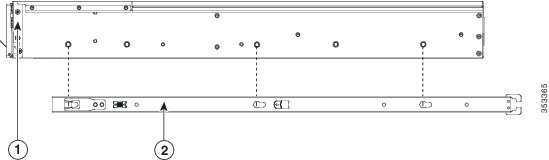
Step 1 Attach the inner rails to the sides of Cisco CSP 2100 X2:
a. Align an inner rail with one side of Cisco CSP 2100 X2 so that the three keyed slots in the rail align with the three pegs on the side of Cisco CSP 2100 X2 (see Figure 7-1).
b. Set the keyed slots over the pegs, and then slide the rail toward the front to lock it in place on the pegs. The front slot has a metal clip that locks over the front peg.
c. Install the second inner rail to the opposite side of Cisco CSP 2100 X2.
Figure 7-1 Attaching Inner Rail to Side of Cisco CSP 2100 X2
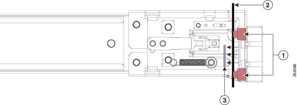
Step 2 Open the front securing plate on both slide-rail assemblies. The front end of the slide-rail assembly has a spring-loaded securing plate that must be open before you can insert the mounting pegs into the rack-post holes (see Figure 7-2).
On the outside of the assembly, push the green arrow button toward the rear to open the securing plate.
Figure 7-2 Front Securing Mechanism, Inside of Front End
Step 3 Install the slide rails into the rack:
a. Align one slide-rail assembly front end with the front rack-post holes that you want to use.
The slide rail front-end wraps around the outside of the rack post and the mounting pegs enter the rack-post holes from the outside-front (see Figure 7-2).
Note The rack post must be between the mounting pegs and the open securing plate.
b. Push the mounting pegs into the rack-post holes from the outside-front.
c. Press the securing plate release button, marked “PUSH.” The spring-loaded securing plate closes to lock the pegs in place.
d. Adjust the slide-rail length, and then push the rear mounting pegs into the corresponding rear rack-post holes. The slide rail must be level front-to-rear.
The rear mounting pegs enter the rear rack-post holes from the inside of the rack post.
e. Attach the second slide-rail assembly to the opposite side of the rack. Ensure that the two slide-rail assemblies are at the same height with each other and are level front-to-back.
f. Pull the inner slide rails on each assembly out toward the rack front until they hit the internal stops and lock in place.
Step 4 Insert Cisco CSP 2100 X2 into the slide rails:
Caution Cisco CSP 2100 X2 can weigh up to 67 pounds (30 kilograms) when fully loaded with components. We recommend that you use a minimum of two people or a mechanical lift when lifting Cisco CSP 2100 X2. Attempting this procedure alone could result in personal injury or equipment damage.
a. Align the rear of the inner rails that are attached to Cisco CSP 2100 X2 sides with the front ends of the empty slide rails on the rack.
b. Push the inner rails into the slide rails on the rack until they stop at the internal stops.
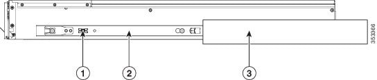
c. Slide the release clip toward the rear on both inner rails (Figure 7-3), and then continue pushing Cisco CSP 2100 X2 into the rack until its front slam latches engage with the rack posts.
Figure 7-3 Inner Rail Release Clip
Step 5 (Optional) Secure Cisco CSP 2100 X2 in the rack more permanently by using the two screws that are provided with the slide rails. Perform this step if you plan to move the rack with Cisco CSP 2100 X2 installed.
With Cisco CSP 2100 X2 fully pushed into the slide rails, open a hinged slam latch lever on the front of Cisco CSP 2100 X2 and insert the screw through the hole that is under the lever. The screw threads into the static part of the rail on the rack post and prevents Cisco CSP 2100 X2 from being pulled out. Repeat for the opposite slam latch.
 Feedback