Provisioning Layer 3 Outside Connections

Layer 3 Outside Connections

Configuring a Tenant Layer 3 Outside Network Connection Overview

This topic provides a typical example of how to configure a Layer 3 Outside for tenant networks when using Cisco APIC.


Note


Cisco ACI does not support IP fragmentation. Therefore, when you configure Layer 3 Outside (L3Out) connections to external routers, or Multi-Pod connections through an Inter-Pod Network (IPN), it is recommended that the interface MTU is set appropriately on both ends of a link. On some platforms, such as Cisco ACI, Cisco NX-OS, and Cisco IOS, the configurable MTU value does not take into account the Ethernet headers (matching IP MTU, and excluding the 14-18 Ethernet header size), while other platforms, such as IOS-XR, include the Ethernet header in the configured MTU value. A configured value of 9000 results in a max IP packet size of 9000 bytes in Cisco ACI, Cisco NX-OS, and Cisco IOS, but results in a max IP packet size of 8986 bytes for an IOS-XR untagged interface.

For the appropriate MTU values for each platform, see the relevant configuration guides.

We highly recommend that you test the MTU using CLI-based commands. For example, on the Cisco NX-OS CLI, use a command such as ping 1.1.1.1 df-bit packet-size 9000 source-interface ethernet 1/1.


Configuring Layer 3 Outside for Tenant Networks Using the REST API

The external routed network that is configured in the example can also be extended to support both IPv4 and IPv6. Both IPv4 and IPv6 routes can be advertised to and learned from the external routed network. To configure an L3Out for a tenant network, send a post with XML such as the example.

This example is broken into steps for clarity. For a merged example, see REST API Example: L3Out.

Before you begin

  • Configure the node, port, functional profile, AEP, and Layer 3 domain.

  • Create the external routed domain and associate it to the interface for the L3Out.

  • Configure a BGP route reflector policy to propagate the routes within the fabric.

For an XML example of these prerequisites, see REST API Example: L3Out Prerequisites.

Procedure


Step 1

Configure the tenant, VRF, and bridge domain.

This example configures tenant t1 with VRF v1 and bridge domain bd1. The tenant, VRF, and BD are not yet deployed.

Example:

<fvTenant  name="t1">
    <fvCtx name="v1"/>
    <fvBD name="bd1">
        <fvRsCtx tnFvCtxName="v1"/>
        <fvSubnet ip="44.44.44.1/24" scope="public"/>
        <fvRsBDToOut tnL3extOutName="l3out1"/>
    </fvBD>/>
</fvTenant>

Step 2

Configure an application profile and application EPG.

This example configures application profile app1 (on node 101), EPG epg1, and associates the EPG with bd1 and the contract httpCtrct, as the consumer.

Example:

<fvAp name="app1">
    <fvAEPg name="epg1">
        <fvRsDomAtt instrImedcy="immediate" tDn="uni/phys-dom1"/>
        <fvRsBd tnFvBDName="bd1" />
        <fvRsPathAtt encap="vlan-2011" instrImedcy="immediate" mode="regular" tDn="topology/pod-1/paths-101/pathep-[eth1/3]"/>
        <fvRsCons tnVzBrCPName="httpCtrct"/>
    </fvAEPg>
</fvAp>

Step 3

Configure the node and interface.

This example configures VRF v1 on node 103 (the border leaf switch), with the node profile, nodep1, and router ID 11.11.11.103. It also configures interface eth1/3 as a routed interface (Layer 3 port), with IP address 12.12.12.1/24 and Layer 3 domain dom1.

Example:

<l3extOut name="l3out1">
    <l3extRsEctx tnFvCtxName="v1"/>
    <l3extLNodeP name="nodep1">
        <l3extRsNodeL3OutAtt rtrId="11.11.11.103" tDn="topology/pod-1/node-103"/>
        <l3extLIfP name="ifp1"/>
         <l3extRsPathL3OutAtt addr="12.12.12.3/24" ifInstT="l3-port" tDn="topology/pod-1/paths-103/pathep-[eth1/3]"/>
        </l3extLIfP>
    </l3extLNodeP>
    <l3extRsL3DomAtt tDn="uni/l3dom-dom1"/>
</l3extOut>

Step 4

Configure the routing protocol.

This example configures BGP as the primary routing protocol, with a BGP peer with the IP address, 15.15.15.2 and ASN 100.

Example:

<l3extOut name="l3out1">
    <l3extLNodeP name="nodep1">
        <bgpPeerP addr="15.15.15.2">
            <bgpAsP asn="100"/>
        </bgpPeerP>
    </l3extLNodeP>
    <bgpExtP/>
</l3extOut>

Step 5

Configure the connectivity routing protocol.

This example configures OSPF as the communication protocol, with regular area ID 0.0.0.0.

Example:

<l3extOut name="l3out1">
    <ospfExtP areaId="0.0.0.0" areaType="regular"/>
    <l3extLNodeP name="nodep1">
        <l3extLIfP name="ifp1">
            <ospfIfP/>
        <l3extIfP>
    <l3extLNodeP>
</l3extOut>

Step 6

Configure the external EPG.

This example configures the network 20.20.20.0/24 as external network extnw1. It also associates extnw1 with the route control profile rp1 and the contract httpCtrct, as the provider.

Example:

<l3extOut name="l3out1">
    <l3extInstP name="extnw1">
        <l3extSubnet ip="20.20.20.0/24" scope="import-security"/>
        <fvRsProv tnVzBrCPName="httpCtrct"/>
    </l3extInstP> 
</l3extOut>

Step 7

Optional. Configure a route map.

This example configures a route map for the BGP peer in the outbound direction. The route map is applied for routes that match a destination of 200.3.2.0/24. Also, on a successful match (if the route matches this range) the route AS PATH attribute is updated to 200 and 100.

Example:

<fvTenant name="t1">
    <rtctrlSubjP name="match-rule1">
         <rtctrlMatchRtDest ip="200.3.2.0/24"/>
    </rtctrlSubjP>
    <l3extOut name="l3out1">
        <rtctrlProfile name="rp1">
            <rtctrlCtxP name="ctxp1" action="permit" order="0">
                <rtctrlScope>
                    <rtctrlRsScopeToAttrP tnRtctrlAttrPName="attrp1"/>
                </rtctrlScope>
                <rtctrlRsCtxPToSubjP tnRtctrlSubjPName="match-rule1"/>
            </rtctrlCtxP>
        </rtctrlProfile>
        <l3extInstP name="extnw1">
            <l3extSubnet ip="20.20.20.0/24" scope="import-security"/>
            <l3extRsInstPToProfile direction='export' tnRtctrlProfileName="rp1"/>
            <fvRsProv tnVzBrCPName="httpCtrct"/>
        </l3extInstP>
    </l3extOut>
</fvTenant>

Step 8

This example creates filters and contracts to enable the EPGs to communicate. The external EPG and the application EPG are already associated with the contract httpCtrct as provider and consumer respectively. The scope of the contract (where it is applied) can be within the application profile, the tenant, the VRF, or it can be used globally (throughout the fabric). In this example, the scope is the VRF (context).

Example:

<vzFilter name="http-filter">
    <vzEntry  name="http-e" etherT="ip" prot="tcp"/>
</vzFilter>
<vzBrCP name="httpCtrct" scope="context">
    <vzSubj name="subj1">
        <vzRsSubjFiltAtt tnVzFilterName="http-filter"/>
    </vzSubj>
</vzBrCP>

REST API Example: L3Out Prerequisites

This example configures the node, port, functional profile, AEP, and Layer 3 domain:

<?xml version="1.0" encoding="UTF-8"?>
<!-- api/policymgr/mo/.xml -->
<polUni>
    <infraInfra>
        <!-- Node profile -->
        <infraNodeP name="nodeP1">
            <infraLeafS name="leafS1" type="range">
                <infraNodeBlk name="NodeBlk1" from_="101" to_="103" />
            </infraLeafS>
            <infraRsAccPortP tDn="uni/infra/accportprof-PortP1" />
        </infraNodeP>
        <!-- Port profile -->
        <infraAccPortP name="PortP1">
            <!-- 12 regular ports -->
            <infraHPortS name="PortS1" type="range">
                <infraPortBlk name="portBlk1" fromCard="1" toCard="1" fromPort="3" toPort="32"/>
                <infraRsAccBaseGrp tDn="uni/infra/funcprof/accportgrp-default" />
            </infraHPortS>
        </infraAccPortP>
        <!-- Functional profile -->
        <infraFuncP>
            <!-- Regular port group -->
            <infraAccPortGrp name="default">
                <infraRsAttEntP tDn="uni/infra/attentp-aeP1" />
            </infraAccPortGrp>
        </infraFuncP>
        <infraAttEntityP name="aeP1">
            <infraRsDomP tDn="uni/phys-dom1"/>
            <infraRsDomP tDn="uni/l3dom-dom1/>
        </infraAttEntityP>
        <fvnsVlanInstP name="vlan-1024-2048" allocMode="static">
             <fvnsEncapBlk name="encap" from="vlan-1024" to="vlan-2048" status="created"/>
        </fvnsVlanInstP>
    </infraInfra>
    <physDomP dn="uni/phys-dom1" name="dom1">
         <infraRsVlanNs tDn="uni/infra/vlanns-[vlan-1024-2048]-static"/>
    </physDomP>
    <l3extDomP name="dom1">
        <infraRsVlanNs tDn="uni/infra/vlanns-[vlan-1024-2048]-static" />
    </l3extDomP>
</polUni>

The following example configures the required BGP route reflectors:

 <!-- Spine switches 104 and 105 are configured as route reflectors -->
<?xml version="1.0" encoding="UTF8"?>
<!-- api/policymgr/mo/.xml -->
<polUni>
    <bgpInstPol name="default">
        <bgpAsP asn="100"/>
        <bgpRRP>
            <bgpRRNodePEp id="104"/>
            <bgpRRNodePEp id="105"/>
        </bgpRRP>  
    </bgpInstPol>
    <fabricFuncP>
        <fabricPodPGrp name="bgpRRPodGrp1">
            <fabricRsPodPGrpBGPRRP tnBgpInstPolName="default"/>
        </fabricPodPGrp>
    </fabricFuncP> 
    <fabricPodP name="default">
        <fabricPodS name="default" type="ALL">
            <fabricRsPodPGrp tDn="uni/fabric/funcprof/podpgrp-bgpRRPodGrp1"/>
        </fabricPodS>
    </fabricPodP>
</polUni>

REST API Example: L3Out

The following example provides a merged version of the steps to configure an L3Out using the REST API.

<?xml version="1.0" encoding="UTF8"?>
<!-- api/policymgr/mo/.xml -->
<polUni>
   <fvTenant name="t1">
       <fvCtx name="v1"/>
       <fvBD name="bd1">
           <fvRsCtx tnFvCtxName="v1"/>
           <fvSubnet ip="44.44.44.1/24" scope="public"/>
           <fvRsBDToOut tnL3extOutName="l3out1"/>
       </fvBD>
       <fvAp name="app1">
           <fvAEPg name="epg1">
               <fvRsDomAtt instrImedcy="immediate" tDn="uni/phys-dom1"/>
               <fvRsBd tnFvBDName="bd1" />
               <fvRsPathAtt encap="vlan-2011" instrImedcy="immediate" mode="regular" tDn="topology/pod-1/paths-101/pathep-[eth1/3]"/>
               <fvRsCons tnVzBrCPName="httpCtrct"/>
           </fvAEPg>
       </fvAp>
       <l3extOut name="l3out1">
           <l3extRsEctx tnFvCtxName="v1"/>
           <l3extLNodeP name="nodep1">
               <l3extRsNodeL3OutAtt rtrId="11.11.11.103" tDn="topology/pod-1/node-103"/>
               <l3extLIfP name="ifp1">
                   <l3extRsPathL3OutAtt addr="12.12.12.3/24" ifInstT="l3-port" tDn="topology/pod-1/paths-103/pathep-[eth1/3]"/>
               </l3extLIfP>
               <bgpPeerP addr="15.15.15.2">
                   <bgpAsP asn="100"/>
               </bgpPeerP>
            </l3extLNodeP>
            <l3extRsL3DomAtt tDn="uni/l3dom-dom1"/>
            <bgpExtP/>
            <ospfExtP areaId="0.0.0.0" areaType="regular"/>
            <l3extInstP name="extnw1" >
                <l3extSubnet ip="20.20.20.0/24" scope="import-security"/>
                <l3extRsInstPToProfile direction="export" tnRtctrlProfileName="rp1"/>
                <fvRsProv tnVzBrCPName="httpCtrct"/>
            </l3extInstP>
            <rtctrlProfile name="rp1">
                <rtctrlCtxP name="ctxp1" action="permit" order="0">
                    <rtctrlScope>
                        <rtctrlRsScopeToAttrP tnRtctrlAttrPName="attrp1"/>
                    </rtctrlScope>
                    <rtctrlRsCtxPToSubjP tnRtctrlSubjPName="match-rule1"/>
                </rtctrlCtxP>
            </rtctrlProfile>
        </l3extOut>
        <rtctrlSubjP name="match-rule1">
            <rtctrlMatchRtDest ip="200.3.2.0/24"/>
        </rtctrlSubjP>
        <rtctrlAttrP name="attrp1">
            <rtctrlSetASPath criteria="prepend">
                <rtctrlSetASPathASN asn="100" order="2"/>
                <rtctrlSetASPathASN asn="200" order="1"/>
            </rtctrlSetASPath>
        </rtctrlAttrP>
        <vzFilter name='http-filter'>
            <vzEntry name="http-e" etherT="ip" prot="tcp"/>
        </vzFilter>
        <vzBrCP name="httpCtrct" scope="context">
            <vzSubj name="subj1">
                <vzRsSubjFiltAtt tnVzFilterName="http-filter"/>
            </vzSubj>
        </vzBrCP>
    </fvTenant>
</polUni>

REST API Example: Tenant External Network Policy

The following XML code is an example of a Tenant Layer 3 external network policy.


<polUni>

 <fvTenant name='t0'>
    <fvCtx name="o1">
        <fvRsOspfCtxPol tnOspfCtxPolName="ospfCtxPol"/>    
    </fvCtx>
    <fvCtx name="o2">
    </fvCtx>
    
    <fvBD name="bd1">
        <fvRsBDToOut tnL3extOutName='T0-o1-L3OUT-1'/>
        <fvSubnet ip='10.16.1.1/24' scope='public'/>
        <fvRsCtx tnFvCtxName="o1"/>
    </fvBD>
    
    <fvAp name="AP1">
        <fvAEPg name="bd1-epg1">
            <fvRsCons tnVzBrCPName="vzBrCP-1">
            </fvRsCons>
            <fvRsProv tnVzBrCPName="vzBrCP-1">
            </fvRsProv>
            <fvSubnet ip='10.16.2.1/24' scope='private'/>
            <fvSubnet ip='10.16.3.1/24' scope='private'/>
            <fvRsBd tnFvBDName="bd1"/>
            <fvRsDomAtt tDn="uni/phys-physDomP"/>
            <fvRsPathAtt 
                 tDn="topology/pod-1/paths-101/pathep-[eth1/40]" 
                 encap='vlan-100' 
                 mode='regular' 
                 instrImedcy='immediate' />
        </fvAEPg>
        
        <fvAEPg name="bd1-epg2">
            <fvRsCons tnVzBrCPName="vzBrCP-1">
            </fvRsCons>
            <fvRsProv tnVzBrCPName="vzBrCP-1">
            </fvRsProv>
            <fvSubnet ip='10.16.4.1/24' scope='private'/>
            <fvSubnet ip='10.16.5.1/24' scope='private'/>
            <fvRsBd tnFvBDName="bd1"/>
            <fvRsDomAtt tDn="uni/phys-physDomP"/>
            <fvRsPathAtt 
                 tDn="topology/pod-1/paths-101/pathep-[eth1/41]" 
                 encap='vlan-200' 
                 mode='regular' 
                 instrImedcy='immediate'/>
        </fvAEPg>
    </fvAp>

    <l3extOut name="T0-o1-L3OUT-1">

        <l3extRsEctx tnFvCtxName="o1"/>
        <ospfExtP areaId='60'/>
        <l3extInstP name="l3extInstP-1">
            <fvRsCons tnVzBrCPName="vzBrCP-1">
            </fvRsCons>
            <fvRsProv tnVzBrCPName="vzBrCP-1">
            </fvRsProv>
            <l3extSubnet ip="192.5.1.0/24" />
            <l3extSubnet ip="192.5.2.0/24" />
            <l3extSubnet ip="192.6.0.0/16" />
            <l3extSubnet ip="199.0.0.0/8" />
        </l3extInstP>

        <l3extLNodeP name="l3extLNodeP-1">
            <l3extRsNodeL3OutAtt 
                 tDn=“topology/pod-1/node-101" rtrId="10.17.1.1">
                 <ipRouteP ip="10.16.101.1/32">
                      <ipNexthopP nhAddr="10.17.1.99"/>
                 </ipRouteP>
                 <ipRouteP ip="10.16.102.1/32">
                      <ipNexthopP nhAddr="10.17.1.99"/>
                 </ipRouteP>        
		               <ipRouteP ip="10.17.1.3/32">
            		        <ipNexthopP nhAddr="10.11.2.2"/>
        		       </ipRouteP> 
            </l3extRsNodeL3OutAtt > 
 
            <l3extLIfP name='l3extLIfP-1'>
                <l3extRsPathL3OutAtt 
                     tDn=“topology/pod-1/paths-101/pathep-[eth1/25]" 
                     encap='vlan-1001' 
                     ifInstT='sub-interface' 
                     addr="10.11.2.1/24" 
                     mtu="1500"/>
                <ospfIfP>
                    <ospfRsIfPol tnOspfIfPolName='ospfIfPol'/>
                </ospfIfP>
            </l3extLIfP>
        </l3extLNodeP>
    </l3extOut>

    <ospfIfPol name="ospfIfPol" />
    <ospfCtxPol name="ospfCtxPol" />

    <vzFilter name="vzFilter-in-1">
         <vzEntry name="vzEntry-in-1"/>
    </vzFilter>
    <vzFilter name="vzFilter-out-1">
         <vzEntry name="vzEntry-out-1"/>
    </vzFilter>

    <vzBrCP name="vzBrCP-1">
       <vzSubj name="vzSubj-1">
           <vzInTerm>
               <vzRsFiltAtt tnVzFilterName="vzFilter-in-1"/>
           </vzInTerm>
           <vzOutTerm>
               <vzRsFiltAtt tnVzFilterName="vzFilter-out-1"/>
           </vzOutTerm>
       </vzSubj>
   </vzBrCP>    
 </fvTenant> 
</polUni>

Cisco ACI GOLF

Cisco ACI GOLF

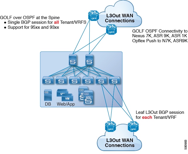
The Cisco ACI GOLF feature (also known as Layer 3 EVPN Services for Fabric WAN) enables much more efficient and scalable ACI fabric WAN connectivity. It uses the BGP EVPN protocol over OSPF for WAN routers that are connected to spine switches.

Figure 1. Cisco ACI GOLF Topology


All tenant WAN connections use a single session on the spine switches where the WAN routers are connected. This aggregation of tenant BGP sessions towards the Data Center Interconnect Gateway (DCIG) improves control plane scale by reducing the number of tenant BGP sessions and the amount of configuration required for all of them. The network is extended out using Layer 3 subinterfaces configured on spine fabric ports. Transit routing with shared services using GOLF is not supported.

A Layer 3 external outside network (L3extOut) for GOLF physical connectivity for a spine switch is specified under the infra tenant, and includes the following:

  • LNodeP (l3extInstP is not required within the L3Out in the infra tenant. )

  • A provider label for the L3extOut for GOLF in the infra tenant.

  • OSPF protocol policies

  • BGP protocol policies

All regular tenants use the above-defined physical connectivity. The L3extOut defined in regular tenants requires the following:

  • An l3extInstP (EPG) with subnets and contracts. The scope of the subnet is used to control import/export route control and security policies. The bridge domain subnet must be set to advertise externally and it must be in the same VRF as the application EPG and the GOLF L3Out EPG.

  • Communication between the application EPG and the GOLF L3Out EPG is governed by explicit contracts (not Contract Preferred Groups).

  • An l3extConsLbl consumer label that must be matched with the same provider label of an L3Out for GOLF in the infra tenant. Label matching enables application EPGs in other tenants to consume the LNodeP external L3Out EPG.

  • The BGP EVPN session in the matching provider L3extOut in the infra tenant advertises the tenant routes defined in this L3Out.

Configuring GOLF Using the REST API

Procedure


Step 1

The following example shows how to deploy nodes and spine switch interfaces for GOLF, using the REST API:

Example:

POST 
https://192.0.20.123/api/mo/uni/golf.xml

Step 2

The XML below configures the spine switch interfaces and infra tenant provider of the GOLF service. Include this XML structure in the body of the POST message.

Example:

<l3extOut descr="" dn="uni/tn-infra/out-golf" enforceRtctrl="export,import" 
    name="golf" 
    ownerKey="" ownerTag="" targetDscp="unspecified">
    <l3extRsEctx tnFvCtxName="overlay-1"/>
    <l3extProvLbl descr="" name="golf" 
         ownerKey="" ownerTag="" tag="yellow-green"/>
    <l3extLNodeP configIssues="" descr="" 
         name="bLeaf" ownerKey="" ownerTag="" 
         tag="yellow-green" targetDscp="unspecified">
         <l3extRsNodeL3OutAtt rtrId="10.10.3.3" rtrIdLoopBack="no" 
             tDn="topology/pod-1/node-111">
             <l3extInfraNodeP descr="" fabricExtCtrlPeering="yes" name=""/>
             <l3extLoopBackIfP addr="10.10.3.3" descr="" name=""/>
         </l3extRsNodeL3OutAtt>
         <l3extRsNodeL3OutAtt rtrId="10.10.3.4" rtrIdLoopBack="no" 
             tDn="topology/pod-1/node-112">
         <l3extInfraNodeP descr="" fabricExtCtrlPeering="yes" name=""/>
         <l3extLoopBackIfP addr="10.10.3.4" descr="" name=""/>
         </l3extRsNodeL3OutAtt>
         <l3extLIfP descr="" name="portIf-spine1-3" 
             ownerKey="" ownerTag="" tag="yellow-green">
             <ospfIfP authKeyId="1" authType="none" descr="" name="">
               <ospfRsIfPol tnOspfIfPolName="ospfIfPol"/>
             </ospfIfP>
             <l3extRsNdIfPol tnNdIfPolName=""/>
             <l3extRsIngressQosDppPol tnQosDppPolName=""/>
             <l3extRsEgressQosDppPol tnQosDppPolName=""/>
             <l3extRsPathL3OutAtt addr="7.2.1.1/24" descr="" 
                encap="vlan-4" 
                encapScope="local" 
                ifInstT="sub-interface" 
                llAddr="::" mac="00:22:BD:F8:19:FF" 
                mode="regular" 
                mtu="1500" 
                tDn="topology/pod-1/paths-111/pathep-[eth1/12]" 
                targetDscp="unspecified"/>
          </l3extLIfP>
          <l3extLIfP descr="" name="portIf-spine2-1" 
              ownerKey="" 
              ownerTag="" 
              tag="yellow-green">
              <ospfIfP authKeyId="1" 
                   authType="none" 
                   descr="" 
                   name="">
                   <ospfRsIfPol tnOspfIfPolName="ospfIfPol"/>
              </ospfIfP>
              <l3extRsNdIfPol tnNdIfPolName=""/>
              <l3extRsIngressQosDppPol tnQosDppPolName=""/>
              <l3extRsEgressQosDppPol tnQosDppPolName=""/>
              <l3extRsPathL3OutAtt addr="7.1.0.1/24" descr="" 
                   encap="vlan-4" 
                   encapScope="local" 
                   ifInstT="sub-interface" 
                   llAddr="::" mac="00:22:BD:F8:19:FF" 
                   mode="regular" 
                   mtu="9000" 
                   tDn="topology/pod-1/paths-112/pathep-[eth1/11]" 
                   targetDscp="unspecified"/>
           </l3extLIfP>
           <l3extLIfP descr="" name="portif-spine2-2" 
              ownerKey="" 
              ownerTag="" 
              tag="yellow-green">
              <ospfIfP authKeyId="1" 
                   authType="none" descr="" 
                   name="">
                   <ospfRsIfPol tnOspfIfPolName="ospfIfPol"/>
             </ospfIfP>
             <l3extRsNdIfPol tnNdIfPolName=""/>
             <l3extRsIngressQosDppPol tnQosDppPolName=""/>
             <l3extRsEgressQosDppPol tnQosDppPolName=""/>
             <l3extRsPathL3OutAtt addr="7.2.2.1/24" descr="" 
                   encap="vlan-4" 
                   encapScope="local" 
                   ifInstT="sub-interface" 
                          llAddr="::" mac="00:22:BD:F8:19:FF" 
                          mode="regular" 
                          mtu="1500" 
                          tDn="topology/pod-1/paths-112/pathep-[eth1/12]" 
                          targetDscp="unspecified"/>
             </l3extLIfP>
             <l3extLIfP descr="" name="portIf-spine1-2" 
                  ownerKey="" ownerTag="" tag="yellow-green">
                  <ospfIfP authKeyId="1" authType="none" descr="" name="">
                       <ospfRsIfPol tnOspfIfPolName="ospfIfPol"/>
                  </ospfIfP>
                  <l3extRsNdIfPol tnNdIfPolName=""/>
                  <l3extRsIngressQosDppPol tnQosDppPolName=""/>
                  <l3extRsEgressQosDppPol tnQosDppPolName=""/>
                  <l3extRsPathL3OutAtt addr="9.0.0.1/24" descr="" 
                   encap="vlan-4" 
                   encapScope="local" 
                   ifInstT="sub-interface" 
                        llAddr="::" mac="00:22:BD:F8:19:FF" 
                        mode="regular" 
                        mtu="9000" 
                        tDn="topology/pod-1/paths-111/pathep-[eth1/11]" 
                        targetDscp="unspecified"/>
             </l3extLIfP>
             <l3extLIfP descr="" name="portIf-spine1-1" 
                   ownerKey="" ownerTag="" tag="yellow-green">
                   <ospfIfP authKeyId="1" authType="none" descr="" name="">
                        <ospfRsIfPol tnOspfIfPolName="ospfIfPol"/>
                   </ospfIfP>
                   <l3extRsNdIfPol tnNdIfPolName=""/>
                   <l3extRsIngressQosDppPol tnQosDppPolName=""/>
                   <l3extRsEgressQosDppPol tnQosDppPolName=""/>
                   <l3extRsPathL3OutAtt addr="7.0.0.1/24" descr="" 
                     encap="vlan-4" 
                     encapScope="local" 
                     ifInstT="sub-interface" 
                     llAddr="::" mac="00:22:BD:F8:19:FF" 
                     mode="regular" 
                     mtu="1500" 
                     tDn="topology/pod-1/paths-111/pathep-[eth1/10]" 
                          targetDscp="unspecified"/>
             </l3extLIfP>
             <bgpInfraPeerP addr="10.10.3.2" 
                allowedSelfAsCnt="3" 
                ctrl="send-com,send-ext-com" 
                descr="" name="" peerCtrl="" 
                peerT="wan" 
                privateASctrl="" ttl="2" weight="0">
                <bgpRsPeerPfxPol tnBgpPeerPfxPolName=""/>
                <bgpAsP asn="150" descr="" name="aspn"/>
             </bgpInfraPeerP>
             <bgpInfraPeerP addr="10.10.4.1" 
                allowedSelfAsCnt="3" 
                ctrl="send-com,send-ext-com" descr="" name="" peerCtrl="" 
                peerT="wan" 
                privateASctrl="" ttl="1" weight="0">
                <bgpRsPeerPfxPol tnBgpPeerPfxPolName=""/>
                <bgpAsP asn="100" descr="" name=""/>
              </bgpInfraPeerP>
              <bgpInfraPeerP addr="10.10.3.1" 
                allowedSelfAsCnt="3" 
                ctrl="send-com,send-ext-com" descr="" name="" peerCtrl="" 
                peerT="wan" 
                privateASctrl="" ttl="1" weight="0">
                <bgpRsPeerPfxPol tnBgpPeerPfxPolName=""/>
                <bgpAsP asn="100" descr="" name=""/>
             </bgpInfraPeerP>
       </l3extLNodeP>
       <bgpRtTargetInstrP descr="" name="" ownerKey="" ownerTag="" rtTargetT="explicit"/>
       <l3extRsL3DomAtt tDn="uni/l3dom-l3dom"/>
       <l3extInstP descr="" matchT="AtleastOne" name="golfInstP" 
                 prio="unspecified" 
                 targetDscp="unspecified">
                 <fvRsCustQosPol tnQosCustomPolName=""/>
        </l3extInstP>
        <bgpExtP descr=""/>
        <ospfExtP areaCost="1" 
               areaCtrl="redistribute,summary" 
               areaId="0.0.0.1" 
               areaType="regular" descr=""/>
</l3extOut>
 

Step 3

The XML below configures the tenant consumer of the infra part of the GOLF service. Include this XML structure in the body of the POST message.

Example:

<fvTenant descr="" dn="uni/tn-pep6" name="pep6" ownerKey="" ownerTag="">
     <vzBrCP descr="" name="webCtrct" 
          ownerKey="" ownerTag="" prio="unspecified" 
          scope="global" targetDscp="unspecified">
          <vzSubj consMatchT="AtleastOne" descr="" 
               name="http" prio="unspecified" provMatchT="AtleastOne" 
               revFltPorts="yes" targetDscp="unspecified">
               <vzRsSubjFiltAtt directives="" tnVzFilterName="default"/>
          </vzSubj>
      </vzBrCP>
      <vzBrCP descr="" name="webCtrct-pod2" 
           ownerKey="" ownerTag="" prio="unspecified" 
           scope="global" targetDscp="unspecified">
           <vzSubj consMatchT="AtleastOne" descr="" 
                name="http" prio="unspecified" 
                provMatchT="AtleastOne" revFltPorts="yes" 
                targetDscp="unspecified">
                <vzRsSubjFiltAtt directives="" 
                      tnVzFilterName="default"/>
           </vzSubj>
       </vzBrCP>
       <fvCtx descr="" knwMcastAct="permit" 
            name="ctx6" ownerKey="" ownerTag="" 
            pcEnfDir="ingress" pcEnfPref="enforced">
            <bgpRtTargetP af="ipv6-ucast" 
                 descr="" name="" ownerKey="" ownerTag="">
                 <bgpRtTarget descr="" name="" ownerKey="" ownerTag="" 
                 rt="route-target:as4-nn2:100:1256" 
                 type="export"/>
                 <bgpRtTarget descr="" name="" ownerKey="" ownerTag="" 
                      rt="route-target:as4-nn2:100:1256" 
                      type="import"/>
            </bgpRtTargetP>
            <bgpRtTargetP af="ipv4-ucast" 
                 descr="" name="" ownerKey="" ownerTag="">
                 <bgpRtTarget descr="" name="" ownerKey="" ownerTag="" 
                      rt="route-target:as4-nn2:100:1256" 
                      type="export"/>
                 <bgpRtTarget descr="" name="" ownerKey="" ownerTag="" 
                      rt="route-target:as4-nn2:100:1256" 
                      type="import"/>
            </bgpRtTargetP>
            <fvRsCtxToExtRouteTagPol tnL3extRouteTagPolName=""/>
            <fvRsBgpCtxPol tnBgpCtxPolName=""/>
            <vzAny descr="" matchT="AtleastOne" name=""/>
            <fvRsOspfCtxPol tnOspfCtxPolName=""/>
            <fvRsCtxToEpRet tnFvEpRetPolName=""/>
            <l3extGlobalCtxName descr="" name="dci-pep6"/>
       </fvCtx>
       <fvBD arpFlood="no" descr="" epMoveDetectMode="" 
            ipLearning="yes" 
            limitIpLearnToSubnets="no" 
            llAddr="::" mac="00:22:BD:F8:19:FF" 
            mcastAllow="no" 
            multiDstPktAct="bd-flood" 
            name="bd107" ownerKey="" ownerTag="" type="regular" 
            unicastRoute="yes" 
            unkMacUcastAct="proxy" 
            unkMcastAct="flood" 
            vmac="not-applicable">
            <fvRsBDToNdP tnNdIfPolName=""/>
            <fvRsBDToOut tnL3extOutName="routAccounting-pod2"/>
            <fvRsCtx tnFvCtxName="ctx6"/>
            <fvRsIgmpsn tnIgmpSnoopPolName=""/>
            <fvSubnet ctrl="" descr="" ip="27.6.1.1/24" 
                 name="" preferred="no" 
                 scope="public" 
                 virtual="no"/>
                 <fvSubnet ctrl="nd" descr="" ip="2001:27:6:1::1/64" 
                      name="" preferred="no" 
                      scope="public" 
                      virtual="no">
                      <fvRsNdPfxPol tnNdPfxPolName=""/>
                 </fvSubnet>
                 <fvRsBdToEpRet resolveAct="resolve" tnFvEpRetPolName=""/>
       </fvBD>
       <fvBD arpFlood="no" descr="" epMoveDetectMode="" 
            ipLearning="yes" 
            limitIpLearnToSubnets="no" 
            llAddr="::" mac="00:22:BD:F8:19:FF" 
            mcastAllow="no" 
            multiDstPktAct="bd-flood" 
            name="bd103" ownerKey="" ownerTag="" type="regular" 
            unicastRoute="yes" 
            unkMacUcastAct="proxy" 
            unkMcastAct="flood" 
            vmac="not-applicable">
            <fvRsBDToNdP tnNdIfPolName=""/>
            <fvRsBDToOut tnL3extOutName="routAccounting"/>
            <fvRsCtx tnFvCtxName="ctx6"/>
            <fvRsIgmpsn tnIgmpSnoopPolName=""/>
            <fvSubnet ctrl="" descr="" ip="23.6.1.1/24" 
                 name="" preferred="no" 
                 scope="public" 
                 virtual="no"/>
            <fvSubnet ctrl="nd" descr="" ip="2001:23:6:1::1/64" 
                 name="" preferred="no" 
                 scope="public" virtual="no">
                 <fvRsNdPfxPol tnNdPfxPolName=""/>
            </fvSubnet>
            <fvRsBdToEpRet resolveAct="resolve" tnFvEpRetPolName=""/>
       </fvBD>
       <vnsSvcCont/>
       <fvRsTenantMonPol tnMonEPGPolName=""/>
       <fvAp descr="" name="AP1" 
            ownerKey="" ownerTag="" prio="unspecified">
            <fvAEPg descr="" 
                 isAttrBasedEPg="no" 
                 matchT="AtleastOne" 
                 name="epg107" 
                 pcEnfPref="unenforced" prio="unspecified">
                 <fvRsCons prio="unspecified" 
                      tnVzBrCPName="webCtrct-pod2"/>
                 <fvRsPathAtt descr="" 
                      encap="vlan-1256" 
                      instrImedcy="immediate" 
                      mode="regular" primaryEncap="unknown" 
                      tDn="topology/pod-2/paths-107/pathep-[eth1/48]"/>
                 <fvRsDomAtt classPref="encap" delimiter="" 
                      encap="unknown" 
                      instrImedcy="immediate" 
                      primaryEncap="unknown" 
                      resImedcy="lazy" tDn="uni/phys-phys"/>
                 <fvRsCustQosPol tnQosCustomPolName=""/>
                 <fvRsBd tnFvBDName="bd107"/>
                 <fvRsProv matchT="AtleastOne" 
                      prio="unspecified" 
                      tnVzBrCPName="default"/>
            </fvAEPg>
            <fvAEPg descr="" 
                 isAttrBasedEPg="no" 
                 matchT="AtleastOne" 
                 name="epg103" 
                 pcEnfPref="unenforced" prio="unspecified">
                 <fvRsCons prio="unspecified" tnVzBrCPName="default"/>
                 <fvRsCons prio="unspecified" tnVzBrCPName="webCtrct"/>
                 <fvRsPathAtt descr="" encap="vlan-1256" 
                      instrImedcy="immediate" 
                      mode="regular" primaryEncap="unknown" 
                      tDn="topology/pod-1/paths-103/pathep-[eth1/48]"/>
                      <fvRsDomAtt classPref="encap" delimiter="" 
                           encap="unknown" 
                           instrImedcy="immediate" 
                           primaryEncap="unknown" 
                           resImedcy="lazy" tDn="uni/phys-phys"/>
                      <fvRsCustQosPol tnQosCustomPolName=""/>
                      <fvRsBd tnFvBDName="bd103"/>
            </fvAEPg>
       </fvAp>
       <l3extOut descr="" 
            enforceRtctrl="export" 
            name="routAccounting-pod2" 
            ownerKey="" ownerTag="" targetDscp="unspecified">
            <l3extRsEctx tnFvCtxName="ctx6"/>
            <l3extInstP descr="" 
                 matchT="AtleastOne" 
                 name="accountingInst-pod2" 
                 prio="unspecified" targetDscp="unspecified">
            <l3extSubnet aggregate="export-rtctrl,import-rtctrl" 
                 descr="" ip="::/0" name="" 
                 scope="export-rtctrl,import-rtctrl,import-security"/>
            <l3extSubnet aggregate="export-rtctrl,import-rtctrl" 
                 descr="" 
                 ip="0.0.0.0/0" name="" 
                 scope="export-rtctrl,import-rtctrl,import-security"/>
            <fvRsCustQosPol tnQosCustomPolName=""/>
            <fvRsProv matchT="AtleastOne" 
                 prio="unspecified" tnVzBrCPName="webCtrct-pod2"/>
            </l3extInstP>
            <l3extConsLbl descr="" 
                 name="golf2" 
                 owner="infra" 
                 ownerKey="" ownerTag="" tag="yellow-green"/>
       </l3extOut>
       <l3extOut descr="" 
            enforceRtctrl="export" 
            name="routAccounting" 
            ownerKey="" ownerTag="" targetDscp="unspecified">
            <l3extRsEctx tnFvCtxName="ctx6"/>
            <l3extInstP descr="" 
                 matchT="AtleastOne" 
                 name="accountingInst" 
                 prio="unspecified" targetDscp="unspecified">
            <l3extSubnet aggregate="export-rtctrl,import-rtctrl" descr="" 
                 ip="0.0.0.0/0" name="" 
                 scope="export-rtctrl,import-rtctrl,import-security"/>
            <fvRsCustQosPol tnQosCustomPolName=""/>
            <fvRsProv matchT="AtleastOne" prio="unspecified" tnVzBrCPName="webCtrct"/>
            </l3extInstP>
            <l3extConsLbl descr="" 
                 name="golf" 
                 owner="infra" 
                 ownerKey="" ownerTag="" tag="yellow-green"/>
       </l3extOut>
</fvTenant>
 

Distributing BGP EVPN Type-2 Host Routes to a DCIG

In APIC up to release 2.0(1f), the fabric control plane did not send EVPN host routes directly, but advertised public bridge domain (BD) subnets in the form of BGP EVPN type-5 (IP Prefix) routes to a Data Center Interconnect Gateway (DCIG). This could result in suboptimal traffic forwarding. To improve forwarding, in APIC release 2.1x, you can enable fabric spines to also advertise host routes using EVPN type-2 (MAC-IP) host routes to the DCIG along with the public BD subnets.

To do so, you must perform the following steps:

  1. When you configure the BGP Address Family Context Policy, enable Host Route Leak.

  2. When you leak the host route to BGP EVPN in a GOLF setup:

    1. To enable host routes when GOLF is enabled, the BGP Address Family Context Policy must be configured under the application tenant (the application tenant is the consumer tenant that leaks the endpoint to BGP EVPN) rather than under the infrastructure tenant.

    2. For a single-pod fabric, the host route feature is not required. The host route feature is required to avoid sub-optimal forwarding in a multi-pod fabric setup. However, if a single-pod fabric is setup, then in order to leak the endpoint to BGP EVPN, a Fabric External Connection Policy must be configured to provide the ETEP IP address. Otherwise, the host route will not leak to BGP EVPN.

  3. When you configure VRF properties:

    1. Add the BGP Address Family Context Policy to the BGP Context Per Address Families for IPv4 and IPv6.

    2. Configure BGP Route Target Profiles that identify routes that can be imported or exported from the VRF.

Enabling Distributing BGP EVPN Type-2 Host Routes to a DCIG Using the REST API

Enable distributing BGP EVPN type-2 host routes using the REST API, as follows:

Before you begin

EVPN services must be configured.

Procedure


Step 1

Configure the Host Route Leak policy, with a POST containing XML such as in the following example:

Example:

<bgpCtxAfPol descr="" ctrl="host-rt-leak" name="bgpCtxPol_0 status=""/>

Step 2

Apply the policy to the VRF BGP Address Family Context Policy for one or both of the address families using a POST containing XML such as in the following example:

Example:

<fvCtx name="vni-10001">
<fvRsCtxToBgpCtxAfPol af="ipv4-ucast" tnBgpCtxAfPolName="bgpCtxPol_0"/>
<fvRsCtxToBgpCtxAfPol af="ipv6-ucast" tnBgpCtxAfPolName="bgpCtxPol_0"/>
</fvCtx>
   

Multipod

Multipod

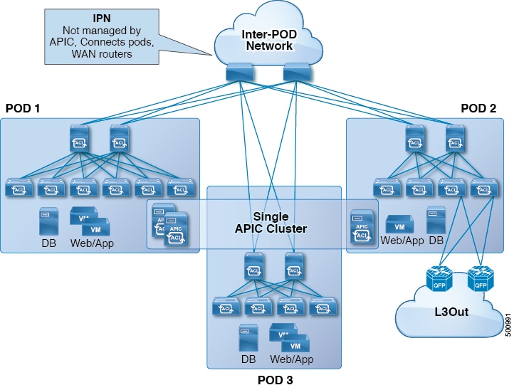
Multipod enables provisioning a more fault tolerant fabric comprised of multiple pods with isolated control plane protocols. Also, multipod provides more flexibility with regard to the full mesh cabling between leaf and spine switches. For example, if leaf switches are spread across different floors or different buildings, multipod enables provisioning multiple pods per floor or building and providing connectivity between pods through spine switches.

Multipod uses MP-BGP EVPN as the control-plane communication protocol between the ACI spines in different Pods. WAN routers can be provisioned in the IPN, directly connected to spine switches, or connected to border leaf switches. Multipod uses a single APIC cluster for all the pods; all the pods act as a single fabric. Individual APIC controllers are placed across the pods but they are all part of a single APIC cluster.

Figure 2. Multipod Overview


For control plane isolation, IS-IS and COOP are not extended across pods. Endpoints synchronize across pods using BGP EVPN over the IPN between the pods. Two spines in each pod are configured to have BGP EVPN sessions with spines of other pods. The spines connected to the IPN get the endpoints and multicast groups from COOP within a pod, but they advertise them over the IPN EVPN sessions between the pods. On the receiving side, BGP gives them back to COOP and COOP synchs them across all the spines in the pod. WAN routes are exchanged between the pods using BGP VPNv4/VPNv6 address families; they are not exchanged using the EVPN address family.

There are two modes of setting up the spine switches for communicating across pods as peers and route reflectors:

  • Automatic

    • Automatic mode is a route reflector based mode that does not support a full mesh where all spines peer with each other. The administrator must post an existing BGP route reflector policy and select IPN aware (EVPN) route reflectors. All the peer/client settings are automated by the APIC.

    • The administrator does not have an option to choose route reflectors that don’t belong to the fabric (for example, in the IPN).

  • Manual

    • The administrator has the option to configure full mesh where all spines peer with each other without route reflectors.

    • In manual mode, the administrator must post the already existing BGP peer policy.

Observe the following multipod guidelines and limitations:

  • When adding a pod to the ACI fabric, wait for the control plane to converge before adding another pod.

  • OSPF is deployed on ACI spine switches and IPN switches to provide reachability between PODs. Layer 3 subinterfaces are created on spines to connect to IPN switches. OSPF is enabled on these Layer 3 subinterfaces and per POD TEP prefixes are advertised over OSPF. There is one subinterface created on each external spine link. Provision many external links on each spine if the expectation is that the amount of east-west traffic between PODs will be large. Currently, ACI spine switches support up to 64 external links on each spine, and each subinterface can be configured for OSPF. Spine proxy TEP addresses are advertised in OSPF over all the subinterfaces leading to a maximum of 64 way ECMP on the IPN switch for proxy TEP addresses. Similarly, spines would receive proxy TEP addresses of other PODs from IPN switches over OSPF and the spine can have up to 64 way ECMP for remote pod proxy TEP addresses. In this way, traffic between PODs spread over all these external links provides the desired bandwidth.

  • When the all fabric links of a spine switch are down, OSPF advertises the TEP routes with the maximum metric. This will force the IPN switch to remove the spine switch from ECMP which will prevent the IPN from forwarding traffic to the down spine switch. Traffic is then received by other spines that have up fabric links.

  • Up to APIC release 2.0(2), multipod is not supported with GOLF. In release 2.0 (2) the two features are supported in the same fabric only over Cisco Nexus N9000K switches without “EX” on the end of the switch name; for example, N9K-9312TX. Since the 2.1(1) release, the two features can be deployed together over all the switches used in the multipod and EVPN topologies.

  • In a multipod fabric, if a spine in POD1 uses the infra tenant L3extOut-1, the TORs for the other pods ( POD2, POD3) cannot use the same infra L3extOut (L3extOut-1) for Layer 3 EVPN control plane connectivity. Each POD must use their own spine switch and infra L3extOut, because it is not supported to use a pod as a transit for WAN connectivity of other pods.

  • No filtering is done for limiting the routes exchanged across pods. All end-point and WAN routes present in each pod are exported to other pods.

  • Inband management across pods is automatically configured by a self tunnel on every spine.

  • The maximum latency supported between pods is 10 msec RTT, which roughly translates to a geographical distance of up to 500 miles.

Setting Up Multi-Pod Fabric Using the REST API

Procedure


Step 1

Login to Cisco APIC:

Example:

http://<apic-name/ip>:80/api/aaaLogin.xml

data: <aaaUser name="admin" pwd="ins3965!”/>

Step 2

Configure the TEP pool:

Example:

http://<apic-name/ip>:80/api/policymgr/mo/uni/controller.xml

<fabricSetupPol status=''>
    <fabricSetupP podId="1" tepPool="10.0.0.0/16" />
    <fabricSetupP podId="2" tepPool="10.1.0.0/16" status='' />
</fabricSetupPol>

Step 3

Configure the node ID policy:

Example:

http://<apic-name/ip>:80/api/node/mo/uni/controller.xml

<fabricNodeIdentPol>
<fabricNodeIdentP serial="SAL1819RXP4" name="ifav4-leaf1" nodeId="101" podId="1"/>
<fabricNodeIdentP serial="SAL1803L25H" name="ifav4-leaf2" nodeId="102" podId="1"/>
<fabricNodeIdentP serial="SAL1934MNY0" name="ifav4-leaf3" nodeId="103" podId="1"/>
<fabricNodeIdentP serial="SAL1934MNY3" name="ifav4-leaf4" nodeId="104" podId="1"/>
<fabricNodeIdentP serial="SAL1748H56D" name="ifav4-spine1" nodeId="201" podId="1"/>
<fabricNodeIdentP serial="SAL1938P7A6" name="ifav4-spine3" nodeId="202" podId="1"/>
<fabricNodeIdentP serial="SAL1938PHBB" name="ifav4-leaf5" nodeId="105" podId="2"/>
<fabricNodeIdentP serial="SAL1942R857" name="ifav4-leaf6" nodeId="106" podId="2"/>
<fabricNodeIdentP serial="SAL1931LA3B" name="ifav4-spine2" nodeId="203" podId="2"/>
<fabricNodeIdentP serial="FGE173400A9" name="ifav4-spine4" nodeId="204" podId="2"/>
</fabricNodeIdentPol>

Step 4

Configure infra L3Out and external connectivity profile:

Example:

http://<apic-name/ip>:80/api/node/mo/uni.xml

<polUni>

<fvTenant descr="" dn="uni/tn-infra" name="infra" ownerKey="" ownerTag="">

   <l3extOut descr="" enforceRtctrl="export" name="multipod" ownerKey="" ownerTag="" targetDscp="unspecified" status=''>
      <ospfExtP areaId='0' areaType='regular' status=''/>
      <l3extRsEctx tnFvCtxName="overlay-1"/>
      <l3extProvLbl descr="" name="prov_mp1" ownerKey="" ownerTag="" tag="yellow-green"/>

      <l3extLNodeP name="bSpine">
         <l3extRsNodeL3OutAtt rtrId="201.201.201.201" rtrIdLoopBack="no" tDn="topology/pod-1/node-201">
            <l3extInfraNodeP descr="" fabricExtCtrlPeering="yes" name=""/>
            <l3extLoopBackIfP addr="201::201/128" descr="" name=""/>
            <l3extLoopBackIfP addr="201.201.201.201/32" descr="" name=""/>
         </l3extRsNodeL3OutAtt>

         <l3extRsNodeL3OutAtt rtrId="202.202.202.202" rtrIdLoopBack="no" tDn="topology/pod-1/node-202">
            <l3extInfraNodeP descr="" fabricExtCtrlPeering="yes" name=""/>
            <l3extLoopBackIfP addr="202::202/128" descr="" name=""/>
            <l3extLoopBackIfP addr="202.202.202.202/32" descr="" name=""/>
         </l3extRsNodeL3OutAtt>
         
         <l3extRsNodeL3OutAtt rtrId="203.203.203.203" rtrIdLoopBack="no" tDn="topology/pod-2/node-203">
            <l3extInfraNodeP descr="" fabricExtCtrlPeering="yes" name=""/>
            <l3extLoopBackIfP addr="203::203/128" descr="" name=""/>
            <l3extLoopBackIfP addr="203.203.203.203/32" descr="" name=""/>
         </l3extRsNodeL3OutAtt>

         <l3extRsNodeL3OutAtt rtrId="204.204.204.204" rtrIdLoopBack="no" tDn="topology/pod-2/node-204">
            <l3extInfraNodeP descr="" fabricExtCtrlPeering="yes" name=""/>
            <l3extLoopBackIfP addr="204::204/128" descr="" name=""/>
            <l3extLoopBackIfP addr="204.204.204.204/32" descr="" name=""/>
         </l3extRsNodeL3OutAtt>         

         <l3extLIfP name='portIf'>
            <l3extRsPathL3OutAtt descr='asr' tDn="topology/pod-1/paths-201/pathep-[eth1/1]" encap='vlan-4'  ifInstT='sub-interface' addr="201.1.1.1/30" />
            <l3extRsPathL3OutAtt descr='asr' tDn="topology/pod-1/paths-201/pathep-[eth1/2]" encap='vlan-4'  ifInstT='sub-interface' addr="201.2.1.1/30" />
            <l3extRsPathL3OutAtt descr='asr' tDn="topology/pod-1/paths-202/pathep-[eth1/2]" encap='vlan-4'  ifInstT='sub-interface' addr="202.1.1.1/30" />
            <l3extRsPathL3OutAtt descr='asr' tDn="topology/pod-2/paths-203/pathep-[eth1/1]" encap='vlan-4'  ifInstT='sub-interface' addr="203.1.1.1/30" />
            <l3extRsPathL3OutAtt descr='asr' tDn="topology/pod-2/paths-203/pathep-[eth1/2]" encap='vlan-4'  ifInstT='sub-interface' addr="203.2.1.1/30" />
            <l3extRsPathL3OutAtt descr='asr' tDn="topology/pod-2/paths-204/pathep-[eth4/31]" encap='vlan-4'  ifInstT='sub-interface' addr="204.1.1.1/30" />          

           <ospfIfP>
               <ospfRsIfPol tnOspfIfPolName='ospfIfPol'/>
           </ospfIfP>

         </l3extLIfP>
      </l3extLNodeP>

      <l3extInstP descr="" matchT="AtleastOne" name="instp1" prio="unspecified" targetDscp="unspecified">
          <fvRsCustQosPol tnQosCustomPolName=""/>
      </l3extInstP>
   </l3extOut>

   <fvFabricExtConnP descr="" id="1" name="Fabric_Ext_Conn_Pol1" rt="extended:as2-nn4:5:16" status=''>
      <fvPodConnP descr="" id="1" name="">
         <fvIp addr="100.11.1.1/32"/>
      </fvPodConnP>
      <fvPodConnP descr="" id="2" name="">
         <fvIp addr="200.11.1.1/32"/>
      </fvPodConnP>
      <fvPeeringP descr="" name="" ownerKey="" ownerTag="" type="automatic_with_full_mesh"/>
      <l3extFabricExtRoutingP descr="" name="ext_routing_prof_1" ownerKey="" ownerTag="">
         <l3extSubnet aggregate="" descr="" ip="100.0.0.0/8" name="" scope="import-security"/>
         <l3extSubnet aggregate="" descr="" ip="200.0.0.0/8" name="" scope="import-security"/>
         <l3extSubnet aggregate="" descr="" ip="201.1.0.0/16" name="" scope="import-security"/>
         <l3extSubnet aggregate="" descr="" ip="201.2.0.0/16" name="" scope="import-security"/>
         <l3extSubnet aggregate="" descr="" ip="202.1.0.0/16" name="" scope="import-security"/>
         <l3extSubnet aggregate="" descr="" ip="203.1.0.0/16" name="" scope="import-security"/>
         <l3extSubnet aggregate="" descr="" ip="203.2.0.0/16" name="" scope="import-security"/>
         <l3extSubnet aggregate="" descr="" ip="204.1.0.0/16" name="" scope="import-security"/>
      </l3extFabricExtRoutingP>
   </fvFabricExtConnP>
</fvTenant>
</polUni>

Remote Leaf Switches

About Remote Leaf Switches in the ACI Fabric

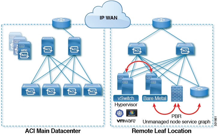
With an ACI fabric deployed, you can extend ACI services and APIC management to remote datacenters with Cisco ACI leaf switches that have no local spine switch or APIC attached.

Figure 3. Remote Leaf Topology

The remote leaf switches are added to an existing pod in the fabric. All policies deployed in the main datacenter are deployed in the remote switches, which behave like local leaf switches belonging to the pod. In this topology, all unicast traffic is through VXLAN over Layer 3. Layer 2 Broadcast, Unknown Unicast, and Multicast (BUM) messages are sent using Head End Replication (HER) tunnels without the use of Multicast. All local traffic on the remote site is switched directly between endpoints, whether physical or virtual. Any traffic that requires use of the spine switch proxy is forwarded to the main datacenter.

The APIC system discovers the remote leaf switches when they come up. From that time, they can be managed through APIC, as part of the fabric.


Note


  • All inter-VRF traffic goes to the spine switch before being forwarded.

  • Before decommissioning a remote leaf, you must first delete the vPC.


You can configure Remote Leaf in the APIC GUI, either with and without a wizard, or use the REST API or the NX-OS style CLI.

Remote Leaf Switch Hardware Requirements

The following switches are supported for the Remote Leaf Switch feature.

Fabric Spine Switches

For the spine switch at the ACI Main Datacenter that is connected to the WAN router, the following spine switches are supported:

  • Fixed spine switches Cisco Nexus 9000 series:

    • N9K-C9316D-GX

    • N9K-C9332C

    • N9K-C9364C

    • N9K-C9364C-GX

  • For modular spine switches, only Cisco Nexus 9000 series switches with names that end in EX, and later (for example, N9K-X9732C- EX ) are supported.

  • Older generation spine switches, such as the fixed spine switch N9K-C9336PQ or modular spine switches with the N9K-X9736PQ linecard are supported in the Main Datacenter, but only next generation spine switches are supported to connect to the WAN.

Remote Leaf Switches

  • For the remote leaf switches, only Cisco Nexus 9000 series switches with names that end in EX, and later (for example, N9K-C93180LC-EX) are supported.

  • The remote leaf switches must be running a switch image of 13.1.x or later (aci-n9000-dk9.13.1.x.x.bin) before they can be discovered. This may require manual upgrades on the leaf switches.

Remote Leaf Switch Restrictions and Limitations

The following guidelines and restrictions apply to remote leaf switches:

  • A remote leaf vPC pair has a split brain condition when the DP-TEP address of one of the switches is not reachable from the peer. In this case, both remote leaf switches are up and active in the fabric and the COOP session is also up on both of the peers. One of the remote leaf switches does not have a route to the DP-TEP address of its peer, and due to this, the vPC has a split brain condition. Both of the node roles is changed to "primary" and all the front panel links are up in both of the peers while the zero message queue (ZMQ) session is down.

  • The remote leaf solution requires the /32 tunnel end point (TEP) IP addresses of the remote leaf switches and main data center leaf/spine switches to be advertised across the main data center and remote leaf switches without summarization.

  • If you move a remote leaf switch to a different site within the same pod and the new site has the same node ID as the original site, you must delete and recreate the virtual port channel (vPC).

  • With the Cisco N9K-C9348GC-FXP switch, you can perform the initial remote leaf switch discovery only on ports 1/53 or 1/54. Afterward, you can use the other ports for fabric uplinks to the ISN/IPN for the remote leaf switch.

The following sections provide information on what is supported and not supported with remote leaf switches:

Supported Features

Beginning with Cisco APIC release 3.2(x), the following features are supported:

  • FEX devices connected to remote leaf switches

  • Cisco AVS with VLAN and Cisco AVS with VXLAN

  • Cisco ACI Virtual Edge with VLAN and ACI Virtual Edge with VXLAN

  • The Cisco Nexus 9336C-FX2 switch is now supported for remote leaf switches

Unsupported Features

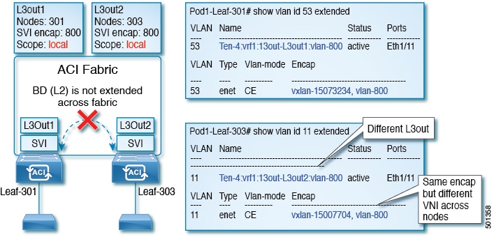
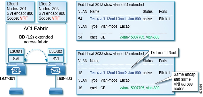
Stretching of an L3Out SVI between local leaf switches (ACI main data center switches) and remote leaf switches is not supported.

The following deployments and configurations are not supported with the remote leaf switch feature:

  • APIC controllers directly connected to remote leaf switches

  • Orphan port-channel or physical ports on remote leaf switches, with a vPC domain (this restriction applies for releases 3.1 and earlier)

  • With and without service node integration, local traffic forwarding within a remote location is only supported if the consumer, provider, and services nodes are all connected to Remote Leaf switches are in vPC mode

Full fabric and tenant policies are supported on remote leaf switches in this release with the exception of the following features, which are unsupported:

  • GOLF

  • vPod

  • Floating L3Out

  • Fast-convergence mode

  • Stretching of L3Out SVI between local leaf switches (ACI main data center switches) and remote leaf switches or stretching across two different vPC pairs of remote leaf switches

  • Copy service is not supported when deployed on local leaf switches and when the source or destination is on the remote leaf switch. In this situation, the routable TEP IP address is not allocated for the local leaf switch. For more information, see the section "Copy Services Limitations" in the "Configuring Copy Services" chapter in the Cisco APIC Layer 4 to Layer 7 Services Deployment Guide, available in the APIC documentation page.

  • ACI Multi-Site

  • Layer 2 Outside Connections (except Static EPGs)

  • 802.1Q Tunnels

  • Copy services with vzAny contract

  • FCoE connections on remote leaf switches

  • Flood in encapsulation for bridge domains or EPGs

  • Fast Link Failover policies

  • Managed Service Graph-attached devices at remote locations

  • Netflow

  • PBR Tracking on remote leaf switches (with system-level global GIPo enabled)

  • Q-in-Q Encapsulation Mapping for EPGs

  • Traffic Storm Control

  • Cloud Sec and MacSec Encryption

  • First Hop Security

  • Layer 3 Multicast routing on remote leaf switches

  • Openstack and Kubernetes VMM domains

  • Maintenance mode

  • Troubleshooting wizard

  • Transit L3Out across remote locations, which is when the main Cisco ACI data center pod is a transit between two remote locations (the L3Out in RL location-1 and L3Out in RL location-2 are advertising prefixes for each other)

  • Traffic forwarding directly across two remote leaf vPC pairs in the same remote data center or across data centers, when those remote leaf pairs are associated to the same pod or to pods that are part of the same multipod fabric

The following scenarios are not supported when integrating remote leaf switches in a Multi-Site architecture in conjunction with the intersite L3Out functionality:

  • Transit routing between L3Outs deployed on remote leaf switch pairs associated to separate sites

  • Endpoints connected to a remote leaf switch pair associated to a site communicating with the L3Out deployed on the remote leaf switch pair associated to a remote site

  • Endpoints connected to the local site communicating with the L3Out deployed on the remote leaf switch pair associated to a remote site

  • Endpoints connected to a remote leaf switch pair associated to a site communicating with the L3Out deployed on a remote site


Note


The limitations above do not apply if the different data center sites are deployed as pods as part of the same Multi-Pod fabric.


WAN Router and Remote Leaf Switch Configuration Guidelines

Before a remote leaf is discovered and incorporated in APIC management, you must configure the WAN router and the remote leaf switches.

Configure the WAN routers that connect to the fabric spine switch external interfaces and the remote leaf switch ports, with the following requirements:

WAN Routers

  • Enable OSPF on the interfaces, with the same details, such as area ID, type, and cost.

  • Configure DHCP Relay on the interface leading to each APIC's IP address in the main fabric.

  • The interfaces on the WAN routers which connect to the VLAN-5 interfaces on the spine switches must be on different VRFs than the interfaces connecting to a regular multipod network.

Remote Leaf Switches

  • Connect the remote leaf switches to an upstream router by a direct connection from one of the fabric ports. The following connections to the upstream router are supported:

    • 40 Gbps & higher connections

    • With a QSFP-to-SFP Adapter, supported 1G/10G SFPs

    Bandwidth in the WAN must be a minimum of 100 Mbps and maximum supported latency is 300 msecs.

  • It is recommended, but not required to connect the pair of remote leaf switches with a vPC. The switches on both ends of the vPC must be remote leaf switches at the same remote datacenter.

  • Configure the northbound interfaces as Layer 3 sub-interfaces on VLAN-4, with unique IP addresses.

    If you connect more than one interface from the remote leaf switch to the router, configure each interface with a unique IP address.

  • Enable OSPF on the interfaces, but do not set the OSPF area type as stub area.

  • The IP addresses in the remote leaf switch TEP Pool subnet must not overlap with the pod TEP subnet pool. The subnet used must be /24 or lower.

  • Multipod is supported, but not required, with the Remote Leaf feature.

  • When connecting a pod in a single-pod fabric with remote leaf switches, configure an L3Out from a spine switch to the WAN router and an L3Out from a remote leaf switch to the WAN router, both using VLAN-4 on the switch interfaces.

  • When connecting a pod in a multipod fabric with remote leaf switches, configure an L3Out from a spine switch to the WAN router and an L3Out from a remote leaf switch to the WAN router, both using VLAN-4 on the switch interfaces. Also configure a multipod-internal L3Out using VLAN-5 to support traffic that crosses pods destined to a remote leaf switch. The regular multipod and multipod-internal connections can be configured on the same physical interfaces, as long as they use VLAN-4 and VLAN-5.

  • When configuring the Multipod-internal L3Out, use the same router ID as for the regular multipod L3Out, but deselect the Use Router ID as Loopback Address option for the router-id and configure a different loopback IP address. This enables ECMP to function.

Configure Remote Leaf Switches Using the REST API

To enable Cisco APIC to discover and connect the IPN router and remote leaf switches, perform the steps in this topic.

This example assumes that the remote leaf switches are connected to a pod in a multipod topology. It includes two L3Outs configured in the infra tenant, with VRF overlay-1:

  • One is configured on VLAN-4, that is required for both the remote leaf switches and the spine switch connected to the WAN router.

  • One is the multipod-internal L3Out configured on VLAN-5, that is required for the multipod and Remote Leaf features, when they are deployed together.

Procedure


Step 1

To define the TEP pool for two remote leaf switches to be connected to a pod, send a post with XML such as the following example:

Example:

<fabricSetupPol>
      <fabricSetupP tepPool="10.0.0.0/16" podId="1" >
           <fabricExtSetupP tepPool="30.0.128.0/20" extPoolId="1"/>
     </fabricSetupP>
     <fabricSetupP tepPool="10.1.0.0/16" podId="2" >
          <fabricExtSetupP tepPool="30.1.128.0/20" extPoolId="1"/>
     </fabricSetupP>
</fabricSetupPol>

Step 2

To define the node identity policy, send a post with XML, such as the following example:

Example:

<fabricNodeIdentPol>
     <fabricNodeIdentP serial="SAL17267Z7W" name="leaf1" nodeId="101" podId="1" 
extPoolId="1" nodeType="remote-leaf-wan"/>
     <fabricNodeIdentP serial="SAL17267Z7X" name="leaf2" nodeId="102" podId="1" 
extPoolId="1" nodeType="remote-leaf-wan"/>
     <fabricNodeIdentP serial="SAL17267Z7Y" name="leaf3" nodeId="201" podId="1" 
extPoolId="1" nodeType="remote-leaf-wan"/>
     <fabricNodeIdentP serial="SAL17267Z7Z" name="leaf4" nodeId="201" podId="1" 
extPoolId="1" nodeType="remote-leaf-wan"/>
</fabricNodeIdentPol>

Step 3

To configure the Fabric External Connection Profile, send a post with XML such as the following example:

Example:

<?xml version="1.0" encoding="UTF-8"?>
<imdata totalCount="1">
     <fvFabricExtConnP dn="uni/tn-infra/fabricExtConnP-1" id="1" name="Fabric_Ext_Conn_Pol1" rt="extended:as2-nn4:5:16" siteId="0">
           <l3extFabricExtRoutingP name="test">
                <l3extSubnet ip="150.1.0.0/16" scope="import-security"/>
           </l3extFabricExtRoutingP>
          <l3extFabricExtRoutingP name="ext_routing_prof_1">
               <l3extSubnet ip="204.1.0.0/16" scope="import-security"/>
               <l3extSubnet ip="209.2.0.0/16" scope="import-security"/>
               <l3extSubnet ip="202.1.0.0/16" scope="import-security"/>
               <l3extSubnet ip="207.1.0.0/16" scope="import-security"/>
               <l3extSubnet ip="200.0.0.0/8" scope="import-security"/>
               <l3extSubnet ip="201.2.0.0/16" scope="import-security"/>
               <l3extSubnet ip="210.2.0.0/16" scope="import-security"/>
               <l3extSubnet ip="209.1.0.0/16" scope="import-security"/>
               <l3extSubnet ip="203.2.0.0/16" scope="import-security"/>
               <l3extSubnet ip="208.1.0.0/16" scope="import-security"/>
               <l3extSubnet ip="207.2.0.0/16" scope="import-security"/>
               <l3extSubnet ip="100.0.0.0/8" scope="import-security"/>
               <l3extSubnet ip="201.1.0.0/16" scope="import-security"/>
               <l3extSubnet ip="210.1.0.0/16" scope="import-security"/>
               <l3extSubnet ip="203.1.0.0/16" scope="import-security"/>
               <l3extSubnet ip="208.2.0.0/16" scope="import-security"/>
          </l3extFabricExtRoutingP>
          <fvPodConnP id="1">
                <fvIp addr="100.11.1.1/32"/>
         </fvPodConnP>
         <fvPodConnP id="2">
               <fvIp addr="200.11.1.1/32"/>
         </fvPodConnP>
         <fvPeeringP type="automatic_with_full_mesh"/>
     </fvFabricExtConnP>
</imdata>

Step 4

To configure an L3Out on VLAN-4, that is required for both the remote leaf switches and the spine switch connected to the WAN router, enter XML such as the following example:

Example:

<?xml version="1.0" encoding="UTF-8"?>
<polUni>
<fvTenant name="infra">
  <l3extOut name="rleaf-wan-test">
    <ospfExtP areaId="0.0.0.5"/>
    <bgpExtP/>
    <l3extRsEctx tnFvCtxName="overlay-1"/>
    <l3extRsL3DomAtt tDn="uni/l3dom-l3extDom1"/>
    <l3extProvLbl descr="" name="prov_mp1" ownerKey="" ownerTag="" tag="yellow-green"/>
    <l3extLNodeP name="rleaf-101">
      <l3extRsNodeL3OutAtt rtrId="202.202.202.202" tDn="topology/pod-1/node-101">
      </l3extRsNodeL3OutAtt>
      <l3extLIfP name="portIf">
        <l3extRsPathL3OutAtt ifInstT="sub-interface" tDn="topology/pod-1/paths-101/pathep-[eth1/49]" addr="202.1.1.2/30" mac="AA:11:22:33:44:66" encap='vlan-4'/>
        <ospfIfP>
          <ospfRsIfPol tnOspfIfPolName='ospfIfPol'/>
        </ospfIfP>
      </l3extLIfP>
    </l3extLNodeP>
    <l3extLNodeP name="rlSpine-201">
      <l3extRsNodeL3OutAtt rtrId="201.201.201.201" rtrIdLoopBack="no" tDn="topology/pod-1/node-201">
        <!--
        <l3extLoopBackIfP addr="201::201/128" descr="" name=""/>
        <l3extLoopBackIfP addr="201.201.201.201/32" descr="" name=""/>
        -->
        <l3extLoopBackIfP addr="::" />
      </l3extRsNodeL3OutAtt>
      <l3extLIfP name="portIf">
        <l3extRsPathL3OutAtt ifInstT="sub-interface" tDn="topology/pod-1/paths-201/pathep-[eth8/36]" addr="201.1.1.1/30" mac="00:11:22:33:77:55" encap='vlan-4'/>
        <ospfIfP>
          <ospfRsIfPol tnOspfIfPolName='ospfIfPol'/>
        </ospfIfP>
      </l3extLIfP>
    </l3extLNodeP>
    <l3extInstP descr="" matchT="AtleastOne" name="instp1" prio="unspecified" targetDscp="unspecified">
      <fvRsCustQosPol tnQosCustomPolName=""/>
    </l3extInstP>
  </l3extOut>
  <ospfIfPol name="ospfIfPol" nwT="bcast"/>
</fvTenant>
</polUni>

Step 5

To configure the multipod L3Out on VLAN-5, that is required for both multipod and the remote leaf topology, send a post such as the following example:

Example:

<?xml version="1.0" encoding="UTF-8"?>                    
<polUni>                                                                                               
  <fvTenant  name="infra" >
    <l3extOut name="ipn-multipodInternal">
      <ospfExtP areaCtrl="inherit-ipsec,redistribute,summary" areaId="0.0.0.5" multipodInternal="yes" />
      <l3extRsEctx tnFvCtxName="overlay-1" />
      <l3extLNodeP name="bLeaf">
        <l3extRsNodeL3OutAtt rtrId="202.202.202.202" rtrIdLoopBack="no" tDn="topology/pod-2/node-202">
            <l3extLoopBackIfP addr="202.202.202.212"/>
       </l3extRsNodeL3OutAtt>
        <l3extRsNodeL3OutAtt rtrId="102.102.102.102" rtrIdLoopBack="no" tDn="topology/pod-1/node-102">
            <l3extLoopBackIfP addr="102.102.102.112"/>
       </l3extRsNodeL3OutAtt>
        <l3extLIfP name="portIf">
          <ospfIfP authKeyId="1" authType="none">
            <ospfRsIfPol tnOspfIfPolName="ospfIfPol" />
          </ospfIfP>
          <l3extRsPathL3OutAtt addr="10.0.254.233/30" encap="vlan-5" ifInstT="sub-interface" tDn="topology/pod-2/paths-202/pathep-[eth5/2]"/>
          <l3extRsPathL3OutAtt addr="10.0.255.229/30" encap="vlan-5" ifInstT="sub-interface" tDn="topology/pod-1/paths-102/pathep-[eth5/2]"/>
        </l3extLIfP>
      </l3extLNodeP>
      <l3extInstP matchT="AtleastOne" name="ipnInstP" />
    </l3extOut>
  </fvTenant>
</polUni>

Prerequisites Required Prior to Downgrading Remote Leaf Switches


Note


If you have remote leaf switches deployed, if you downgrade the APIC software from Release 3.1(1) or later, to an earlier release that does not support the Remote Leaf feature, you must decommission the remote nodes and remove the remote leaf-related policies (including the TEP Pool), before downgrading. For more information on decommissioning switches, see Decommissioning and Recommissioning Switches in the Cisco APIC Troubleshooting Guide.


Before you downgrade remote leaf switches, verify that the followings tasks are complete:

  • Delete the vPC domain.

  • Delete the vTEP - Virtual Network Adapter if using SCVMM.

  • Decommission the remote leaf nodes, and wait 10 -15 minutes after the decommission for the task to complete.

  • Delete the remote leaf to WAN L3out in the infra tenant.

  • Delete the infra-l3out with VLAN 5 if using Multipod.

  • Delete the remote TEP pools.

HSRP

About HSRP

HSRP is a first-hop redundancy protocol (FHRP) that allows a transparent failover of the first-hop IP router. HSRP provides first-hop routing redundancy for IP hosts on Ethernet networks configured with a default router IP address. You use HSRP in a group of routers for selecting an active router and a standby router. In a group of routers, the active router is the router that routes packets, and the standby router is the router that takes over when the active router fails or when preset conditions are met.

Many host implementations do not support any dynamic router discovery mechanisms but can be configured with a default router. Running a dynamic router discovery mechanism on every host is not practical for many reasons, including administrative overhead, processing overhead, and security issues. HSRP provides failover services to such hosts.

When you use HSRP, you configure the HSRP virtual IP address as the default router of the host (instead of the IP address of the actual router). The virtual IP address is an IPv4 or IPv6 address that is shared among a group of routers that run HSRP.

When you configure HSRP on a network segment, you provide a virtual MAC address and a virtual IP address for the HSRP group. You configure the same virtual address on each HSRP-enabled interface in the group. You also configure a unique IP address and MAC address on each interface that acts as the real address. HSRP selects one of these interfaces to be the active router. The active router receives and routes packets destined for the virtual MAC address of the group.

HSRP detects when the designated active router fails. At that point, a selected standby router assumes control of the virtual MAC and IP addresses of the HSRP group. HSRP also selects a new standby router at that time.

HSRP uses a priority designator to determine which HSRP-configured interface becomes the default active router. To configure an interface as the active router, you assign it with a priority that is higher than the priority of all the other HSRP-configured interfaces in the group. The default priority is 100, so if you configure just one interface with a higher priority, that interface becomes the default active router.

Interfaces that run HSRP send and receive multicast User Datagram Protocol (UDP)-based hello messages to detect a failure and to designate active and standby routers. When the active router fails to send a hello message within a configurable period of time, the standby router with the highest priority becomes the active router. The transition of packet forwarding functions between the active and standby router is completely transparent to all hosts on the network.

You can configure multiple HSRP groups on an interface. The virtual router does not physically exist but represents the common default router for interfaces that are configured to provide backup to each other. You do not need to configure the hosts on the LAN with the IP address of the active router. Instead, you configure them with the IP address of the virtual router (virtual IP address) as their default router. If the active router fails to send a hello message within the configurable period of time, the standby router takes over, responds to the virtual addresses, and becomes the active router, assuming the active router duties. From the host perspective, the virtual router remains the same.


Note


Packets received on a routed port destined for the HSRP virtual IP address terminate on the local router, regardless of whether that router is the active HSRP router or the standby HSRP router. This process includes ping and Telnet traffic. Packets received on a Layer 2 (VLAN) interface destined for the HSRP virtual IP address terminate on the active router.


Guidelines and Limitations

Follow these guidelines and limitations:

  • The HSRP state must be the same for both HSRP IPv4 and IPv6. The priority and preemption must be configured to result in the same state after failovers.

  • Currently, only one IPv4 and one IPv6 group is supported on the same sub-interface in Cisco ACI. Even when dual stack is configured, Virtual MAC must be the same in IPv4 and IPv6 HSRP configurations.

  • BFD IPv4 and IPv6 is supported when the network connecting the HSRP peers is a pure layer 2 network. You must configure a different router MAC address on the leaf switches. The BFD sessions become active only if you configure different MAC addresses in the leaf interfaces.

  • Users must configure the same MAC address for IPv4 and IPv6 HSRP groups for dual stack configurations.

  • HSRP VIP must be in the same subnet as the interface IP.

  • It is recommended that you configure interface delay for HSRP configurations.

  • HSRP is only supported on routed-interface or sub-interface. HSRP is not supported on VLAN interfaces and switched virtual interface (SVI). Therefore, no VPC support for HSRP is available.

  • Object tracking on HSRP is not supported.

  • HSRP Management Information Base (MIB) for SNMP is not supported.

  • Multiple group optimization (MGO) is not supported with HSRP.

  • ICMP IPv4 and IPv6 redirects are not supported.

  • Cold Standby and Non-Stop Forwarding (NSF) are not supported because HSRP cannot be restarted in the Cisco ACI environment.

  • There is no extended hold-down timer support as HSRP is supported only on leaf switches. HSRP is not supported on spine switches.

  • HSRP version change is not supported in APIC. You must remove the configuration and reconfigure with the new version.

  • HSRP version 2 does not inter-operate with HSRP version 1. An interface cannot operate both version 1 and version 2 because both versions are mutually exclusive. However, the different versions can be run on different physical interfaces of the same router.

  • Route Segmentation is programmed in Cisco Nexus 93128TX, Cisco Nexus 9396PX, and Cisco Nexus 9396TX leaf switches when HSRP is active on the interface. Therefore, there is no DMAC=router MAC check conducted for route packets on the interface. This limitation does not apply for Cisco Nexus 93180LC-EX, Cisco Nexus 93180YC-EX, and Cisco Nexus 93108TC-EX leaf switches.

  • HSRP configurations are not supported in the Basic GUI mode. The Basic GUI mode has been deprecated starting with APIC release 3.0(1).

  • Fabric to Layer 3 Out traffic will always load balance across all the HSRP leaf switches, irrespective of their state. If HSRP leaf switches span multiple pods, the fabric to out traffic will always use leaf switches in the same pod.

  • This limitation applies to some of the earlier Cisco Nexus 93128TX, Cisco Nexus 9396PX, and Cisco Nexus 9396TX switches. When using HSRP, the MAC address for one of the routed interfaces or routed sub-interfaces must be modified to prevent MAC address flapping on the Layer 2 external device. This is because Cisco APIC assigns the same MAC address (00:22:BD:F8:19:FF) to every logical interface under the interface logical profiles.

Configuring HSRP in APIC Using REST API

HSRP is enabled when the leaf switch is configured.

Before you begin

  • The tenant and VRF must be configured.

  • VLAN pools must be configured with the appropriate VLAN range defined and the appropriate Layer 3 domain created and attached to the VLAN pool.

  • The Attach Entity Profile must also be associated with the Layer 3 domain.

  • The interface profile for the leaf switches must be configured as required.

Procedure


Step 1

Create port selectors.

Example:

<polUni>
  <infraInfra dn="uni/infra">
    <infraNodeP name="TenantNode_101">
      <infraLeafS name="leafselector" type="range">
        <infraNodeBlk name="nodeblk" from_="101" to_="101">
            </infraNodeBlk>
      </infraLeafS>
      <infraRsAccPortP tDn="uni/infra/accportprof-TenantPorts_101"/>
    </infraNodeP>
    <infraAccPortP name="TenantPorts_101">
      <infraHPortS name="portselector" type="range">
        <infraPortBlk name="portblk" fromCard="1" toCard="1" fromPort="41" toPort="41">
            </infraPortBlk>
        <infraRsAccBaseGrp tDn="uni/infra/funcprof/accportgrp-TenantPortGrp_101"/>
      </infraHPortS>
    </infraAccPortP>
    <infraFuncP>
      <infraAccPortGrp name="TenantPortGrp_101">
        <infraRsAttEntP tDn="uni/infra/attentp-AttEntityProfTenant"/>
        <infraRsHIfPol tnFabricHIfPolName="default"/>
      </infraAccPortGrp>
    </infraFuncP>
  </infraInfra>
</polUni>

Step 2

Create a tenant policy.

Example:

<polUni>
  <fvTenant name="t9" dn="uni/tn-t9" descr="">
    <fvCtx name="t9_ctx1" pcEnfPref="unenforced">
    </fvCtx>
    <fvBD name="t9_bd1" unkMacUcastAct="flood" arpFlood="yes">
      <fvRsCtx tnFvCtxName="t9_ctx1"/>
      <fvSubnet ip="101.9.1.1/24" scope="shared"/>
    </fvBD>
    <l3extOut dn="uni/tn-t9/out-l3extOut1" enforceRtctrl="export" name="l3extOut1">
      <l3extLNodeP name="Node101">
        <l3extRsNodeL3OutAtt rtrId="210.210.121.121" rtrIdLoopBack="no" tDn="topology/pod-1/node-101"/>
      </l3extLNodeP>
      <l3extRsEctx tnFvCtxName="t9_ctx1"/>
      <l3extRsL3DomAtt tDn="uni/l3dom-dom1"/>
      <l3extInstP matchT="AtleastOne" name="extEpg" prio="unspecified" targetDscp="unspecified">
        <l3extSubnet aggregate="" descr="" ip="176.21.21.21/21" name="" scope="import-security"/>
      </l3extInstP>
    </l3extOut>
  </fvTenant>
</polUni>

Step 3

Create an HSRP interface policy.

Example:


<polUni>
  <fvTenant name="t9" dn="uni/tn-t9" descr="">
    <hsrpIfPol name="hsrpIfPol" ctrl="bfd" delay="4" reloadDelay="11"/>
  </fvTenant>
</polUni>

Step 4

Create an HSRP group policy.

Example:

<polUni>
  <fvTenant name="t9" dn="uni/tn-t9" descr="">
    <hsrpIfPol name="hsrpIfPol" ctrl="bfd" delay="4" reloadDelay="11"/>
  </fvTenant>
</polUni>

Step 5

Create an HSRP interface profile and an HSRP group profile.

Example:

<polUni>
  <fvTenant name="t9" dn="uni/tn-t9" descr="">
    <l3extOut dn="uni/tn-t9/out-l3extOut1" enforceRtctrl="export" name="l3extOut1">
      <l3extLNodeP name="Node101">
        <l3extLIfP name="eth1-41-v6" ownerKey="" ownerTag="" tag="yellow-green">
          <hsrpIfP name="eth1-41-v6" version="v2">
            <hsrpRsIfPol tnHsrpIfPolName="hsrpIfPol"/>
            <hsrpGroupP descr="" name="HSRPV6-2" groupId="330" groupAf="ipv6" ip="fe80::3" mac="00:00:0C:18:AC:01" ipObtainMode="admin">
              <hsrpRsGroupPol tnHsrpGroupPolName="G1"/>
            </hsrpGroupP>
          </hsrpIfP>
          <l3extRsPathL3OutAtt addr="2002::100/64" descr="" encap="unknown" encapScope="local" ifInstT="l3-port" llAddr="::" mac="00:22:BD:F8:19:FF" mode="regular" mtu="inherit" tDn="topology/pod-1/paths-101/pathep-[eth1/41]" targetDscp="unspecified">
            <l3extIp addr="2004::100/64"/>
          </l3extRsPathL3OutAtt>
        </l3extLIfP>
        <l3extLIfP name="eth1-41-v4" ownerKey="" ownerTag="" tag="yellow-green">
          <hsrpIfP name="eth1-41-v4" version="v1">
            <hsrpRsIfPol tnHsrpIfPolName="hsrpIfPol"/>
            <hsrpGroupP descr="" name="HSRPV4-2" groupId="51" groupAf="ipv4" ip="177.21.21.21" mac="00:00:0C:18:AC:01" ipObtainMode="admin">
              <hsrpRsGroupPol tnHsrpGroupPolName="G1"/>
            </hsrpGroupP>
          </hsrpIfP>
          <l3extRsPathL3OutAtt addr="177.21.21.11/24" descr="" encap="unknown" encapScope="local" ifInstT="l3-port" llAddr="::" mac="00:22:BD:F8:19:FF" mode="regular" mtu="inherit" tDn="topology/pod-1/paths-101/pathep-[eth1/41]" targetDscp="unspecified">
            <l3extIp addr="177.21.23.11/24"/>
          </l3extRsPathL3OutAtt>
        </l3extLIfP>
      </l3extLNodeP>
    </l3extOut>
  </fvTenant>
</polUni>

IP Multicast

Tenant Routed Multicast

Cisco Application Centric Infrastructure (ACI) Tenant Routed Multicast (TRM) enables Layer 3 multicast routing in Cisco ACI tenant VRF instances. TRM supports multicast fowarding between senders and receivers within the same or different subnets. Multicast sources and receivers can be connected to the same or different leaf switches or external to the fabric using L3Out connections.

In the Cisco ACI fabric, most unicast and IPv4 multicast routing operate together on the same border leaf switches, with the IPv4 multicast protocol operating over the unicast routing protocols.

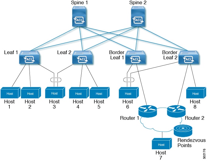
In this architecture, only the border leaf switches run the full Protocol Independent Multicast (PIM) protocol. Non-border leaf switches run PIM in a passive mode on the interfaces. They do not peer with any other PIM routers. The border leaf switches peer with other PIM routers connected to them over L3Outs and also with each other.

The following figure shows border leaf switch 1 and border leaf switch 2 connecting to router 1 and router 2 in the IPv4 multicast cloud. Each virtual routing and forwarding (VRF) instance in the fabric that requires IPv4 multicast routing will peer separately with external IPv4 multicast routers.

Figure 4. Overview of Multicast Cloud

Guidelines and Restrictions for Configuring Layer 3 Multicast

See the following guidelines and restrictions:

  • Custom QoS policy is not supported for Layer 3 multicast traffic sourced from outside the ACI fabric (received from L3Out).

  • Enabling PIMv4 (Protocol-Independent Multicast, version 4) and Advertise Host routes on a BD is not supported.

  • If the border leaf switches in your ACI fabric are running multicast and you disable multicast on the L3Out while you still have unicast reachability, you will experience traffic loss if the external peer is a Cisco Nexus 9000 switch. This impacts cases where traffic is destined towards the fabric (where the sources are outside the fabric but the receivers are inside the fabric) or transiting through the fabric (where the source and receivers are outside the fabric, but the fabric is transit).

  • If the (s, g) entry is installed on a border leaf switch, you might see drops in unicast traffic that comes from the fabric to this source outside the fabric when the following conditions are met:

    • Preferred group is used on the L3Out EPG

    • Unicast routing table for the source is using the default route 0.0.0.0/0

    This behavior is expected.

  • The Layer 3 multicast configuration is done at the VRF level so protocols function within the VRF and multicast is enabled in a VRF, and each multicast VRF can be turned on or off independently.

  • Once a VRF is enabled for multicast, the individual bridge domains (BDs) and L3 Outs under the enabled VRF can be enabled for multicast configuration. By default, multicast is disabled in all BDs and Layer 3 Outs.

  • Layer 3 multicast is not currently supported on VRFs that are configured with a shared L3 Out.

  • Any Source Multicast (ASM) and Source-Specific Multicast (SSM) are supported.

  • You can configure a maximum of four ranges for SSM multicast in the route map per VRF.

  • Bidirectional PIM, Rendezvous Point (RP) within the ACI fabric, and PIM IPv6 are currently not supported

  • IGMP snooping cannot be disabled on pervasive bridge domains with multicast routing enabled.

  • Multicast routers are not supported in pervasive bridge domains.

  • The Layer 3 multicast feature is supported on the following leaf switches:

    • EX models:

      • N9K-93108TC-EX

      • N9K-93180LC-EX

      • N9K-93180YC-EX

    • FX models:

      • N9K-93108TC-FX

      • N9K-93180YC-FX

      • N9K-C9348GC-FXP

    • FX2 models:

      • N9K-93240YC-FX2

      • N9K-C9336C-FX2

  • PIM is supported on Layer 3 Out routed interfaces and routed subinterfaces including Layer 3 port-channel interfaces. PIM is not supported on Layer 3 Out SVI interfaces.

  • Enabling PIM on an L3Out causes an implicit external network to be configured. This action results in the L3Out being deployed and protocols potentially coming up even if you have not defined an external network.

  • If the multicast source is connected to Leaf-A as an orphan port and you have an L3Out on Leaf-B, and Leaf-A and Leaf-B are in a vPC pair, the EPG encapsulation VLAN tied to the multicast source will need to be deployed on Leaf-B.

  • For Layer 3 multicast support, when the ingress leaf switch receives a packet from a source that is attached on a bridge domain, and the bridge domain is enabled for multicast routing, the ingress leaf switch sends only a routed VRF copy to the fabric (routed implies that the TTL is decremented by 1, and the source-mac is rewritten with a pervasive subnet MAC). The egress leaf switch also routes the packet into receivers in all the relevant bridge domains. Therefore, if a receiver is on the same bridge domain as the source, but on a different leaf switch than the source, that receiver continues to get a routed copy, although it is in the same bridge domain. This also applies if the source and receiver are on the same bridge domain and on the same leaf switch, if PIM is enabled on this bridge domain.

    For more information, see details about Layer 3 multicast support for multipod that leverages existing Layer 2 design, at the following link Adding Pods.

  • Starting with release 3.1(1), Layer 3 multicast is supported with FEX. Multicast sources or receivers that are connected to FEX ports are supported. For further details about how to add FEX in your testbed, see Configure a Fabric Extender with Application Centric Infrastructure at this URL: https://www.cisco.com/c/en/us/support/docs/cloud-systems-management/application-policy-infrastructure-controller-apic/200529-Configure-a-Fabric-Extender-with-Applica.html. For releases preceeding release 3.1(1), Layer 3 multicast is not supported with FEX. Multicast sources or receivers that are connected to FEX ports are not supported.

  • You cannot use a filter with inter-VRF multicast communication.


Note


Cisco ACI does not support IP fragmentation. Therefore, when you configure Layer 3 Outside (L3Out) connections to external routers, or Multi-Pod connections through an Inter-Pod Network (IPN), it is recommended that the interface MTU is set appropriately on both ends of a link. On some platforms, such as Cisco ACI, Cisco NX-OS, and Cisco IOS, the configurable MTU value does not take into account the Ethernet headers (matching IP MTU, and excluding the 14-18 Ethernet header size), while other platforms, such as IOS-XR, include the Ethernet header in the configured MTU value. A configured value of 9000 results in a max IP packet size of 9000 bytes in Cisco ACI, Cisco NX-OS, and Cisco IOS, but results in a max IP packet size of 8986 bytes for an IOS-XR untagged interface.

For the appropriate MTU values for each platform, see the relevant configuration guides.

We highly recommend that you test the MTU using CLI-based commands. For example, on the Cisco NX-OS CLI, use a command such as ping 1.1.1.1 df-bit packet-size 9000 source-interface ethernet 1/1.


Configuring Layer 3 Multicast Using REST API

Procedure


Step 1

Configure tenant, VRF, and enable multicast on VRF.

Example:

<fvTenant dn="uni/tn-PIM_Tenant" name="PIM_Tenant">
   <fvCtx knwMcastAct="permit" name="ctx1">
       <pimCtxP mtu="1500">
       </pimCtxP>
   </fvCtx>
  </fvTenant>

Step 2

Configure L3 Out and enable multicast (PIM, IGMP) on L3 Out.

Example:

<l3extOut enforceRtctrl="export" name="l3out-pim_l3out1">
       <l3extRsEctx tnFvCtxName="ctx1"/>
       <l3extLNodeP configIssues="" name="bLeaf-CTX1-101">
         <l3extRsNodeL3OutAtt rtrId="200.0.0.1" rtrIdLoopBack="yes" tDn="topology/pod-1/node-101"/>
         <l3extLIfP name="if-PIM_Tenant-CTX1" tag="yellow-green">
           <igmpIfP/>
           <pimIfP>
             <pimRsIfPol tDn="uni/tn-PIM_Tenant/pimifpol-pim_pol1"/>
           </pimIfP>
           <l3extRsPathL3OutAtt addr="131.1.1.1/24" ifInstT="l3-port" mode="regular" mtu="1500" tDn="topology/pod-1/paths-101/pathep-[eth1/46]"/>
         </l3extLIfP>
       </l3extLNodeP>
       <l3extRsL3DomAtt tDn="uni/l3dom-l3outDom"/>
       <l3extInstP name="l3out-PIM_Tenant-CTX1-1topo" >
       </l3extInstP>
       <pimExtP enabledAf="ipv4-mcast" name="pim"/>
     </l3extOut>

Step 3

Configure BD under tenant and enable multicast and IGMP on BD.

Example:

<fvTenant dn="uni/tn-PIM_Tenant" name="PIM_Tenant">
   <fvBD arpFlood="yes" mcastAllow="yes" multiDstPktAct="bd-flood" name="bd2" type="regular" unicastRoute="yes" unkMacUcastAct="flood" unkMcastAct="flood">
       <igmpIfP/>
       <fvRsBDToOut tnL3extOutName="l3out-pim_l3out1"/>
       <fvRsCtx tnFvCtxName="ctx1"/>
       <fvRsIgmpsn/>
       <fvSubnet ctrl="" ip="41.1.1.254/24" preferred="no" scope="private" virtual="no"/>
     </fvBD>
 </fvTenant>

Step 4

Configure IGMP policy and assign it to BD.

Example:

<fvTenant dn="uni/tn-PIM_Tenant" name="PIM_Tenant">
     <igmpIfPol grpTimeout="260" lastMbrCnt="2" lastMbrRespTime="1" name="igmp_pol" querierTimeout="255" queryIntvl="125" robustFac="2" rspIntvl="10" startQueryCnt="2" startQueryIntvl="125" ver="v2">
     </igmpIfPol>
      <fvBD arpFlood="yes" mcastAllow="yes" name="bd2">
      <igmpIfP>
         <igmpRsIfPol tDn="uni/tn-PIM_Tenant/igmpIfPol-igmp_pol"/>
       </igmpIfP>
      </fvBD>
 </fvTenant>

Step 5

Configure route map, PIM, and RP policy on VRF.

Example:

<fvTenant dn="uni/tn-PIM_Tenant" name="PIM_Tenant">
     <pimRouteMapPol name="rootMap">
       <pimRouteMapEntry action="permit" grp="224.0.0.0/4" order="10" rp="0.0.0.0" src="0.0.0.0/0"/>
     </pimRouteMapPol>
     <fvCtx knwMcastAct="permit" name="ctx1">
       <pimCtxP ctrl="" mtu="1500">
         <pimStaticRPPol>
           <pimStaticRPEntryPol rpIp="131.1.1.2">
             <pimRPGrpRangePol>
               <rtdmcRsFilterToRtMapPol tDn="uni/tn-PIM_Tenant/rtmap-rootMap"/>
             </pimRPGrpRangePol>
           </pimStaticRPEntryPol>
         </pimStaticRPPol>
       </pimCtxP>
   </fvCtx>
</fvTenant>

Step 6

Configure PIM interface policy and apply it on L3 Out.

Example:

<fvTenant dn="uni/tn-PIM_Tenant" name="PIM_Tenant">
  <pimIfPol authKey="" authT="none" ctrl="" drDelay="60" drPrio="1" helloItvl="30000" itvl="60" name="pim_pol1"/>
  <l3extOut enforceRtctrl="export" name="l3out-pim_l3out1" targetDscp="unspecified">
       <l3extRsEctx tnFvCtxName="ctx1"/>
       <l3extLNodeP  name="bLeaf-CTX1-101">
         <l3extRsNodeL3OutAtt rtrId="200.0.0.1" rtrIdLoopBack="yes" tDn="topology/pod-1/node-101"/>
         <l3extLIfP name="if-SIRI_VPC_src_recv-CTX1" tag="yellow-green">
           <pimIfP>
             <pimRsIfPol tDn="uni/tn-tn-PIM_Tenant/pimifpol-pim_pol1"/>
           </pimIfP>
         </l3extLIfP>
       </l3extLNodeP>
     </l3extOut>
 </fvTenant>

Pervasive Gateway

Common Pervasive Gateway

Multiple ACI fabrics can be configured with an IPv4 common gateway on a per bridge domain basis. Doing so enables moving one or more virtual machines (VM) or conventional hosts across the fabrics while the host retains its IP address. VM host moves across fabrics can be done automatically by the VM hypervisor. The ACI fabrics can be co-located, or provisioned across multiple sites. The Layer 2 connection between the ACI fabrics can be a local link, or can be across a routed WAN link. The following figure illustrates the basic common pervasive gateway topology.
Figure 5. ACI Multi-Fabric Common Pervasive Gateway


The per-bridge domain common pervasive gateway configuration requirements are as follows:

  • The bridge domain MAC (mac) values for each fabric must be unique.

    Note


    The default bridge domain MAC (mac) address values are the same for all ACI fabrics. The common pervasive gateway requires an administrator to configure the bridge domain MAC (mac) values to be unique for each ACI fabric.


  • The bridge domain virtual MAC (vmac) address and the subnet virtual IP address must be the same across all ACI fabrics for that bridge domain. Multiple bridge domains can be configured to communicate across connected ACI fabrics. The virtual MAC address and the virtual IP address can be shared across bridge domains.

Configuring Common Pervasive Gateway Using the REST API

Before you begin

  • The tenant, VRF, and bridge domain are created.

Procedure


Configure common pervasive gateway.

In the following example REST API XML, the bolded text is relevant to configuring a common pervasive gateway.

Example:


<?xml version="1.0" encoding="UTF-8"?>
<!-- api/policymgr/mo/.xml -->
<polUni>
  <fvTenant name="test">
    <fvCtx name="test"/>

    <fvBD name="test" vmac="12:34:56:78:9a:bc">
      <fvRsCtx tnFvCtxName="test"/>
      <!-- Primary address -->
      <fvSubnet ip="192.168.15.254/24" preferred="yes"/>
      <!-- Virtual address -->
      <fvSubnet ip="192.168.15.1/24" virtual="yes"/>
    </fvBD>

    <fvAp name="test">
      <fvAEPg name="web">
        <fvRsBd tnFvBDName="test"/>
        <fvRsPathAtt tDn="topology/pod-1/paths-101/pathep-[eth1/3]" encap="vlan-1002"/>
      </fvAEPg>
    </fvAp>
  </fvTenant>
</polUni>

Explicit Prefix Lists

About Explicit Prefix List Support for Route Maps/Profile

In Cisco APIC, for public bridge domain (BD) subnets and external transit networks, inbound and outbound route controls are provided through an explicit prefix list. Inbound and outbound route control for Layer 3 Out is managed by the route map/profile (rtctrlProfile). The route map/profile policy supports a fully controllable prefix list for Layer 3 Out in the Cisco ACI fabric.

The subnets in the prefix list can represent the bridge domain public subnets or external networks. Explicit prefix list presents an alternate method and can be used instead of the following:

  • Advertising BD subnets through BD to Layer 3 Out relation.


    Note


    The subnet in the BD must be marked public for the subnet to be advertised out.


  • Specifying a subnet in the l3extInstP with export/import route control for advertising transit and external networks.

Explicit prefix list is defined through a new match type that is called match route destination (rtctrlMatchRtDest). An example usage is provided in the API example that follows.

Figure 6. External Policy Model of API

Additional information about match rules, set rules when using explicit prefix list are as follows:

Match Rules

  • Under the tenant (fvTenant), you can create match profiles (rtctrlSubjP) for route map filtering. Each match profile can contain one or more match rules. Match rule supports multiple match types. Prior to Cisco APIC release 2.1(x), match types supported were explicit prefix list and community list.

    Starting with Cisco APIC release 2.1(x), explicit prefix match or match route destination (rtctrlMatchRtDest) is supported.

    Match prefix list (rtctrlMatchRtDest) supports one or more subnets with an optional aggregate flag. Aggregate flags are used for allowing prefix matches with multiple masks starting with the mask mentioned in the configuration till the maximum mask allowed for the address family of the prefix . This is the equivalent of the "le " option in the prefix-list in NX-OS software (example, 10.0.0.0/8 le 32).

    The prefix list can be used for covering the following cases:

    • Allow all ( 0.0.0.0/0 with aggregate flag, equivalent of 0.0.0.0/0 le 32 )

    • One or more of specific prefixes (example: 10.1.1.0/24)

    • One or more of prefixes with aggregate flag (example, equivalent of 10.1.1.0/24 le 32).


    Note


    When a route map with a match prefix “0.0.0.0/0 with aggregate flag” is used under an L3Out EPG in the export direction, the rule is applied only for redistribution from dynamic routing protocols. Therefore, the rule is not applied to the following (in routing protocol such as OSPF or EIGRP):

    • Bridge domain (BD) subnets

    • Directly connected subnets on the border leaf switch

    • Static routes defined on the L3Out


  • The explicit prefix match rules can contain one or more subnets, and these subnets can be bridge domain public subnets or external networks. Subnets can also be aggregated up to the maximum subnet mask (/32 for IPv4 and /128 for IPv6).

  • When multiple match rules of different types are present (such as match community and explicit prefix match), the match rule is allowed only when the match statements of all individual match types match. This is the equivalent of the AND filter. The explicit prefix match is contained by the subject profile (rtctrlSubjP) and will form a logical AND if other match rules are present under the subject profile.

  • Within a given match type (such as match prefix list), at least one of the match rules statement must match. Multiple explicit prefix match (rtctrlMatchRtDest) can be defined under the same subject profile (rtctrlSubjP) which will form a logical OR.

Set Rules

  • Set policies must be created to define set rules that are carried with the explicit prefixes such as set community, set tag.

Guidelines and Limitations

  • You must choose one of the following two methods to configure your route maps. If you use both methods, it will result in double entries and undefined route maps.

    • Add routes under the bridge domain (BD) and configure a BD to Layer 3 Outside relation

    • Configure the match prefix under rtctrlSubjP match profiles.

  • Starting 2.3(x), deny-static implicit entry has been removed from Export Route Map. The user needs to configure explicitly the permit and deny entries required to control the export of static routes.

  • Route-map per peer in an L3Oout is not supported. Route-map can only be applied on L3Out as a whole.

    Following are possible workarounds to this issue:

    • Block the prefix from being advertised from the other side of the neighbor.

    • Block the prefix on the route-map on the existing L3Out where you don't want to learn the prefix, and move the neighbor to another L3Out where you want to learn the prefix and create a separate route-map.

  • Creating route-maps using a mixture of GUI and API commands is not supported. As a possible workaround, you can create a route-map different from the default route-map using the GUI, but the route-map created through the GUI on an L3Out cannot be applied to per-peer.

About Route Map/Profile

The route profile is a logical policy that defines an ordered set (rtctrlCtxP) of logical match action rules with associated set action rules. The route profile is the logical abstract of a route map. Multiple route profiles can be merged into a single route map. A route profile can be one of the following types:

  • Match Prefix and Routing Policy: Pervasive subnets (fvSubnet) and external subnets (l3extSubnet) are combined with a route profile and merged into a single route map (or route map entry). Match Prefix and Routing Policy is the default value.

  • Match Routing Policy Only: The route profile is the only source of information to generate a route map, and it will overwrite other policy attributes.


Note


When explicit prefix list is used, the type of the route profile should be set to "match routing policy only".


After the match and set profiles are defined, the route map must be created in the Layer 3 Out. Route maps can be created using one of the following methods:

  • Create a "default-export" route map for export route control, and a "default-import" route map for import route control.

  • Create other route maps (not named default-export or default-import) and setup the relation from one or more l3extInstPs or subnets under the l3extInstP.

  • In either case, match the route map on explicit prefix list by pointing to the rtctrlSubjP within the route map.

In the export and import route map, the set and match rules are grouped together along with the relative sequence across the groups (rtctrlCtxP). Additionally, under each group of match and set statements (rtctrlCtxP) the relation to one or more match profiles are available (rtctrlSubjP).

Any protocol enabled on Layer 3 Out (for example BGP protocol), will use the export and import route map for route filtering.

Aggregation Support for Explicit Prefix List

Each prefix (rtctrlMatchRtDest) in the match prefixes list can be aggregated to support multiple subnets matching with one prefix list entry..

Aggregated prefixes and BD private subnets: Although subnets in the explicit prefix list match may match the BD private subnets using aggregated or exact match, private subnets will not be advertised through the routing protocol using the explicit prefix list. The scope of the BD subnet must be set to "public" for the explicit prefix list feature to advertise the BD subnets.

Configuring Route Map/Profile with Explicit Prefix List Using REST API

Before you begin

  • Tenant and VRF must be configured.

Procedure


Configure the route map/profile using explicit prefix list.

Example:

<?xml version="1.0" encoding="UTF-8"?>
<fvTenant name="PM" status="">
   <rtctrlAttrP name="set_dest">
      <rtctrlSetComm community="regular:as2-nn2:5:24" />
   </rtctrlAttrP>
   <rtctrlSubjP name="allow_dest">
      <rtctrlMatchRtDest ip="192.169.0.0/24" />
      <rtctrlMatchCommTerm name="term1">
         <rtctrlMatchCommFactor community="regular:as2-nn2:5:24" status="" />
         <rtctrlMatchCommFactor community="regular:as2-nn2:5:25" status="" />
      </rtctrlMatchCommTerm>
      <rtctrlMatchCommRegexTerm commType="regular" regex="200:*" status="" />
   </rtctrlSubjP>
   <rtctrlSubjP name="deny_dest">
      <rtctrlMatchRtDest ip="192.168.0.0/24" />
   </rtctrlSubjP>
   <fvCtx name="ctx" />
   <l3extOut name="L3Out_1" enforceRtctrl="import,export" status="">
      <l3extRsEctx tnFvCtxName="ctx" />
      <l3extLNodeP name="bLeaf">
         <l3extRsNodeL3OutAtt tDn="topology/pod-1/node-101" rtrId="1.2.3.4" />
         <l3extLIfP name="portIf">
            <l3extRsPathL3OutAtt tDn="topology/pod-1/paths-101/pathep-[eth1/25]" ifInstT="sub-interface" encap="vlan-1503" addr="10.11.12.11/24" />
            <ospfIfP />
         </l3extLIfP>
         <bgpPeerP addr="5.16.57.18/32" ctrl="send-com" />
         <bgpPeerP addr="6.16.57.18/32" ctrl="send-com" />
      </l3extLNodeP>
      <bgpExtP />
      <ospfExtP areaId="0.0.0.59" areaType="nssa" status="" />
      <l3extInstP name="l3extInstP_1" status="">
         <l3extSubnet ip="17.11.1.11/24" scope="import-security" />
      </l3extInstP>
      <rtctrlProfile name="default-export" type="global" status="">
         <rtctrlCtxP name="ctx_deny" action="deny" order="1">
            <rtctrlRsCtxPToSubjP tnRtctrlSubjPName="deny_dest" status="" />
         </rtctrlCtxP>
         <rtctrlCtxP name="ctx_allow" order="2">
            <rtctrlRsCtxPToSubjP tnRtctrlSubjPName="allow_dest" status="" />
         </rtctrlCtxP>
         <rtctrlScope name="scope" status="">
            <rtctrlRsScopeToAttrP tnRtctrlAttrPName="set_dest" status="" />
         </rtctrlScope>
      </rtctrlProfile>
   </l3extOut>
   <fvBD name="testBD">
      <fvRsBDToOut tnL3extOutName="L3Out_1" />
      <fvRsCtx tnFvCtxName="ctx" />
      <fvSubnet ip="40.1.1.12/24" scope="public" />
      <fvSubnet ip="40.1.1.2/24" scope="private" />
      <fvSubnet ip="2003::4/64" scope="public" />
   </fvBD>
</fvTenant>

IP Address Aging Tracking

Overview

The IP Aging policy tracks and ages unused IP addresses on an endpoint. Tracking is performed using the endpoint retention policy configured for the bridge domain to send ARP requests (for IPv4) and neighbor solicitations (for IPv6) at 75% of the local endpoint aging interval. When no response is received from an IP address, that IP address is aged out.

This document explains how to configure the IP Aging policy.

Configuring IP Aging Using the REST API

This section explains how to enable and disable the IP aging policy using the REST API.

Procedure


Step 1

To enable the IP aging policy:

Example:

<epIpAgingP adminSt="enabled" descr="" dn="uni/infra/ipAgingP-default" name="default" ownerKey="" ownerTag=""/>

Step 2

To disable the IP aging policy:

Example:

<epIpAgingP adminSt="disabled" descr="" dn="uni/infra/ipAgingP-default" name="default" ownerKey="" ownerTag=""/>

What to do next

To specify the interval used for tracking IP addresses on endpoints, create an Endpoint Retention policy by sending a post with XML such as the following example:

<fvEpRetPol bounceAgeIntvl="630" bounceTrig="protocol" 
holdIntvl="350" lcOwn="local" localEpAgeIntvl="900" moveFreq="256" 
name="EndpointPol1" remoteEpAgeIntvl="350"/>

Route Summarization

Configuring Route Summarization for BGP, OSPF, and EIGRP Using the REST API

Procedure


Step 1

Configure BGP route summarization using the REST API as follows:

Example:

   
<fvTenant name="common">
           <fvCtx name="vrf1"/>
   <bgpRtSummPol name=“bgp_rt_summ” cntrl=‘as-set'/>
   <l3extOut name=“l3_ext_pol” >
             <l3extLNodeP name="bLeaf">
                <l3extRsNodeL3OutAtt tDn="topology/pod-1/node-101" rtrId=“20.10.1.1"/>
              <l3extLIfP name='portIf'>
              <l3extRsPathL3OutAtt tDn="topology/pod-1/paths-101/pathep-[eth1/31]" ifInstT=‘l3-port’ addr=“10.20.1.3/24/>
              </l3extLIfP>
           </l3extLNodeP>
         <bgpExtP />
           <l3extInstP name="InstP" >
         <l3extSubnet ip="10.0.0.0/8" scope=“export-rtctrl">
           <l3extRsSubnetToRtSumm tDn=“uni/tn-common/bgprtsum-bgp_rt_summ”/>
           <l3extRsSubnetToProfile tnRtctrlProfileName=“rtprof"/>
         </l3extSubnet>
       </l3extInstP>
       <l3extRsEctx tnFvCtxName=“vrf1”/>
   </l3extOut>
</fvTenant>

Step 2

Configure OSPF inter-area and external summarization using the following REST API:

Example:


<?xml version="1.0" encoding="utf-8"?>
<fvTenant name="t20">
  <!--Ospf Inter External route summarization Policy-->
  <ospfRtSummPol cost="unspecified" interAreaEnabled="no" name="ospfext"/>
  <!--Ospf Inter Area route summarization Policy-->
  <ospfRtSummPol cost="16777215" interAreaEnabled="yes" name="interArea"/>
  <fvCtx name="ctx0" pcEnfDir="ingress" pcEnfPref="enforced"/>
  <!-- L3OUT backbone Area-->
  <l3extOut enforceRtctrl="export" name="l3_1" ownerKey="" ownerTag="" targetDscp="unspecified">
    <l3extRsEctx tnFvCtxName="ctx0"/>
    <l3extLNodeP name="node-101">
      <l3extRsNodeL3OutAtt rtrId="20.1.3.2" rtrIdLoopBack="no" tDn="topology/pod-1/node-101"/>
      <l3extLIfP name="intf-1">
        <l3extRsPathL3OutAtt addr="20.1.5.2/24" encap="vlan-1001" ifInstT="sub-interface" tDn="topology/pod-1/paths-101/pathep-[eth1/33]"/>
      </l3extLIfP>
    </l3extLNodeP>
    <l3extInstP name="l3InstP1">
      <fvRsProv tnVzBrCPName="default"/>
      <!--Ospf External Area route summarization-->
      <l3extSubnet aggregate="" ip="193.0.0.0/8" name="" scope="export-rtctrl">
        <l3extRsSubnetToRtSumm tDn="uni/tn-t20/ospfrtsumm-ospfext"/>
      </l3extSubnet>
    </l3extInstP>
    <ospfExtP areaCost="1" areaCtrl="redistribute,summary" areaId="backbone" areaType="regular"/>
  </l3extOut>
  <!-- L3OUT Regular Area-->
  <l3extOut enforceRtctrl="export" name="l3_2">
    <l3extRsEctx tnFvCtxName="ctx0"/>
    <l3extLNodeP name="node-101">
      <l3extRsNodeL3OutAtt rtrId="20.1.3.2" rtrIdLoopBack="no" tDn="topology/pod-1/node-101"/>
      <l3extLIfP name="intf-2">
        <l3extRsPathL3OutAtt addr="20.1.2.2/24" encap="vlan-1014" ifInstT="sub-interface" tDn="topology/pod-1/paths-101/pathep-[eth1/11]"/>
      </l3extLIfP>
    </l3extLNodeP>
    <l3extInstP matchT="AtleastOne" name="l3InstP2">
      <fvRsCons tnVzBrCPName="default"/>
      <!--Ospf Inter Area route summarization-->
      <l3extSubnet aggregate="" ip="197.0.0.0/8" name="" scope="export-rtctrl">
        <l3extRsSubnetToRtSumm tDn="uni/tn-t20/ospfrtsumm-interArea"/>
      </l3extSubnet>
    </l3extInstP>
    <ospfExtP areaCost="1" areaCtrl="redistribute,summary" areaId="0.0.0.57" areaType="regular"/>
  </l3extOut>
</fvTenant>

Step 3

Configure EIGRP summarization using the following REST API:

Example:

   
<fvTenant name="exampleCorp"> 
  <l3extOut name="out1">
    <l3extInstP  name="eigrpSummInstp" >
      <l3extSubnet aggregate="" descr="" ip="197.0.0.0/8" name="" scope="export-rtctrl">
        <l3extRsSubnetToRtSumm/>
      </l3extSubnet>
    </l3extInstP>
  </l3extOut>
  <eigrpRtSummPol name="pol1" />

Note


There is no route summarization policy to be configured for EIGRP. The only configuration needed for enabling EIGRP summarization is the summary subnet under the InstP.


Route Controls

About Configuring a Routing Control Protocol Using Import and Export Controls

This topic provides a typical example that shows how to configure a routing control protocol using import and export controls. It assumes that you have configured Layer 3 outside network connections with BGP. You can also perform these tasks for a Layer 3 outside network configured with OSPF.


Note


Cisco ACI does not support IP fragmentation. Therefore, when you configure Layer 3 Outside (L3Out) connections to external routers, or Multi-Pod connections through an Inter-Pod Network (IPN), it is recommended that the interface MTU is set appropriately on both ends of a link. On some platforms, such as Cisco ACI, Cisco NX-OS, and Cisco IOS, the configurable MTU value does not take into account the Ethernet headers (matching IP MTU, and excluding the 14-18 Ethernet header size), while other platforms, such as IOS-XR, include the Ethernet header in the configured MTU value. A configured value of 9000 results in a max IP packet size of 9000 bytes in Cisco ACI, Cisco NX-OS, and Cisco IOS, but results in a max IP packet size of 8986 bytes for an IOS-XR untagged interface.

For the appropriate MTU values for each platform, see the relevant configuration guides.

We highly recommend that you test the MTU using CLI-based commands. For example, on the Cisco NX-OS CLI, use a command such as ping 1.1.1.1 df-bit packet-size 9000 source-interface ethernet 1/1.


Configuring a Route Control Protocol to Use Import and Export Controls, With the REST API

This example assumes that you have configured the Layer 3 outside network connections using BGP. It is also possible to perform these tasks for a network using OSPF.

Before you begin

  • The tenant, private network, and bridge domain are created.

  • The Layer 3 outside tenant network is configured.

Procedure


Configure the route control protocol using import and export controls.

Example:


<l3extOut descr="" dn="uni/tn-Ten_ND/out-L3Out1" enforceRtctrl="export" name="L3Out1" ownerKey="" ownerTag="" targetDscp="unspecified">
        <l3extLNodeP descr="" name="LNodeP1" ownerKey="" ownerTag="" tag="yellow-green" targetDscp="unspecified">
            <l3extRsNodeL3OutAtt rtrId="1.2.3.4" rtrIdLoopBack="yes" tDn="topology/pod-1/node-101">
                <l3extLoopBackIfP addr="2000::3" descr="" name=""/>
            </l3extRsNodeL3OutAtt>
            <l3extLIfP descr="" name="IFP1" ownerKey="" ownerTag="" tag="yellow-green">
                <ospfIfP authKeyId="1" authType="none" descr="" name="">
                    <ospfRsIfPol tnOspfIfPolName=""/>
                </ospfIfP>
                <l3extRsNdIfPol tnNdIfPolName=""/>
                <l3extRsPathL3OutAtt addr="10.11.12.10/24" descr="" encap="unknown" ifInstT="l3-port" 
llAddr="::" mac="00:22:BD:F8:19:FF" mtu="1500" tDn="topology/pod-1/paths-101/pathep-[eth1/17]" targetDscp="unspecified"/>
            </l3extLIfP>
        </l3extLNodeP>
        <l3extRsEctx tnFvCtxName="PVN1"/>
        <l3extInstP descr="" matchT="AtleastOne" name="InstP1" prio="unspecified" targetDscp="unspecified">
            <fvRsCustQosPol tnQosCustomPolName=""/>
            <l3extSubnet aggregate="" descr="" ip="192.168.1.0/24" name="" scope=""/>
        </l3extInstP>
        <ospfExtP areaCost="1" areaCtrl="redistribute,summary" areaId="0.0.0.1" areaType="nssa" descr=""/>
        <rtctrlProfile descr="" name="default-export" ownerKey="" ownerTag="">
            <rtctrlCtxP descr="" name="routecontrolpvtnw" order="3">
                <rtctrlScope descr="" name="">
                    <rtctrlRsScopeToAttrP tnRtctrlAttrPName="actionruleprofile2"/>
                </rtctrlScope>
            </rtctrlCtxP>
        </rtctrlProfile>
    </l3extOut>

Layer 3 to Layer 3 Out Inter-VRF Leaking

Layer 3 Out to Layer 3 Out Inter-VRF Leaking

Starting with Cisco APIC release 2.2(2e) , when there are two Layer 3 Outs in two different VRFs, inter-VRF leaking is supported.

For this feature to work, the following conditions must be satisfied:

  • A contract between the two Layer 3 Outs is required.

  • Routes of connected and transit subnets for a Layer 3 Out are leaked by enforcing contracts (L3Out-L3Out as well as L3Out-EPG) and without leaking the dynamic or static routes between VRFs.

  • Dynamic or static routes are leaked for a Layer 3 Out by enforcing contracts (L3Out-L3Out as well as L3Out-EPG) and without advertising directly connected or transit routes between VRFs.

  • Shared Layer 3 Outs in different VRFs can communicate with each other.

  • There is no associated L3Out required for the bridge domain. When an Inter-VRF shared L3Out is used, it is not necessary to associate the user tenant bridge domains with the L3Out in tenant common. If you had a tenant-specific L3Out, it would still be associated to your bridge domains in your respective tenants.

  • Two Layer 3 Outs can be in two different VRFs, and they can successfully exchange routes.

  • This enhancement is similar to the Application EPG to Layer 3 Out inter-VRF communications. The only difference is that instead of an Application EPG there is another Layer 3 Out. Therefore, in this case, the contract is between two Layer 3 Outs.

In the following figure, there are two Layer 3 Outs with a shared subnet. There is a contract between the Layer 3 external instance profile (l3extInstP) in both the VRFs. In this case, the Shared Layer 3 Out for VRF1 can communicate with the Shared Layer 3 Out for VRF2.

Figure 7. Shared Layer 3 Outs Communicating Between Two VRFs

Configuring Two Shared Layer 3 Outs in Two VRFs Using REST API

The following REST API configuration example that displays how two shared Layer 3 Outs in two VRFs communicate.

Procedure


Step 1

Configure the provider Layer 3 Out.

Example:

<tenant name=“t1_provider”>
<fvCtx name=“VRF1">
<l3extOut name="T0-o1-L3OUT-1">
                <l3extRsEctx tnFvCtxName="o1"/>
                <ospfExtP areaId='60'/>
                <l3extInstP name="l3extInstP-1">
                <fvRsProv tnVzBrCPName="vzBrCP-1">
                </fvRsProv>
                <l3extSubnet ip="192.168.2.0/24" scope=“shared-rtctrl, shared-security" aggregate=""/>
                </l3extInstP>
</l3extOut>
</tenant>

Step 2

Configure the consumer Layer 3 Out.

Example:

<tenant name=“t1_consumer”>
<fvCtx name=“VRF2">
<l3extOut name="T0-o1-L3OUT-1">
                <l3extRsEctx tnFvCtxName="o1"/>
                <ospfExtP areaId=‘70'/>
                <l3extInstP name="l3extInstP-2">
                <fvRsCons tnVzBrCPName="vzBrCP-1">
                </fvRsCons>
                <l3extSubnet ip="199.16.2.0/24" scope=“shared-rtctrl, shared-security"          aggregate=""/>
                </l3extInstP>
</l3extOut>
</tenant>

Overview Interleak Redistribution for MP-BGP

This topic provides how to configure an interleak redistribution in the Cisco Application Centric Infrastructure (ACI) fabric using Cisco Application Policy Infrastructure Controller (APIC).

In Cisco ACI, a border leaf node on which Layer 3 Outsides (L3Outs) are deployed redistributes L3Out routes to the BGP IPv4/IPv6 address family and then to the MP-BGP VPNv4/VPNv6 address family along with the VRF information so that L3Out routes are distributed from a border leaf node to other leaf nodes through the spine nodes. Interleak redistribution in the Cisco ACI fabric refers to this redistribution of L3Out routes to the BGP IPv4/IPv6 address family. By default, interleak happens for all L3Out routes, such as routes learned through dynamic routing protocols, static routes, and directly-connected subnets of L3Out interfaces, except for routes learned through BGP. Routes learned through BGP are already in the BGP IPv4/IPv6 table and are ready to be exported to MP-BGP VPNv4/VPNv6 without interleak.

Interleak redistribution allows users to apply a route-map to redistribute L3Out routes selectively into BGP to control which routes should be visible to other leaf nodes, or to set some attributes to the routes, such as BGP community, preference, metric, and so on. This redistribution enables selective transit routing to be performed on another border leaf node based on the attributes set by the ingress border leaf node or so that other leaf nodes can prefer routes from one border leaf node to another.

Applying a route map to interleak redistribution from OSPF and EIGRP routes has been available in earlier releases.

Configuring Interleak of External Routes Using the REST API

Before you begin

  • The tenant, VRF, and bridge domain are created.

  • The external routed domain is created.

Procedure


Configure an interleak of external routes:

Example:

    
<l3extOut descr="" enforceRtctrl="export" name="out1" ownerKey="" ownerTag="" targetDscp="unspecified">
      <l3extLNodeP configIssues="" descr="" name="Lnodep1" ownerKey="" ownerTag="" tag="yellow-green" targetDscp="unspecified">
        <l3extRsNodeL3OutAtt rtrId="1.2.3.4" rtrIdLoopBack="yes" tDn="topology/pod-1/node-101"/>
        <l3extLIfP descr="" name="lifp1" ownerKey="" ownerTag="" tag="yellow-green">
          <ospfIfP authKeyId="1" authType="none" descr="" name="">
            <ospfRsIfPol tnOspfIfPolName=""/>
          </ospfIfP>
          <l3extRsNdIfPol tnNdIfPolName=""/>
          <l3extRsIngressQosDppPol tnQosDppPolName=""/>
          <l3extRsEgressQosDppPol tnQosDppPolName=""/>
          <l3extRsPathL3OutAtt addr="12.12.7.16/24" descr="" encap="unknown" encapScope="local" ifInstT="l3-port" llAddr="::" mac="00:22:BD:F8:19:FF" mode="regular" mtu="inherit" tDn="topology/pod-1/paths-101/pathep-[eth1/11]" targetDscp="unspecified"/>
        </l3extLIfP>
      </l3extLNodeP>
      <l3extRsEctx tnFvCtxName="ctx1"/>
      <l3extRsInterleakPol tnRtctrlProfileName="interleak"/>
      <l3extRsL3DomAtt tDn="uni/l3dom-Domain"/>
      <l3extInstP descr="" matchT="AtleastOne" name="InstP1" prio="unspecified" targetDscp="unspecified">
        <fvRsCustQosPol tnQosCustomPolName=""/>
        <l3extSubnet aggregate="" descr="" ip="14.15.16.0/24" name="" scope="export-rtctrl,import-security"/>
      </l3extInstP>
      <ospfExtP areaCost="1" areaCtrl="redistribute,summary" areaId="0.0.0.1" areaType="nssa" descr=""/>
    </l3extOut>

SVI External Encapsulation Scope

About SVI External Encapsulation Scope

In the context of a Layer 3 Out configuration, a switch virtual interfaces (SVI), is configured to provide connectivity between the ACI leaf switch and a router.

By default, when a single Layer 3 Out is configured with SVI interfaces, the VLAN encapsulation spans multiple nodes within the fabric. This happens because the ACI fabric configures the same bridge domain (VXLAN VNI) across all the nodes in the fabric where the Layer 3 Out SVI is deployed as long as all SVI interfaces use the same external encapsulation (SVI) as shown in the figure.

However, when different Layer 3 Outs are deployed, the ACI fabric uses different bridge domains even if they use the same external encapsulation (SVI) as shown in the figure:

Figure 8. Local Scope Encapsulation and One Layer 3 Out
Figure 9. Local Scope Encapsulation and Two Layer 3 Outs

Starting with Cisco APIC release 2.3, it is now possible to choose the behavior when deploying two (or more) Layer 3 Outs using the same external encapsulation (SVI).

The encapsulation scope can now be configured as Local or VRF:

  • Local scope (default): The example behavior is displayed in the figure titled Local Scope Encapsulation and Two Layer 3 Outs.

  • VRF scope: The ACI fabric configures the same bridge domain (VXLAN VNI) across all the nodes and Layer 3 Out where the same external encapsulation (SVI) is deployed. See the example in the figure titled VRF Scope Encapsulation and Two Layer 3 Outs.

Figure 10. VRF Scope Encapsulation and Two Layer 3 Outs

Encapsulation Scope Syntax

The options for configuring the scope of the encapsulation used for the Layer 3 Out profile are as follows:

  • Ctx—The same external SVI in all Layer 3 Outs in the same VRF for a given VLAN encapsulation. This is a global value.

  • Local —A unique external SVI per Layer 3 Out. This is the default value.

The mapping among the CLI, API, and GUI syntax is as follows:

Table 1. Encapsulation Scope Syntax

CLI

API

GUI

l3out

local

Local

vrf

ctx

VRF


Note


The CLI commands to configure encapsulation scope are only supported when the VRF is configured through a named Layer 3 Out configuration.


Configuring SVI Interface Encapsulation Scope Using the REST API

Before you begin

The interface selector is configured.

Procedure


Configure the SVI interface encapsulation scope.

Example:


<?xml version="1.0" encoding="UTF-8"?>
<!-- /api/node/mo/.xml -->
<polUni>
	<fvTenant name="coke">
		<l3extOut descr="" dn="uni/tn-coke/out-l3out1" enforceRtctrl="export" name="l3out1" nameAlias="" ownerKey="" ownerTag="" targetDscp="unspecified">
			<l3extRsL3DomAtt tDn="uni/l3dom-Dom1"/>
			<l3extRsEctx tnFvCtxName="vrf0"/>
			<l3extLNodeP configIssues="" descr="" name="__ui_node_101" nameAlias="" ownerKey="" ownerTag="" tag="yellow-green" targetDscp="unspecified">
				<l3extRsNodeL3OutAtt rtrId="1.1.1.1" rtrIdLoopBack="no" tDn="topology/pod-1/node-101"/>
				<l3extLIfP descr="" name="int1_11" nameAlias="" ownerKey="" ownerTag="" tag="yellow-green">
					<l3extRsPathL3OutAtt addr="1.2.3.4/24" descr="" encap="vlan-2001" encapScope="ctx" ifInstT="ext-svi" llAddr="0.0.0.0" mac="00:22:BD:F8:19:FF" mode="regular" mtu="inherit" tDn="topology/pod-1/paths-101/pathep-[eth1/5]" targetDscp="unspecified"/>
					<l3extRsNdIfPol tnNdIfPolName=""/>
					<l3extRsIngressQosDppPol tnQosDppPolName=""/>
					<l3extRsEgressQosDppPol tnQosDppPolName=""/>
				</l3extLIfP>
			</l3extLNodeP>
			<l3extInstP descr="" matchT="AtleastOne" name="epg1" nameAlias="" prefGrMemb="exclude" prio="unspecified" targetDscp="unspecified">
				<l3extSubnet aggregate="" descr="" ip="101.10.10.1/24" name="" nameAlias="" scope="import-security"/>
				<fvRsCustQosPol tnQosCustomPolName=""/>
			</l3extInstP>
		</l3extOut>
	</fvTenant>
</polUni>

SVI Auto State

About SVI Auto State


Note


This feature is available in the APIC Release 2.2(3x) release and going forward with APIC Release 3.1(1). It is not supported in APIC Release 3.0(x).


The Switch Virtual Interface (SVI) represents a logical interface between the bridging function and the routing function of a VLAN in the device. SVI can have members that are physical ports, direct port channels, or virtual port channels. The SVI logical interface is associated with VLANs, and the VLANs have port membership.

The SVI state does not depend on the members. The default auto state behavior for SVI in Cisco APIC is that it remains in the up state when the auto state value is disabled. This means that the SVI remains active even if no interfaces are operational in the corresponding VLAN/s.

If the SVI auto state value is changed to enabled, then it depends on the port members in the associated VLANs. When a VLAN interface has multiple ports in the VLAN, the SVI goes to the down state when all the ports in the VLAN go down.

Table 2. SVI Auto State

SVI Auto State

Description of SVI State

Disabled

SVI remains in the up state even if no interfaces are operational in the corresponding VLAN/s.

Disabled is the default SVI auto state value.

Enabled

SVI depends on the port members in the associated VLANs. When a VLAN interface contains multiple ports, the SVI goes into the down state when all the ports in the VLAN go down.

Guidelines and Limitations for SVI Auto State Behavior

Read the following guidelines:

  • When you enable or disable the auto state behavior for SVI, you configure the auto state behavior per SVI. There is no global command.

Configuring SVI Auto State Using the REST API

Before you begin

  • The tenant and VRF configured.

  • A Layer 3 Out is configured and a logical node profile and a logical interface profile under the Layer 3 Out is configured.

Procedure


Enable the SVI auto state value.

Example:


<fvTenant name="t1" >
   <l3extOut name="out1">
      <l3extLNodeP name="__ui_node_101" >
         <l3extLIfP descr="" name="__ui_eth1_10_vlan_99_af_ipv4" >
            <l3extRsPathL3OutAtt addr="19.1.1.1/24" autostate="enabled" descr="" encap="vlan-100" encapScope="local" ifInstT="ext-svi" llAddr="::" mac="00:22:BD:F8:19:FF" mode="regular" mtu="inherit" tDn="topology/pod-1/paths-101/pathep-[eth1/10]" targetDscp="unspecified" />
         </l3extLIfP>
      </l3extLNodeP>
   </l3extOut>
</fvTenant>

To disable the autostate, you must change the value to disabled in the above example. For example, autostate="disabled".


Routing Protocols

BGP and BFD

Guidelines for Configuring a BGP Layer 3 Outside Network Connection

When configuring a BGP external routed network, follow these guidelines:

  • The BGP direct route export behavior changed after release 3.2(1), where ACI does not evaluate the originating route type (such as static, direct, and so on) when matching export route map clauses. As a result, the "match direct" deny clause that is always included in the outbound neighbor route map no longer matches direct routes, and direct routes are now advertised based on whether or not a user-defined route map clause matches.

    Therefore, the direct route must be advertised explicitly through the route map. Failure to do so will implicitly deny the direct route being advertised.

  • The AS override option in the BGP Controls field in the BGP Peer Connectivity Profile for an L3Out was introduced in release 3.1(2). It allows Cisco Application Centric Infrastructure (ACI) to overwrite a remote AS in the AS_PATH with ACI BGP AS. In Cisco ACI, it is typically used when performing transit routing from an eBGP L3Out to another eBGP L3Out with the same AS number.

    However, an issue arises if you enable the AS override option when the eBGP neighbor has a different AS number. In this situation, strip the peer-as from the AS_PATH when reflecting it to a peer.

  • The Local-AS Number option in the BGP Peer Connectivity Profile is supported only for eBGP peering. This enables Cisco ACI border leaf switches to appear to be a member of another AS in addition to its real AS assigned to the fabric MP-BGP Route Reflector Policy. This means that the local AS number must be different from the real AS number of the Cisco ACI fabric. When this feature is configured, Cisco ACI border leaf switches prepend the local AS number to the AS_PATH of the incoming updates and append the same to the AS_PATH of the outgoing updates. Prepending of the local AS number to the incoming updates can be disabled by the no-prepend setting in the Local-AS Number Config. The no-prepend + replace-as setting can be used to prevents the local AS number from being appended to the outgoing updates in addition to not prepending the same to the incoming updates.

  • A router ID for an L3Out for any routing protocols cannot be the same IP address or the same subnet as the L3Out interfaces such as routed interface, sub-interface or SVI. However, if needed, a router ID can be the same as one of the L3Out loopback IP addresses.

  • If you have multiple L3Outs of the same routing protocol on the same leaf switch in the same VRF instance, the router ID for those must be the same. If you need a loopback with the same IP address as the router ID, you can configure the loopback in only one of those L3Outs.

  • There are two ways to define the BGP peer for an L3Out:

    • Through the BGP peer connectivity profile (bgpPeerP) at the logical node profile level (l3extLNodeP), which associates the BGP peer to the loopback IP address. When the BGP peer is configured at this level, a loopback address is expected for BGP connectivity, so a fault is raised if the loopback address configuration is missing.

    • Through the BGP peer connectivity profile (bgpPeerP) at the logical interface profile level (l3extRsPathL3OutAtt), which associates the BGP peer to the respective interface or sub-interface.

  • You must configure an IPv6 address to enable peering over loopback using IPv6.

  • Tenant networking protocol policies for BGP l3extOut connections can be configured with a maximum prefix limit that enables monitoring and restricting the number of route prefixes received from a peer. After the maximum prefix limit is exceeded, a log entry can be recorded, further prefixes can be rejected, the connection can be restarted if the count drops below the threshold in a fixed interval, or the connection is shut down. You can use only one option at a time. The default setting is a limit of 20,000 prefixes, after which new prefixes are rejected. When the reject option is deployed, BGP accepts one more prefix beyond the configured limit and the Cisco Application Policy Infrastructure Controller (APIC) raises a fault.


    Note


    Cisco ACI does not support IP fragmentation. Therefore, when you configure Layer 3 Outside (L3Out) connections to external routers, or Multi-Pod connections through an Inter-Pod Network (IPN), it is recommended that the interface MTU is set appropriately on both ends of a link. On some platforms, such as Cisco ACI, Cisco NX-OS, and Cisco IOS, the configurable MTU value does not take into account the Ethernet headers (matching IP MTU, and excluding the 14-18 Ethernet header size), while other platforms, such as IOS-XR, include the Ethernet header in the configured MTU value. A configured value of 9000 results in a max IP packet size of 9000 bytes in Cisco ACI, Cisco NX-OS, and Cisco IOS, but results in a max IP packet size of 8986 bytes for an IOS-XR untagged interface.

    For the appropriate MTU values for each platform, see the relevant configuration guides.

    We highly recommend that you test the MTU using CLI-based commands. For example, on the Cisco NX-OS CLI, use a command such as ping 1.1.1.1 df-bit packet-size 9000 source-interface ethernet 1/1.


BGP Connection Types and Loopback Guidelines

The ACI supports the following BGP connection types and summarizes the loopback guidelines for them:

BGP Connection Type

Loopback required

Loopback same as Router ID

Static/OSPF route required

iBGP direct

No

Not applicable

No

iBGP loopback peering

Yes, a separate loopback per L3Out

No, if multiple Layer 3 out are on the same node

Yes

eBGP direct

No

Not applicable

No

eBGP loopback peering (multi-hop)

Yes, a separate loopback per L3Out

No, if multiple Layer 3 out are on the same node

Yes

Per VRF Per Node BGP Timer Values

Prior to the introduction of this feature, for a given VRF, all nodes used the same BGP timer values.

With the introduction of the per VRF per node BGP timer values feature, BGP timers can be defined and associated on a per VRF per node basis. A node can have multiple VRFs, each corresponding to a fvCtx. A node configuration (l3extLNodeP) can now contain configuration for BGP Protocol Profile (bgpProtP) which in turn refers to the desired BGP Context Policy (bgpCtxPol). This makes it possible to have a different node within the same VRF contain different BGP timer values.

For each VRF, a node has a bgpDom concrete MO. Its name (primary key) is the VRF, <fvTenant>:<fvCtx>. It contains the BGP timer values as attributes (for example, holdIntvl, kaIntvl, maxAsLimit).

All the steps necessary to create a valid Layer 3 Out configuration are required to successfully apply a per VRF per node BGP timer. For example, MOs such as the following are required: fvTenant, fvCtx, l3extOut, l3extInstP, LNodeP, bgpRR.

On a node, the BGP timer policy is chosen based on the following algorithm:

  • If bgpProtP is specified, then use bgpCtxPol referred to under bgpProtP.

  • Else, if specified, use bgpCtxPol referred to under corresponding fvCtx.

  • Else, if specified, use the default policy under the tenant, for example, uni/tn-<tenant>/bgpCtxP-default.

  • Else, use the default policy under tenant common, for example, uni/tn-common/bgpCtxP-default. This one is pre-programmed.

Configuring an MP-BGP Route Reflector Using the REST API

Procedure


Step 1

Mark the spine switches as route reflectors.

Example:

POST https://apic-ip-address/api/policymgr/mo/uni/fabric.xml

<bgpInstPol name="default">
  <bgpAsP asn="1" />
  <bgpRRP>
     <bgpRRNodePEp id=“<spine_id1>”/>
     <bgpRRNodePEp id=“<spine_id2>”/>
  </bgpRRP>
</bgpInstPol>
 

Step 2

Set up the pod selector using the following post.

Example:

For the FuncP setup—

POST https://apic-ip-address/api/policymgr/mo/uni.xml

<fabricFuncP>
  <fabricPodPGrp name="bgpRRPodGrp”>
    <fabricRsPodPGrpBGPRRP tnBgpInstPolName="default" />
  </fabricPodPGrp>
</fabricFuncP>

Example:

For the PodP setup—

POST https://apic-ip-address/api/policymgr/mo/uni.xml

<fabricPodP name="default">
  <fabricPodS name="default" type="ALL">
    <fabricRsPodPGrp tDn="uni/fabric/funcprof/podpgrp-bgpRRPodGrp"/>
  </fabricPodS>
</fabricPodP>

Configuring BGP External Routed Network Using the REST API

Before you begin

The tenant where you configure the BGP external routed network is already created.

The following shows how to configure the BGP external routed network using the REST API:

For Example:

Procedure


Example:


<l3extOut descr="" dn="uni/tn-t1/out-l3out-bgp" enforceRtctrl="export" name="l3out-bgp" ownerKey="" ownerTag="" targetDscp="unspecified">
	<l3extRsEctx tnFvCtxName="ctx3"/>
	<l3extLNodeP configIssues="" descr="" name="l3extLNodeP_1" ownerKey="" ownerTag="" tag="yellow-green" targetDscp="unspecified">
		<l3extRsNodeL3OutAtt rtrId="1.1.1.1" rtrIdLoopBack="no" tDn="topology/pod-1/node-101"/>
		<l3extLIfP descr="" name="l3extLIfP_2" ownerKey="" ownerTag="" tag="yellow-green">
			<l3extRsNdIfPol tnNdIfPolName=""/>
			<l3extRsIngressQosDppPol tnQosDppPolName=""/>
			<l3extRsEgressQosDppPol tnQosDppPolName=""/>
			<l3extRsPathL3OutAtt addr="3001::31:0:1:2/120" descr="" encap="vlan-3001" encapScope="local" ifInstT="sub-interface" llAddr="::" mac="00:22:BD:F8:19:FF" mode="regular" mtu="inherit" tDn="topology/pod-1/paths-101/pathep-[eth1/8]" targetDscp="unspecified">
				<bgpPeerP addr="3001::31:0:1:0/120" allowedSelfAsCnt="3" ctrl="send-com,send-ext-com" descr="" name="" peerCtrl="bfd" privateASctrl="remove-all,remove-exclusive,replace-as" ttl="1" weight="1000">
					<bgpRsPeerPfxPol tnBgpPeerPfxPolName=""/>
					<bgpAsP asn="3001" descr="" name=""/>
				</bgpPeerP>
			</l3extRsPathL3OutAtt>
		</l3extLIfP>
		<l3extLIfP descr="" name="l3extLIfP_1" ownerKey="" ownerTag="" tag="yellow-green">
			<l3extRsNdIfPol tnNdIfPolName=""/>
			<l3extRsIngressQosDppPol tnQosDppPolName=""/>
			<l3extRsEgressQosDppPol tnQosDppPolName=""/>
			<l3extRsPathL3OutAtt addr="31.0.1.2/24" descr="" encap="vlan-3001" encapScope="local" ifInstT="sub-interface" llAddr="::" mac="00:22:BD:F8:19:FF" mode="regular" mtu="inherit" tDn="topology/pod-1/paths-101/pathep-[eth1/8]" targetDscp="unspecified">
				<bgpPeerP addr=“31.0.1.0/24" allowedSelfAsCnt="3" ctrl="send-com,send-ext-com" descr="" name="" peerCtrl="" privateASctrl="remove-all,remove-exclusive,replace-as" ttl="1" weight="100">
					<bgpRsPeerPfxPol tnBgpPeerPfxPolName=""/>
					<bgpLocalAsnP asnPropagate="none" descr="" localAsn="200" name=""/>
					<bgpAsP asn="3001" descr="" name=""/>
				</bgpPeerP>
			</l3extRsPathL3OutAtt>
		</l3extLIfP>
	</l3extLNodeP>
	<l3extRsL3DomAtt tDn="uni/l3dom-l3-dom"/>
	<l3extRsDampeningPol af="ipv6-ucast" tnRtctrlProfileName="damp_rp"/>
	<l3extRsDampeningPol af="ipv4-ucast" tnRtctrlProfileName="damp_rp"/>
	<l3extInstP descr="" matchT="AtleastOne" name="l3extInstP_1" prio="unspecified" targetDscp="unspecified">
		<l3extSubnet aggregate="" descr="" ip="130.130.130.0/24" name="" scope="import-rtctrl"></l3extSubnet>
		<l3extSubnet aggregate="" descr="" ip="130.130.131.0/24" name="" scope="import-rtctrl"/>
		<l3extSubnet aggregate="" descr="" ip="120.120.120.120/32" name="" scope="export-rtctrl,import-security"/>
		<l3extSubnet aggregate="" descr="" ip="3001::130:130:130:100/120" name="" scope="import-rtctrl"/>
	</l3extInstP>
	<bgpExtP descr=""/>
</l3extOut>
<rtctrlProfile descr="" dn="uni/tn-t1/prof-damp_rp" name="damp_rp" ownerKey="" ownerTag="" type="combinable">
	<rtctrlCtxP descr="" name="ipv4_rpc" order="0">
		<rtctrlScope descr="" name="">
			<rtctrlRsScopeToAttrP tnRtctrlAttrPName="act_rule"/>
		</rtctrlScope>
	</rtctrlCtxP>
</rtctrlProfile>
<rtctrlAttrP descr="" dn="uni/tn-t1/attr-act_rule" name="act_rule">
	<rtctrlSetDamp descr="" halfLife="15" maxSuppressTime="60" name="" reuse="750" suppress="2000" type="dampening-pol"/>
</rtctrlAttrP>

Configuring BFD Consumer Protocols Using the REST API

Procedure


Step 1

The following example shows the interface configuration for bidirectional forwarding detection (BFD):

Example:


<fvTenant name="ExampleCorp">    
  <bfdIfPol name=“bfdIfPol" minTxIntvl="400" minRxIntvl="400" detectMult="5" echoRxIntvl="400" echoAdminSt="disabled"/>  
    <l3extOut name="l3-out">   
        <l3extLNodeP name="leaf1">
            <l3extRsNodeL3OutAtt tDn="topology/pod-1/node-101" rtrId="2.2.2.2"/>            
            <l3extLIfP name='portIpv4'>
                <l3extRsPathL3OutAtt tDn="topology/pod-1/paths-101/pathep-[eth1/11]" ifInstT='l3-port' addr="10.0.0.1/24" mtu="1500"/>
                <bfdIfP type=“sha1” key=“password"> 
                    <bfdRsIfPol tnBfdIfPolName=‘bfdIfPol'/>
                </bfdIfP>
            </l3extLIfP>                                                                                                                                                                  
        </l3extLNodeP>
    </l3extOut>
</fvTenant>

Step 2

The following example shows the interface configuration for enabling BFD on OSPF and EIGRP:

Example:

BFD on leaf switch

<fvTenant name=“ExampleCorp">
      <ospfIfPol  name="ospf_intf_pol" cost="10" ctrl="bfd”/>
      <eigrpIfPol ctrl="nh-self,split-horizon,bfd" dn="uni/tn-Coke/eigrpIfPol-eigrp_if_default" 
</fvTenant>

Example:

BFD on spine switch

<l3extLNodeP name="bSpine">
          
             <l3extRsNodeL3OutAtt tDn="topology/pod-1/node-103" rtrId="192.3.1.8">
                 <l3extLoopBackIfP addr="10.10.3.1" />
                 <l3extInfraNodeP fabricExtCtrlPeering="false" />
             </l3extRsNodeL3OutAtt>
          
             <l3extLIfP name='portIf'>
                 <l3extRsPathL3OutAtt tDn="topology/pod-1/paths-103/pathep-[eth5/10]" encap='vlan-4' ifInstT='sub-interface' addr="20.3.10.1/24"/> 
                 <ospfIfP>
                     <ospfRsIfPol tnOspfIfPolName='ospf_intf_pol'/>
                 </ospfIfP>
                 <bfdIfP name="test" type="sha1" key="hello" status="created,modified">
                    <bfdRsIfPol tnBfdIfPolName='default' status="created,modified"/>
                </bfdIfP>
             </l3extLIfP>
                       
         </l3extLNodeP>

Step 3

The following example shows the interface configuration for enabling BFD on BGP:

Example:


<fvTenant name="ExampleCorp">    
    <l3extOut name="l3-out">   
        <l3extLNodeP name="leaf1">
            <l3extRsNodeL3OutAtt tDn="topology/pod-1/node-101" rtrId="2.2.2.2"/>            
            <l3extLIfP name='portIpv4'>
                <l3extRsPathL3OutAtt tDn="topology/pod-1/paths-101/pathep-[eth1/11]" ifInstT='l3-port' addr="10.0.0.1/24" mtu="1500">
                  <bgpPeerP addr="4.4.4.4/24" allowedSelfAsCnt="3" ctrl="bfd" descr="" name="" peerCtrl="" ttl="1">
                      <bgpRsPeerPfxPol tnBgpPeerPfxPolName=""/>
                      <bgpAsP asn="3" descr="" name=""/>
                  </bgpPeerP>
               </l3extRsPathL3OutAtt>
            </l3extLIfP>                                                                                                                                                                  
        </l3extLNodeP>
    </l3extOut>
</fvTenant>

Step 4

The following example shows the interface configuration for enabling BFD on Static Routes:

Example:

BFD on leaf switch

<fvTenant name="ExampleCorp">   
    <l3extOut name="l3-out">  
        <l3extLNodeP name="leaf1">
            <l3extRsNodeL3OutAtt tDn="topology/pod-1/node-101" rtrId="2.2.2.2">
              <ipRouteP ip=“192.168.3.4" rtCtrl="bfd">
                <ipNexthopP nhAddr="192.168.62.2"/>
              </ipRouteP>
            </l3extRsNodeL3OutAtt>
            <l3extLIfP name='portIpv4'>
                <l3extRsPathL3OutAtt tDn="topology/pod-1/paths-101/pathep-[eth1/3]" ifInstT='l3-port' addr="10.10.10.2/24" mtu="1500" status="created,modified" />            
            </l3extLIfP>                                                                                                                                  
        </l3extLNodeP>                                                                                                                                   
    </l3extOut>
</fvTenant>

Example:

BFD on spine switch

<l3extLNodeP name="bSpine">
          
             <l3extRsNodeL3OutAtt tDn="topology/pod-1/node-103" rtrId="192.3.1.8">
              <ipRouteP ip="0.0.0.0" rtCtrl="bfd">
                <ipNexthopP nhAddr="192.168.62.2"/>
              </ipRouteP>
             </l3extRsNodeL3OutAtt>
          
             <l3extLIfP name='portIf'>
                 <l3extRsPathL3OutAtt tDn="topology/pod-1/paths-103/pathep-[eth5/10]" encap='vlan-4' ifInstT='sub-interface' addr="20.3.10.1/24"/>
 
                 <bfdIfP name="test" type="sha1" key="hello" status="created,modified">
                    <bfdRsIfPol tnBfdIfPolName='default' status="created,modified"/>
                </bfdIfP>
             </l3extLIfP>
                       
         </l3extLNodeP>

Step 5

The following example shows the interface configuration for enabling BFD on IS-IS:

Example:


<fabricInst>
          <l3IfPol name="testL3IfPol" bfdIsis="enabled"/>
              <fabricLeafP name="LeNode" >
	 <fabricRsLePortP tDn="uni/fabric/leportp-leaf_profile" />
	<fabricLeafS name="spsw" type="range">
	<fabricNodeBlk name="node101" to_="102" from_="101" />
	</fabricLeafS>
            </fabricLeafP>
	
           <fabricSpineP name="SpNode" >
	<fabricRsSpPortP tDn="uni/fabric/spportp-spine_profile" />
	<fabricSpineS name="spsw" type="range">
	    <fabricNodeBlk name="node103" to_="103" from_="103" />
	</fabricSpineS>
         </fabricSpineP>

          <fabricLePortP name="leaf_profile">
	<fabricLFPortS name="leafIf" type="range">
<fabricPortBlk name="spBlk" fromCard="1" fromPort="49" toCard="1" toPort="49" />
	      <fabricRsLePortPGrp tDn="uni/fabric/funcprof/leportgrp-LeTestPGrp" />
	</fabricLFPortS>
        </fabricLePortP>
	
       <fabricSpPortP name="spine_profile">
	<fabricSFPortS name="spineIf" type="range">
	     <fabricPortBlk name="spBlk" fromCard="5" fromPort="1" toCard="5" toPort="2" />
	     <fabricRsSpPortPGrp tDn="uni/fabric/funcprof/spportgrp-SpTestPGrp" />
	</fabricSFPortS>
     </fabricSpPortP>
	
 <fabricFuncP>
                <fabricLePortPGrp name = "LeTestPGrp">
	<fabricRsL3IfPol tnL3IfPolName="testL3IfPol"/>
               </fabricLePortPGrp>
    	
            <fabricSpPortPGrp name = "SpTestPGrp">
	<fabricRsL3IfPol tnL3IfPolName="testL3IfPol"/>        
           </fabricSpPortPGrp>
    
</fabricFuncP>

</fabricInst>

Configuring BFD Globally Using the REST API

Procedure


The following REST API shows the global configuration for bidirectional forwarding detection (BFD):

Example:


<polUni>
 <infraInfra>
    <bfdIpv4InstPol name="default" echoSrcAddr="1.2.3.4" slowIntvl="1000" minTxIntvl="150" minRxIntvl="250" detectMult="5" echoRxIntvl="200"/>
    <bfdIpv6InstPol name="default" echoSrcAddr="34::1/64" slowIntvl="1000" minTxIntvl="150" minRxIntvl="250" detectMult="5" echoRxIntvl="200"/>
 </infraInfra>
</polUni>

Configuring BFD Interface Override Using the REST API

Procedure


The following REST API shows the interface override configuration for bidirectional forwarding detection (BFD):

Example:


<fvTenant name="ExampleCorp">    
  <bfdIfPol name=“bfdIfPol" minTxIntvl="400" minRxIntvl="400" detectMult="5" echoRxIntvl="400" echoAdminSt="disabled"/>  
    <l3extOut name="l3-out">   
        <l3extLNodeP name="leaf1">
            <l3extRsNodeL3OutAtt tDn="topology/pod-1/node-101" rtrId="2.2.2.2"/>            
            <l3extLIfP name='portIpv4'>
                <l3extRsPathL3OutAtt tDn="topology/pod-1/paths-101/pathep-[eth1/11]" ifInstT='l3-port' addr="10.0.0.1/24" mtu="1500"/>
                <bfdIfP type=“sha1” key=“password"> 
                    <bfdRsIfPol tnBfdIfPolName=‘bfdIfPol'/>
                </bfdIfP>
            </l3extLIfP>                                                                                                                                                                  
        </l3extLNodeP>
    </l3extOut>
</fvTenant>

Configuring a Per VRF Per Node BGP Timer Using the REST API

The following example shows how to configure Per VRF Per node BGP timer in a node. Configure bgpProtP under l3extLNodeP configuration. Under bgpProtP, configure a relation (bgpRsBgpNodeCtxPol) to the desired BGP Context Policy (bgpCtxPol).

Procedure


Configure a node specific BGP timer policy on node1, and configure node2 with a BGP timer policy that is not node specific.

Example:

POST https://apic-ip-address/mo.xml

<fvTenant name="tn1" >
    <bgpCtxPol name="pol1" staleIntvl="25" />
    <bgpCtxPol name="pol2" staleIntvl="35" />
    <fvCtx name="ctx1" >
      <fvRsBgpCtxPol tnBgpCtxPolName="pol1"/>
    </fvCtx>
     <l3extout name="out1" >
      <l3extRsEctx toFvCtxName="ctx1" />
      <l3extLNodeP name="node1" >
        <bgpProtP name="protp1" >
            <bgpRsBgpNodeCtxPol tnBgpCtxPolName="pol2" />
        </bgpProtP>
      </l3extLNodeP>
      <l3extLNodeP name="node2" >
      </l3extLNodeP>

In this example, node1 gets BGP timer values from policy pol2, and node2 gets BGP timer values from pol1. The timer values are applied to the bgpDom corresponding to VRF tn1:ctx1. This is based upon the BGP timer policy that is chosen following the algorithm described in the Per VRF Per Node BPG Timer Values section.


Deleting a Per VRF Per Node BGP Timer Using the REST API

The following example shows how to delete an existing Per VRF Per node BGP timer in a node.

Procedure


Delete the node specific BGP timer policy on node1.

Example:

POST https://apic-ip-address/mo.xml
 
<fvTenant name="tn1" >
    <bgpCtxPol name="pol1" staleIntvl="25" />
    <bgpCtxPol name="pol2" staleIntvl="35" />
    <fvCtx name="ctx1" >
      <fvRsBgpCtxPol tnBgpCtxPolName="pol1"/>
    </fvCtx>
     <l3extout name="out1" >
      <l3extRsEctx toFvCtxName="ctx1" />
      <l3extLNodeP name="node1" >
        <bgpProtP name="protp1" status="deleted" >
            <bgpRsBgpNodeCtxPol tnBgpCtxPolName="pol2" />
        </bgpProtP>
      </l3extLNodeP>
      <l3extLNodeP name="node2" >
      </l3extLNodeP>

The code phrase <bgpProtP name="protp1" status="deleted" > in the example above, deletes the BGP timer policy. After the deletion, node1 defaults to the BGP timer policy for the VRF with which node1 is associated, which is pol1 in the above example.


Configuring BGP Max Path

The following feature enables you to add the maximum number of paths to the route table to enable equal cost, multipath load balancing.

Configuring BGP Max Path Using the REST API

This following example provides information on how to configure the BGP Max Path feature using the REST API:


    <fvTenant descr="" dn="uni/tn-t1" name="t1">
        <fvCtx name="v1">
            <fvRsCtxToBgpCtxAfPol af="ipv4-ucast" tnBgpCtxAfPolName="bgpCtxPol1"/>
        </fvCtx>
        <bgpCtxAfPol name="bgpCtxPol1" maxEcmp="8" maxEcmpIbgp="4"/>
    </fvTenant>

Configuring AS Path Prepend

A BGP peer can influence the best-path selection by a remote peer by increasing the length of the AS-Path attribute. AS-Path Prepend provides a mechanism that can be used to increase the length of the AS-Path attribute by prepending a specified number of AS numbers to it.

AS-Path prepending can only be applied in the outbound direction using route-maps. AS Path prepending does not work in iBGP sessions.

The AS Path Prepend feature enables modification as follows:

Prepend Appends the specified AS number to the AS path of the route matched by the route map.

Note

 
  • You can configure more than one AS number.

  • 4 byte AS numbers are supported.

  • You can prepend a total 32 AS numbers. You must specify the order in which the AS Number is inserted into the AS Path attribute.

Prepend-last-as Prepends the last AS numbers to the AS path with a range between 1 and 10.

The following table describes the selection criteria for implementation of AS Path Prepend:

Prepend 1 Prepend the specified AS number.
Prepend-last-as 2 Prepend the last AS numbers to the AS path.
DEFAULT Prepend(1) Prepend the specified AS number.

Configuring AS Path Prepend Using the REST API

This following example provides information on how to configure the AS Path Prepend feature using the REST API:

<?xml version="1.0" encoding="UTF-8"?>
<fvTenant name="coke">
    <rtctrlAttrP name="attrp1">
        <rtctrlSetASPath criteria="prepend">
            <rtctrlSetASPathASN asn="100" order="1"/>
            <rtctrlSetASPathASN asn="200" order="10"/>
            <rtctrlSetASPathASN asn="300" order="5"/>
        <rtctrlSetASPath/>
        <rtctrlSetASPath criteria="prepend-last-as" lastnum=”9" />
    </rtctrlAttrP>
 
    <l3extOut name="out1">
        <rtctrlProfile name="rp1">
            <rtctrlCtxP name="ctxp1" order="1">
                <rtctrlScope>
                    <rtctrlRsScopeToAttrP tnRtctrlAttrPName="attrp1"/>
                </rtctrlScope>
            </rtctrlCtxP>
        </rtctrlProfile>
    </l3extOut>
</fvTenant>

About BGP Autonomous System Override

Loop prevention in BGP is done by verifying the Autonomous System number in the Autonomous System Path. If the receiving router sees its own Autonomous System number in the Autonomous System path of the received BGP packet, the packet is dropped. The receiving router assumes that the packet originated from its own Autonomous System and has reached the same place from where it originated initially. This setting is the default to prevent route loops from occurring.

The default setting to prevent route loops from occurring could create an issue if you use the same Autonomous System number along various sites and disallow user sites with identical Autonomous System numbers to link by another Autonomous System number. In such a scenario, routing updates from one site is dropped when the other site receives them.

To prevent such a situation from occurring, beginning with the Cisco APIC Release 3.1(2m), you can now enable the BGP Autonomous System override feature to override the default setting. You must also enable the Disable Peer AS Check at the same time.

The Autonomous System override function replaces the Autonomous System number from the originating router with the Autonomous System number of the sending BGP router in the AS Path of the outbound routes. This feature can be enabled per feature per address family (IPv4 or IPv6).

The Autonomous System Override feature is supported with GOLF Layer 3 configurations and Non-GOLF Layer 3 configurations.

Figure 11. Example Topology Illustrating the Autonomous System Override Process

Router 1 and Router 2 are the two customers with multiple sites (Site-A and Site-B). Customer Router 1 operates under AS 100 and customer Router 2 operates under AS 200.

The above diagram illustrates the Autonomous System (AS) override process as follows:

  1. Router 1-Site-A advertises route 10.3.3.3 with AS100.

  2. Router PE-1 propagates this as an internal route to PE2 as AS100.

  3. Router PE-2 prepends 10.3.3.3 with AS121 (replaces 100 in the AS path with 121), and propagates the prefix.

  4. Router 2-Site-B accepts the 10.3.3.3 update.

Configuring BGP External Routed Network with Autonomous System Override Enabled Using the REST API

Procedure


Configure the BGP External Routed Network with Autonomous override enabled.

Note


The line of code that is in bold displays the BGP AS override portion of the configuration. This feature was introduced in the Cisco APIC Release 3.1(2m).

Example:


<fvTenant name="coke">

   <fvCtx name="coke" status="">
       <bgpRtTargetP af="ipv4-ucast">
           <bgpRtTarget type="import" rt="route-target:as4-nn2:1234:1300" />
           <bgpRtTarget type="export" rt="route-target:as4-nn2:1234:1300" />
       </bgpRtTargetP>
       <bgpRtTargetP af="ipv6-ucast">
           <bgpRtTarget type="import" rt="route-target:as4-nn2:1234:1300" />
           <bgpRtTarget type="export" rt="route-target:as4-nn2:1234:1300" />
       </bgpRtTargetP>
   </fvCtx>
   
   <fvBD name="cokeBD">
       <!-- Association from Bridge Doamin to Private Network -->
       <fvRsCtx tnFvCtxName="coke" />
       <fvRsBDToOut tnL3extOutName="routAccounting" />
       <!-- Subnet behind the bridge domain-->
       <fvSubnet ip="20.1.1.1/16" scope="public"/>
       <fvSubnet ip="2000:1::1/64" scope="public"/>
   </fvBD>   
   <fvBD name="cokeBD2">
       <!-- Association from Bridge Doamin to Private Network -->
       <fvRsCtx tnFvCtxName="coke" />
       <fvRsBDToOut tnL3extOutName="routAccounting" />
       <!-- Subnet behind the bridge domain-->
       <fvSubnet ip="30.1.1.1/16" scope="public"/>
       
   </fvBD> 
   <vzBrCP name="webCtrct" scope="global">
       <vzSubj name="http">                                
           <vzRsSubjFiltAtt tnVzFilterName="default"/>
       </vzSubj>
   </vzBrCP>
        
   <!-- GOLF L3Out -->
   <l3extOut name="routAccounting">
      <l3extConsLbl name="golf_transit" owner="infra" status=""/>
      <bgpExtP/>
      <l3extInstP name="accountingInst">
          <!--
          <l3extSubnet ip="192.2.2.0/24" scope="import-security,import-rtctrl" />
          <l3extSubnet ip="192.3.2.0/24" scope="export-rtctrl"/>
          <l3extSubnet ip="192.5.2.0/24" scope="export-rtctrl"/>
          <l3extSubnet ip="64:ff9b::c007:200/120" scope="export-rtctrl" />
          -->
          <l3extSubnet ip="0.0.0.0/0"
                                scope="export-rtctrl,import-security"
                                aggregate="export-rtctrl"
    
          />
          <fvRsProv tnVzBrCPName="webCtrct"/> 
      </l3extInstP>
      
      <l3extRsEctx tnFvCtxName="coke"/>
   </l3extOut>
   
    <fvAp name="cokeAp">
      <fvAEPg name="cokeEPg" >
          <fvRsBd tnFvBDName="cokeBD" />
            <fvRsPathAtt tDn="topology/pod-1/paths-103/pathep-[eth1/20]" encap="vlan-100" instrImedcy="immediate" mode="regular"/>
            <fvRsCons tnVzBrCPName="webCtrct"/> 
      </fvAEPg>
      <fvAEPg name="cokeEPg2" >
          <fvRsBd tnFvBDName="cokeBD2" />
            <fvRsPathAtt tDn="topology/pod-1/paths-103/pathep-[eth1/20]" encap="vlan-110" instrImedcy="immediate" mode="regular"/>
            <fvRsCons tnVzBrCPName="webCtrct"/> 
      </fvAEPg>
    </fvAp>
    
    <!-- Non GOLF L3Out-->
    <l3extOut name="NonGolfOut">
       <bgpExtP/>
       <l3extLNodeP name="bLeaf">
           <!--
           <l3extRsNodeL3OutAtt tDn="topology/pod-1/node-101" rtrId="20.1.13.1"/>
           -->
           <l3extRsNodeL3OutAtt tDn="topology/pod-1/node-101" rtrId="20.1.13.1">
           <l3extLoopBackIfP addr="1.1.1.1"/>
           
           <ipRouteP ip="2.2.2.2/32"  >
             <ipNexthopP nhAddr="20.1.12.3"/>
      </ipRouteP>
         
          
        </l3extRsNodeL3OutAtt>
           <l3extLIfP name='portIfV4'>
               <l3extRsPathL3OutAtt tDn="topology/pod-1/paths-101/pathep-[eth1/17]" encap='vlan-1010' ifInstT='sub-interface' addr="20.1.12.2/24">
                 
               </l3extRsPathL3OutAtt>
           </l3extLIfP>
           <l3extLIfP name='portIfV6'>
               <l3extRsPathL3OutAtt tDn="topology/pod-1/paths-101/pathep-[eth1/17]" encap='vlan-1010' ifInstT='sub-interface' addr="64:ff9b::1401:302/120">
                   <bgpPeerP addr="64:ff9b::1401:d03" ctrl="send-com,send-ext-com" />
               </l3extRsPathL3OutAtt>
           </l3extLIfP>
           <bgpPeerP addr="2.2.2.2" ctrl="as-override,disable-peer-as-check, send-com,send-ext-com" status=""/>
       </l3extLNodeP>
       <!--
        <bgpPeerP addr="2.2.2.2" ctrl="send-com,send-ext-com" status=""/>
        -->
       <l3extInstP name="accountingInst">
           <l3extSubnet ip="192.10.0.0/16" scope="import-security,import-rtctrl" />
           <l3extSubnet ip="192.3.3.0/24" scope="import-security,import-rtctrl" />
           <l3extSubnet ip="192.4.2.0/24" scope="import-security,import-rtctrl" />
           <l3extSubnet ip="64:ff9b::c007:200/120" scope="import-security,import-rtctrl" />
           <l3extSubnet ip="192.2.2.0/24" scope="export-rtctrl" />
           <l3extSubnet ip="0.0.0.0/0"
                                scope="export-rtctrl,import-rtctrl,import-security"
                                aggregate="export-rtctrl,import-rtctrl"
    
          />
       </l3extInstP>
      <l3extRsEctx tnFvCtxName="coke"/>
   </l3extOut>
   
</fvTenant>


OSPF

OSPF Layer 3 Outside Connections

OSPF Layer 3 Outside connections can be normal or NSSA areas. The backbone (area 0) area is also supported as an OSPF Layer 3 Outside connection area. ACI supports both OSPFv2 for IPv4 and OSPFv3 for IPv6. When creating an OSPF Layer 3 Outside, it is not necessary to configure the OSPF version. The correct OSPF process is created automatically based on the interface profile configuration (IPv4 or IPv6 addressing). Both IPv4 and IPv6 protocols are supported on the same interface (dual stack) but it is necessary to create two separate interface profiles.

Layer 3 Outside connections are supported for the routed interfaces, routed sub-interfaces, and SVIs. The SVIs are used when there is a need to share the physical connect for both Layer 2 and Layer 3 traffic. The SVIs are supported on ports, port channels, and virtual port channels (vPCs).

Figure 12. OSPF Layer3 Out Connections


When an SVI is used for an Layer 3 Outside connection, an external bridge domain is created on the border leaf switches. The external bridge domain allows connectivity between the two VPC switches across the ACI fabric. This allows both the VPC switches to establish the OSPF adjacencies with each other and the external OSPF device.

When running OSPF over a broadcast network, the time to detect a failed neighbor is the dead time interval (default 40 seconds). Reestablishing the neighbor adjacencies after a failure may also take longer due to designated router (DR) election.


Note


  • A link or port channel failure to one vPC Node does not cause an OSPF adjacency to go down. The OSPF adjacency can stay up using the external bridge domain accessible through the other vPC node.

  • When an OSPF time policy or a BGP, OSPF, or EIGRP address family policy is applied to an L3Out, you can observe the following behaviors:

    • If the L3Out and the policy are defined in the same tenant, then there is no change in behavior.

    • If the L3Out is configured in a user tenant other than the common tenant, the L3Out VRF instance is resolved to the common tenant, and the policy is defined in the common tenant, then only the default values are applied. Any change in the policy will not take effect.

  • If a border leaf switch forms OSPF adjacency with two external switches and one of the two switches experiences a route loss while the adjacent switches does not, the Cisco ACI border leaf switch reconverges the route for both neighbors.

  • OSPF supports aggressive timers. However, these timers quickly bring down the adjancency and cause CPU churn. Therefore, we recommend that you use the default timers and use bidirectional forwarding detection (BFD) to get sub-second failure detection.


Creating OSPF External Routed Network for Management Tenant Using REST API

  • You must verify that the router ID and the logical interface profile IP address are different and do not overlap.

  • The following steps are for creating an OSPF external routed network for a management tenant. To create an OSPF external routed network for a tenant, you must choose a tenant and create a VRF for the tenant.

  • For more details, see Cisco APIC and Transit Routing.

Procedure


Create an OSPF external routed network for management tenant.

Example:

POST: https://apic-ip-address/api/mo/uni/tn-mgmt.xml

<fvTenant name="mgmt">
   <fvBD name="bd1">
      <fvRsBDToOut tnL3extOutName="RtdOut" />
      <fvSubnet ip="1.1.1.1/16" />
      <fvSubnet ip="1.2.1.1/16" />
      <fvSubnet ip="40.1.1.1/24" scope="public" />
      <fvRsCtx tnFvCtxName="inb" />
   </fvBD>
   <fvCtx name="inb" />
   
   <l3extOut name="RtdOut">
      <l3extRsL3DomAtt tDn="uni/l3dom-extdom"/>
      <l3extInstP name="extMgmt">
      </l3extInstP>    
      <l3extLNodeP name="borderLeaf">    
         <l3extRsNodeL3OutAtt tDn="topology/pod-1/node-101" rtrId="10.10.10.10"/>         
         <l3extRsNodeL3OutAtt tDn="topology/pod-1/node-102" rtrId="10.10.10.11"/>         
         <l3extLIfP name='portProfile'>
           <l3extRsPathL3OutAtt tDn="topology/pod-1/paths-101/pathep-[eth1/40]" ifInstT='l3-port' addr="192.168.62.1/24"/>
           <l3extRsPathL3OutAtt tDn="topology/pod-1/paths-102/pathep-[eth1/40]" ifInstT='l3-port' addr="192.168.62.5/24"/>
            <ospfIfP/>
                                </l3extLIfP>
      </l3extLNodeP>
      <l3extRsEctx tnFvCtxName="inb"/>
      <ospfExtP areaId="57" />
   </l3extOut>   
</fvTenant>

EIGRP

Overview

This article provides a typical example of how to configure Enhanced Interior Gateway Routing Protocol (EIGRP) when using the Cisco APIC. The following information applies when configuring EIGRP:

  • The tenant, VRF, and bridge domain must already be created.

  • The Layer 3 outside tenant network must already be configured.

  • The route control profile under routed outside must already be configured.

  • The EIGRP VRF policy is the same as the EIGRP family context policy.

  • EIGRP supports only export route control profile. The configuration related to route controls is common across all the protocols.

You can configure EIGRP to perform automatic summarization of subnet routes (route summarization) into network-level routes. For example, you can configure subnet 131.108.1.0 to be advertised as 131.108.0.0 over interfaces that have subnets of 192.31.7.0 configured. Automatic summarization is performed when there are two or more network router configuration commands configured for the EIGRP process. By default, this feature is enabled.

For more information about route summarization, see the Cisco Application Centric Infrastructure Fundamentals Guide.

Configuring EIGRP Using the REST API

Procedure


Step 1

Configure an EIGRP context policy.

Example:

<polUni>
    <fvTenant name="cisco_6">
        <eigrpCtxAfPol actIntvl="3" descr="" dn="uni/tn-cisco_6/eigrpCtxAfP-eigrp_default_pol" extDist="170" 
          intDist="90" maxPaths="8" metricStyle="narrow" name="eigrp_default_pol" ownerKey="" ownerTag=""/>
    </fvTenant>
</polUni>

Step 2

Configure an EIGRP interface policy.

Example:

<polUni>
    <fvTenant name="cisco_6">
        <eigrpIfPol bw="10" ctrl="nh-self,split-horizon" delay="10" delayUnit="tens-of-micro" descr="" dn="uni/tn-cisco_6/eigrpIfPol-eigrp_if_default" 
          helloIntvl="5" holdIntvl="15" name="eigrp_if_default" ownerKey="" ownerTag=""/>
    </fvTenant>
</polUni>

Step 3

Configure an EIGRP VRF.

Example:

IPv4:

<polUni>
    <fvTenant name="cisco_6">
        <fvCtx name="dev">
          <fvRsCtxToEigrpCtxAfPol tnEigrpCtxAfPolName="eigrp_ctx_pol_v4" af="1"/>
        </fvCtx>
    </fvTenant>
</polUni>

IPv6:

<polUni>
    <fvTenant name="cisco_6">
        <fvCtx name="dev">
          <fvRsCtxToEigrpCtxAfPol tnEigrpCtxAfPolName="eigrp_ctx_pol_v6" af="ipv6-ucast"/>
        </fvCtx>
    </fvTenant>
</polUni>

Step 4

Configure an EIGRP Layer3 Outside.

Example:

IPv4

<polUni>
    <fvTenant name="cisco_6">
        <l3extOut name="ext">
            <eigrpExtP asn="4001"/>
            <l3extLNodeP name="node1">
                <l3extLIfP name="intf_v4">
                    <l3extRsPathL3OutAtt addr="201.1.1.1/24" ifInstT="l3-port"  
                      tDn="topology/pod-1/paths-101/pathep-[eth1/4]"/>
                    <eigrpIfP name="eigrp_ifp_v4">
                        <eigrpRsIfPol tnEigrpIfPolName="eigrp_if_pol_v4"/>
                    </eigrpIfP>
                </l3extLIfP>
            </l3extLNodeP>
        </l3extOut>
    </fvTenant>
</polUni>

IPv6

<polUni>
    <fvTenant name="cisco_6">
        <l3extOut name="ext">
            <eigrpExtP asn="4001"/>
            <l3extLNodeP name="node1">
                <l3extLIfP name="intf_v6">
                    <l3extRsPathL3OutAtt addr="2001::1/64" ifInstT="l3-port"  
                      tDn="topology/pod-1/paths-101/pathep-[eth1/4]"/>
                    <eigrpIfP name="eigrp_ifp_v6">
                        <eigrpRsIfPol tnEigrpIfPolName="eigrp_if_pol_v6"/>
                    </eigrpIfP> 
                </l3extLIfP>
            </l3extLNodeP>
        </l3extOut>
    </fvTenant>
</polUni>

IPv4 and IPv6

<polUni>
    <fvTenant name="cisco_6">
        <l3extOut name="ext">
            <eigrpExtP asn="4001"/>
            <l3extLNodeP name="node1">
                <l3extLIfP name="intf_v4">
                    <l3extRsPathL3OutAtt addr="201.1.1.1/24" ifInstT="l3-port"  
                      tDn="topology/pod-1/paths-101/pathep-[eth1/4]"/>
                    <eigrpIfP name="eigrp_ifp_v4">
                        <eigrpRsIfPol tnEigrpIfPolName="eigrp_if_pol_v4"/>
                    </eigrpIfP>
                </l3extLIfP>

                <l3extLIfP name="intf_v6">
                    <l3extRsPathL3OutAtt addr="2001::1/64" ifInstT="l3-port"  
                      tDn="topology/pod-1/paths-101/pathep-[eth1/4]"/>
                    <eigrpIfP name="eigrp_ifp_v6">
                        <eigrpRsIfPol tnEigrpIfPolName="eigrp_if_pol_v6"/>
                    </eigrpIfP> 
                </l3extLIfP>
            </l3extLNodeP>
        </l3extOut>
    </fvTenant>
</polUni>

Step 5

(Optional) Configure the interface policy knobs.

Example:

<polUni>
    <fvTenant name="cisco_6">
        <eigrpIfPol bw="1000000" ctrl="nh-self,split-horizon" delay="10"
          delayUnit="tens-of-micro" helloIntvl="5" holdIntvl="15" name="default"/>
    </fvTenant>
</polUni>

The bandwidth (bw) attribute is defined in Kbps. The delayUnit attribute can be "tens of micro" or "pico".


Neighbor Discovery

Neighbor Discovery

The IPv6 Neighbor Discovery (ND) protocol is responsible for the address auto configuration of nodes, discovery of other nodes on the link, determining the link-layer addresses of other nodes, duplicate address detection, finding available routers and DNS servers, address prefix discovery, and maintaining reachability information about the paths to other active neighbor nodes.

ND-specific Neighbor Solicitation or Neighbor Advertisement (NS or NA) and Router Solicitation or Router Advertisement (RS or RA) packet types are supported on all ACI fabric Layer 3 interfaces, including physical, Layer 3 sub interface, and SVI (external and pervasive). Up to APIC release 3.1(1x), RS/RA packets are used for auto configuration for all Layer 3 interfaces but are only configurable for pervasive SVIs.

Starting with APIC release 3.1(2x), RS/RA packets are used for auto configuration and are configurable on Layer 3 interfaces including routed interface, Layer 3 sub interface, and SVI (external and pervasive).

ACI bridge domain ND always operates in flood mode; unicast mode is not supported.

The ACI fabric ND support includes the following:

  • Interface policies (nd:IfPol) control ND timers and behavior for NS/NA messages.

  • ND prefix policies (nd:PfxPol) control RA messages.

  • Configuration of IPv6 subnets for ND (fv:Subnet).

  • ND interface policies for external networks.

  • Configurable ND subnets for external networks, and arbitrary subnet configurations for pervasive bridge domains are not supported.

Configuration options include the following:

  • Adjacencies

    • Configurable Static Adjacencies: (<vrf, L3Iface, ipv6 address> --> mac address)

    • Dynamic Adjacencies: Learned via exchange of NS/NA packets

  • Per Interface

    • Control of ND packets (NS/NA)

      • Neighbor Solicitation Interval

      • Neighbor Solicitation Retry count

    • Control of RA packets

      • Suppress RA

      • Suppress RA MTU

      • RA Interval, RA Interval minimum, Retransmit time

  • Per Prefix (advertised in RAs) control

    • Lifetime, preferred lifetime

    • Prefix Control (auto configuration, on link)

  • Neighbor Discovery Duplicate Address Detection (DAD)

Creating the Tenant, VRF, and Bridge Domain with IPv6 Neighbor Discovery on the Bridge Domain Using the REST API

Procedure


Create a tenant, VRF, bridge domain with a neighbor discovery interface policy and a neighbor discovery prefix policy.

Example:

<fvTenant descr="" dn="uni/tn-ExampleCorp" name="ExampleCorp" ownerKey="" ownerTag="">
    <ndIfPol name="NDPol001" ctrl="managed-cfg”  descr="" hopLimit="64" mtu="1500" nsIntvl="1000" nsRetries=“3" ownerKey="" ownerTag="" raIntvl="600" raLifetime="1800" reachableTime="0" retransTimer="0"/>
    <fvCtx descr="" knwMcastAct="permit" name="pvn1" ownerKey="" ownerTag="" pcEnfPref="enforced">
    </fvCtx>
    <fvBD arpFlood="no" descr="" mac="00:22:BD:F8:19:FF" multiDstPktAct="bd-flood" name="bd1" ownerKey="" ownerTag="" unicastRoute="yes" unkMacUcastAct="proxy" unkMcastAct="flood">
        <fvRsBDToNdP tnNdIfPolName="NDPol001"/>
        <fvRsCtx tnFvCtxName="pvn1"/>
        <fvSubnet ctrl="nd" descr="" ip="34::1/64" name="" preferred="no" scope="private">
            <fvRsNdPfxPol tnNdPfxPolName="NDPfxPol001"/>
        </fvSubnet>
        <fvSubnet ctrl="nd" descr="" ip="33::1/64" name="" preferred="no" scope="private">
            <fvRsNdPfxPol tnNdPfxPolName="NDPfxPol002"/>
        </fvSubnet>
    </fvBD>
    <ndPfxPol ctrl="auto-cfg,on-link" descr="" lifetime="1000" name="NDPfxPol001" ownerKey="" ownerTag="" prefLifetime="1000"/>
    <ndPfxPol ctrl="auto-cfg,on-link" descr="" lifetime="4294967295" name="NDPfxPol002" ownerKey="" ownerTag="" prefLifetime="4294967295"/>
</fvTenant>
 

Note


If you have a public subnet when you configure the routed outside, you must associate the bridge domain with the outside configuration.


Guidelines and Limitations

The following guidelines and limitations apply to Neighbor Discovery Router Advertisement (ND RA) Prefixes for Layer 3 Interfaces:

  • An ND RA configuration applies only to IPv6 Prefixes. Any attempt to configure an ND policy on IPv4 Prefixes will fail to apply.

Configuring an IPv6 Neighbor Discovery Interface Policy with RA on a Layer 3 Interface Using the REST API

Procedure


Configure an IPv6 neighbor discovery interface policy and associate it with a Layer 3 interface:

The following example displays the configuration in a non-VPC set up.

Example:


<fvTenant dn="uni/tn-ExampleCorp" name="ExampleCorp">
  <ndIfPol name="NDPol001" ctrl="managed-cfg" hopLimit="64" mtu="1500" nsIntvl="1000" nsRetries="3" raIntvl="600" raLifetime="1800" reachableTime="0" retransTimer="0"/>
  <fvCtx name="pvn1" pcEnfPref="enforced">
                    </fvCtx>
  <l3extOut enforceRtctrl="export" name="l3extOut001">
    <l3extRsEctx tnFvCtxName="pvn1"/>
    <l3extLNodeP name="lnodeP001">
      <l3extRsNodeL3OutAtt rtrId="11.11.205.1" rtrIdLoopBack="yes" tDn="topology/pod-2/node-2011"/>
      <l3extLIfP name="lifP001">
        <l3extRsPathL3OutAtt addr="2001:20:21:22::2/64" ifInstT="l3-port" llAddr="::" mac="00:22:BD:F8:19:FF" mode="regular" mtu="inherit" tDn="topology/pod-2/paths-2011/pathep-[eth1/1]">
          <ndPfxP>
            <ndRsPfxPToNdPfxPol tnNdPfxPolName="NDPfxPol001"/>
          </ndPfxP>
        </l3extRsPathL3OutAtt>
        <l3extRsNdIfPol tnNdIfPolName="NDPol001"/>
      </l3extLIfP>
    </l3extLNodeP>
    <l3extInstP name="instp"/>
  </l3extOut>
  <ndPfxPol ctrl="auto-cfg,on-link" descr="" lifetime="1000" name="NDPfxPol001" ownerKey="" ownerTag="" prefLifetime="1000"/>
</fvTenant>
 

Note

 
For VPC ports, ndPfxP must be a child of l3extMember instead of l3extRsNodeL3OutAtt. The following code snippet shows the configuration in a VPC setup.

<l3extLNodeP name="lnodeP001">
<l3extRsNodeL3OutAtt rtrId="11.11.205.1" rtrIdLoopBack="yes" tDn="topology/pod-2/node-2011"/>
<l3extRsNodeL3OutAtt rtrId="12.12.205.1" rtrIdLoopBack="yes" tDn="topology/pod-2/node-2012"/>
  <l3extLIfP name="lifP002">
    <l3extRsPathL3OutAtt addr="0.0.0.0" encap="vlan-205" ifInstT="ext-svi" llAddr="::" mac="00:22:BD:F8:19:FF" mode="regular" mtu="inherit" tDn="topology/pod-2/protpaths-2011-2012/pathep-[vpc7]" >
      <l3extMember addr="2001:20:25:1::1/64" descr="" llAddr="::" name="" nameAlias="" side="A">
        <ndPfxP >
          <ndRsPfxPToNdPfxPol tnNdPfxPolName="NDPfxPol001"/>
        </ndPfxP>
      </l3extMember>  
      <l3extMember addr="2001:20:25:1::2/64" descr="" llAddr="::" name="" nameAlias="" side="B">
        <ndPfxP >
          <ndRsPfxPToNdPfxPol tnNdPfxPolName="NDPfxPol001"/>
        </ndPfxP>
      </l3extMember>
    </l3extRsPathL3OutAtt>
    <l3extRsNdIfPol tnNdIfPolName="NDPol001"/>    </l3extLIfP>
   </l3extLNodeP>