EPGs begin with the
tag
fvAEPg and have a name attribute.
            <fvAEPg name="web1">
                <fvRsBd tnFvBDName="solarBD1" />
                <fvRsDomAtt tDn="uni/vmmp-VMware/dom-mininet" />
                <fvRsProv tnVzBrCPName="webCtrct" matchT ="All">
	             	     <vzProvSubjLbl name="openProv"/>
	  	                <vzProvSubjLbl name="secureProv"/>
                    <vzProvLbl name="green"/>
                </fvRsProv>
            </fvAEPg>
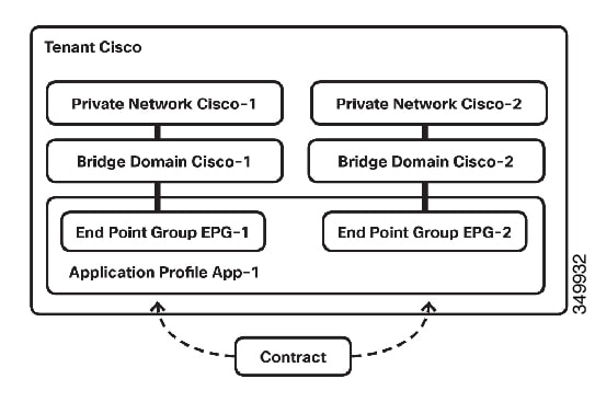
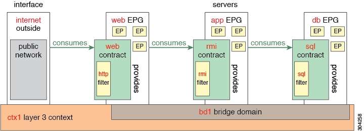
The EPG is the most
important fundamental object in the policy model. It represents a collection of
endpoints that are treated in the same fashion from a policy perspective.
Rather than configure and manage those endpoints individually, they are placed
within an EPG and are managed as a collection or group.
The EPG object is
where labels are defined that govern what policies are applied and which other
EPGs can communicate with this EPG. It also contains a reference to the bridge
domain that the endpoints within the EPG are associated with as well as which
virtual machine manager (VMM) domain they are associated with. VMM allows
virtual machine mobility between two VM servers instantaneously with no
application downtime.
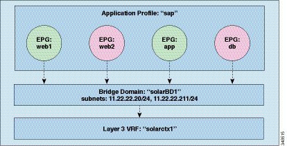
The first EPG in the
example is named “web1.” The
fvRsBd element within the EPG defines which bridge
domain that it is associated with. The bridge domain is identified by the value
of the
tnFxBDName attribute. This EPG is associated with the
“solarBD1” bridge domain named in the “Bridge Domain” section above. The
binding to the bridge domain is used by the system to understand what the
default gateway address should be for the endpoints in this EPG. It does not
imply that the endpoints are all in the same subnet or that they can only
communicate through bridging. Whether an endpoint’s packets are bridged or
routed is determined by whether the source endpoint sends the packet to its
default gateway or the final destination desired. If it sends the packet to the
default gateway, the packet is routed.
The VMM domain used
by this EPG is identified by the
fvRsDomAtt tag. This element references the VMM domain
object defined elsewhere. The VMM domain object is identified by its
tDn
name attribute. This example shows only one VMM domain called
“uni/vmmp-VMware/dom-mininet.”
The next element in
the “web1” EPG defines which contract this EPG provides and is identified by
the
fvRsProv tag. If “web1” were to provide multiple
contracts, there would be multiple
fvRsProv elements. Similarly, if it were to consume one
or more contracts, there would be
fvRsCons elements as well.
The
fvRsProv element has a required attribute that is the
name of the contract that is being provided. “web1” is providing the contract
“webCtrct” that was defined earlier that was called
tDn=“uni/tn-coke/brc-webCtrct”.
The next attribute
is the
matchT attribute, which has the same semantics for
matching provider or consumer labels as it did in the contract for subject
labels (it can take on the values of
All,
AtLeastOne, or
None). This criteria applies to the provider labels as
they are compared to the corresponding consumer labels. A match of the labels
implies that the consumer and provider can communicate if the contract between
them allows it. In other words, the contract has to allow communication and the
consumer and provider labels have to match using the match criteria specified
at the provider.
The consumer has no
corresponding match criteria. The match type used is always determined by the
provider.
Inside the provider
element,
fvRsProv, an administrator needs to specify the labels
that are to be used. There are two kinds of labels, provider labels and
provider subject labels. The provider labels,
vzProvLbl, are used to match consumer labels in other
EPGs that use the
matchT criteria described earlier. The provider subject
labels,
vzProvSubjLbl, are used to match the subject labels
that are specified in the contract. The only attribute of the label is its name
attribute.
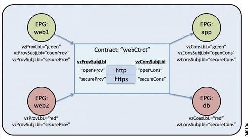
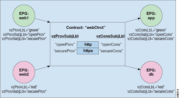
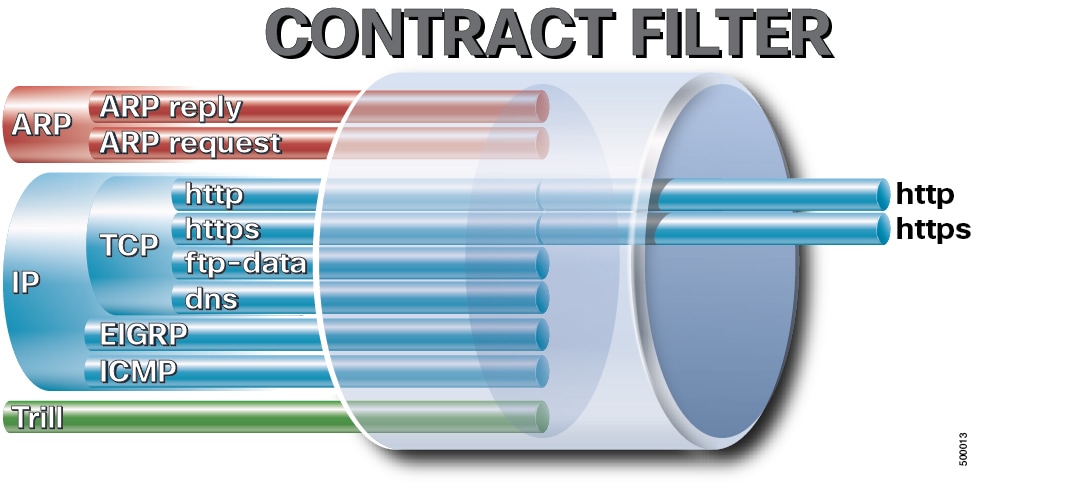
In the “web1” EPG,
two provider subject labels,
openProv and
secureProv, are specified to match with the “http” and
“https” subjects of the “webCtrct” contract. One provider label, “green” is
specified with a match criteria of
All
that will match with the same label in the “App” EPG.
The next EPG in the
example, “web2,” is very similar to “web1” except that there is only one
vzProvSubjLbl and the labels themselves are different.
The third EPG is one
called “app” and it is defined as follows:
            <fvAEPg name="app">
                <fvRsBd tnFvBDName="solarBD1" />
                <fvRsDomAtt tDn="uni/vmmp-VMware/dom-mininet" />
                <fvRsCons tnVzBrCPName="webCtrct">
		                  <vzConsSubjLbl name="openCons"/>
		                  <vzConsSubjLbl name="secureCons"/>
                    <vzConsLbl name="green"/>
                 </fvRsCons>
            </fvAEPg>
The first part is
nearly the same as the “web1” EPG. The major difference is that this EPG is a
consumer of the “webCtrct” and has the corresponding consumer labels and
consumer subject labels. The syntax is nearly the same except that “Prov” is
replaced by “Cons” in the tags. There is no match attribute in the
FvRsCons element because the match type for matching
the provider with consumer labels is specified in the provider.
In the last EPG,
“db” is very similar to the “app” EPG in that it is purely a consumer.
While in this
example, the EPGs were either consumers or producers of a single contract, it
is typical for an EPG to be at once a producer of multiple contracts and a
consumer of multiple contracts.


 Feedback