Deploy the Firewall Threat Defense Virtual on Megaport

This guide provides information on integrating the Cisco Secure Threat Defense Virtual with Megaport by deploying the Threat Defense Virtual as a Megaport Virtual Edge (MVE).

Overview

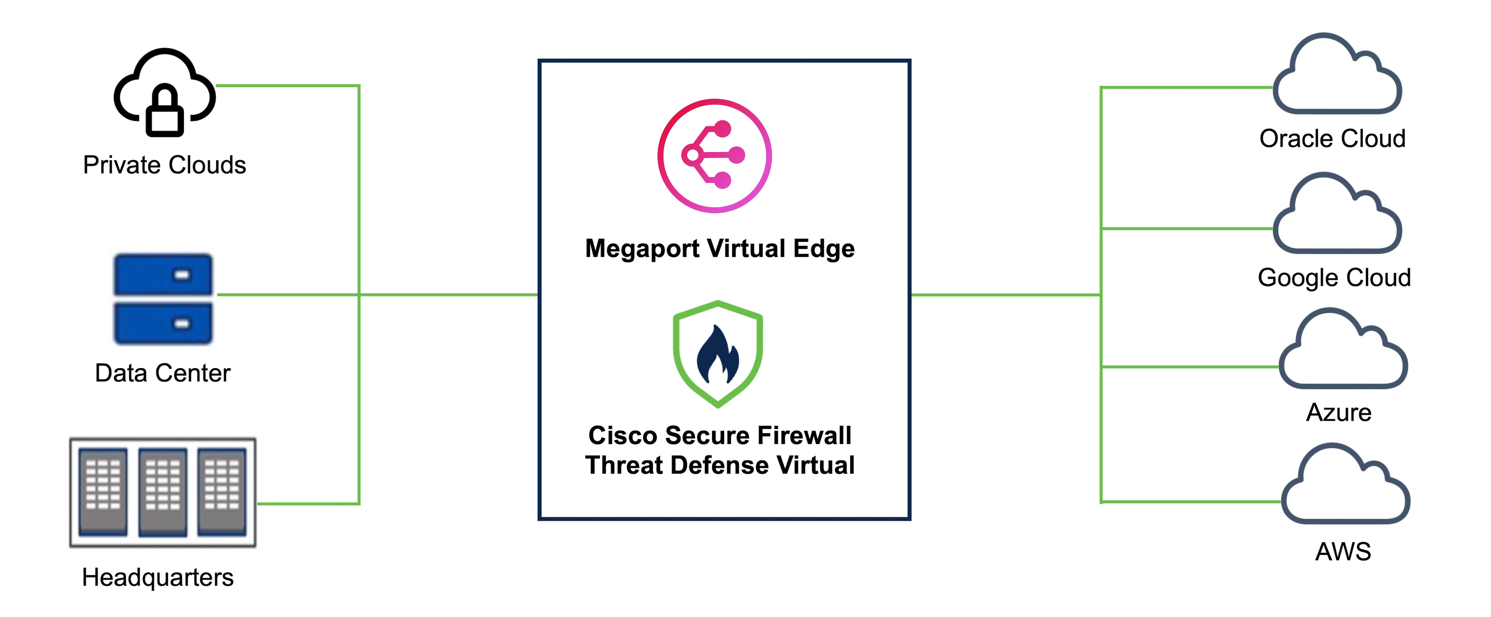
Business critical data can originate from diverse sources ranging from multiple public clouds, private clouds, and internal servers to a remote employee's device. Securing each data entity individually is time consuming and challenging due to lack of compliance between all the data points. With the increase in such use cases, you must be able to deploy the firewall quickly and securely at your network edge in a way that provides scalability and flexibility.

Megaport Virtual Edge (MVE) is an on-demand Network Function Virtualization (NFV) service on Megaport’s Software Defined Network (SDN), with a global reach of more than 280 cloud on-ramps and more than 800 data centers. The MVE enables you to secure branch-to-cloud, cloud-to-cloud, and branch-to-branch connectivity over private networks, Layer-2 networks with dedicated bandwidth, and low latency. From the Megaport portal, you can deploy SD-WAN gateways, virtual routers, transit gateways, and virtual firewalls at the network edge.

From Secure Firewall version 7.2.8, you can deploy the Threat Defense Virtual as an MVE that enables you to create a security service chain in your hybrid and multi-cloud workflows; and deploy a single point solution for personal devices, data centers, and the closest availability zones of your cloud platforms such as AWS, Azure, and GCP. This integration reduces data transit over potentially unsecure networks and allows you to seamlessly implement your security solution without worrying about problems with robustness and scalability.

Use the Megaport portal to deploy the Threat Defense Virtual and connect all your data centers to multi-cloud applications in a single place. All the data packets are routed using Megaport’s private global network. After deployment, the Threat Defense Virtual can be managed by either the on-box Firewall Device Manager, the Cloud-Delivered Firewall Management Center, or the On-Premises Firewall Management Center.

Figure 1. High-level Sample Topology

Guidelines and Limitations to Deploy the Threat Defense Virtual as a Megaport Virtual Edge

  • The following MVE compute sizes are supported:

    • 4/16 - 4 CPUs, 16 GB RAM

    • 8/32 - 8 CPUs, 32 GB RAM

    • 12/48 - 12 CPUs, 48 GB RAM

  • A minimum of 4 and a maximum of 5 interfaces are supported.

  • High Availability (HA) is supported. For more information, see Configure High Availability (Failover).

  • For initial troubleshooting if you run into any issues, see the initial boot log by using the expert command to enter the Threat Defense virtual expert mode, and then use the cat firstboot.S96ovf-data.pl command.

  • Use the CLI to reboot the Threat Defense virtual instance. There is no option to reboot the Threat Defense virtual instance from the Megaport Portal.

  • An interface cannot be deleted after deployment. You can only disable it.

  • DHCP IPv6 addressing is not supported.

  • Clustering is not supported.

Prerequisites to Deploy the Threat Defense Virtual as a Megaport Virtual Edge

  • You should have an account on the Megaport Portal with appropriate permissions to create a MVE. See Creating an Account for more information.

  • (Optional) If required, you can opt for a smart license to register your firewall. Click Cisco Software Licensing and Smart Accounts for more information.


    Note


    If you do not have a license, you must enable the Evaluation mode on your Secure Firewall Management Center or Device Manager.


Deploy the Threat Defense Virtual as a Megaport Virtual Edge

Perform the procedure given below to deploy Cisco Secure Firewall Threat Defense Virtual as a Megaport Virtual Edge.

Procedure


Step 1

Open the Megaport Portal and click Services.

Step 2

Click Create MVE.

Step 3

Choose the required MVE Location. We recommend choosing a location that is geographically closer to your end target.

Ensure that you note the diversity zone colour of your location. We recommend deploying any other required connectors, explained later in the procedure, in the same diversity zone.

Step 4

Click Next.

Step 5

Under MVE Configuration, from the list of vendors, choose the required version of the Cisco Secure Firewall Threat Defense Virtual.

Note


Ensure that you choose a version that is compatible with the Firewall Management Center that you will use. The version of your Firewall Management Center should be equal to or higher than the Cisco Threat Defense Virtual version. To verify the version of your FMC, see Verify Firepower Software Versions.

Step 6

Enter the Cisco Secure Firewall Threat Defense Virtual Service Details.

  1. Enter a name for your Firewall in the MVE Name field.

  2. Choose the Size, represented in CPU/RAM format,from the drop-down list depending on the needed throughput. See the Cisco Secure Firewall Threat Defense Virtual Data Sheet for more information.

  3. (Optional) Enter an identifier for billing purposes in the Service level reference field.

  4. Enter a password for your firewall in the Admin Password field.

  5. If you want to use the on-box Device Manager, check the Manage Locally checkbox.

  6. If you want to use the Management Center (virtual or on-prem), enter the IP address or the domain name in the FMC IP Address field.

  7. Enter an FMC Registration Key for device registration. This key is a shared secret alphanumeric string (2-36 characters). Only alphanumeric characters, hyphen (-), underscore (_), and period (.) are allowed.

  8. (Optional) Enter a NAT ID. This is an alphanumeric string that is used by the Management Center and the device during the registration process if one side does not specify an IP address. You have to specify the same NAT ID on the Management Center.

  9. Add and name all the required virtual interfaces. By default, the Threat Defense Virtual has one management, one diagnostic, and two data interfaces set up. Click +Add to add up to 5 vNICs to an MVE in Megaport. This means that you can add one more data interface if needed.

    Note


    If you want to increase or decrease the number of vNICs on this MVE after deployment, you have to delete and recreate the entire MVE. You cannot add or delete vNICs on an MVE that is already deployed.

  10. Choose the Minimum Term required based on your security needs and budget.

Step 7

Click Next.

Step 8

Verify all the details in the Summary window. Ensure that the vNICs are displayed correctly. You cannot change the vNICs after deployment.

Step 9

Click Add MVE.


What to do next

Create Megaport Internet Connection

Create Megaport Internet Connection

After the MVE is added, you will see a pop-up window suggesting creation of a Megaport Internet connection. We recommend that you create the Megaport Internet connection for your MVE to connect the deployed Threat Defense Virtual to your Management Center or use the on-box FDM.

Procedure


Step 1

Click Create Megaport Internet.

You can also create Megaport Internet later by using the Connections option under Threat Defense Virtual and selecting Megaport Internet.

Step 2

Choose the diversity zone and the target Port. We recommend selecting the same region and diversity zone color as you did while creating the MVE.

Step 3

Enter the required Connection details.

  1. Enter a Connection Name for this connection.

  2. Specify the Rate Limit that you want to put on this connection. Choosing a higher speed will incur higher cost.

  3. The VXC State defines the initial state of the connection. By default, it is set to Enabled. Leave it unchanged.

  4. A-End vNIC: This is the interface at which one end of the Megaport Internet will terminate. Choose the management interface (vNIC-0) from the drop-down list.

  5. By default, Preferred A-End VLAN is set to Untag. You can leave it as is or you can use a unique custom VLAN ID.

  6. Choose the Minimum Term required based on your security needs and budget.

Step 4

Click Next.

Step 5

Verify the details in the connection summary, and click Add VXC.

Step 6

(Optional) Repeat the steps 1 through 5 to set up internet access for the outside interface.

Step 7

On the left pane, click Order, and then click Order Now.

Note


Cisco Threat Defense Virtual can take 10-20 minutes to initialize and boot up.


Connect the Threat Defense Virtual to the Management Center or Device Manager

After the Threat Defense Virtual is deployed, use the Public IP address of the Megaport Internet connector to register to your Secure Firewall Management Center or to access the on-box Secure Firewall Device Manager.

Perform the steps given below to find out the Public IP address of your connector.

Procedure


Step 1

On the Megaport Portal, click the Services tab.

Step 2

Search for the name of your Threat Defense Virtual instance from the filter bar.

Step 3

Click the gear icon next to the Megaport Internet connector under your Threat Defense Virtual instance.

Step 4

Click Details in the top menu.

Step 5

In the Connection Details page, you will see the Public IPv4 and IPv6 address that you can use to connect the Threat Defense Virtual to the Management Center or Device Manager.


Connect the Threat Defense Virtual to the Public Cloud Platforms

To secure your multicloud or hybrid cloud deployment, set up a connection between the newly deployed Threat Defense Virtual and your public cloud platforms. You can do so by creating a Virtual Cross Connect (VXC).

Perform the steps given below to create a VXC.

Procedure


Step 1

On the Megaport portal, click the Services tab

Step 2

Click + Connection for the Threat Defense virtual instance that has to be connected to the public cloud.

Step 3

Choose Cloud as the Destination Type to connect your cloud architecture to the Threat Defense Virtual using Megaport’s secured connection.

Step 4

Click Next.

Step 5

Choose the public cloud Provider that has to be connected to the Threat Defense Virtual and fill in the required details.

Step 6

Click Next and enter the required Connection Details.


Configure High Availability (Failover)

Cisco Secure Firewall Threat Defense Virtual supports Active/Standby failover, in which one unit is the active unit and passes traffic. The standby unit does not actively pass traffic but synchronizes configuration and other state information with the active unit. When a failover occurs, the active unit fails over to the standby unit, which then becomes active.

To configure High Availability on Megaport, deploy two identical Threat Defense Virtual instances as MVEs. To understand other hardware and software requirements for the configuration of HA in the Cisco Threat Defense Virtual, see High Availability.

After configuring HA, create a Private VXC between both the Threat Defense Virtual instances. This connection is required for the failover link to work. Perform the steps given below to create a private VXC.

Procedure


Step 1

Under the primary Threat Defense Virtual, click the +Connection icon and then click the Private VXC destination type.

Step 2

Choose the secondary Threat Defense Virtual from the Destination Port list.

Step 3

Enter the required Connection details.

  1. Enter a Connection Name for your connection.

  2. Specify the Rate Limit that you want to put on this connection. Choosing a higher speed will incur higher cost.

  3. The VXC State defines the initial state of the connection. By default, it is set to enabled. Leave it unchanged.

  4. For the A-End vNIC and B-End vNIC, choose the required interface from both the Threat Defense Virtual instances. This connection between these two interfaces acts as a failover link.

  5. (Optional) Enter a unique VLAN ID for your topology.

  6. Click Next.

  7. Click Add VXC.

  8. Finalize the order in the left pane.

For more information on configuring HA on the Threat Defense Virtual with the Management Center or Device Manager, see the following guides: