Configure Cisco Products in Cisco Security Cloud App

This chapter explains how to add and configure inputs for various Cisco products within Security Cloud App. Configuring inputs correctly is important because it defines the data sources that Security Cloud App uses for monitoring. Proper configuration ensures comprehensive security coverage and displays all data accurately for future tracking and monitoring.


Important


In a distributed Splunk architecture, it is critical that modular inputs are configured and executed only on the Heavy Forwarder (HF), not on Search Heads or Indexers.


Set Up an Application

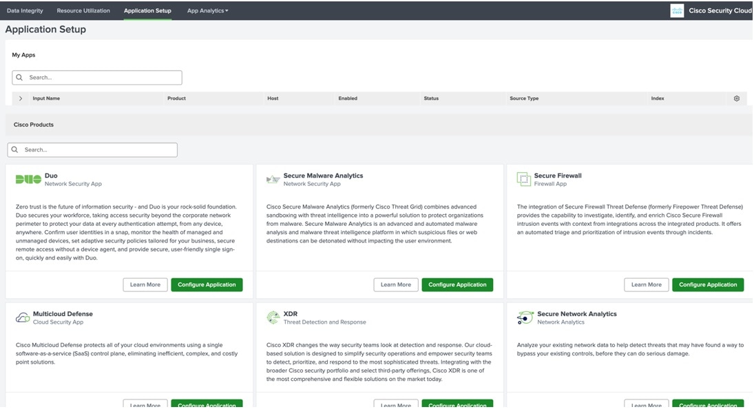
Application Setup is the first user interface for Security Cloud App. The Application Setup page consists of two sections:

Figure 1. My Apps
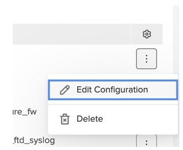
  • The My Apps section on the Application Setup page displays all user input configurations.

  • Click a product hyperlink to go to the product dashboard.

  • To edit inputs, click Edit Configuration under the action menu.

  • To delete inputs, click Delete under the action menu.

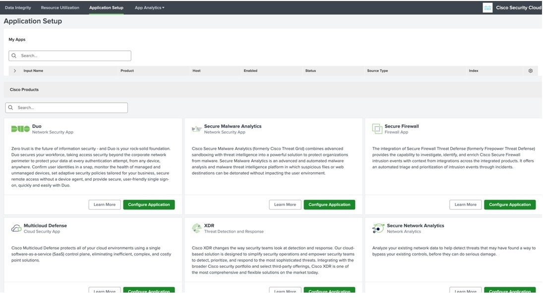
Figure 2. Cisco Products

The Cisco Products page displays all available Cisco products that are integrated with Security Cloud App.

You can configure inputs for each Cisco product in this section.

Configure an Application

Some configuration fields are common across all Cisco products and they are described in this section.

Configuration fields that are specific to a product are described in the later sections.
Table 1. Common fields

Field

Description

Input Name

(Mandatory) A unique name for inputs of the application.

Interval

(Mandatory) Time interval in seconds between API queries.

Index

(Mandatory) Destination index for application logs. It can be changed if required.

Auto-complete is provided for this field.

Source Type

(Mandatory) For most apps it is a default value and is disabled.

You can change its value in Advance Settings.

Procedure


Step 1

In the Application Setup > Cisco Products page, navigate to the required Cisco application.

Step 2

Click Configure Application.

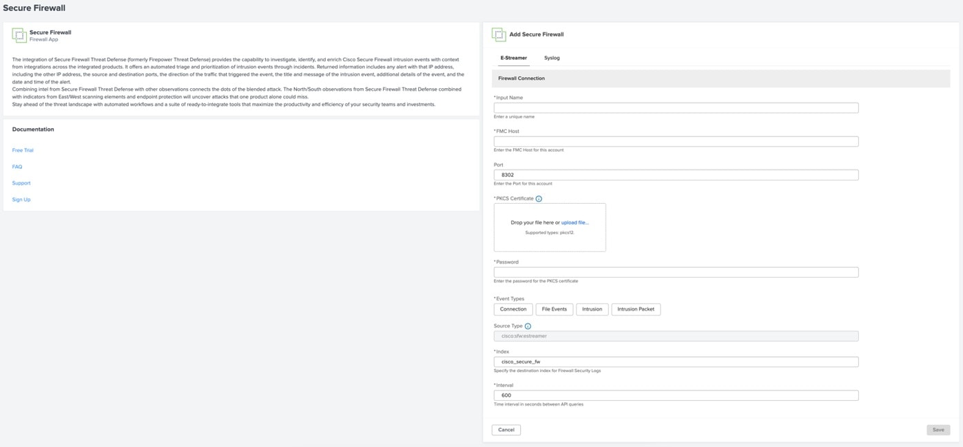
The configuration page consists of three sections: Brief app description, Documentation with links to useful resources, and Configuration form.

Step 3

Fill in the configuration form. Note the following:

  • Required fields are marked with asterisk *.

  • There are also optional fields.

  • Follow the instructions and tips described in the specific app section of the page.

Step 4

Click Save.

If there is an error or empty fields, the Save button is disabled. Correct the error and save the form.


Cisco Duo

Figure 3. Duo Configuration page

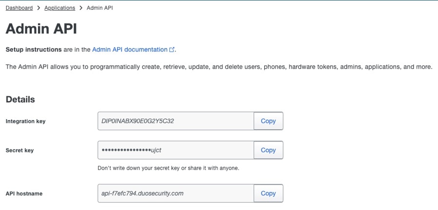
In addition of the mandatory fields described in the Configure an Application section, the following credentials are required for authorization with Duo API:

  • ikey (Integration key)

  • skey (Secret key)

Authorization is handled by the Duo SDK for Python.

Table 2. Duo configuration fields

Field

Description

API Hostname

(Mandatory ) All API methods use the API hostname. https://api-XXXXXXXX.duosecurity.com.

Obtain this value from the Duo Admin Panel and use it exactly as shown there.

Duo Security Logs

Optional.

Proxy Settings

Optional.

Logging Level

(Optional) Logging level for messages written to input logs in $SPLUNK_HOME/var/log/splunk/duo_splunkapp/

Procedure


Step 1

In the Duo configuration page, enter the Input Name.

Step 2

Enter the Admin API credentials in the Integration key, Secret key, and the API hostname fields. If you do not have these credentials, register a new account.

  • Navigate to Applications > Protect an Application > Admin API to create new Admin API.

Step 3

Define the following, if required:

  • Duo Security Logs

  • Proxy Settings

  • Logging Level

Step 4

Click Save.


Cisco Secure Malware Analytics

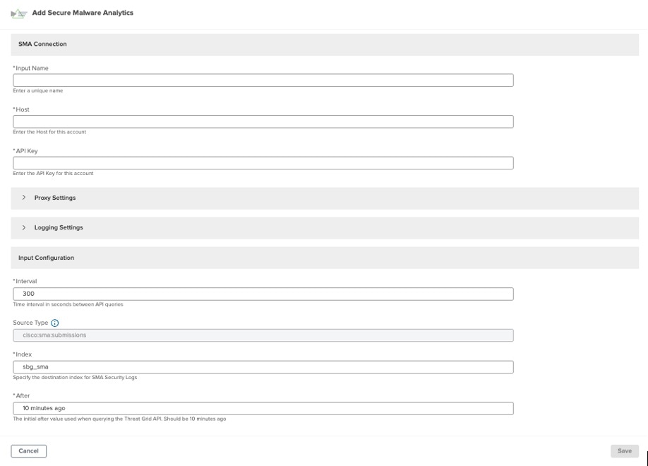
Figure 4. Secure Malware Analytics Configuration page


Note


You need an API key (api_key) for authorization with Secure Malware Analytics (SMA) API

Pass the API key as the Bearer type in the Authorization token of the request.

Secure Malware Analytics configuration data

  • Host: (Mandatory) Specifies the name of the SMA account.

  • Proxy Settings: (Optional) Consists of Proxy Type, Proxy URL, Port, Username, and Password.

  • Logging Settings: (Optional) Define the settings for logging information.


Procedure


Step 1

In the Secure Malware Analytics configuration page, enter a name in the Input Name.

Step 2

Enter the Host and the API Key fields.

Step 3

Define the following, if required:

  • Proxy Settings

  • Logging Settings

Step 4

Click Save.


Cisco Secure Firewall Management Center

Figure 5. Secure Firewall Management Center Configuration page

You can import data into the Secure Firewall application using any one of the two streamlined processes: eStreamer and Syslog.

The Secure Firewall configuration page provides two tabs, each corresponding to a different data import method. You can switch between these tabs to configure the respective data inputs.

Firewall e-Streamer

eStreamer SDK is used for communication with Secure Firewall Management Center.

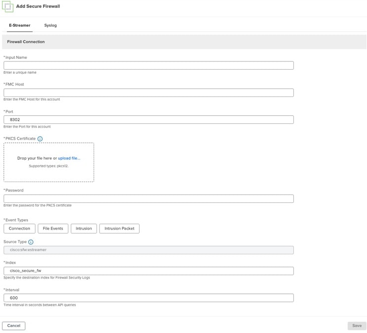
Figure 6. Secure Firewall E-Streamer tab
Table 3. Secure Firewall configuration data

Field

Description

FMC Host

(Mandatory) Specifies the name of the management center host.

Port

(Mandatory) Specifies the port for the account.

PKCS Certificate

(Mandatory) Certificate must be created on the Firewall Management Console - eStreamer Certificate Creation. The system supports only pkcs12 file type.

Note


For Splunk instances with FIPS mode enabled, the PBE algorithms, that protect thepkcs12 file must be FIPS compliant.

To reassign certificates with the PBE algorithm, execute the following commands:

OpenSSL> pkcs12 -in ftdv_C_.p12 -out ftdv_C_.pem
See Troubleshoot PKCS#12 File Installation Failure with Non-FIPS Compliant PBE Algorithms for more information.

Password

(Mandatory) Password for the PKCS Certificate.

Event Types

(Mandatory) Choose the type of events to ingest (All, Connection, Intrusion, File, Intrusion Packet).

Procedure


Step 1

In the E-Streamer tab of the Add Secure Firewall page, in the Input Name field, enter a name.

Step 2

In the PKCS Certificate space, upload a .pkcs12 file to set up the PKCS certificate.

Step 3

In the Password field, enter the password.

Step 4

Choose an event under Event Types.

Step 5

Define the following, If required:

  • Duo Security Logs

  • Logging Level

Note


If you switch between the E-Streamer and Syslog tabs, only the active configuration tab is saved. Therefore, you can only set one data import method at a time.

Step 6

Click Save.


Firewall Syslog and ASA

In addition to the mandatory fields that are described in the Configure an Application section, the following are the configurations that are required on the management center side.

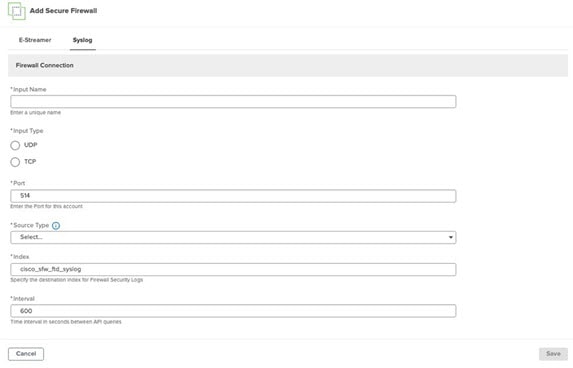
Table 4. Configuration fields to add a Syslog

Field

Description

TCP/UDP

(Mandatory)Specifies the type of input data.

Port

(Mandatory)Specifies a unique port for the account.

Procedure


Step 1

In the Syslog tab of the Add Secure Firewall page, set up the connection on the management center side, in the Input Name field, enter a name.

Figure 7. Configure Syslog

Step 2

Choose TCP or UDP for the InputType.

Step 3

In the Port field, enter the port number.

Step 4

Select a type from the SourceType drop-down list.

Step 5

Choose event types for the selected source type.

Note


If you switch between the E-Streamer and Syslog tabs, only the active configuration tab is saved. Therefore, you can only set one data import method at a time.

Step 6

Click Save.


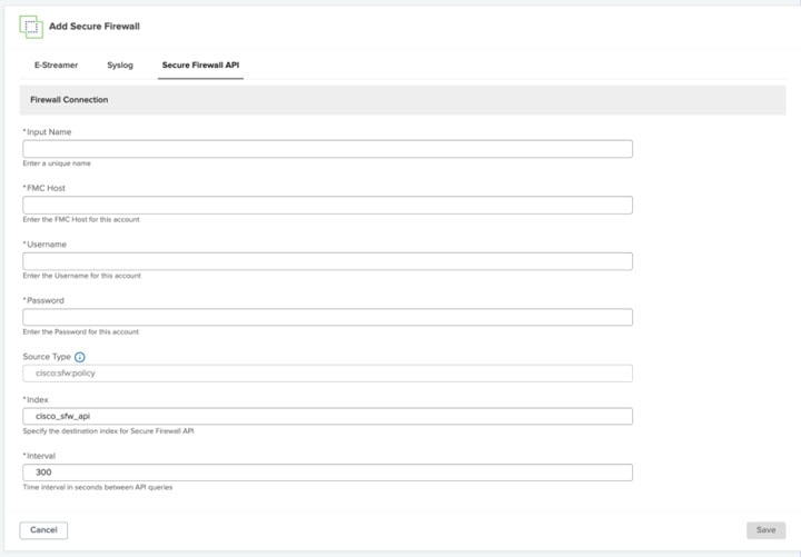
Firewall API

Along with the required fields described in the Configure an Application, the Secure Firewall Threat Defense REST API is used.

Complete configuration procedure with the following steps:

Procedure


Step 1

In the Secure Firewall API tab of the Add Secure Firewall page, enter a unique name in the Input Name field.

Figure 8. Secure Firewall API

Step 2

In the FMC Host field enter the FMC host for the account.

Step 3

In the Username and Password fields, enter the username and password for the account.

Step 4

Click Save.

If you switch between the tabs on the Add Secure Firewall page, only the active configuration tab is saved. Therefore, you can only set one data import method at a time.

Step 5

Click Save.


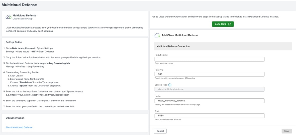
Cisco Multicloud Defense

Figure 9. Secure Malware Analytics Configuration page

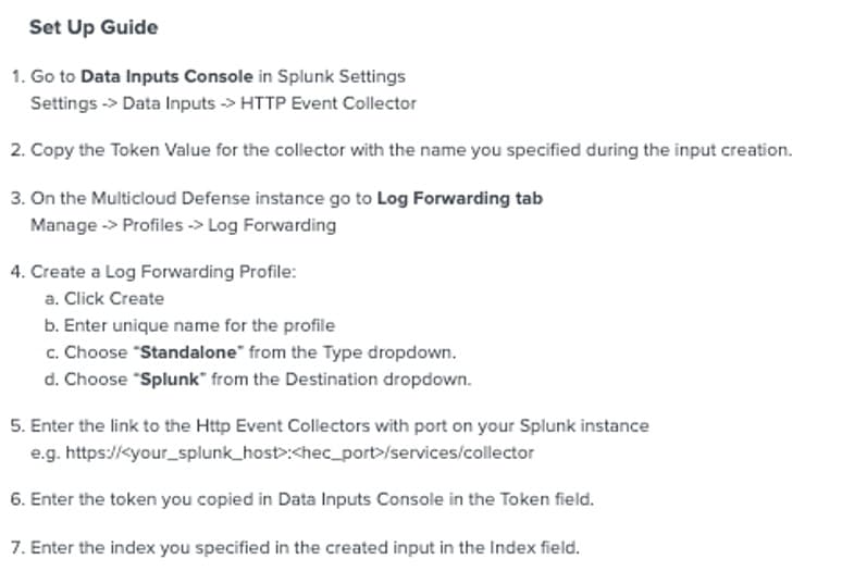
Multicloud Defense (MCD) leverages the HTTP Event Collector functionality of Splunk instead of communicating through an API.

Create an instance in Cisco Defense Orchestrator (CDO), by following the steps that are defined in the Set Up Guide section of the Multicloud Defense configuration page.

Only the mandatory fields defined in the Configure an Application section are required for authorization with Multicloud Defense.

Procedure


Step 1

Install a Multicloud Defense instance in CDO by following the Set Up Guide on the configuration page.

Step 2

Enter a name in the Input Name field.

Step 3

Click Save.


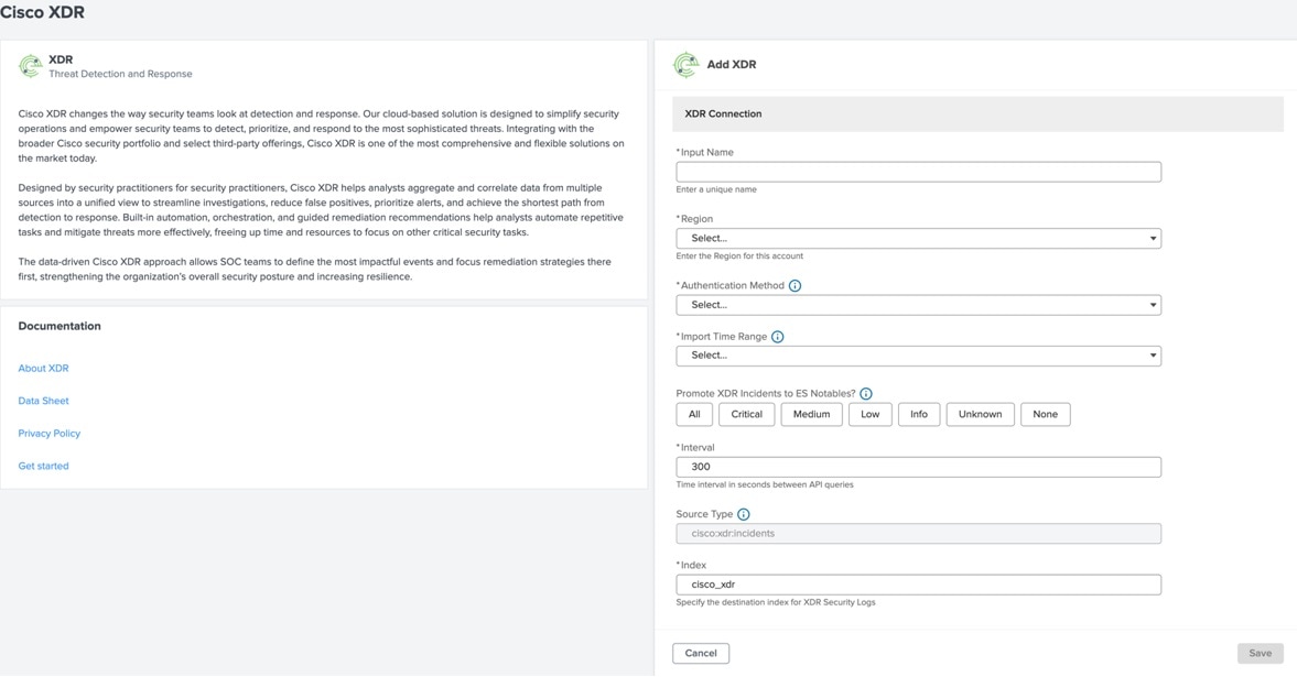
Cisco XDR

Figure 10. XDR Configuration page

The following credentials are required for authorization with Private Intel API:

  • client_id

  • client_secret

Every input run results in a call to GET /iroh/oauth2/token endpoint to obtain a token that is valid for 600 seconds.

Table 5. Cisco XDR configuration data

Field

Description

Region

(Mandatory) Select a region before selecting an Authentication Method.

Authentication Method

(Mandatory) Two authentication methods are available: Using Client ID and OAuth.

Import Time Range

(Mandatory) Three import options are available: Import All Incident data, Import from created date-time, and Import from defined date-time.

Promote XDR Incidents to ES Notables?

(Optional) Splunk Enterprise Security (ES) promotes Notables.

If you have not enabled Enterprise Security, you can still choose to promote to notables, but events do not appear in that index or notable macros.

After you enable Enterprise Security, events are present in the index.

You can choose the type of incidents to ingest (All, Critical, Medium, Low, Info, Unknown, None).

Procedure


Step 1

In the Cisco XDR configuration page, enter a name in the Input Name field.

Step 2

Select a method from the Authentication Method drop-down list.

  • Client ID:

    1. Click the Go to XDR button to create a client for your account in XDR.

    2. Copy and paste the Client ID

    3. Set a password (Client_secret)

  • OAuth:

    1. Follow the generated link and authenticate. You need to have an XDR account.

    2. If the first link with the code didn’t work, in the second link, copy the User code and paste it manually.

Step 3

Define an import time in the Import Time Range field.

Step 4

If required, select a value in the Promote XDR Incidents to ES Notables? field.

Step 5

Click Save.


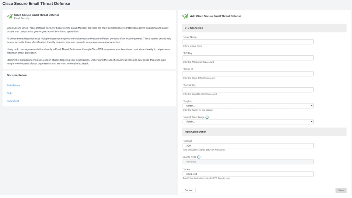
Cisco Secure Email Threat Defense

Figure 11. Secure Email Threat Defense Configuration page

The following credentials required for authorization of Secure Email Threat Defense APIs:

  • api_key

  • client_id

  • client_secret

Table 6. Secure Email Threat Defense configuration data

Field

Description

Region

(Mandatory) You can edit this field to change the region.

Import Time Range

(Mandatory) Three options are available: Import All message data, Import from created date-time, Import from defined date-time.

Procedure


Step 1

In the Secure Email Threat Defense configuration page, enter a name in the Input Name field.

Step 2

Enter the API Key, Client ID, Client Secret Key.

Step 3

Select a region from the Region drop-down list.

Step 4

Set an import time under Import Time Range.

Step 5

Click Save.


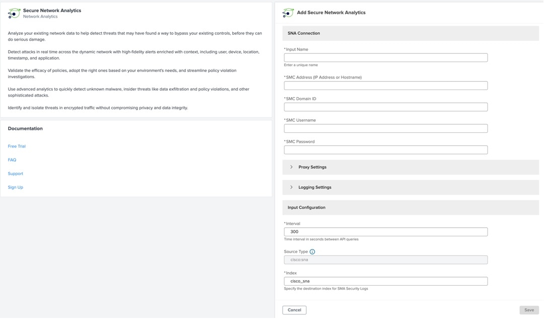
Cisco Secure Network Analytics

Secure Network Analytics (SNA), formerly known as Stealthwatch, analyzes the existing network data to help identify threats that may have found a way to bypass the existing controls.

Figure 12. Secure Network Analytics Configuration page

Credentials required for authorization:

  • smc_host: (IP address or hostname of the Stealthwatch Management Console)

  • tenant_id (Stealthwatch Management Console domain ID for this account)

  • username (Stealthwatch Management Console username)

  • password (Stealthwatch Management Console password for this account)

Table 7. Secure Network Analytics configuration data

Field

Description

Proxy type

choose a value from the drop-down list:

  • Host

  • Port

  • Username

  • Password

Interval

(Mandatory) Time interval in seconds between API queries. By default, 300 secs.

Source type

(Mandatory)

Index

(Mandatory) Specifies the destination index for SNA Security Logs. By default, state: cisco_sna .

After

(Mandatory) The initial after value used when querying the Stealthwatch API. By default, the value is 10 minutes ago.

Logging Settings

(Optional)

Promote SNA Alarms to ES Notables?

(Optional)

After ES is enabled, events are available in the index. You can choose the incident level that must be ingested (All, Critical, Major, Minor, Trivial, or Info)

Note


Splunk Enterprise Security is required to promote Notables. In case you do not have it, you can still can enable this option, but events will not appear in the index index or by notable macros.

Procedure


Step 1

In the Secure Network Analytics configuration page, enter a name in the Input Name field.

Step 2

Enter Manager Address (IP or Host), Domain ID, Username, and Password.

Step 3

If required, set the following under Proxy settings:

  • Choose a proxy from the Proxy type drop-down list.

  • Enter the host, port, username, and password in the respective fields.

Step 4

Define the Input configurations:

  • Set a time under Interval. By default, the interval is set to 300 seconds (5 minutes).

  • You can change the Source type under Advanced Settings, if required. Default value is cisco:sna.

  • Enter the destination index for the Security logs in the Index field.

Step 5

Click Save.


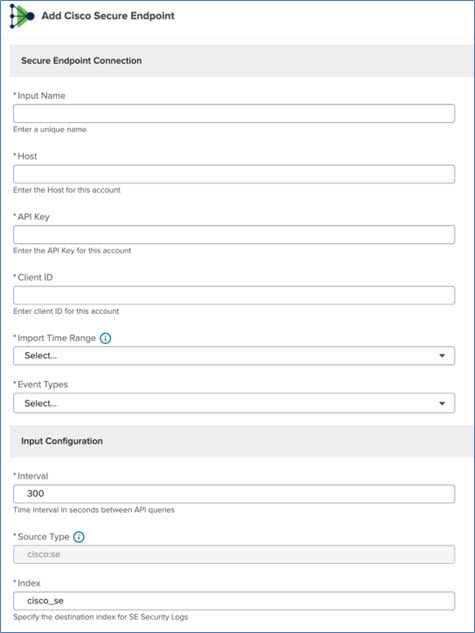
Cisco Secure Endpoint

Cisco Secure Endpoint (SE) is a single-agent solution that provides comprehensive protection, detection, response, and user access coverage to defend against threats to your endpoints.

Configure the following in the Add Cisco Secure Endpoint page:

Before you begin

Credentials are required for authorization:
  • api_host: host for SE

  • api_key: API key (password) for the account SE

  • client_id: client id (username) for the account SE

Procedure


Step 1

Enter the values for all the fields as described in the following table:

Field

Description

Input Name

(Mandatory)Unique name for the input

Import Time Range (Mandatory)Choose a date to import data
Event type (Mandatory) You can select more than one event types.
Interval

(Mandatory)Time interval between API queries.

By default, the interval is 300 secs.

Range is 1 to 900.

Source Type

By default, the source type is cisco:se.

This field is disabled by default.

To enable and change the source type, go to Advance Settings.

Index

Specifies the destination index for SE Security Logs.

By default, the value is cisco:se.

Groups This field is displayed only you enter the correct credentials (api_host, api_key, and client_id)
After you enter the input name, host id, API key, and client ID, the Groups field is enabled.

Step 2

In the Groups drop-down list, select the required groups. You can select more than one group.

Step 3

From the Import Time Range drop-down list, choose a timeline to import the data.

Step 4

From the Event Types drop-down list, choose one or more events.

Step 5

In the Interval field, set the interval between API queries.

Step 6

To submit the form, click Save.


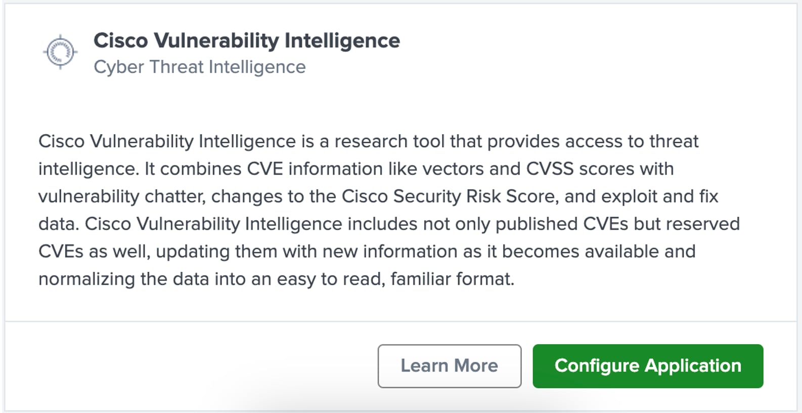
Cisco Vulnerability Intelligence

Cisco Vulnerability Intelligence (CVI) gives access to a collection of vulnerability information that includes Common Vulnerabilities and Exposures (CVE) data, through an API. You can access CVI through the Cisco Vulnerability Management platform.

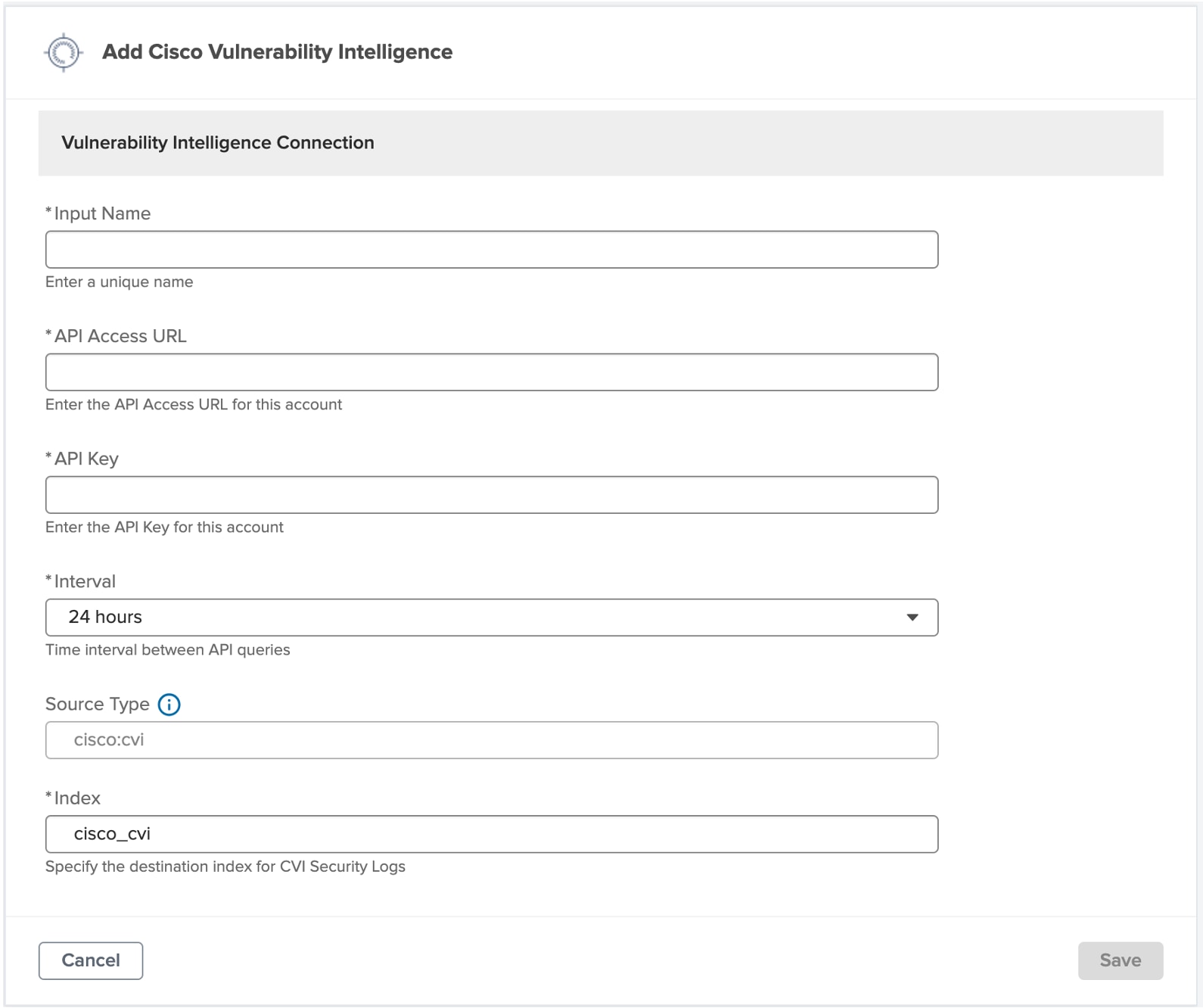
Here is a description of the mandatory configuration input fields in the Add Cisco Vulnerability Intelligence page.

Table 8. CVI configuration data

Field

Description

Input Name

A name for this connection.

API Access URL

The endpoint for your instance of CVM. This URL can be found on the Settings > API Keys > API Key Access & Generation page in CVM. Enter only the domain name and include a front slash at the end.

For example, api.kennasecurity.com/

API Key

The API Key generated from the Settings > API Keys page in CVM.

Interval

Time interval between the API queries. By default, it is 24 hours.

The fields Source Type and Index have a default value, which you can retain.

Use the following procedure to configure Cisco Vulnerability Intelligence.

Procedure


Step 1

In the Application Setup page of Security Cloud App, go to the Cisco Products section and search for Cisco Vulnerability Intelligence.

Step 2

In the Cisco Vulnerability Intelligence card, click Configure Application.

Step 3

In the Add Cisco Vulnerability Intelligence page, enter the specific connection details based on your CVM settings.

Figure 13. Configure CVI

Step 4

Click Save.

This establishes a connection to CVM. CVI data is loaded into the cisco_cvi index of your Splunk instance.


Search and Reporting Tool

The cisco_cvi index stores all vulnerability data by default. You can reference the cisco_cvi index through the Search and Reporting tool of Splunk. In the tool, you can generate reports and filter data based on the different fields.

CIM Mapping to Vulnerability Model

Along with vulnerability data in the cisco_cvi index, many fields are mapped to the CIM Vulnerability model. You can reference this mapping manually or in other tools that reference the Vulnerability model.

Splunk CIM Model

Splunk Field Name

Splunk Data Type

CVM VI + Data snapshot Field Name

Cisco Security.CVM VI Dataset

exploits

Array of structured types

exploits

Cisco Security.CVM VI Dataset

fixes

Array of structured types

fixes

Cisco Security.CVM VI Dataset

threat_actors

Array of structured types

threat_actors

Cisco Security.CVM VI Dataset

created_at

time

created_at

Cisco Security.CVM VI Dataset

daily_trend

string

daily_trend

Cisco Security.CVM VI Dataset

predicted_exploitable

boolean

predicted_exploitable

Cisco Security.CVM VI Dataset

predicted_exploitable_confidence

float

predicted_exploitable_confidence

Cisco Security.CVM VI Dataset

successful_exploitations

number

successful_exploitations

Cisco Security.CVM VI Dataset

velocity_day

number

velocity_day

Cisco Security.CVM VI Dataset

velocity_month

number

velocity_month

Cisco Security.CVM VI Dataset

velocity_week

number

velocity_week

Cisco Security.CVM VI Dataset

cve_id

string

cve_id

Cisco Security.CVM VI Dataset

cvss_score

float

cvss_score

Cisco Security.CVM VI Dataset

cvss_exploit_subscore

float

cvss_exploit_subscore

Cisco Security.CVM VI Dataset

cvss_impact_subscore

float

cvss_impact_subscore

Cisco Security.CVM VI Dataset

cvss_vector

float

cvss_vector

Cisco Security.CVM VI Dataset

cvss_temporal_score

float

cvss_temporal_score

Cisco Security.CVM VI Dataset

cvss_v3_score

float

cvss_v3_score

Cisco Security.CVM VI Dataset

cvss_v3_exploit_subscore

float

cvss_v3_exploit_subscore

Cisco Security.CVM VI Dataset

last_modified_on

_time

last_modified_on

Cisco Security.CVM VI Dataset

published_on

_time

published_on

Cisco Security.CVM VI Dataset

vulnerable_products

string

vulnerable_products

Cisco Security.CVM VI Dataset

vuln_state

string

state

Cisco Security.CVM VI Dataset

id

number

id

Cisco Security.CVM VI Dataset

cve_description

string

cve_description

Cisco Security.CVM VI Dataset

cvss_access_complexity

string

cvss_access_complexity

Cisco Security.CVM VI Dataset

cvss_access_vector

string

cvss_access_vector

Cisco Security.CVM VI Dataset

cvss_authentication

string

cvss_authentication

Cisco Security.CVM VI Dataset

description

string

description

Cisco Security.CVM VI Dataset

cisco_security_risk_score

float

risk_meter_score

Cisco Security.CVM VI Dataset

cvss_availability_impact

string

cvss_availability_impact

Cisco Security.CVM VI Dataset

cvss_confidentiality_impact

string

cvss_confidentiality_impact

Cisco Security.CVM VI Dataset

cvss_integrity_impact

string

cvss_integrity_impact

Cisco Security.CVM VI Dataset

easily_exploitable

boolean

easily_exploitable

Cisco Security.CVM VI Dataset

malware_exploitable

boolean

malware_exploitable

Cisco Security.CVM VI Dataset

active_internet_breach

boolean

active_internet_breach

Cisco Security.CVM VI Dataset

malware_count

number

malware_count

Cisco Security.CVM VI Dataset

chatter_count

boolean

chatter_count

Cisco Security.CVM VI Dataset

popular_target

boolean

popular_target

Cisco Security.CVM VI Dataset

remote_code_execution

boolean

remote_code_execution

Cisco Security.CVM VI Dataset

pre_nvd_chatter

boolean

pre_nvd_chatter

Cisco Security.CVM VI Dataset

stride_threat

Array of strings

stride_threat

Cisco Security.CVM VI Dataset

vulnerability_type

Array of strings

vulnerability_type

Cisco Security.CVM VI Dataset

exploitation_methodology

Array of strings

exploitation_methodology

Cisco Security.CVM VI Dataset

affected_source_file_module

Array of strings

affected_source_file_module

Cisco Security.CVM VI Dataset

mitre_techniques

Array of strings

mitre_techniques

Cisco AI Defense

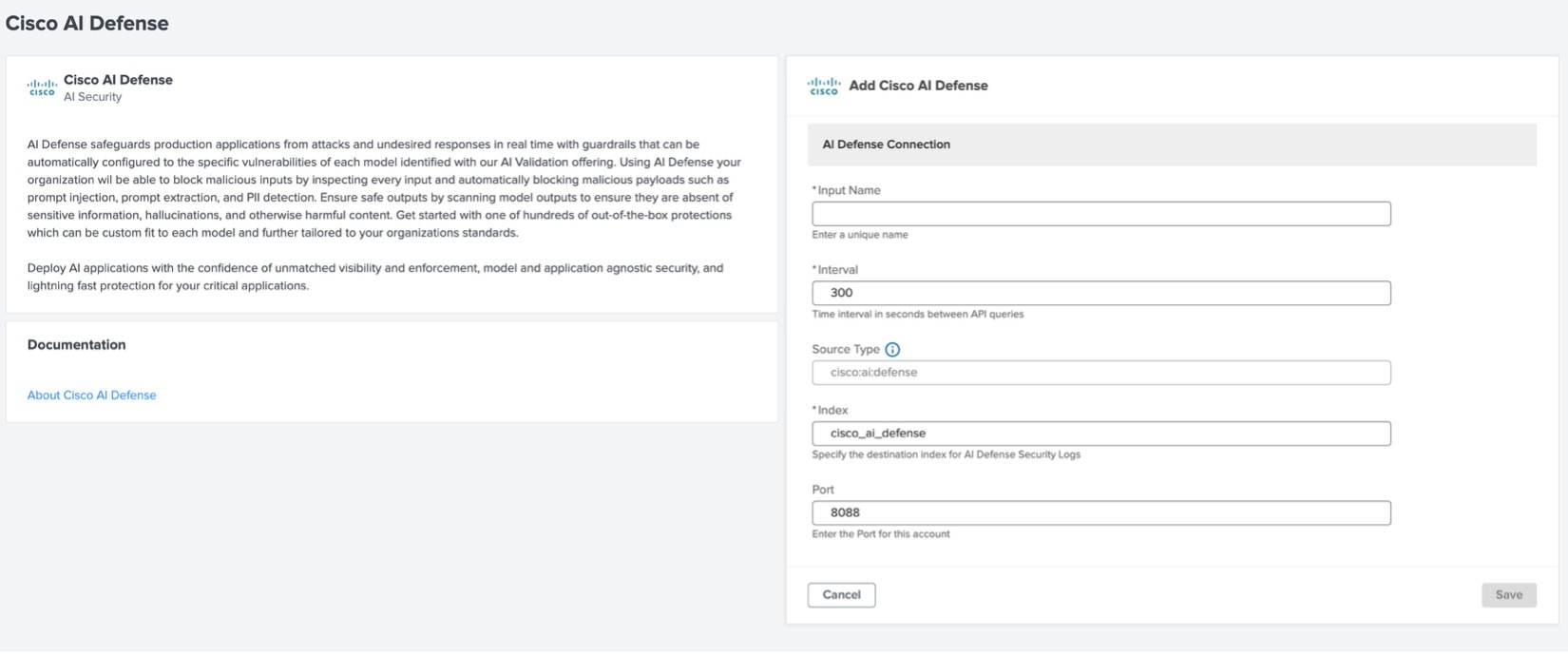
Figure 14. AI Defense Configuration on Security Cloud Control app for Splunk

Follow these steps to complete the configuration on the Splunk Cisco Security Cloud app.

Before you begin

In order to forward AI Defense events to Splunk, you must have the following in place:

Follow these steps to connect AI Defense to Splunk:

  1. From your Splunk instance, gather the following values:

    • Splunk Collector URL, including the HTTP Port Number: The URL used to access the Splunk HTTP Event Collector (HEC).

      This URL has the format, https://<splunk-server>:<hec_port>/services/collector. For example, https://mysplunkserver.example.com:8088/services/collector.

    • HTTP Event Collector Token: The Splunk Token to allow AI Defense to communicate with Splunk.

    • Index Name: The name of the Splunk index that you will use for storing AI Defense events.

  2. In AI Defense, open the Administration: Integrations tab and find the card for Splunk.

  3. Click the Connect button and enter the Splunk HEC details (Splunk Collector URL, HTTP Event Collector Token, and Index Name).

  4. Once you fill in the details, click the Connect button and the Splunk card status will show as connected.

Only the mandatory fields defined in the Configure an Application section are required for authorization with AI Defense.

Procedure


Step 1

Open the Application Setup tab and find the card for AI Defense.

Step 2

Click Configure Application.

Step 3

In the Cisco AI Defense panel, set up the AI Defense Connection. Most fields here are preconfigured and can be left as-is.

  • In the Input Name field, specify the name to be used in this connection to refer to the AI Defense data input.

  • Optionally, you can edit the Index name where the events will be stored in Splunk.

Step 4

Click Save.

The connection appears in the My Apps list of the Application Setup panel.


What to do next

Once you have added the AI Defense connection:

  • The Data Integrity tab shows the health of the connection.

  • The Resource Utilization tab shows the system resources being consumed by AI Defense.

  • The Cisco AI Defense Dashboard is available in Splunk.

Cisco Isovalent Runtime Security

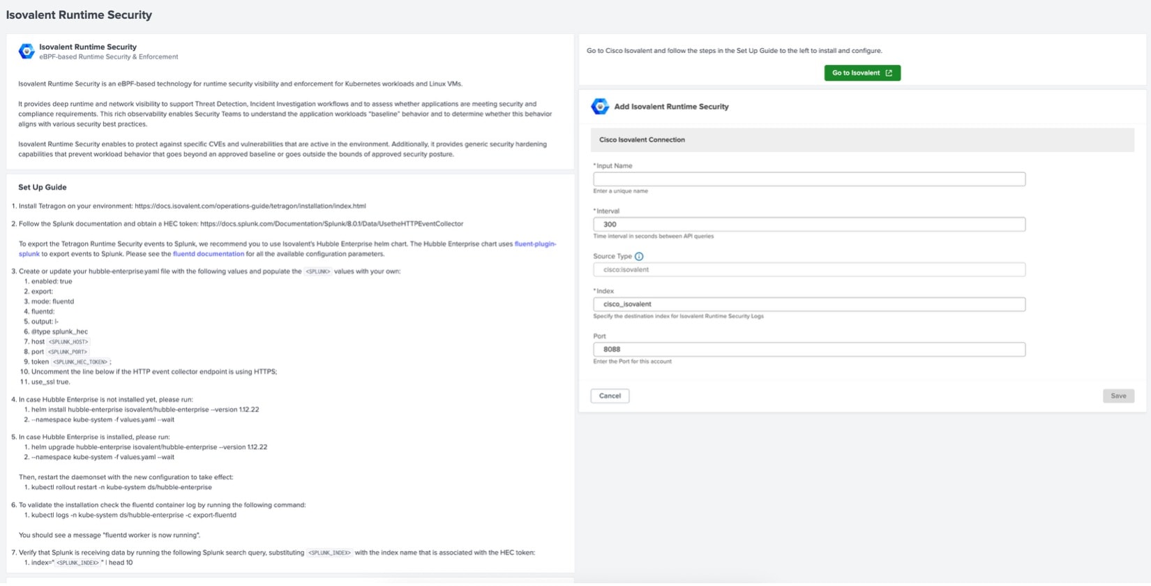
Cisco Isovalent Runtime Security configuration page looks like this:

Figure 15. Cisco Isovalent Runtime Security Configuration

Procedure


Step 1

Set up a connection on Isovalent using Setup guide in the configuration page.

Step 2

Enter a name in the Input name field.

Step 3

Click Save.


Cisco Secure Client NVM

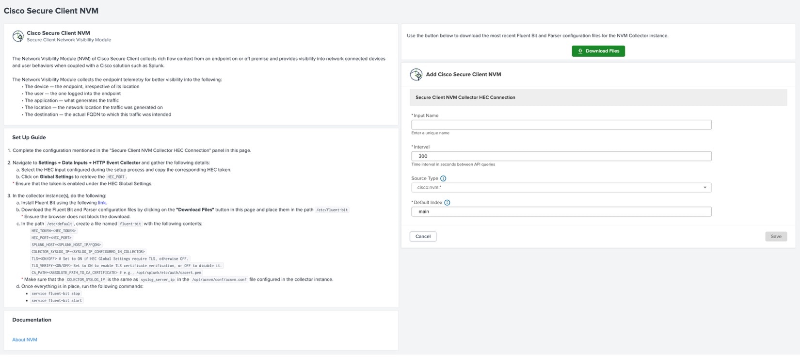
Figure 16. Cisco Secure Client NVM Configuration

The Cisco Secure Client NVM integrates with Splunk through its HTTP Event Collector (HEC), not via a direct API connection.

Before you begin

Download the Fluent Bit configuration file from the configuration page using the provided Download button.

Procedure


Step 1

Create an NVM Collector instance by following the steps that are defined in the Set Up Guide section of the Cisco Secure Client NVM configuration page.

Note


While following the setup, note the critical configuration parameters—such as the Token, Port, and Host IP—as these values are required when updating the Fluent Bit configuration for NVM.

Step 2

Enter a name in the Input Name field.

Step 3

Click Save.


Cisco Identity Intelligence (CII)

There are two primary methods to forward data from Cisco Identity Intelligence to Splunk. Choose the method that best fits your operational needs and infrastructure.

  1. Method 1: Webhooks (Recommended for Real-Time Events)

  2. Method 2: AWS S3 Bucket (Recommended for Batch Data)

Test the connectivity between Splunk and Cisco Identity Intelligence with the following steps:

Before you begin

Ensure that you meet the following prerequisites before starting the integration.

  • Administrative access to Cisco Identity Intelligence

  • Administrative access to Splunk Enterprise or Splunk Cloud

  • Cisco Security Cloud app installed from Splunkbase

  • Splunk Add-on for AWS installed from Splunkbase

  • Appropriate permissions to configure a Splunk HTTP Event Collector (HEC) or manage AWS S3 buckets and Splunk data inputs

Procedure


Step 1

In Splunk

Verify test application in Splunk

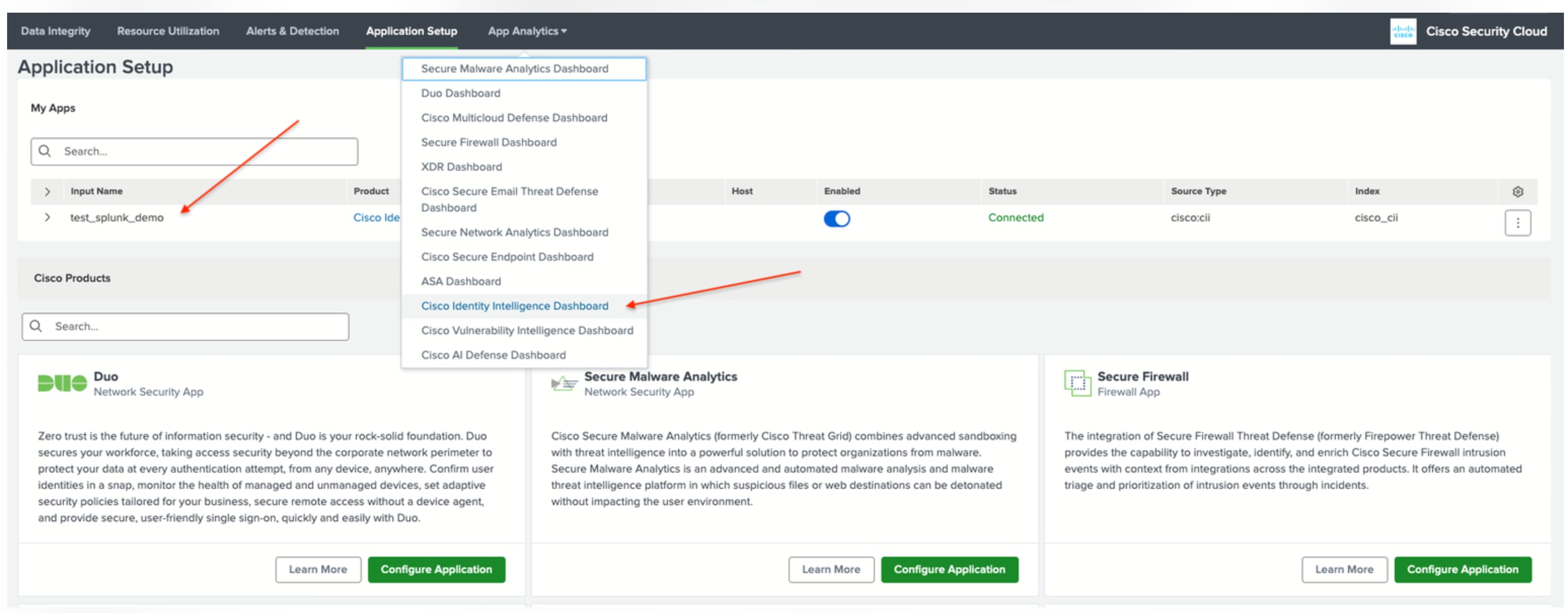
  1. Navigate to Splunk and ensure the test application (test_splunk_demo) is listed in the My Apps table.

  2. Go to App Analytics and select the Cisco Identity Intelligence Dashboard from the list of available dashboards.

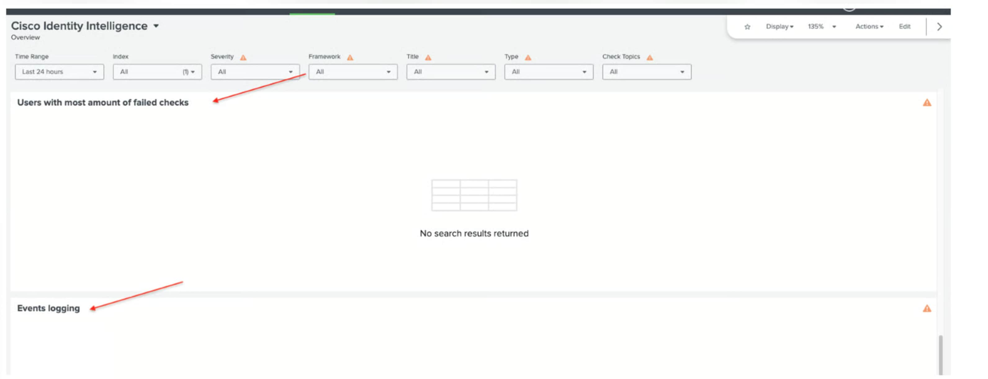
  3. Check the dashboard data. Filter the data by index if you used a unique index during the setup process.

    Note

     
    If this is your first time using the dashboard, it is expected that no data will be displayed.

Step 2

In Cisco Identity Intelligence (CII)

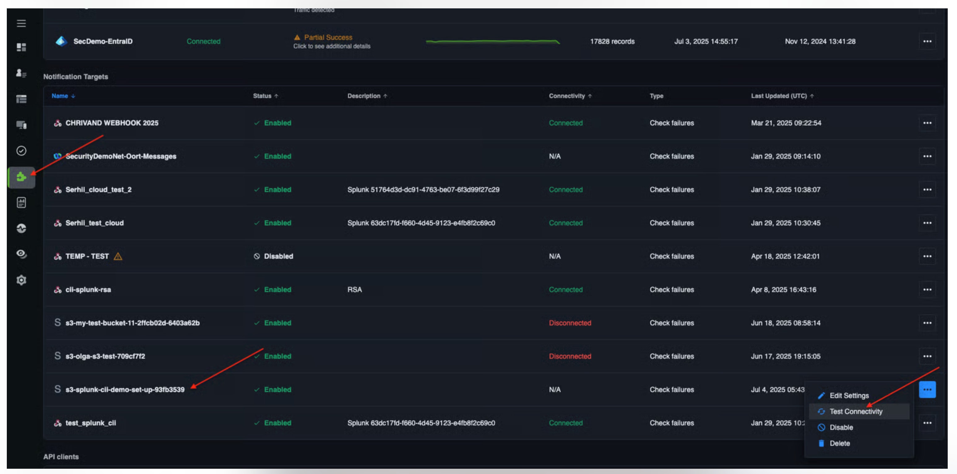
  1. Navigate to Cisco Identity Intelligence and navigate to the Integrations section.

  2. Under Notifications Targets table locate the integration entry:

    1. If you are using Webhook, search for the input named test_splunk_demo

    2. If you are using AWS S3, search for the input name s3-splunk-cii-demo-set-up (or s3-<name of your AWS bucket>)

  3. Click on the three dots (menu icon) next to the integration entry.

  4. Select Test Connectivity from the menu options.

    A popup appears indicating the status Success


What to do next

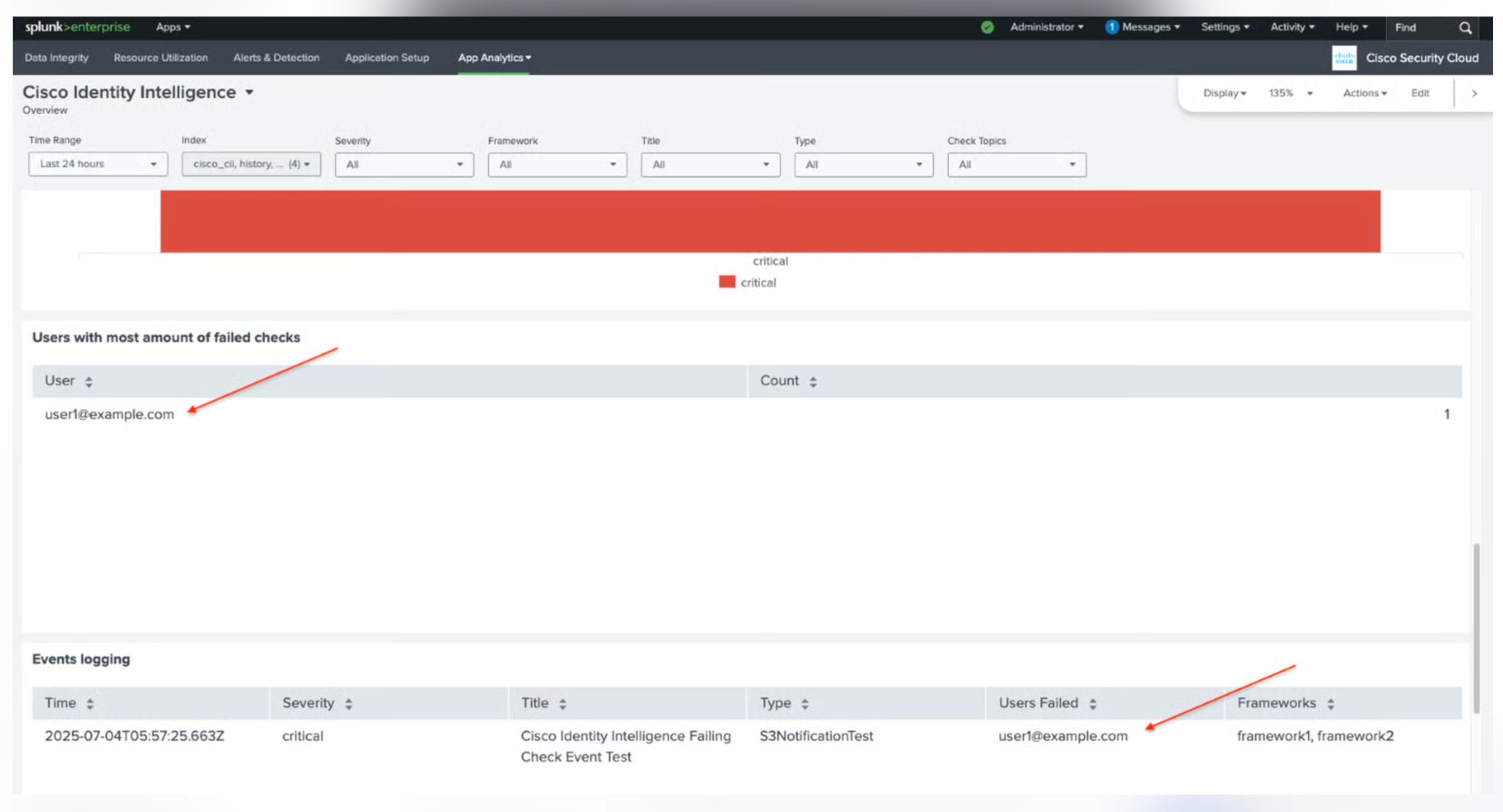
  1. Navigate to the Cisco Identity Intelligence Dashboard in Splunk.

  2. Confirm that the test event triggered during connectivity testing is visible in the dashboard.