- About This Guide
-
- Information about AAA
- Configuring the Local Database for AAA
- Configuring RADIUS Servers for AAA
- Configuring TACACS+ Servers for AAA
- Configuring LDAP Servers for AAA
- Configuring Windows NT Servers for AAA
- Configuring the Identity Firewall
- Configuring the ASA to Integrate with Cisco TrustSec
- Configuring Digital Certificates
- Index
- Information About Completing Interface Configuration in Routed Mode
- Licensing Requirements for Completing Interface Configuration in Routed Mode
- Guidelines and Limitations
- Default Settings
- Completing Interface Configuration in Routed Mode
- Turning Off and Turning On Interfaces
- Monitoring Interfaces
Completing Interface Configuration (Routed Mode)
This chapter includes tasks to complete the interface configuration for all models in routed firewall mode. This chapter includes the following sections:
- Information About Completing Interface Configuration in Routed Mode
- Licensing Requirements for Completing Interface Configuration in Routed Mode
- Guidelines and Limitations
- Default Settings
- Completing Interface Configuration in Routed Mode
- Turning Off and Turning On Interfaces
- Monitoring Interfaces
- Feature History for Interfaces in Routed Mode

Note![]() For multiple context mode, complete the tasks in this section in the context execution space. In the Configuration > Device List pane, double-click the context name under the active device IP address.
For multiple context mode, complete the tasks in this section in the context execution space. In the Configuration > Device List pane, double-click the context name under the active device IP address.
Information About Completing Interface Configuration in Routed Mode
This section includes the following topics:
Security Levels
Each interface must have a security level from 0 (lowest) to 100 (highest). For example, you should assign your most secure network, such as the inside host network, to level 100. While the outside network connected to the Internet can be level 0. Other networks, such as DMZs can be in between. You can assign interfaces to the same security level. See the “Allowing Same Security Level Communication” section for more information.
The level controls the following behavior:
- Network access—By default, there is an implicit permit from a higher security interface to a lower security interface (outbound). Hosts on the higher security interface can access any host on a lower security interface. You can limit access by applying an ACL to the interface.
If you enable communication for same security interfaces (see the “Allowing Same Security Level Communication” section), there is an implicit permit for interfaces to access other interfaces on the same security level or lower.
- Inspection engines—Some application inspection engines are dependent on the security level. For same security interfaces, inspection engines apply to traffic in either direction.
–![]() NetBIOS inspection engine—Applied only for outbound connections.
NetBIOS inspection engine—Applied only for outbound connections.
–![]() SQL*Net inspection engine—If a control connection for the SQL*Net (formerly OraServ) port exists between a pair of hosts, then only an inbound data connection is permitted through the ASA.
SQL*Net inspection engine—If a control connection for the SQL*Net (formerly OraServ) port exists between a pair of hosts, then only an inbound data connection is permitted through the ASA.
- Filtering—HTTP(S) and FTP filtering applies only for outbound connections (from a higher level to a lower level).
If you enable communication for same security interfaces, you can filter traffic in either direction.
- established command—This command allows return connections from a lower security host to a higher security host if there is already an established connection from the higher level host to the lower level host.
If you enable communication for same security interfaces, you can configure established commands for both directions.
Dual IP Stack (IPv4 and IPv6)
The ASA supports the configuration of both IPv6 and IPv4 on an interface. You do not need to enter any special commands to do so; simply enter the IPv4 configuration commands and IPv6 configuration commands as you normally would. Make sure you configure a default route for both IPv4 and IPv6.
Licensing Requirements for Completing Interface Configuration in Routed Mode
|
|
|
|---|---|
VLANs1: Base License—All interfaces Fast Ethernet. Security Plus License—Ethernet 0/0 and 0/1: Gigabit Ethernet; all others Fast Ethernet. Interfaces of all types2: |
|
VLANs 1 : Interfaces of all types 2 : |
|
VLANs 1 : Interfaces of all types 2 : |
|
VLANs 1 : Interfaces of all types 2 : |
|
VLANs 1 : Interfaces of all types 2 : |
|
VLANs 1 : Interfaces of all types 2 : |
|
VLANs 1 : Interfaces of all types 2 : |
|
VLANs 1 : Interfaces of all types 2 : |
|
VLANs 1 : Interfaces of all types 2 : |
|
VLANs 1 : Interfaces of all types 2 : |
|
VLANs 1 : Base and Security Plus License: 1024 Interface Speed for SSP-10 and SSP-20: Base License—1-Gigabit Ethernet for fiber interfaces 10 GE I/O License (Security Plus)—10-Gigabit Ethernet for fiber interfaces (SSP-40 and SSP-60 support 10-Gigabit Ethernet by default.) Interfaces of all types 2 : |
|
|
|
|---|---|
Guidelines and Limitations
This section includes the guidelines and limitations for this feature.
- For the ASA 5510 and higher in multiple context mode, configure the physical interfaces in the system execution space according to Chapter11, “Starting Interface Configuration (ASA 5510 and Higher)” Then, configure the logical interface parameters in the context execution space according to this chapter. For the ASASM in multiple context mode, configure switch ports and VLANs on the switch, and then assign VLANs to the ASASM according to Chapter2, “Configuring the Switch for Use with the ASA Services Module”
The ASA 5505 does not support multiple context mode.
- In multiple context mode, you can only configure context interfaces that you already assigned to the context in the system configuration according to the “Configuring Multiple Contexts” section.
- PPPoE is not supported in multiple context mode.
Supported in routed firewall mode. For transparent mode, see Chapter14, “Completing Interface Configuration (Transparent Mode, 8.4 and Later)”
Do not finish configuring failover interfaces with the procedures in this chapter. See “Configuring Failover,” to configure the failover and state links. In multiple context mode, failover interfaces are configured in the system configuration.
VLAN ID Guidelines for the ASASM
You can add any VLAN ID to the configuration, but only VLANs that are assigned to the ASA by the switch can pass traffic. To view all VLANs assigned to the ASA, use the show vlan command.
If you add an interface for a VLAN that is not yet assigned to the ASA by the switch, the interface will be in the down state. When you assign the VLAN to the ASA, the interface changes to an up state. See the show interface command for more information about interface states.
Default Settings
This section lists default settings for interfaces if you do not have a factory default configuration. For information about the factory default configurations, see the “Factory Default Configurations” section.
The default security level is 0. If you name an interface “inside” and you do not set the security level explicitly, then the ASA sets the security level to 100.
Note![]() If you change the security level of an interface, and you do not want to wait for existing connections to time out before the new security information is used, you can clear the connections using the clear local-host command.
If you change the security level of an interface, and you do not want to wait for existing connections to time out before the new security information is used, you can clear the connections using the clear local-host command.
Default State of Interfaces for the ASASM
- In single mode or in the system execution space, VLAN interfaces are enabled by default.
- In multiple context mode, all allocated interfaces are enabled by default, no matter what the state of the interface is in the system execution space. However, for traffic to pass through the interface, the interface also has to be enabled in the system execution space. If you shut down an interface in the system execution space, then that interface is down in all contexts that share it.
By default, the ASASM supports jumbo frames. Just configure the MTU for the desired packet size according to the “Configuring the MAC Address, MTU, and TCP MSS” section.
Completing Interface Configuration in Routed Mode
This section includes the following topics:
- Task Flow for Completing Interface Configuration
- Configuring General Interface Parameters
- Configuring the MAC Address, MTU, and TCP MSS
- Configuring IPv6 Addressing
- Allowing Same Security Level Communication
Task Flow for Completing Interface Configuration
Step 1![]() Set up your interfaces depending on your model:
Set up your interfaces depending on your model:
- ASA 5510 and higher—Chapter11, “Starting Interface Configuration (ASA 5510 and Higher)”
- ASA 5505—Chapter12, “Starting Interface Configuration (ASA 5505)”
- ASASM—Chapter2, “Configuring the Switch for Use with the ASA Services Module”
Step 2![]() (Multiple context mode) Allocate interfaces to the context according to the “Configuring Multiple Contexts” section.
(Multiple context mode) Allocate interfaces to the context according to the “Configuring Multiple Contexts” section.
Step 3![]() (Multiple context mode) In the Configuration > Device List pane, double-click the context name under the active device IP address.
(Multiple context mode) In the Configuration > Device List pane, double-click the context name under the active device IP address.
Step 4![]() Configure general interface parameters, including the interface name, security level, and IPv4 address. See the “Configuring General Interface Parameters” section.
Configure general interface parameters, including the interface name, security level, and IPv4 address. See the “Configuring General Interface Parameters” section.
Step 5![]() (Optional) Configure the MAC address and the MTU. See the “Configuring the MAC Address, MTU, and TCP MSS” section.
(Optional) Configure the MAC address and the MTU. See the “Configuring the MAC Address, MTU, and TCP MSS” section.
Step 6![]() (Optional) Configure IPv6 addressing. See the “Configuring IPv6 Addressing” section.
(Optional) Configure IPv6 addressing. See the “Configuring IPv6 Addressing” section.
Step 7![]() (Optional) Allow same security level communication, either by allowing communication between two interfaces or by allowing traffic to enter and exit the same interface. See the “Allowing Same Security Level Communication” section.
(Optional) Allow same security level communication, either by allowing communication between two interfaces or by allowing traffic to enter and exit the same interface. See the “Allowing Same Security Level Communication” section.
Configuring General Interface Parameters
This procedure describes how to set the name, security level, IPv4 address and other options.
For the ASA 5510 and higher, you must configure interface parameters for the following interface types:
For the ASA 5505 and ASASM, you must configure interface parameters for the following interface types:
Guidelines and Limitations
- For the ASA 5550, for maximum throughput, be sure to balance your traffic over the two interface slots; for example, assign the inside interface to slot 1 and the outside interface to slot 0.
- If you are using failover, do not use this procedure to name interfaces that you are reserving for failover and Stateful Failover communications. See “Configuring Failover,” to configure the failover and state links.
Restrictions
Prerequisites
–![]() ASA 5510 and higher—Chapter11, “Starting Interface Configuration (ASA 5510 and Higher)”
ASA 5510 and higher—Chapter11, “Starting Interface Configuration (ASA 5510 and Higher)”
–![]() ASA 5505—Chapter12, “Starting Interface Configuration (ASA 5505)”
ASA 5505—Chapter12, “Starting Interface Configuration (ASA 5505)”
–![]() ASASM—Chapter2, “Configuring the Switch for Use with the ASA Services Module”
ASASM—Chapter2, “Configuring the Switch for Use with the ASA Services Module”
- In multiple context mode, you can only configure context interfaces that you already assigned to the context in the system configuration according to the “Configuring Multiple Contexts” section.
- In multiple context mode, complete this procedure in the context execution space. To change from the system to a context configuration, in the Configuration > Device List pane, double-click the context name under the active device IP address.
Detailed Steps
Step 1![]() Choose the Configuration > Device Setup > Interfaces pane.
Choose the Configuration > Device Setup > Interfaces pane.
For the ASA 5505, the Interfaces tab shows by default.
Step 2![]() Choose the interface row, and click Edit .
Choose the interface row, and click Edit .
The Edit Interface dialog box appears with the General tab selected.
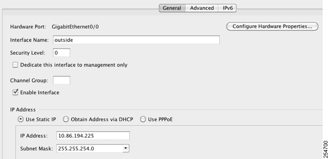
Step 3![]() In the Interface Name field, enter a name up to 48 characters in length.
In the Interface Name field, enter a name up to 48 characters in length.
Step 4![]() In the Security level field, enter a level between 0 (lowest) and 100 (highest).
In the Security level field, enter a level between 0 (lowest) and 100 (highest).
See the “Security Levels” section for more information.
Step 5![]() (Optional; not supported for redundant interfaces) To set this interface as a management-only interface, check the Dedicate this interface to management-only check box.
(Optional; not supported for redundant interfaces) To set this interface as a management-only interface, check the Dedicate this interface to management-only check box.
Through traffic is not accepted on a management-only interface. For the ASA 5510 and higher, see the “Prerequisites” section for more information.
(ASA 5512-X through ASA 5555-X) You cannot disable this option on the Management 0/0 interface.
Note The Channel Group field is read-only and indicates if the interface is part of an EtherChannel.
Step 6![]() If the interface is not already enabled, check the Enable Interface check box.
If the interface is not already enabled, check the Enable Interface check box.
Step 7![]() To set the IP address, one of the following options.
To set the IP address, one of the following options.
Note For use with failover, you must set the IP address and standby address manually; DHCP and PPPoE are not supported. Set the standby IP addresses on the Configuration > Device Management > High Availability > Failover > Interfaces tab.
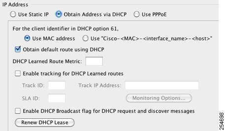
a.![]() To force a MAC address to be stored inside a DHCP request packet for option 61, click the Use MAC Address radio button.
To force a MAC address to be stored inside a DHCP request packet for option 61, click the Use MAC Address radio button.
Some ISPs expect option 61 to be the interface MAC address. If the MAC address is not included in the DHCP request packet, then an IP address will not be assigned.
b.![]() To use a generated string for option 61, click Use “Cisco-<MAC>-<interface_name>-<host>” .
To use a generated string for option 61, click Use “Cisco-<MAC>-<interface_name>-<host>” .
c.![]() (Optional) To obtain the default route from the DHCP server, check Obtain Default Route Using DHCP .
(Optional) To obtain the default route from the DHCP server, check Obtain Default Route Using DHCP .
d.![]() (Optional) To assign an administrative distance to the learned route, enter a value between 1 and 255 in the DHCP Learned Route Metric field. If this field is left blank, the administrative distance for the learned routes is 1.
(Optional) To assign an administrative distance to the learned route, enter a value between 1 and 255 in the DHCP Learned Route Metric field. If this field is left blank, the administrative distance for the learned routes is 1.
e.![]() (Optional) To enable tracking for DHCP-learned routes, check Enable Tracking for DHCP Learned Routes . Set the following values:
(Optional) To enable tracking for DHCP-learned routes, check Enable Tracking for DHCP Learned Routes . Set the following values:
Track ID—A unique identifier for the route tracking process. Valid values are from 1 to 500.
Track IP Address—Enter the IP address of the target being tracked. Typically, this would be the IP address of the next hop gateway for the route, but it could be any network object available off of that interface.
Note Route tracking is only available in single, routed mode.
SLA ID—A unique identifier for the SLA monitoring process. Valid values are from 1 to 2147483647.
Monitor Options—Click this button to open the Route Monitoring Options dialog box. In the Route Monitoring Options dialog box you can configure the parameters of the tracked object monitoring process.
f.![]() (Optional) To set the broadcast flag to 1 in the DHCP packet header when the DHCP client sends a discover requesting an IP address, check Enable DHCP Broadcast flag for DHCP request and discover messages .
(Optional) To set the broadcast flag to 1 in the DHCP packet header when the DHCP client sends a discover requesting an IP address, check Enable DHCP Broadcast flag for DHCP request and discover messages .
The DHCP server listens to this broadcast flag and broadcasts the reply packet if the flag is set to 1.
g.![]() (Optional) To renew the lease, click Renew DHCP Lease .
(Optional) To renew the lease, click Renew DHCP Lease .
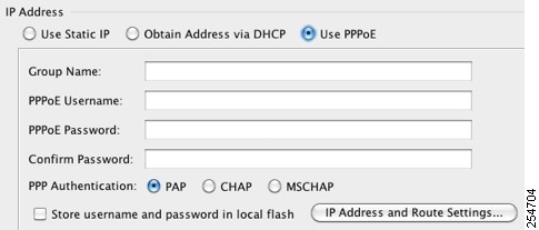
a.![]() In the Group Name field, specify a group name.
In the Group Name field, specify a group name.
b.![]() In the PPPoE Username field, specify the username provided by your ISP.
In the PPPoE Username field, specify the username provided by your ISP.
c.![]() In the PPPoE Password field, specify the password provided by your ISP.
In the PPPoE Password field, specify the password provided by your ISP.
d.![]() In the Confirm Password field, retype the password.
In the Confirm Password field, retype the password.
e.![]() For PPP authentication, click either the PAP , CHAP , or MSCHAP radio button.
For PPP authentication, click either the PAP , CHAP , or MSCHAP radio button.
PAP passes cleartext username and password during authentication and is not secure. With CHAP, the client returns the encrypted [challenge plus password], with a cleartext username in response to the server challenge. CHAP is more secure than PAP, but it does not encrypt data. MSCHAP is similar to CHAP but is more secure because the server stores and compares only encrypted passwords rather than cleartext passwords as in CHAP. MSCHAP also generates a key for data encryption by MPPE.
f.![]() (Optional) To store the username and password in Flash memory, check the Store Username and Password in Local Flash check box.
(Optional) To store the username and password in Flash memory, check the Store Username and Password in Local Flash check box.
The ASA stores the username and password in a special location of NVRAM. If an Auto Update Server sends a clear configure command to the ASA, and the connection is then interrupted, the ASA can read the username and password from NVRAM and re-authenticate to the Access Concentrator.
g.![]() (Optional) To display the PPPoE IP Address and Route Settings dialog box where you can choose addressing and tracking options, click IP Address and Route Settings . See the “PPPoE IP Address and Route Settings” section for more information.
(Optional) To display the PPPoE IP Address and Route Settings dialog box where you can choose addressing and tracking options, click IP Address and Route Settings . See the “PPPoE IP Address and Route Settings” section for more information.
Step 8![]() (Optional) In the Description field, enter a description for this interface.
(Optional) In the Description field, enter a description for this interface.
The description can be up to 240 characters on a single line, without carriage returns. In the case of a failover or state link, the description is fixed as “LAN Failover Interface,” “STATE Failover Interface,” or “LAN/STATE Failover Interface,” for example. You cannot edit this description. The fixed description overwrites any description you enter here if you make this interface a failover or state link.
Note (ASA 5510 and higher) For information about the Configure Hardware Properties button, see the “Enabling the Physical Interface and Configuring Ethernet Parameters” section.
What to Do Next
- (Optional) Configure the MAC address and the MTU. See the “Configuring the MAC Address, MTU, and TCP MSS” section.
- (Optional) Configure IPv6 addressing. See the “Configuring IPv6 Addressing” section.
PPPoE IP Address and Route Settings
The Configuration > Interfaces > Add/Edit Interface > General > PPPoE IP Address and Route Settings > PPPoE IP Address and Route Settings dialog box lets you choose addressing and tracking options for PPPoE connections.
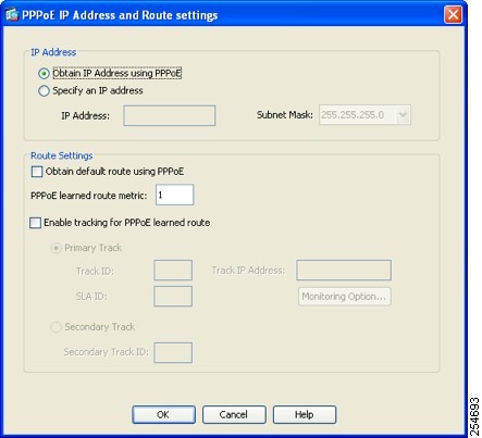
- IP Address area—Lets you choose between Obtaining an IP address using PPP or specifying an IP address, and contains the following fields:
–![]() Obtain IP Address using PPP—Select to enable the ASA to use PPP to get an IP address.
Obtain IP Address using PPP—Select to enable the ASA to use PPP to get an IP address.
–![]() Specify an IP Address—Specify an IP address and mask for the ASA to use instead of negotiating with the PPPoE server to assign an address dynamically.
Specify an IP Address—Specify an IP address and mask for the ASA to use instead of negotiating with the PPPoE server to assign an address dynamically.
- Route Settings Area—Lets you configure route and tracking settings and contains the following fields:
–![]() Obtain default route using PPPoE—Sets the default routes when the PPPoE client has not yet established a connection. When using this option, you cannot have a statically defined route in the configuration.
Obtain default route using PPPoE—Sets the default routes when the PPPoE client has not yet established a connection. When using this option, you cannot have a statically defined route in the configuration.
PPPoE learned route metric—Assigns an administrative distance to the learned route. Valid values are from 1 to 255. If this field is left blank, the administrative distance for the learned routes is 1.
–![]() Enable tracking—Check this check box to enable route tracking for PPPoE-learned routes.
Enable tracking—Check this check box to enable route tracking for PPPoE-learned routes.
Note Route tracking is only available in single, routed mode.
–![]() Primary Track—Select this option to configure the primary PPPoE route tracking.
Primary Track—Select this option to configure the primary PPPoE route tracking.
–![]() Track ID—A unique identifier for the route tracking process. Valid values are from 1 to 500.
Track ID—A unique identifier for the route tracking process. Valid values are from 1 to 500.
–![]() Track IP Address—Enter the IP address of the target being tracked. Typically, this would be the IP address of the next hop gateway for the route, but it could be any network object available off of that interface.
Track IP Address—Enter the IP address of the target being tracked. Typically, this would be the IP address of the next hop gateway for the route, but it could be any network object available off of that interface.
–![]() SLA ID—A unique identifier for the SLA monitoring process. Valid values are from 1 to 2147483647.
SLA ID—A unique identifier for the SLA monitoring process. Valid values are from 1 to 2147483647.
–![]() Monitor Options—Click this button to open the Route Monitoring Options dialog box. In the Route Monitoring Options dialog box you can configure the parameters of the tracked object monitoring process.
Monitor Options—Click this button to open the Route Monitoring Options dialog box. In the Route Monitoring Options dialog box you can configure the parameters of the tracked object monitoring process.
–![]() Secondary Track—Select this option to configure the secondary PPPoE route tracking.
Secondary Track—Select this option to configure the secondary PPPoE route tracking.
–![]() Secondary Track ID—A unique identifier for the route tracking process. Valid values are from 1 to 500.
Secondary Track ID—A unique identifier for the route tracking process. Valid values are from 1 to 500.
Configuring the MAC Address, MTU, and TCP MSS
This section describes how to configure MAC addresses for interfaces, how to set the MTU, and set the TCP MSS.
Information About MAC Addresses
By default, the physical interface uses the burned-in MAC address, and all subinterfaces of a physical interface use the same burned-in MAC address.
For the ASASM, all VLANs use the same MAC address provided by the backplane.
A redundant interface uses the MAC address of the first physical interface that you add. If you change the order of the member interfaces in the configuration, then the MAC address changes to match the MAC address of the interface that is now listed first. If you assign a MAC address to the redundant interface using this command, then it is used regardless of the member interface MAC addresses.
For an EtherChannel, all interfaces that are part of the channel group share the same MAC address. This feature makes the EtherChannel transparent to network applications and users, because they only see the one logical connection; they have no knowledge of the individual links. The port-channel interface uses the lowest numbered channel group interface MAC address as the port-channel MAC address. Alternatively you can manually configure a MAC address for the port-channel interface. In multiple context mode, you can automatically assign unique MAC addresses to interfaces, including an EtherChannel port interface. We recommend manually, or in multiple context mode, automatically configuring a unique MAC address in case the group channel interface membership changes. If you remove the interface that was providing the port-channel MAC address, then the port-channel MAC address changes to the next lowest numbered interface, thus causing traffic disruption.
In multiple context mode, if you share an interface between contexts, you can assign a unique MAC address to the interface in each context. This feature lets the ASA easily classify packets into the appropriate context. Using a shared interface without unique MAC addresses is possible, but has some limitations. See the “How the ASA Classifies Packets” section for more information. You can assign each MAC address manually, or you can automatically generate MAC addresses for shared interfaces in contexts. See the “Automatically Assigning MAC Addresses to Context Interfaces” section to automatically generate MAC addresses. If you automatically generate MAC addresses, you can use this procedure to override the generated address.
For single context mode, or for interfaces that are not shared in multiple context mode, you might want to assign unique MAC addresses to subinterfaces. For example, your service provider might perform access control based on the MAC address.
Information About the MTU and TCP MSS
See the “Controlling Fragmentation with the Maximum Transmission Unit and TCP Maximum Segment Size” section.
Prerequisites
–![]() ASA 5510 and higher—Chapter11, “Starting Interface Configuration (ASA 5510 and Higher)”
ASA 5510 and higher—Chapter11, “Starting Interface Configuration (ASA 5510 and Higher)”
–![]() ASA 5505—Chapter12, “Starting Interface Configuration (ASA 5505)”
ASA 5505—Chapter12, “Starting Interface Configuration (ASA 5505)”
–![]() ASASM—Chapter2, “Configuring the Switch for Use with the ASA Services Module”
ASASM—Chapter2, “Configuring the Switch for Use with the ASA Services Module”
- In multiple context mode, you can only configure context interfaces that you already assigned to the context in the system configuration according to the “Configuring Multiple Contexts” section.
- In multiple context mode, complete this procedure in the context execution space. To change from the system to a context configuration, in the Configuration > Device List pane, double-click the context name under the active device IP address.
Detailed Steps
Step 1![]() Choose the Configuration > Device Setup > Interfaces pane.
Choose the Configuration > Device Setup > Interfaces pane.
For the ASA 5505, the Interfaces tab shows by default.
Step 2![]() Choose the interface row, and click Edit .
Choose the interface row, and click Edit .
The Edit Interface dialog box appears with the General tab selected.
Step 3![]() Click the Advanced tab.
Click the Advanced tab.
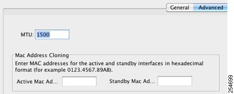
Step 4![]() To set the MTU or to enable jumbo frame support (supported models only), enter the value in the MTU field, between 300 and 65,535 bytes.
To set the MTU or to enable jumbo frame support (supported models only), enter the value in the MTU field, between 300 and 65,535 bytes.
Note When you set the MTU for a redundant or port-channel interface, the ASA applies the setting to all member interfaces.
- For models that support jumbo frames in single mode—If you enter a value for any interface that is greater than 1500, then you enable jumbo frame support automatically for all interfaces. If you set the MTU for all interfaces back to a value under 1500, then jumbo frame support is disabled.
- For models that support jumbo frames in multiple mode—If you enter a value for any interface that is greater than 1500, then be sure to enable jumbo frame support in the system configuration. See the “Enabling Jumbo Frame Support (Supported Models)” section.
Note Enabling or disabling jumbo frame support requires you to reload the ASA.
Step 5![]() To manually assign a MAC address to this interface, enter a MAC address in the Active Mac Address field in H.H.H format, where H is a 16-bit hexadecimal digit.
To manually assign a MAC address to this interface, enter a MAC address in the Active Mac Address field in H.H.H format, where H is a 16-bit hexadecimal digit.
For example, the MAC address 00-0C-F1-42-4C-DE would be entered as 000C.F142.4CDE. The first two bytes of a manual MAC address cannot be A2 if you also want to use auto-generated MAC addresses.
Step 6![]() If you use failover, enter the standby MAC address in the Standby Mac Address field. If the active unit fails over and the standby unit becomes active, the new active unit starts using the active MAC addresses to minimize network disruption, while the old active unit uses the standby address.
If you use failover, enter the standby MAC address in the Standby Mac Address field. If the active unit fails over and the standby unit becomes active, the new active unit starts using the active MAC addresses to minimize network disruption, while the old active unit uses the standby address.
Step 7![]() To set the TCP MSS, choose Configuration > Firewall > Advanced > TCP Options . Set the following options:
To set the TCP MSS, choose Configuration > Firewall > Advanced > TCP Options . Set the following options:
- Force Maximum Segment Size for TCP—Sets the maximum TCP segment size in bytes, between 48 and any maximum number. The default value is 1380 bytes. You can disable this feature by setting the bytes to 0.
- Force Minimum Segment Size for TCP — Overrides the maximum segment size to be no less than the number of bytes you set, between 48 and any maximum number. This feature is disabled by default (set to 0).
What to Do Next
(Optional) Configure IPv6 addressing. See the “Configuring IPv6 Addressing” section.
Configuring IPv6 Addressing
This section describes how to configure IPv6 addressing. For more information about IPv6, see the “IPv6 Addresses” section.
Information About IPv6
This section includes information about how to configure IPv6, and includes the following topics:
IPv6 Addressing
You can configure two types of unicast addresses for IPv6:
- Global—The global address is a public address that you can use on the public network.
- Link-local—The link-local address is a private address that you can only use on the directly-connected network. Routers do not forward packets using link-local addresses; they are only for communication on a particular physical network segment. They can be used for address configuration or for the ND functions such as address resolution and neighbor discovery.
At a minimum, you need to configure a link-local address for IPv6 to operate. If you configure a global address, a link-local address is automatically configured on the interface, so you do not also need to specifically configure a link-local address. If you do not configure a global address, then you need to configure the link-local address, either automatically or manually.
Modified EUI-64 Interface IDs
RFC 3513: Internet Protocol Version 6 (IPv6) Addressing Architecture requires that the interface identifier portion of all unicast IPv6 addresses, except those that start with binary value 000, be 64 bits long and be constructed in Modified EUI-64 format. The ASA can enforce this requirement for hosts attached to the local link.
When this feature is enabled on an interface, the source addresses of IPv6 packets received on that interface are verified against the source MAC addresses to ensure that the interface identifiers use the Modified EUI-64 format. If the IPv6 packets do not use the Modified EUI-64 format for the interface identifier, the packets are dropped and the following system log message is generated:
The address format verification is only performed when a flow is created. Packets from an existing flow are not checked. Additionally, the address verification can only be performed for hosts on the local link. Packets received from hosts behind a router will fail the address format verification, and be dropped, because their source MAC address will be the router MAC address and not the host MAC address.
Configuring a Global IPv6 Address
To configure a global IPv6 address, perform the following steps.
Note![]() Configuring the global address automatically configures the link-local address, so you do not need to configure it separately.
Configuring the global address automatically configures the link-local address, so you do not need to configure it separately.
Restrictions
Prerequisites
–![]() ASA 5510 and higher—Chapter11, “Starting Interface Configuration (ASA 5510 and Higher)”
ASA 5510 and higher—Chapter11, “Starting Interface Configuration (ASA 5510 and Higher)”
–![]() ASA 5505—Chapter12, “Starting Interface Configuration (ASA 5505)”
ASA 5505—Chapter12, “Starting Interface Configuration (ASA 5505)”
–![]() ASASM—Chapter2, “Configuring the Switch for Use with the ASA Services Module”
ASASM—Chapter2, “Configuring the Switch for Use with the ASA Services Module”
- In multiple context mode, you can only configure context interfaces that you already assigned to the context in the system configuration according to the “Configuring Multiple Contexts” section.
- In multiple context mode, complete this procedure in the context execution space. To change from the system to a context configuration, in the Configuration > Device List pane, double-click the context name under the active device IP address.
Detailed Steps
Step 1![]() Choose the Configuration > Device Setup > Interfaces pane.
Choose the Configuration > Device Setup > Interfaces pane.
Step 2![]() Choose an interface, and click Edit .
Choose an interface, and click Edit .
The Edit Interface dialog box appears with the General tab selected.
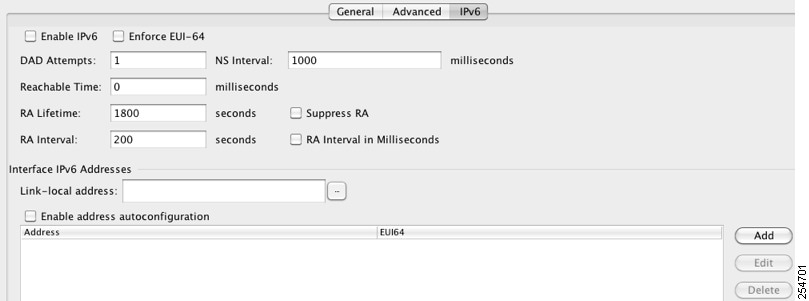
Step 4![]() Check the Enable IPv6 check box.
Check the Enable IPv6 check box.
Step 5![]() (Optional) To enforce the use of Modified EUI-64 format interface identifiers in IPv6 addresses on a local link, check the Enforce EUI-64 check box.
(Optional) To enforce the use of Modified EUI-64 format interface identifiers in IPv6 addresses on a local link, check the Enforce EUI-64 check box.
See the “Modified EUI-64 Interface IDs” section for more information.
Step 6![]() (Optional) In the top area, customize the IPv6 configuration by referring to Chapter31, “Configuring IPv6 Neighbor Discovery”
(Optional) In the top area, customize the IPv6 configuration by referring to Chapter31, “Configuring IPv6 Neighbor Discovery”
Step 7![]() Configure the global IPv6 address using one of the following methods.
Configure the global IPv6 address using one of the following methods.
Enabling stateless autconfiguration on the interface configures IPv6 addresses based upon prefixes received in Router Advertisement messages. A link-local address, based on the Modified EUI-64 interface ID, is automatically generated for the interface when stateless autoconfiguration is enabled.
Note Although RFC 4862 specifies that hosts configured for stateless autoconfiguration do not send Router Advertisement messages, the ASA does send Router Advertisement messages in this case. See the Suppress RA chck box to suppress messages.
a.![]() In the Interface IPv6 Addresses area, click Add .
In the Interface IPv6 Addresses area, click Add .
The Add IPv6 Address for Interface dialog box appears.
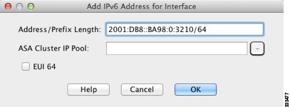
b.![]() In the Address/Prefix Length field, enter either full global IPv6 address, including the interface ID, or enter the IPv6 prefix, along with the IPv6 prefix length. If you only enter the prefix, then be sure to check the EUI 64 checkbox to generate the interface ID using the Modified EUI-64 format. For example, 2001:0DB8::BA98:0:3210/48 (full address) or 2001:0DB8::/48 (prefix, with EUI 64 checked). See the “IPv6 Addresses” section for more information about IPv6 addressing.
In the Address/Prefix Length field, enter either full global IPv6 address, including the interface ID, or enter the IPv6 prefix, along with the IPv6 prefix length. If you only enter the prefix, then be sure to check the EUI 64 checkbox to generate the interface ID using the Modified EUI-64 format. For example, 2001:0DB8::BA98:0:3210/48 (full address) or 2001:0DB8::/48 (prefix, with EUI 64 checked). See the “IPv6 Addresses” section for more information about IPv6 addressing.
Note For information about the ASA Cluster IP Pool, see the “Configuring Individual Interfaces (Recommended for the Management Interface)” section.
Step 8![]() (Optional) To configure which IPv6 prefixes are included in IPv6 router advertisements, refer to the “Configuring the IPv6 Prefix in Router Advertisements” section.
(Optional) To configure which IPv6 prefixes are included in IPv6 router advertisements, refer to the “Configuring the IPv6 Prefix in Router Advertisements” section.
You return to the Configuration > Device Setup > Interfaces pane.
Configuring IPv6 Neighbor Discovery
See “Configuring IPv6 Neighbor Discovery,” to configure IPv6 neighbor discovery.
(Optional) Configuring the Link-Local Addresses Automatically
If you do not want to configure a global address, and only need to configure a link-local address, you have the option of generating the link-local addresses based on the interface MAC addresses (Modified EUI-64 format. Because MAC addresses use 48 bits, additional bits must be inserted to fill the 64 bits required for the interface ID.)
To manually assign the link-local address (not recommended), see the “(Optional) Configuring the Link-Local Addresses Manually” section.
For other IPv6 options, including enforcing the Modified EUI-64 format, and DAD settings, see the “Configuring a Global IPv6 Address” section.
To automatically configure the link-local addresses for an interface, perform the following steps:
Step 1![]() Choose the Configuration > Device Setup > Interfaces pane.
Choose the Configuration > Device Setup > Interfaces pane.
Step 2![]() Select an interface, and click Edit .
Select an interface, and click Edit .
The Edit Interface dialog box appears with the General tab selected.
Step 4![]() In the IPv6 configuration area, check the Enable IPv6 check box.
In the IPv6 configuration area, check the Enable IPv6 check box.
This option enables IPv6 and automatically generates the link-local address using the Modified EUI-64 interface ID based on the interface MAC address.
(Optional) Configuring the Link-Local Addresses Manually
If you do not want to configure a global address, and only need to configure a link-local address, you have the option of manually defining the link-local address. Note that we recommend automatically assigning the link-local address based on the Modified EUI-64 format. For example, if other devices enforce the use of the Modified EUI-64 format, then a manually-assigned link-local address may cause packets to be dropped.
To automatically assign the link-local address (recommended), see the “(Optional) Configuring the Link-Local Addresses Automatically” section.
For other IPv6 options, including enforcing the Modified EUI-64 format, and DAD settings, see the “Configuring a Global IPv6 Address” section.
To assign a link-local address to an interface, perform the following steps:
Step 1![]() Choose the Configuration > Device Setup > Interfaces pane.
Choose the Configuration > Device Setup > Interfaces pane.
Step 2![]() Select an interface, and click Edit .
Select an interface, and click Edit .
The Edit Interface dialog box appears with the General tab selected.
Step 4![]() To set the link-local address, enter an address in the Link-local address field.
To set the link-local address, enter an address in the Link-local address field.
A link-local address should start with FE8, FE9, FEA, or FEB, for example fe80::20d:88ff:feee:6a82. See the “IPv6 Addresses” section for more information about IPv6 addressing.
Allowing Same Security Level Communication
By default, interfaces on the same security level cannot communicate with each other, and packets cannot enter and exit the same interface. This section describes how to enable inter-interface communication when interfaces are on the same security level, and how to enable intra-interface communication.
Information About Inter-Interface Communication
Allowing interfaces on the same security level to communicate with each other provides the following benefits:
If you use different levels for each interface and do not assign any interfaces to the same security level, you can configure only one interface per level (0 to 100).
If you enable same security interface communication, you can still configure interfaces at different security levels as usual.
Information About Intra-Interface Communication
Intra-interface communication might be useful for VPN traffic that enters an interface, but is then routed out the same interface. The VPN traffic might be unencrypted in this case, or it might be reencrypted for another VPN connection. For example, if you have a hub and spoke VPN network, where the ASA is the hub, and remote VPN networks are spokes, for one spoke to communicate with another spoke, traffic must go into the ASA and then out again to the other spoke.
Note![]() All traffic allowed by this feature is still subject to firewall rules. Be careful not to create an asymmetric routing situation that can cause return traffic not to traverse the ASA.
All traffic allowed by this feature is still subject to firewall rules. Be careful not to create an asymmetric routing situation that can cause return traffic not to traverse the ASA.
For the ASASM, before you can enable this feature, you must first correctly configure the MSFC so that packets are sent to the ASA MAC address instead of being sent directly through the switch to the destination host. Figure 13-1 shows a network where hosts on the same interface need to communicate.
Figure 13-1 Communication Between Hosts on the Same Interface
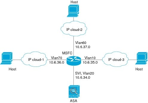
The following sample configuration shows the Cisco IOS route-map commands used to enable policy routing in the network shown in Figure 13-1:
Detailed Steps
- To enable interfaces on the same security level to communicate with each other, from the Configuration > Interfaces pane, check Enable traffic between two or more interfaces which are configured with same security level .
- To enable communication between hosts connected to the same interface, check Enable traffic between two or more hosts connected to the same interface .
Turning Off and Turning On Interfaces
This section describes how to turn off and on an interface.
All interfaces are enabled by default. In multiple context mode, if you disable or reenable the interface within a context, only that context interface is affected. But if you disable or reenable the interface in the system execution space, then you affect that interface for all contexts.
Detailed Steps
Step 1![]() Depending on your context mode:
Depending on your context mode:
By default, all physical interfaces are listed.
Step 2![]() Click a VLAN interface that you want to configure, and click Edit .
Click a VLAN interface that you want to configure, and click Edit .
The Edit Interface dialog box appears.
Step 3![]() To enable or disable the interface, check or uncheck the Enable Interface check box.
To enable or disable the interface, check or uncheck the Enable Interface check box.
Monitoring Interfaces
This section includes the following topics:
ARP Table
The Monitoring > Interfaces > ARP Table pane displays the ARP table, including static and dynamic entries. The ARP table includes entries that map a MAC address to an IP address for a given interface.
- Interface —Lists the interface name associated with the mapping.
- IP Address —Shows the IP address.
- MAC Address —Shows the MAC address.
- Proxy ARP—Displays Yes if proxy ARP is enabled on the interface. Displays No if proxy ARP is not enabled on the interface.
- Clear —Clears the dynamic ARP table entries. Static entries are not cleared.
- Refresh —Refreshes the table with current information from the ASA and updates Last Updated date and time.
- Last Updated — Display only . Shows the date and time the display was updated.
DHCP
The ASA lets you monitor DHCP status, including the addresses assigned to clients, the lease information for the ASA interface, and DHCP statistics.
DHCP Server Table
The Monitoring > Interfaces > DHCP > DHCP Server Table lists the IP addresses assigned to DHCP clients.
- IP Address—Shows the IP address assigned to the client.
- Client-ID—Shows the client MAC address or ID.
- Lease Expiration—Shows the date that the DHCP lease expires. The lease indicates how long the client can use the assigned IP address. Remaining time is also specified in the number of seconds and is based on the timestamp in the Last Updated display-only field.
- Number of Active Leases—Shows the total number of DHCP leases.
- Refresh—Refreshes the information from the ASA.
- Last Updated—Shows when the data in the table was last updated.
DHCP Client Lease Information
If you obtain the ASA interface IP address from a DHCP server, the Monitoring > Interfaces > DHCP > DHCP Server Table > DHCP Client Lease Information pane shows information about the DHCP lease.
- Select an interface—Lists the ASA interfaces. Choose the interface for which you want to view the DHCP lease. If an interface has multiple DHCP leases, then choose the interface and IP address pair you want to view.
- Attribute and Value—Lists the attributes and values of the interface DHCP lease.
–![]() Temp IP addr— Display only . The IP address assigned to the interface.
Temp IP addr— Display only . The IP address assigned to the interface.
–![]() Temp sub net mask— Display only . The subnet mask assigned to the interface.
Temp sub net mask— Display only . The subnet mask assigned to the interface.
–![]() DHCP lease server— Display only . The DHCP server address.
DHCP lease server— Display only . The DHCP server address.
–![]() state— Display only . The state of the DHCP lease, as follows:
state— Display only . The state of the DHCP lease, as follows:
Initial—The initialization state, where the ASA begins the process of acquiring a lease. This state is also shown when a lease ends or when a lease negotiation fails.
Selecting—The ASA is waiting to receive DHCPOFFER messages from one or more DHCP servers, so it can choose one.
Requesting—The ASA is waiting to hear back from the server to which it sent its request.
Purging—The ASA is removing the lease because of an error.
Bound—The ASA has a valid lease and is operating normally.
Renewing—The ASA is trying to renew the lease. It regularly sends DHCPREQUEST messages to the current DHCP server, and waits for a reply.
Rebinding—The ASA failed to renew the lease with the original server, and now sends DHCPREQUEST messages until it gets a reply from any server or the lease ends.
Holddown—The ASA started the process to remove the lease.
Releasing—The ASA sends release messages to the server indicating that the IP address is no longer needed.
–![]() Lease— Display only . The length of time, specified by the DHCP server, that the interface can use this IP address.
Lease— Display only . The length of time, specified by the DHCP server, that the interface can use this IP address.
–![]() Renewal— Display only . The length of time until the interface automatically attempts to renew this lease.
Renewal— Display only . The length of time until the interface automatically attempts to renew this lease.
–![]() Rebind— Display only . The length of time until the ASA attempts to rebind to a DHCP server. Rebinding occurs if the ASA cannot communicate with the original DHCP server, and 87.5 percent of the lease time has expired. The ASA then attempts to contact any available DHCP server by broadcasting DHCP requests.
Rebind— Display only . The length of time until the ASA attempts to rebind to a DHCP server. Rebinding occurs if the ASA cannot communicate with the original DHCP server, and 87.5 percent of the lease time has expired. The ASA then attempts to contact any available DHCP server by broadcasting DHCP requests.
–![]() Next timer fires after— Display only . The number of seconds until the internal timer triggers.
Next timer fires after— Display only . The number of seconds until the internal timer triggers.
–![]() Retry count— Display only . If the ASA is attempting to establish a lease, this field shows the number of times the ASA tried sending a DHCP message. For example, if the ASA is in the Selecting state, this value shows the number of times the ASA sent discover messages. If the ASA is in the Requesting state, this value shows the number of times the ASA sent request messages.
Retry count— Display only . If the ASA is attempting to establish a lease, this field shows the number of times the ASA tried sending a DHCP message. For example, if the ASA is in the Selecting state, this value shows the number of times the ASA sent discover messages. If the ASA is in the Requesting state, this value shows the number of times the ASA sent request messages.
–![]() Client-ID— Display only . The client ID used in all communication with the server.
Client-ID— Display only . The client ID used in all communication with the server.
–![]() Proxy— Display only . Specifies if this interface is a proxy DHCP client for VPN clients, True or False.
Proxy— Display only . Specifies if this interface is a proxy DHCP client for VPN clients, True or False.
DHCP Statistics
The Monitoring > Interfaces > DHCP > DHCP Statistics pane shows statistics for the DHCP server feature.
- Count—Shows the number of times a specific message was processed.
- Direction—Shows if the message type is Sent or Received.
- Total Messages Received—Shows the total number of messages received by the ASA.
- Total Messages Sent—Shows the total number of messages sent by the ASA.
- Counter—Shows general statistical DHCP data, including the following:
MAC Address Table
The Monitoring > Interfaces > MAC Address Table pane shows the static and dynamic MAC address entries. See the “MAC Address Table” section for more information about the MAC address table and adding static entries.
- Interface—Shows the interface name associated with the entry.
- MAC Address—Shows the MAC address.
- Type—Shows if the entry is static or dynamic.
- Age—Shows the age of the entry, in minutes. To set the timeout, see the “MAC Address Table” section .
- Refresh—Refreshes the table with current information from the ASA.
Dynamic ACLs
The Monitoring > Interfaces > Dynamic ACLs pane shows a table of the Dynamic ACLs, which are functionally identical to the user-configured ACLs except that they are created, activated and deleted automatically by the ASA. These ACLs do not show up in the configuration and are only visible in this table. They are identified by the “(dynamic)” keyword in the ACL header.
When you choose an ACL in this table, the contents of the ACL are shown in the bottom text field.
Interface Graphs
The Monitoring > Interfaces > Interface Graphs pane lets you view interface statistics in graph or table form. If an interface is shared among contexts, the ASA shows only statistics for the current context. The number of statistics shown for a subinterface is a subset of the number of statistics shown for a physical interface.
- Available Graphs for—Lists the types of statistics available for monitoring. You can choose up to four types of statistics to show in one graph window. You can open multiple graph windows at the same time.
–![]() Byte Counts—Shows the number of bytes input and output on the interface.
Byte Counts—Shows the number of bytes input and output on the interface.
–![]() Packet Counts—Shows the number of packets input and output on the interface.
Packet Counts—Shows the number of packets input and output on the interface.
–![]() Packet Rates—Shows the rate of packets input and output on the interface.
Packet Rates—Shows the rate of packets input and output on the interface.
–![]() Bit Rates—Shows the bit rate for the input and output of the interface.
Bit Rates—Shows the bit rate for the input and output of the interface.
–![]() Drop Packet Count—Shows the number of packets dropped on the interface.
Drop Packet Count—Shows the number of packets dropped on the interface.
These additional statistics display for physical interfaces:
–![]() Buffer Resources—Shows the following statistics:
Buffer Resources—Shows the following statistics:
Overruns—The number of times that the ASA was incapable of handing received data to a hardware buffer because the input rate exceeded the ASA capability to handle the data.
Underruns—The number of times that the transmitter ran faster than the ASA could handle.
No Buffer—The number of received packets discarded because there was no buffer space in the main system. Compare this with the ignored count. Broadcast storms on Ethernet networks are often responsible for no input buffer events.
–![]() Packet Errors—Shows the following statistics:
Packet Errors—Shows the following statistics:
CRC—The number of Cyclical Redundancy Check errors. When a station sends a frame, it appends a CRC to the end of the frame. This CRC is generated from an algorithm based on the data in the frame. If the frame is altered between the source and destination, the ASA notes that the CRC does not match. A high number of CRCs is usually the result of collisions or a station transmitting bad data.
Frame—The number of frame errors. Bad frames include packets with an incorrect length or bad frame checksums. This error is usually the result of collisions or a malfunctioning Ethernet device.
Input Errors—The number of total input errors, including the other types listed here. Other input-related errors can also cause the input error count to increase, and some datagrams might have more than one error; therefore, this sum might exceed the number of errors listed for the other types.
Runts—The number of packets that are discarded because they are smaller than the minimum packet size, which is 64 bytes. Runts are usually caused by collisions. They might also be caused by poor wiring and electrical interference.
Giants—The number of packets that are discarded because they exceed the maximum packet size. For example, any Ethernet packet that is greater than 1518 bytes is considered a giant.
Deferred—For FastEthernet interfaces only. The number of frames that were deferred before transmission due to activity on the link.
–![]() Miscellaneous—Shows statistics for received broadcasts.
Miscellaneous—Shows statistics for received broadcasts.
–![]() Collision Counts—For FastEthernet interfaces only. Shows the following statistics:
Collision Counts—For FastEthernet interfaces only. Shows the following statistics:
Output Errors—The number of frames not transmitted because the configured maximum number of collisions was exceeded. This counter should only increment during heavy network traffic.
Collisions—The number of messages retransmitted due to an Ethernet collision (single and multiple collisions). This usually occurs on an overextended LAN (Ethernet or transceiver cable too long, more than two repeaters between stations, or too many cascaded multiport transceivers). A packet that collides is counted only once by the output packets.
Late Collisions—The number of frames that were not transmitted because a collision occurred outside the normal collision window. A late collision is a collision that is detected late in the transmission of the packet. Normally, these should never happen. When two Ethernet hosts try to talk at once, they should collide early in the packet and both back off, or the second host should see that the first one is talking and wait. If you get a late collision, a device is jumping in and trying to send the packet on the Ethernet while the ASA is partly finished sending the packet. The ASA does not resend the packet, because it may have freed the buffers that held the first part of the packet. This is not a real problem because networking protocols are designed to cope with collisions by resending packets. However, late collisions indicate a problem exists in your network. Common problems are large repeated networks and Ethernet networks running beyond the specification.
–![]() Input Queue—Shows the number of packets in the input queue, the current and the maximum, including the following statistics:
Input Queue—Shows the number of packets in the input queue, the current and the maximum, including the following statistics:
Hardware Input Queue—The number of packets in the hardware queue.
Software Input Queue—The number of packets in the software queue.
–![]() Output Queue—Shows the number of packets in the output queue, the current and the maximum, including the following statistics:
Output Queue—Shows the number of packets in the output queue, the current and the maximum, including the following statistics:
Hardware Output Queue—The number of packets in the hardware queue.
Software Output Queue—The number of packets in the software queue.
- Add—Adds the selected statistic type to the selected graph window.
- Remove—Removes the selected statistic type from the selected graph window. This button name changes to Delete if the item you are removing was added from another panel, and is not being returned to the Available Graphs pane.
- Show Graphs—Shows the graph window name to which you want to add a statistic type. If you have a graph window already open, a new graph window is listed by default. If you want to add a statistic type to an already open graph, choose the open graph window name. The statistics already included on the graph are shown in the Selected Graphs pane, to which you can add additional types. Graph windows are named for ASDM followed by the interface IP address and the name “Graph”. Subsequent graphs are named “Graph (2)” and so on.
- Selected Graphs—Shows the statistic types you want to show in the selected graph window. You an include up to four types.
–![]() Show Graphs—Shows the graph window or updates the graph with additional statistic types if added.
Show Graphs—Shows the graph window or updates the graph with additional statistic types if added.
Graph/Table
The Mon itoring > Interfaces > Interface Graphs > Graph/Table window shows a graph for the selected statistics. The Graph window can show up to four graphs and tables at a time. By default, the graph or table displays the real-time statistics. If you enable History Metrics (see the “Enabling History Metrics” section) , you can view statistics for past time periods.
- View—Sets the time period for the graph or table. To view any time period other than real-time, enable History Metrics (see the “Enabling History Metrics” section) . The data is updated according to the specification of the following options:
–![]() Real-time, data every 10 sec
Real-time, data every 10 sec
–![]() Last 10 minutes, data every 10 sec
Last 10 minutes, data every 10 sec
–![]() Last 60 minutes, data every 1 min
Last 60 minutes, data every 1 min
–![]() Last 12 hours, data every 12 min
Last 12 hours, data every 12 min
–![]() Last 5 days, data every 2 hours
Last 5 days, data every 2 hours
- Export—Exports the graph in comma-separated value format. If there is more than one graph or table on the Graph window, the Export Graph Data dialog box appears. Choose one or more of the graphs and tables listed by checking the check box next to the name.
- Print—Prints the graph or table. If there is more than one graph or table on the Graph window, the Print Graph dialog box appears. Choose the graph or table you want to print from the Graph/Table Name list.
- Bookmark—Opens a browser window with a single link for all graphs and tables on the Graphs window, as well as individual links for each graph or table. You can then copy these URLs as bookmarks in your browser. ASDM does not have to be running when you open the URL for a graph; the browser launches ASDM and then displays the graph.
PPPoE Client
The Monitoring > Interfaces > PPPoE Client > PPPoE Client Lease Information pane displays information about current PPPoE connections.
Select a PPPoE interface—Select an interface that you want to view PPPoE client lease information.
Refresh—loads the latest PPPoE connection information from the ASA for display.
Interface Connection
The Monitoring > Interfaces > interface connection node in the Monitoring > Interfaces tree only appears if static route tracking is configured. If you have several routes tracked, there will be a node for each interface that contains a tracked route.
See the following for more information about the route tracking information available:
Track Status for
The Monitoring > Interfaces > interface connection > Track Status for pane displays information about the tracked object.
Monitoring Statistics for
The Monitoring > Interfaces > interface connection > Monitoring Statistics for pane displays statistics for the SLA monitoring process.
Feature History for Interfaces in Routed Mode
Table 13-1 lists the release history for this feature.
 Feedback