Power Supply Installation
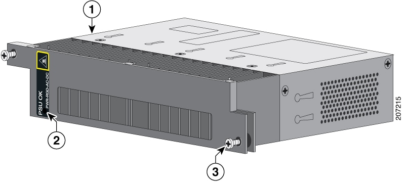
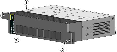
This chapter describes how to remove and install a new or replacement power supply. Your router ships with at least one installed power-supply module (AC or DC, depending on your order).
The power-supply modules are field-replaceable units (FRUs) and are hot-swappable when deployed in non-hazardous locations.


 Feedback