Cable and Connectors
10/100/1000 Ports
The 10/100/1000 Ethernet ports on the router use RJ-45 connectors. The following figure shows the pinouts.
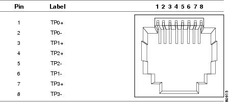
Connector pins 1, 2, 3, and 6 are used for PoE and POE+. For UPOE, all pins are used.
SFP Module Connectors
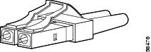
The following figure shows a LC style connector that is used with the SFP Module slots. It is a fiber-optic cable connector.
 Warning |
Statement 1051—Laser Radiation Invisible laser radiation may be emitted from disconnected fibers or connectors. Do not stare into beams or view directly with optical instruments. |
Console Port
The router has an RJ-45 (RS-232) console port.
The RJ-45 console port uses an 8-pin RJ-45 connector . An RJ-45-to-DB-9 adapter cable is used to connect the console port of the router to a console PC. You need to provide a RJ-45-to-DB-25 female DTE adapter if you want to connect the router console port to a terminal. You can order a kit (part number ACS-DSBUASYN=) containing that adapter.
Alarm Port
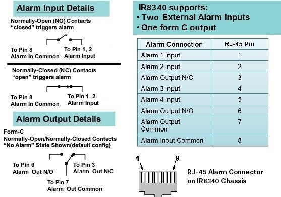
The alarm port uses an RJ-45 connector. The following figure shows the alarm port details. For more information on alarm input and output, see Alarm Ports. For information on alarm ratings, see Alarm Ratings.
Cables and Adapters
SFP Module Cables
Each port must match the wave-length specifications on each end of the cable, and for reliable communications, the cable must not exceed the allowable length.
For more information about SFP/SFP+ modules and cables, see Transceiver Modules .
Console Port Adapter Pinouts
The console port uses an 8-pin RJ-45 connector. If you did not order a console cable, you need to provide an RJ-45-to-DB-9 adapter cable to connect the router console port to a PC console port. You need to provide an RJ-45-to-DB-25 female DTE adapter if you want to connect the router console port to a terminal. You can order an adapter (part number ACS-DSBUASYN=).
The following table shows the pinout descriptions for the DB-9 connections:
|
Console Port (DTE) |
RJ-45 to RJ-45 Rollover Cable |
RJ-45 to DB-9 Terminal Adapter |
Console Device |
|
|---|---|---|---|---|
|
Signal |
RJ-45 Pin |
RJ-45 Pin |
DB-9 Pin |
Signal |
|
RTS |
11 |
8 |
8 |
CTS |
|
DTR |
2 |
7 |
6 |
DSR |
|
TxD |
3 |
6 |
2 |
RxD |
|
GND |
4 |
5 |
5 |
GND |
|
GND |
5 |
4 |
5 |
GND |
|
RxD |
6 |
3 |
3 |
TxD |
|
DSR |
7 |
2 |
4 |
DTR |
|
CTS |
8 |
1 |
7 |
RTS |
The following table shows the pinout descriptions for the DB-25 connections:
|
Console Port (DTE) 2 |
RJ-45 to RJ-45 Rollover Cable |
RJ-45 to DB-25 Terminal Adapter |
Console Device |
|
|---|---|---|---|---|
|
Signal |
RJ-45 Pin |
RJ-45 Pin |
DB-25 Pin |
Signal |
|
RTS |
13 |
8 |
5 |
CTS |
|
DTR |
2 |
7 |
6 |
DSR |
|
TxD |
3 |
6 |
3 |
RxD |
|
GND |
4 |
5 |
7 |
GND |
|
GND |
5 |
4 |
7 |
GND |
|
RxD |
6 |
3 |
2 |
TxD |
|
DSR |
7 |
2 |
20 |
DTR |
|
CTS |
8 |
1 |
4 |
RTS |
 Feedback