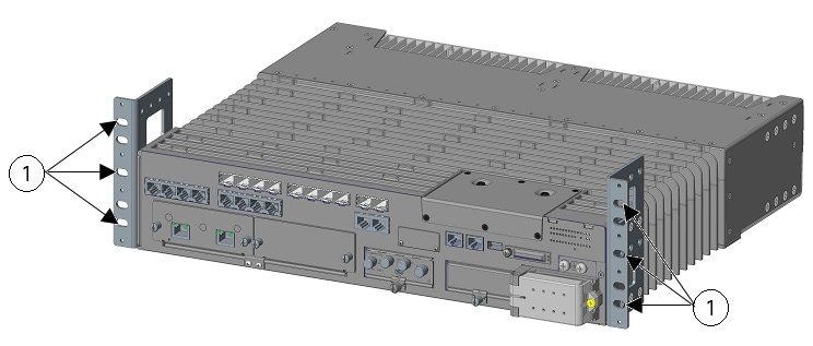
Installing and Connecting the Router
This section describes how to install and connect the Cisco IR8340 router.
 Caution |
For the optimum temperature ranges, do not operate it in an area that less than the minimum of -40°C and exceeds a maximum recommended ambient temperature of 60°C. |
 Note |
To view specifications for the Cisco Catalyst IR8340 Rugged Series Router, see the IR8340 data sheet. |


 Feedback