|
Step 1
|
configure terminal
|
Enter global configuration mode.
|
|
Step 2
|
common-pack-forwarder cert install gw
path-to-cert path-to-key
|
Install IXM gateway's certification and key (mandatory if auth-mode is
client-server):
path-to-cert – file path to the gateway’s cert
path-to-key – file path to the gateway’s key
|
|
Step 3
|
common-pack-forwarder cert install srv
path-to-cert
|
Install IXM LNS’ CA certificate (mandatory if auth-mode is other than
none):
path-to-cert – file path to the LNS’ CA cert
|
|
Step 4
|
common-pack-forwarder cert erase gw
|
Erase IXM LoRa gateway's certification and key.
|
|
Step 5
|
common-pack-forwarder cert erase srv
|
Erase LNS server's certification.
|
|
Step 6
|
common-packet-forwarder profile
|
Configure parameters for the CPF.
|
|
Step 7
|
ipaddr
ip-address port
port
|
Configure network server IP address and port.
ip-address – Network server IP address
port – Network server port number
|
|
Step 8
|
auth-mode
mode
|
Authentication mode.
-
none: use websocket (ws), default
-
client-server: authenticate both client and server with secure
websocket (wss)
-
server: server authentication, only
|
|
Step 9
|
gps enable
|
Enable CPF to utilize GPS signal.
|
|
Step 10
|
aeskey
key
|
Configure AES key used for CPF.
key – AES key used for CPF
|
|
Step 11
|
gatewayid
gateway-id
|
Configure gateway id used for CPF.
gateway-id – Gateway ID used for CPF
|
|
Step 12
|
antenna
antenna-number type
antenna-type gain
antenna-gain loss
cable-loss
|
Configure individual antenna properties.
antenna-number – Antenna ID <1,2>
antenna-type – Antenna type <omni, sector>
antenna-gain – Antenna gain
cable-loss – Cable loss
|
|
Step 13
|
region-cp
lora-region-name
|
Configure LoRa region channel plan code per naming convention defined in LoRa Alliance RP2-1.0.2 (for example: EU868, AU915,
AS923-1, AS923-2, AS923-3, IN65, RU864).
lora-region-name – LoRa region code name (optional if default one is
used)
|
|
Step 14
|
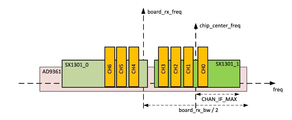
board-bw
bandwidth
|
bandwidth – Manually setup the board rx bandwidth if you need to change the default.
|
Note
|
Default board RX channel frequency and bandwidth are 866.5 MHz, 7 MHz for 800 SKU, and 908.6 MHz, 13 MHz for 900 SKU.
You need to manually configure the frequency and bandwidth for regions that use frequencies falling outside of the defaults.
AU915, KR920, and AS923-x are the specific channel plans that do not work with the default settings.
|
|
|
Step 15
|
board-freq
freq
|
freq – Manually setup the board rx frequency if you need to change the
default.
|
Note
|
Default board RX channel frequency and bandwidth are 866.5 MHz, 7 MHz for 800 SKU, and 908.6 MHz, 13 MHz for 900 SKU.
You need to manually configure the frequency and bandwidth for regions that use frequencies falling outside of the defaults.
AU915, KR920, and AS923-x are the specific channel plans that do not work with the default settings.
|
|
|
Step 16
|
tcp-user-timeout
timeout
|
Configure TCP user timeout option:
|
|
Step 17
|
tls-sni
enable
|
enable – Connect to LNS to compare the configured LNS server name with
the one embedded in the LNS server's certificate.
|
|
Step 18
|
cpf enable
|
Start the CPF.
If prompted about a Smart License, answer "yes".
|
|
Step 19
|
exit
|
Exit the CPF profile block and update the CPF configuration.
|
|
Step 20
|
exit
|
Return to privileged EXEC mode.
|
|
Step 21
|
show common-packet-forwarder info
|
(Optional) Show CPF configuration and information.
|
|
Step 22
|
show common-packet-forwarder status
|
(Optional) Show current state of CPF and if registration with NS was
successful.
|
|
Step 23
|
show common-packet-forwarder log list
|
(Optional) List available log options such as CPF configuration or trace.
|
|
Step 24
|
show common-packet-forwarder log name trace
number-of-lines
|
(Optional) Display the CPF trace log.
number-of-lines – Number of lines in log to display from end of
file.
|
|
Step 25
|
show common-packet-forwarder log name config
number-of-lines
|
(Optional) Display the current CPF configuration.
number-of-lines – Number of lines in config to display from end of
file.
|
|
Step 26
|
debug cpf
|
(Optional) Change CPF trace log level to “DEBUG”.
|
Note
|
The default log level is "WARNING". This command is to change CPF log
level to "DEBUG".
|
|

 Feedback