- Preface
- Introduction to Cisco IOS XR Software
- Bringing Up the Cisco IOS XR Software on a Standalone Router
- Bringing Up the Cisco IOS XR Software on a Multishelf System
- Configuring General Router Features
- Configuring Additional Router Features
- CLI Tips, Techniques, and Shortcuts
- Troubleshooting the Cisco IOS XR Software
- Understanding Regular Expressions, Special Characters, and Patterns
- Glossary
- Index
- Contents
- Prerequisites
- Restrictions
- Information About Bringing Up a Multishelf System
- Cabling the Control Network Using 22-Port Shelf Controller Gigabit Ethernet Cards
Bringing Up the Cisco IOS XR Software on a Multishelf System
This chapter describes how to bring up Cisco IOS XR software on a Cisco CRS Multishelf System for the first time. Layer 2 system switching is achieved using an integrated switch located on the 22-port shelf controller Gigabit Ethernet (22-port SCGE) card. The 22-port SCGE card is available as of Cisco IOS XR Software Release 3.4.1. The configuration and cabling of the Cisco CRS Multishelf System using the 22-port SCGE card is described in this chapter.
Contents
•![]() Information About Bringing Up a Multishelf System
Information About Bringing Up a Multishelf System
•![]() Cabling the Control Network Using 22-Port Shelf Controller Gigabit Ethernet Cards
Cabling the Control Network Using 22-Port Shelf Controller Gigabit Ethernet Cards
•![]() Configuring the Integrated Switches
Configuring the Integrated Switches
•![]() Bringing Up and Configuring Rack 0
Bringing Up and Configuring Rack 0
•![]() Bringing Up and Verifying FCCs
Bringing Up and Verifying FCCs
•![]() Bringing Up and Verifying the Non-DSC LCC
Bringing Up and Verifying the Non-DSC LCC
•![]() Verifying Fabric Cabling Connections
Verifying Fabric Cabling Connections
Prerequisites
The following sections describe the software and hardware requirements for bringing up a multishelf system running Cisco IOS XR Software Release 4.1.
Software Requirements
The multishelf system requires the following software:
•![]() Compatible ROM Monitor firmware on all RPs.
Compatible ROM Monitor firmware on all RPs.

If the router is brought up with an incompatible version of the ROM Monitor software, then the standby RP may fail to boot. If a boot block occurs in a multishelf system, contact your Cisco Systems support representative for assistance. See Obtaining Documentation and Submitting a Service Request.
Cisco CRS multishelf systems should be upgraded to ROMMON release 1.5.3 before being upgraded to Cisco IOS XR Release 4.1 to ensure that RPs are assigned the correct rack numbers during system boot.
•![]() On a 22-port SCGE card-based system, the minimum ROMMON version required is 1.43.
On a 22-port SCGE card-based system, the minimum ROMMON version required is 1.43.
For more information, see Cisco IOS XR ROM Monitor Guide for the Cisco CRS Router .
Hardware Requirements
Before you can bring up a multishelf system, the system components must be physically installed and tested. A variety of multishelf system configurations are supported, and they require the following components:
•![]() One, two, three, or four 16-slot line card chassis (LCCs):
One, two, three, or four 16-slot line card chassis (LCCs):
–![]() Each LCC must contain eight FC/M (S13) fabric cards.
Each LCC must contain eight FC/M (S13) fabric cards.
–![]() There can be up to 64 modular services cards (MSCs) among all LCCs.
There can be up to 64 modular services cards (MSCs) among all LCCs.
•![]() Two 22-port shelf controller gigabit ethernet (SCGE) cards for each FCC
Two 22-port shelf controller gigabit ethernet (SCGE) cards for each FCC
•![]() Single-FCC systems require one FCC; two-FCC systems require two FCCs; and four-FCC systems require four FCCs. A minimum of eight S2 switch fabric cards are required for up to three LCCs; 24 S2 cards are required for 4 LCCs. In two- and four-FCC configurations, the S2 cards are distributed equally in the FCCs.
Single-FCC systems require one FCC; two-FCC systems require two FCCs; and four-FCC systems require four FCCs. A minimum of eight S2 switch fabric cards are required for up to three LCCs; 24 S2 cards are required for 4 LCCs. In two- and four-FCC configurations, the S2 cards are distributed equally in the FCCs.
For instructions to install, cable, and verify a multishelf system, see the documents listed on the Cisco CRS documentation web page listed in the "Related Documents" section.
Restrictions
The following restrictions apply to multishelf systems installed with Cisco IOS XR Software
Release 4.1.
•![]() The multishelf system supports:
The multishelf system supports:
–![]() Up to eight 16-slot LCCs.
Up to eight 16-slot LCCs.
–![]() One, two, or four FCCs.
One, two, or four FCCs.
–![]() Two 22-port shelf controller Gigabit Ethernet (SCGE) cards for each FCC, to form a Control Ethernet plane used for administrative management and for monitoring of the system.
Two 22-port shelf controller Gigabit Ethernet (SCGE) cards for each FCC, to form a Control Ethernet plane used for administrative management and for monitoring of the system.
•![]() The 4-slot and 8-slot LCCs are not supported.
The 4-slot and 8-slot LCCs are not supported.
•![]() Although Cisco IOS XR Software Release 4.1 supports the addition of a second line card chassis, the removal of a line card chassis is restricted. Consult your Cisco Technical Support representative for more information (see the "Obtaining Documentation and Submitting a Service Request" section).
Although Cisco IOS XR Software Release 4.1 supports the addition of a second line card chassis, the removal of a line card chassis is restricted. Consult your Cisco Technical Support representative for more information (see the "Obtaining Documentation and Submitting a Service Request" section).
Information About Bringing Up a Multishelf System
The following sections provide information that is good to know before you bring up a multishelf system:
Bringup Overview
The bringup procedure for a multishelf system starts after the hardware installation is complete. The bringup procedure tasks configure the system components to work together and verify the operation and configuration of system components. To bring up the multishelf system, complete the following procedures in the sequence shown:
1. ![]() Configuring the Integrated Switches
Configuring the Integrated Switches
2. ![]() Bringing Up and Configuring Rack 0
Bringing Up and Configuring Rack 0
3. ![]() Bringing Up and Verifying FCCs
Bringing Up and Verifying FCCs
4. ![]() Bringing Up and Verifying the Non-DSC LCC
Bringing Up and Verifying the Non-DSC LCC
5. ![]() Verifying the Spanning Tree
Verifying the Spanning Tree
During the bringup procedure, you need the information presented in the following section.
Preparing a Rack Number Plan
In a multishelf system, each chassis must be assigned a unique rack number, as shown in Figure 3-1. This rack number is used to identify a chassis in the system, and maintain the software and configurations for the chassis.
Figure 3-1 DSC in a CRS-MC-FC24 Multishelf System
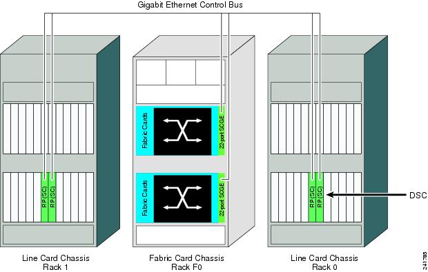

Note ![]() Chassis, shelf, and rack are used interchangeably. Each term refers to the physical tower that contains the installed cards, power, and cooling equipment. In general, chassis describes the system components. Rack is used in software to assign a rack number to each chassis.
Chassis, shelf, and rack are used interchangeably. Each term refers to the physical tower that contains the installed cards, power, and cooling equipment. In general, chassis describes the system components. Rack is used in software to assign a rack number to each chassis.
A rack number plan lists each chassis in a system with the correct chassis serial ID and an assigned rack number. The serial ID is the chassis serial number, which can be accessed by the software and uniquely identifies the chassis. The rack number for an LCC is a number in the range of 0 to 255, which is easier to remember and read than serial numbers in display messages.
The rack number plan is used during the startup and configuration of Rack 0. The LCC that hosts the DSC must be configured as Rack 0. The non-DSC LCC must be configured to use a rack number in the range of 1 to 255. FCC rack numbers range from F0 to F3, as shown in Table 3-1, Table 3-2, and Table 3-3.
Table 3-1 shows a sample rack number plan for a single-FCC system.
|
|
|
|
|---|---|---|
LCC containing the active DSC |
0 |
|
Non-DSC LCC |
1 |
|
LCC |
2 |
|
LCC |
3 |
|
Fabric chassis |
F0 |
Table 3-2 shows a sample rack number plan for a two-FCC system.
|
|
|
|
|---|---|---|
LCC containing the active DSC |
0 |
|
Non-DSC LCC |
1 |
|
LCC |
2 |
|
LCC |
3 |
|
Fabric chassis 0 |
F0 |
|
Fabric chassis 1 |
F1 |
Table 3-3 shows a sample rack number plan for a four-FCC system.
To complete the rack number plan, change the rack number for the non-DSC LCC if you want, and record the serial number for each chassis. The chassis serial number is attached to the back of the chassis, as shown in Figure 3-2 and Figure 3-3.
Figure 3-2 Location of the Serial Number on a Fabric Card Chassis

Figure 3-3 Location of the Serial Number on a Line Card Chassis

If you cannot locate or read the chassis serial number on a chassis, you can view the serial number stored in the software, as described in the following documents:
•![]() To display the chassis serial numbers in administration EXEC mode, see Cisco IOS XR System Management Configuration Guide for the Cisco CRS Router.
To display the chassis serial numbers in administration EXEC mode, see Cisco IOS XR System Management Configuration Guide for the Cisco CRS Router.
•![]() To display the configured chassis serial numbers in administration EXEC mode, see Cisco IOS XR System Management Configuration Guide for the Cisco CRS Router.
To display the configured chassis serial numbers in administration EXEC mode, see Cisco IOS XR System Management Configuration Guide for the Cisco CRS Router.
•![]() To display the chassis serial numbers in ROM Monitor, see Cisco IOS XR ROM Monitor Guide for the Cisco CRS Router.
To display the chassis serial numbers in ROM Monitor, see Cisco IOS XR ROM Monitor Guide for the Cisco CRS Router.
See the "Bringing Up and Configuring Rack 0" section for complete instructions to bring up a new router and configure the rack numbers.
Cabling the Control Network Using 22-Port Shelf Controller Gigabit Ethernet Cards
This section describes how to connect cables between two 22-port SCGE cards and the other components of a multishelf system. These connections establish control network connectivity for the multishelf system.
Control Network Cabling
This section describes cabling assignments for various multishelf system configurations. The following subsections are included:
•![]() Connections for a Single-FCC System
Connections for a Single-FCC System
•![]() Connections for a Two-FCC System
Connections for a Two-FCC System
•![]() Connections for a Four-FCC System
Connections for a Four-FCC System
The multishelf system is connected with two paths: LCC0 and LCC1. These paths have Gigabit Ethernet (GE) connections (on the RP) that are connected to one or more GE connections (on the 22-port SCGE cards) in the FCCs. The important thing about the dual paths is that all chassis are interconnected through a path through the 22-port SCGE card network controller and through the fabric. The 22-port SCGE card provides the GE path, or Control Ethernet network, among all chassis. The second path runs through the fabric cards in all LCCs and FCCs, which are interconnected with optical array cables called fabric cables.
Note the following connection tips:
•![]() Any GE ports can be used, in any sequence, but we suggest using ports in the sequence left to right as a convention to enable easier maintenance.
Any GE ports can be used, in any sequence, but we suggest using ports in the sequence left to right as a convention to enable easier maintenance.
•![]() SCGE0 is the 22-port SCGE card in the FCC upper card cage. SCGE1 is the 22-port SCGE card in the FCC lower card cage.
SCGE0 is the 22-port SCGE card in the FCC upper card cage. SCGE1 is the 22-port SCGE card in the FCC lower card cage.
Prerequisites
•![]() Before cabling the system, install each line card chassis (LCC) and fabric card chassis (FCC) in the planned location.
Before cabling the system, install each line card chassis (LCC) and fabric card chassis (FCC) in the planned location.
For information on installing the LCCs and FCCs, see the following documents:
–![]() Cisco CRS Carrier Routing System Fabric Card Chassis Installation Guide
Cisco CRS Carrier Routing System Fabric Card Chassis Installation Guide
–![]() Cisco CRS Carrier Routing System 16-Slot Line Card Chassis Installation Guide
Cisco CRS Carrier Routing System 16-Slot Line Card Chassis Installation Guide
•![]() All connections are made using single-mode LC to LC fiber cables. Determine the required amount of cabling based on the configuration in use:
All connections are made using single-mode LC to LC fiber cables. Determine the required amount of cabling based on the configuration in use:
–![]() Single-FCC system requires 9 cables—8 RP to SCGE cables and 1 mesh cable
Single-FCC system requires 9 cables—8 RP to SCGE cables and 1 mesh cable
–![]() Two-FCC system requires 14 cables—8 RP to SCGE cables and 6 mesh cables
Two-FCC system requires 14 cables—8 RP to SCGE cables and 6 mesh cables
–![]() Four-FCC system requires 36 cables—8 RP to SCGE cables and 28 mesh cables
Four-FCC system requires 36 cables—8 RP to SCGE cables and 28 mesh cables
Connections for a Single-FCC System
Figure 3-4 shows the cabling scheme for a single-FCC system. Table 3-4 lists the cabling connections that must be completed between the RPs and the 22-port SCGE cards, and Table 3-5 lists the mesh connection in a single-FCC system.
Figure 3-4 Connections Within a Single-FCC Multishelf System
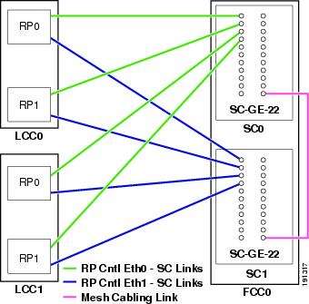
|
|
|
|
|---|---|---|
FCC0 |
SC0 |
GE21 |
SC1 |
GE21 |
Connections for a Two-FCC System
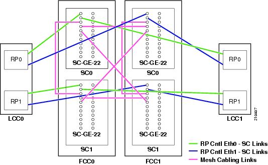
Figure 3-5 shows the cabling scheme for a two-FCC system. Table 3-6 lists the cabling connections that must be completed between the RPs and the 22-port SCGE cards and Table 3-7 lists the mesh cabling connections in a two-FCC system.
Figure 3-5 Connections Within a Two-FCC Multishelf System
Connections for a Four-FCC System
Figure 3-6 shows the cabling scheme for a four-FCC system. Table 3-8 lists the cabling connections that must be completed between the RPs and the 22-port SCGE cards. Figure 3-7 shows the mesh cabling connections in a four-FCC system.
Figure 3-6 Connections Within a Four-FCC Multishelf System
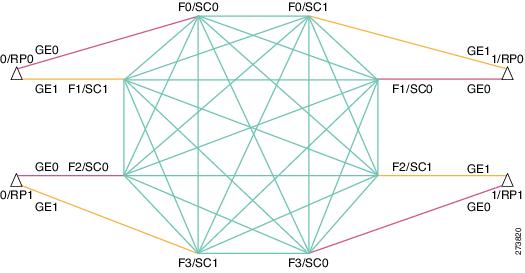
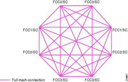
Mesh Cabling (Four-FCC System)
To complete the cabling of a four-FCC system, all the 22-port SCGE cards in the FCCs must be connected to each other in a full-mesh configuration. This provides a great amount of redundancy, so in the event that one of the nodes fails, network traffic is directed to any of the other nodes. Figure 3-7 shows a graphical view of the full-mesh configuration.
Figure 3-7 Mesh Cabling Diagram (Four-FCC System)
Configuring the Integrated Switches
Integrated switches are two Gigabit Ethernet switches placed on system controller cards in the fabric chassis. The system controller card is called a 22-port shelf controller Gigabit Ethernet (22-port SCGE) card, because it contains 22 ports on the front panel. Each 22-port SCGE card provides 22 Gigabit Ethernet (GE) links, which are used to interconnect control network connections of the different Cisco CRS chassis.
For information about the cabling schemes for a single-FCC multishelf system, two-FCC multishelf system, and four-FCC multishelf system, see Cisco CRS Carrier Routing System Multishelf System Interconnection and Cabling Guide.
This section includes the following topics:
•![]() Prerequisites for Integrated Switches
Prerequisites for Integrated Switches
•![]() Information About the Integrated Switch Implementation
Information About the Integrated Switch Implementation
•![]() Implementing the Integrated Switches on a Multishelf System
Implementing the Integrated Switches on a Multishelf System
Prerequisites for Integrated Switches
Before configuring integrated switches, be sure that the following conditions are met:
Software Requirements
•![]() Requires ROMMON 1.43 or higher on all RP and 22-port SCGE nodes. The 22-port SCGE card comes with ROMMON 1.43 or later version.
Requires ROMMON 1.43 or higher on all RP and 22-port SCGE nodes. The 22-port SCGE card comes with ROMMON 1.43 or later version.
Note ![]() ROMMON 1.43 is the first ROMMON version to support 22-port SCGE cards.
ROMMON 1.43 is the first ROMMON version to support 22-port SCGE cards.
•![]() Requires Cisco IOS XR Software Release 3.4.1 or later release to support the 22-port SCGE cards.
Requires Cisco IOS XR Software Release 3.4.1 or later release to support the 22-port SCGE cards.
Hardware Requirements
Route processors (RPs) must be revision 8 or higher. SMF cables are required and LX optics are recommended.
Before You Begin
Before you begin to bring up the integrated switch control network, consider the following items:
•![]() See Cabling the Control Network Using 22-Port Shelf Controller Gigabit Ethernet Cards for information on cabling guidelines for the 22-port SCGE cards.
See Cabling the Control Network Using 22-Port Shelf Controller Gigabit Ethernet Cards for information on cabling guidelines for the 22-port SCGE cards.
•![]() For additional information regarding Cisco IOS commands and usage, see the "Cisco IOS Software Configuration" page at the following URL:
For additional information regarding Cisco IOS commands and usage, see the "Cisco IOS Software Configuration" page at the following URL:
http://www.cisco.com/univercd/cc/td/doc/product/software/index.htm
Information About the Integrated Switch Implementation
To implement the integrated switch, you must understand the following concepts:
•![]() Integrated Switch Control Network Topology
Integrated Switch Control Network Topology
•![]() LED Definitions for the Integrated Switch System
LED Definitions for the Integrated Switch System
Integrated Switch Overview
Four switches are present on the 22-port SCGE card. Two switches provide connectivity to all cards inside the chassis. Two more Gigabit Ethernet (GE) switches on the board allow for all the external connections.
Table 3-9 lists the differences between intra-rack switch and inter-rack switch for the 22-port SCGE card.
Integrated Switch Functions
The 22-port SCGE performs the following functions:
•![]() Arbitrates for shelf ownership (active mode or standby mode) with the other 22-port SCGE card that is installed on the rack.
Arbitrates for shelf ownership (active mode or standby mode) with the other 22-port SCGE card that is installed on the rack.
•![]() Provides 22 GE ports for external system management communication across racks.
Provides 22 GE ports for external system management communication across racks.
•![]() Performs the same type of control plane functions as the current SCGE for the multishelf system.
Performs the same type of control plane functions as the current SCGE for the multishelf system.
•![]() Supports 22 GE ports and has the capability to support up to 72 line card chassis.
Supports 22 GE ports and has the capability to support up to 72 line card chassis.
•![]() Validates the link state before running the Spanning Tree Protocol (STP) that prevents a link from being unidirectional and causes a spanning tree loop.
Validates the link state before running the Spanning Tree Protocol (STP) that prevents a link from being unidirectional and causes a spanning tree loop.
•![]() Checks the link for any unidirectional mode when a cable is plugged into the 22-port SCGE. If the 22-port SCGE software detects this condition, the port cannot be allowed to participate in the spanning tree algorithm.
Checks the link for any unidirectional mode when a cable is plugged into the 22-port SCGE. If the 22-port SCGE software detects this condition, the port cannot be allowed to participate in the spanning tree algorithm.
In active mode, you can perform the following functions:
•![]() Download the Ethernet MAC addresses from the backplane EPROM and assign them to all boards in the rack.
Download the Ethernet MAC addresses from the backplane EPROM and assign them to all boards in the rack.
•![]() Start up and monitor power supplies, rack fans, and thermal sensors within the fabric rack upon request from the system management network.
Start up and monitor power supplies, rack fans, and thermal sensors within the fabric rack upon request from the system management network.
•![]() Start up board power supplies and download software images to the fabric cards in the rack upon request from the system management network. Start and reset board processors.
Start up board power supplies and download software images to the fabric cards in the rack upon request from the system management network. Start and reset board processors.
•![]() Send alarms, reset, and shut down portions of the rack hardware in case of abnormal or dangerous conditions in the rack.
Send alarms, reset, and shut down portions of the rack hardware in case of abnormal or dangerous conditions in the rack.
•![]() Keep a log of the 22-port SCGE cards and rack activity on nonvolatile memory. Take core dumps onto the hard disk.
Keep a log of the 22-port SCGE cards and rack activity on nonvolatile memory. Take core dumps onto the hard disk.
•![]() Initiate a self-reset and rearbitration for shelf ownership in case of a watchdog timeout.
Initiate a self-reset and rearbitration for shelf ownership in case of a watchdog timeout.
•![]() Control and monitor the fan speed.
Control and monitor the fan speed.
In standby mode, you can perform the following functions:
•![]() Test the FE links to all the rack hardware periodically.
Test the FE links to all the rack hardware periodically.
•![]() Keep the local state information synchronized to the rack master.
Keep the local state information synchronized to the rack master.
•![]() Rearbitrate the shelf ownership if the primary router releases ownership.
Rearbitrate the shelf ownership if the primary router releases ownership.
Integrated Switch Control Network Topology
Once the 22-port SCGE cards are installed, the control network topology ceases to be a simple hub-and-spoke set of connections.
A control network topology provides the following functions:
•![]() Each RP in a line card chassis is connected to two different 22-port SCGE cards in a fabric chassis.
Each RP in a line card chassis is connected to two different 22-port SCGE cards in a fabric chassis.
•![]() The 22-port SCGE cards are interconnected in a full mesh to provide an available control network with multiple redundant Ethernet connections.
The 22-port SCGE cards are interconnected in a full mesh to provide an available control network with multiple redundant Ethernet connections.
•![]() The 22-port SCGE cards appear to be a backbone in which different RPs are connected from the outside.
The 22-port SCGE cards appear to be a backbone in which different RPs are connected from the outside.
•![]() Both the 22-port SCGE cards and RPs run the rapid spanning tree protocol (RSTP) to provide a loop-free topology.
Both the 22-port SCGE cards and RPs run the rapid spanning tree protocol (RSTP) to provide a loop-free topology.
LED Definitions for the Integrated Switch System
The 22-port SCGE displays the LEDs on the front panel foe every port. Table 3-10 lists the LEDs that are used to obtain information about the link.
|
|
|
|---|---|
Green |
Link Up |
Blinking Green |
Activity |
Amber |
Port error disabled Unidirectional Link Detection (UDLD) |
Off |
Link Down |
Implementing the Integrated Switches on a Multishelf System
This section presents topics that explain how to implement the integrated switches:
•![]() Implementing the Integrated Switch Through ROMMON
Implementing the Integrated Switch Through ROMMON
•![]() Implementing the Integrated Switch in Cisco IOS XR
Implementing the Integrated Switch in Cisco IOS XR
•![]() Booting Up the Integrated Switch Network
Booting Up the Integrated Switch Network
Implementing the Integrated Switch Through ROMMON
When the 22-port SCGE comes out of reset, the ROM Monitor must initialize the switches so that no loops get formed and the processor can communicate with the rest of the system. The ROM Monitor configures the switches.
Table 3-11 lists the ROM Monitor switch configuration.
Implementing the Integrated Switch in Cisco IOS XR
When the RP and SCGE node boots to Cisco IOS XR software, Rapid Spanning Tree Protocol (RSTP) starts to run on that node. On the RP, the RSTP configures the state of the 2-GE and inter-RP (backplane) FE port. RSTP runs on all ports of inter-rack switches in addition to the intra-rack switch ports.
Assigning a Bridge Priority
The switches on the 22-port SCGE, which are connected to each other, form the core of the network. The RP connections form the edge (regardless of whether the 22-port SCGEs are connected in a full or partial mesh). In steady state, the integrated switch network has the root in the core. The root is one of the 22-port SCGEs.The following default priorities are achieved with the RSTP software:
•![]() RP is set to 36864.
RP is set to 36864.
•![]() 22-port SCGE is set to 32768.
22-port SCGE is set to 32768.
Booting Up the Integrated Switch Network
For the 22-port SCGEs, the switching control fabric of the control Ethernet is brought up at the same time as the Cisco CRS system. Initially, the designated system controller (DSC) comes up first, followed by the FCCs and line card chassis (LCCs).
Reenabling the Ports
Perform this task to reenable the ports if the interfaces on the 22-port SCGE card are in the err-disable state due to a UDLD failure.
SUMMARY STEPS
1. ![]() admin
admin
2. ![]() clear controller switch errdisable {port {FE | GE} {0 | 1}} {location node-id}}
clear controller switch errdisable {port {FE | GE} {0 | 1}} {location node-id}}
3. ![]() clear controller switch inter-rack {errdisable {ports {number | all} | statistics {all | ports number}} {location node-id}
clear controller switch inter-rack {errdisable {ports {number | all} | statistics {all | ports number}} {location node-id}
DETAILED STEPS
Verifying the Connections of the Integrated Switch Control Network
This section presents how to verify the connections and operations of the integrated switch control network with 22-port SCGEs:
•![]() Verifying the Control Ethernet Connection
Verifying the Control Ethernet Connection
•![]() Verifying the Port Statistics
Verifying the Port Statistics
•![]() Verifying Unidirectional Link Detection (UDLD) Protocol Information
Verifying Unidirectional Link Detection (UDLD) Protocol Information
•![]() Verifying Spanning Tree Protocol Information
Verifying Spanning Tree Protocol Information
Verifying the Control Ethernet Connection
To verify the control Ethernet connection on intra-rack switches, use the show controllers switch command with the ports and location keywords, as shown in the following example:
RP/0/RP0/CPU0:router(admin)# show controllers switch 0 ports location 0/rp0/Cpu0
Switch Instance 0:
FE Port 0 : Up, STP State : FORWARDING (Connects to - 0/RP0)
FE Port 1 : Up, STP State : FORWARDING (Connects to - 0/RP1)
FE Port 2 : Up, STP State : FORWARDING (Connects to - 0/SM0)
FE Port 3 : Up, STP State : FORWARDING (Connects to - 0/SM1)
FE Port 4 : Up, STP State : FORWARDING (Connects to - 0/SM2)
FE Port 5 : Up, STP State : FORWARDING (Connects to - 0/SM3)
FE Port 6 : Down (Connects to - )
FE Port 7 : Down (Connects to - )
FE Port 8 : Down (Connects to - 0/LC0)
FE Port 9 : Up, STP State : FORWARDING (Connects to - 0/LC1)
FE Port 10 : Down (Connects to - 0/LC2)
FE Port 11 : Down (Connects to - 0/LC3)
FE Port 12 : Up, STP State : FORWARDING (Connects to - 0/LC4)
FE Port 13 : Down (Connects to - 0/LC5)
FE Port 14 : Up, STP State : FORWARDING (Connects to - 0/LC6)
FE Port 15 : Down (Connects to - 0/LC7)
GE Port 0 : Down (Connects to - GE_0)
GE Port 1 : Down (Connects to - GE_1)
Verifying the Port Statistics
To verify the port statistics, use the show controllers switch command with the statistics and location keywords, as shown in the following example:
RP/0/RP0/CPU0:router(admin)# show controllers switch 0 statistics location 0/rp0/Cpu0
Switch Instance 0:
Port Tx Frames Tx Errors Rx Frames Rx Errors Connects
------------------------------------------------------------------------------------------
0 : 58551626 0 51173271 2 0/RP0
1 : 14529487 0 11369535 8 0/RP1
2 : 9486386 0 2822778 4 0/SM0
3 : 9486921 0 2823279 4 0/SM1
4 : 9486996 0 2823668 4 0/SM2
5 : 9486422 0 2822799 4 0/SM3
6 : 0 0 0 0
7 : 0 0 0 0
8 : 0 0 0 0 0/LC0
9 : 18044937 0 11711858 4 0/LC1
10 : 0 0 0 0 0/LC2
11 : 0 0 0 0 0/LC3
12 : 13895759 0 13753778 4 0/LC4
13 : 0 0 0 0 0/LC5
14 : 19449052 0 13103486 4 0/LC6
15 : 0 0 0 0 0/LC7
24 : 0 0 0 0 GE_0
25 : 0 0 2 2 GE_1
To verify the port statistics, use show controllers switch inter-rack statistics command with the detail and location keywords, as shown in the following example:
RP/0/RP0/CPU0:router(admin)# show controllers switch inter-rack statistics 0 detail
location f0/sc0/cpu0
GE_Port_0
Rx fragment : 0 Tx fragment : 0
Rx unicast : 1642337 Tx unicast : 379927
Rx multicast : 51619 Tx multicast : 205950
Rx broadcast : 91436 Tx broadcast : 150357
Rx FCS error : 0 Tx FCS error : 0
Rx Pause : 0 Tx Pause : 0
Rx Undersize : 0 Tx Oversize : 0
Rx FFP drop : 0 Tx CFI drop : 0
Rx Control frame : 0 Tx Cell error : 0
Tx Jabber : 0
Tx excessive collision: 0
Tx tagged vlan : 0
Tx abort : 0
Verifying Bidirectionality
To verify the bidirection for the integrated switch, you can use the Unidirectional Link Detection (UDLD) protocol to detect unidirectional links on Ethernet ports. UDLD is a Layer 2 protocol. UDLD is useful at linkup time. If the link is detected to be unidirectional, the port is shut down. In addition, UDLD detects unidirectional failures after a port has been up and bidirectional for a certain time. If a transceiver goes wrong, UDLD protects the control network from faulty transceivers that are plugged into the control network.
To provide the port information that is disabled (UDLD), use the show controllers switch udld ports command.
Verifying Unidirectional Link Detection (UDLD) Protocol Information
To verify Unidirectional Link Detection (UDLD) protocol information for inter-rack switches, use the show controllers switch inter-rack udld location command, as shown in the following example:
RP/0/RP0/CPU0:router(admin)# show controllers switch inter-rack udld all location
f0/sc0/cpu0
Interface Gig port# 13
---
...
Current bidirectional state: Bidirectional
Current operational state: Advertisement - Single neighbor detected
...
...
Entry 1
---
...
Device name: 0_RP0_CPU0_Switch
Port ID: GE_Port_0
Neighbor echo 1 device: nodeF0_SC0_CPU0
Neighbor echo 1 port: Gig port# 13
Verifying Spanning Tree Protocol Information
To verify Spanning Tree Protocol (STP) information for intra-rack switches, use the show controllers switch stp location command, as shown in the following example:
RP/0/RP0/CPU0:router(admin)# show controllers switch stp location f0/sc0/CPU0
##### MST 0 vlans mapped: 2-4094
Bridge address 0800.453e.469a priority 36864 (36864 sysid 0)
Root address 5246.48f0.20ff priority 32768 (32768 sysid 0)
port GE_Port_0 path cost 0
Regional Root address 5246.48f0.20ff priority 32768 (32768 sysid 0)
internal cost 20000 rem hops 3
Operational hello time 1, forward delay 6, max age 8, txholdcount 6
Configured hello time 1, forward delay 6, max age 8, max hops 4
Interface Role Sts Cost Prio.Nbr Type
---------------- ---- --- --------- -------- ---------------------------
##### MST 1 vlans mapped: 1
Bridge address 0800.453e.469a priority 36865 (36864 sysid 1)
Root address 5246.48f0.20ff priority 32769 (32768 sysid 1)
port GE_Port_0 cost 20000 rem hops 3
Interface Role Sts Cost Prio.Nbr Type
---------------- ---- --- --------- -------- ----------------------------
FE_Port_1 Desg FWD 200000 128. 2 P2p
GE_Port_0 Root FWD 20000 128. 49 P2p
To verify STP information for inter-rack switches, use the show controllers switch inter-rack ports command, as shown in the following example:
RP/0/RP0/CPU0:router(admin)# show controllers switch inter-rack stp location f0/sc0/cpu0
##### MST 0 vlans mapped: 2-4094
Bridge address 5246.48f0.20ff priority 32768 (32768 sysid 0)
Root this switch for the CIST
Operational hello time 1, forward delay 6, max age 8, txholdcount 6
Configured hello time 1, forward delay 6, max age 8, max hops 4
Interface Role Sts Cost Prio.Nbr Type
---------------- ---- --- --------- -------- ---------------------------
##### MST 1 vlans mapped: 1
Bridge address 5246.48f0.20ff priority 32769 (32768 sysid 1)
Root this switch for MST1
Interface Role Sts Cost Prio.Nbr Type
---------------- ---- --- --------- -------- ---------------------------
GE_13 Desg FWD 20000 128. 14 P2p
GE_14 Desg FWD 20000 128. 15 P2p
GE_15 Desg FWD 20000 128. 16 P2p
GE_17 Desg FWD 20000 128. 18 P2p
GE_22 Desg FWD 20000 128. 23 P2p
Bringing Up and Configuring Rack 0
When the control network has been established by installing, cabling, and configuring the 22-port SCGE cards, bring up and configure Rack 0 in the multishelf system, as described in the following procedure:
SUMMARY STEPS
1. ![]() Power down all LCCs and FCCs.
Power down all LCCs and FCCs.
2. ![]() Apply power to the LCC that contains the DSC.
Apply power to the LCC that contains the DSC.
3. ![]() Connect to the DSC console port and log in.
Connect to the DSC console port and log in.
4. ![]() admin
admin
5. ![]() configure
configure
6. ![]() dsc serial serial ID rack 0
dsc serial serial ID rack 0
7. ![]() dsc serial serial ID rack rackNumber
dsc serial serial ID rack rackNumber
8. ![]() dsc serial serial ID rack Fn
dsc serial serial ID rack Fn
9. ![]() commit
commit
10. ![]() show running-config | include dsc
show running-config | include dsc
11. ![]() controllers fabric plane planeNumber
controllers fabric plane planeNumber
oim count 1
oim instance 0 location Frack/slot/FM
12. ![]() commit
commit
13. ![]() end
end
DETAILED STEPS
|
|
|
|
|---|---|---|
Step 1 |
Power down all LCCs and FCCs. |
Prepares the LCCs and FCCs for startup in the proper sequence. • |
Step 2 |
Apply power to the LCC that contains the DSC. |
Boots the LCC containing the DSC. • • • |
Step 3 |
Connect to the DSC console port and log in. |
Establishes a CLI management session with the router. For more information, see the "Connecting to the Router Through the Console Port" section. |
Step 4 |
admin Example: RP/0/RP0/CPU0:router# admin |
Places the router in administration EXEC mode. |
Step 5 |
configure Example: RP/0/RP0/CPU0:router(admin)# configure |
Places the router in administration configuration mode. |
Step 6 |
dsc serial serial ID rack 0 Example: RP/0/RP0/CPU0:router(admin-config)# dsc serial TBA00000001 rack 0 |
Defines which LCC is Rack 0. • • • |
Step 7 |
dsc serial serial ID rack rackNumber Example: RP/0/RP0/CPU0:router(admin-config)# dsc serial TBA00000002 rack 1 |
Defines the rack number for the second LCC. • • • • |
Step 8 |
dsc serial serial ID rack Fn RP/0/RP0/CPU0:router(admin-config)# dsc serial TBA00000003 rack F0 |
Defines the rack number for an FCC. • • • • • |
Step 9 |
commit RP/0/RP0/CPU0:router(admin-config)# commit |
Commits the target configuration to the router running configuration. |
Step 10 |
show running-config | include dsc RP/0/RP0/CPU0:router(admin-config)# show running-config | include dsc |
Displays the committed rack number configuration. Verify that the serial numbers entered for each chassis are correct. |
Step 11 |
controllers fabric plane planeNumber oim count 1 oim instance 0 location Frack/SMslot/FM RP/0/RP0/CPU0:router(admin-config)# controllers fabric plane 0 RP/0/RP0/CPU0:router(admin-config)# oim count 1 RP/0/RP0/CPU0:router(admin-config)# oim instance 0 location F0/SM9/FM
|
Configures a plane to operate in an FCC slot. • • • • • |
Step 12 |
commit RP/0/RP0/CPU0:router(admin-config)# commit |
Commits the target configuration to the router running configuration. |
Step 13 |
end RP/0/RP0/CPU0:router(admin-config)# end RP/0/RP0/CPU0:router(admin)# |
Exits administration configuration mode and enters administration EXEC mode. |
Examples
The following examples illustrate how to bring up and configure Rack 0:
•![]() Configuring and Verifying the Rack Numbers in a Single-FCC Multishelf System: Example
Configuring and Verifying the Rack Numbers in a Single-FCC Multishelf System: Example
•![]() Mapping Each Fabric Plane in a Single-FCC Multishelf System: Example
Mapping Each Fabric Plane in a Single-FCC Multishelf System: Example
•![]() Mapping Each Fabric Plane in a Two-FCC Multishelf System: Example
Mapping Each Fabric Plane in a Two-FCC Multishelf System: Example
•![]() Mapping Each Fabric Plane in a Four-FCC Multishelf System: Example
Mapping Each Fabric Plane in a Four-FCC Multishelf System: Example
Configuring and Verifying the Rack Numbers in a Single-FCC Multishelf System: Example
In the following example, rack numbers are assigned to each LCC and FCC in administration configuration mode:
RP/0/RP0/CPU0:router# admin
RP/0/RP0/CPU0:router(admin)# configure
RP/0/RP0/CPU0:router(admin-config)# dsc serial TBA00000001 rack 0
RP/0/RP0/CPU0:router(admin-config)# dsc serial TBA00000002 rack 1
RP/0/RP0/CPU0:router(admin-config)# dsc serial TBA00000003 rack F0
RP/0/RP0/CPU0:router(admin-config)# commit
RP/0/RP0/CPU0:router(admin-config)# show running-config | include dsc
Building configuration...
dsc serial TBA00000003 rack F0
dsc serial TBA00000001 rack 0
dsc serial TBA00000002 rack 1
RP/0/RP0/CPU0:router(admin-config)#
Mapping Each Fabric Plane in a Single-FCC Multishelf System: Example
In the following example, each fabric plane is assigned to an FCC slot in administration configuration mode:
RP/0/RP0/CPU0:router(admin-config)#
controllers fabric plane 0
RP/0/RP0/CPU0:router(admin-config)# oim count
1
RP/0/RP0/CPU0:router(admin-config)# oim
instance 0 location F0/SM9/FM
RP/0/RP0/CPU0:router(admin-config)# controllers fabric plane 1
RP/0/RP0/CPU0:router(admin-config)# oim count 1
RP/0/RP0/CPU0:router(admin-config)# oim instance 0 location F0/SM6/FM
RP/0/RP0/CPU0:router(admin-config)# controllers fabric plane 2
RP/0/RP0/CPU0:router(admin-config)# oim count 1
RP/0/RP0/CPU0:router(admin-config)# oim instance 0 location F0/SM3/FM
RP/0/RP0/CPU0:router(admin-config)# controllers fabric plane 3
RP/0/RP0/CPU0:router(admin-config)# oim count 1
RP/0/RP0/CPU0:router(admin-config)# oim instance 0 location F0/SM0/FM
RP/0/RP0/CPU0:router(admin-config)# controllers fabric plane 4
RP/0/RP0/CPU0:router(admin-config)# oim count 1
RP/0/RP0/CPU0:router(admin-config)# oim instance 0 location F0/SM12/FM
RP/0/RP0/CPU0:router(admin-config)# controllers fabric plane 5
RP/0/RP0/CPU0:router(admin-config)# oim count 1
RP/0/RP0/CPU0:router(admin-config)# oim instance 0 location F0/SM15/FM
RP/0/RP0/CPU0:router(admin-config)# controllers fabric plane 6
RP/0/RP0/CPU0:router(admin-config)# oim count 1
RP/0/RP0/CPU0:router(admin-config)# oim instance 0 location F0/SM18/FM
RP/0/RP0/CPU0:router(admin-config)# controllers fabric plane 7
RP/0/RP0/CPU0:router(admin-config)# oim count 1
RP/0/RP0/CPU0:router(admin-config)# oim instance 0 location F0/SM21/FM
RP/0/RP0/CPU0:router(admin-config)# commit
RP/0/RP0/CPU0:router(admin-config)# end
RP/0/RP0/CPU0:router(admin)#
Mapping Each Fabric Plane in a Two-FCC Multishelf System: Example
The following display is an example of a configuration for a two-FCC multishelf system:
RP/0/RP0/CPU0:router(admin)# show running-config
Building configuration...
username admin
secret 5 $1$iGx3$0BI/8hOKRUMqtfWC4IUn50
group root-system
group cisco-support
!
dsc serial TBA09250241 rack 1
dsc serial TBA09270100 rack F0
dsc serial TBA09300128 rack F1
controllers fabric plane 0
oim count 1
oim instance 0 location F0/SM0/FM
!
controllers fabric plane 1
oim count 1
oim instance 0 location F0/SM9/FM
!
controllers fabric plane 2
oim count 1
oim instance 0 location F0/SM12/FM
!
controllers fabric plane 3
oim count 1
oim instance 0 location F0/SM21/FM
!
controllers fabric plane 4
oim count 1
oim instance 0 location F1/SM0/FM
!
controllers fabric plane 5
oim count 1
oim instance 0 location F1/SM91/FM
!
controllers fabric plane 6
oim count 1
oim instance 0 location F1/SM12/FM
!
controllers fabric plane 7
oim count 1
oim instance 0 location F1/SM21/FM
!
end
Mapping Each Fabric Plane in a Four-FCC Multishelf System: Example
The following configuration display is an example of a configuration for a four-FCC multishelf system:
RP/0/RP0/CPU0:router(admin)# show running-config
Building configuration...
username admin
secret 5 $1$iGx3$0BI/8hOKRUMqtfWC4IUn50
group root-system
group cisco-support
!
dsc serial TBA09250241 rack 1
dsc serial TBA09270100 rack F0
dsc serial TBA09300128 rack F1
dsc serial TBA09460027 rack F3
dsc serial TBA09460028 rack F2
controllers fabric plane 0
oim count 1
oim instance 0 location F0/SM0/FM
!
controllers fabric plane 1
oim count 1
oim instance 0 location F0/SM9/FM
!
controllers fabric plane 2
oim count 1
oim instance 0 location F1/SM0/FM
!
controllers fabric plane 3
oim count 1
oim instance 0 location F1/SM9/FM
!
controllers fabric plane 4
oim count 1
oim instance 0 location F2/SM0/FM
!
controllers fabric plane 5
oim count 1
oim instance 0 location F2/SM9/FM
!
controllers fabric plane 6
oim count 1
oim instance 0 location F3/SM0/FM
!
controllers fabric plane 7
oim count 1
oim instance 0 location F3/SM9/FM
!
end
Bringing Up and Verifying FCCs
When Rack 0 is up and configured to support the rack number and FCC fabric plane plans, it is time to bring up and configure the FCC in the multishelf system as described in the following procedure.
SUMMARY STEPS
1. ![]() Apply power to all FCCs.
Apply power to all FCCs.
2. ![]() show controllers fabric rack all detail
show controllers fabric rack all detail
3. ![]() show controllers fabric plane all detail
show controllers fabric plane all detail
4. ![]() show controllers fabric connectivity all detail
show controllers fabric connectivity all detail
5. ![]() Verify that the links are not unidirectional
Verify that the links are not unidirectional
DETAILED STEPS
Examples
In the following examples, the fabric planes are examined in administration EXEC mode to ensure that they are ready to handle traffic.
•![]() show controllers fabric rack all detail: Example
show controllers fabric rack all detail: Example
•![]() show controllers fabric plane all detail: Example
show controllers fabric plane all detail: Example
•![]() show controllers fabric connectivity all detail: Example
show controllers fabric connectivity all detail: Example
show controllers fabric rack all detail: Example
In the following example, the rack status is normal and the server status is present:
RP/0/RP0/CPU0:router(admin)# show controllers fabric rack all detail
Rack Rack Server
Num Status Status
---- ------ ------
0 NORMAL PRESENT
1 NORMAL PRESENT
F0 NORMAL PRESENT
RP/0/RP0/CPU0:router(admin)#
show controllers fabric plane all detail: Example
In the following example, all eight planes are displayed, and the administrative and operational state of each plane is up:
RP/0/RP0/CPU0:router(admin)# show controllers fabric plane all detail
Flags: P - plane admin down, p - plane oper down
C - card admin down, c - card oper down
L - link port admin down, l - linkport oper down
A - asic admin down, a - asic oper down
B - bundle port admin Down, b - bundle port oper down
I - bundle admin down, i - bundle oper down
N - node admin down, n - node down
o - other end of link down d - data down
f - failed component downstream
m - plane multicast down, s - link port permanently shutdown
t - no barrier input
Plane Admin Oper Down Total Down
Id State State Flags Bundles Bundles
------------------------------------------------------
0 UP UP 9 3
1 UP UP 9 3
2 UP UP 9 3
3 UP UP 9 3
4 UP UP 9 3
5 UP UP 9 3
6 UP UP 9 3
7 UP UP 9 3
show controllers fabric connectivity all detail: Example
The expected output should contain a series of 1s for each of the fabric planes active in the system. If a fabric plane is administratively shut down, the output of the command remains the same. If the fabric card is physically removed or powered down, the 1 changes to a dot (.).
RP/0/RP0/CPU0:router(admin)# show controllers fabric connectivity all detail
Flags: P - plane admin down, p - plane oper down
C - card admin down, c - card oper down
L - link port admin down, l - linkport oper down
A - asic admin down, a - asic oper down
B - bundle port admin Down, b - bundle port oper down
I - bundle admin down, i - bundle oper down
N - node admin down, n - node down
o - other end of link down d - data down
f - failed component downstream
m - plane multicast down
Card In Tx Planes Rx Planes Monitored Total Percent
R/S/M Use 01234567 01234567 For (s) Uptime (s) Uptime
-------------------------------------------------------------------------------
0/1/CPU0 1 11111111 11111111 1245608 1245608 100.0000
0/6/CPU0 1 11111111 11111111 1245608 1245608 100.0000
0/RP0/CPU0 1 11111111 11111111 1245608 1245608 100.0000
0/RP1/CPU0 1 11111111 11111111 1245608 1245608 100.0000
Bringing Up and Verifying the Non-DSC LCC
When all FCCs are up and properly supporting Rack 0, it is time to bring up and configure the next LCC in the multishelf system as described in the following procedure:
SUMMARY STEPS
1. ![]() Apply power to the second LCC.
Apply power to the second LCC.
2. ![]() show controllers fabric rack all detail
show controllers fabric rack all detail
3. ![]() show controllers fabric plane all detail
show controllers fabric plane all detail
4. ![]() show controllers fabric connectivity all detail
show controllers fabric connectivity all detail
5. ![]() Verify that the links are not unidirectional.
Verify that the links are not unidirectional.
6. ![]() exit
exit
DETAILED STEPS
Verifying the Spanning Tree
When both LCCs and all FCCs are up and running, it is time to verify the spanning tree on the control network as described in the following procedure.
SUMMARY STEPS
1. ![]() admin
admin
2. ![]() show platform
show platform
3. ![]() show spantree mst 1 detail location rack/slot/cpu0
show spantree mst 1 detail location rack/slot/cpu0
DETAILED STEPS
Examples
The following examples illustrate how to verify the spanning tree:
•![]() Verify That the FCCs and Non-DSC LCC Are Communicating with the DSC: Example
Verify That the FCCs and Non-DSC LCC Are Communicating with the DSC: Example
•![]() Verify the Spanning Tree: Example
Verify the Spanning Tree: Example
Verify That the FCCs and Non-DSC LCC Are Communicating with the DSC: Example
In the following EXEC mode example, all modules are displayed and the state for all modules is "IOS XR RUN."
RP/0/RP0/CPU0:router# admin
RP/0/RP0/CPU0:router(admin)# show platform
Node Type PLIM State Config State
-----------------------------------------------------------------------------
0/3/SP MSC(SP) N/A IOS XR RUN PWR,NSHUT,MON
0/3/CPU0 MSC 16OC48-POS/DPT IOS XR RUN PWR,NSHUT,MON
0/RP0/CPU0 RP(Active) N/A IOS XR RUN PWR,NSHUT,MON
0/RP1/CPU0 RP(Standby) N/A IOS XR RUN PWR,NSHUT,MON
0/FC0/SP LCC-FAN-CT(SP) N/A IOS XR RUN PWR,NSHUT,MON
0/FC1/SP LCC-FAN-CT(SP) N/A IOS XR RUN PWR,NSHUT,MON
0/AM0/SP ALARM(SP) N/A IOS XR RUN PWR,NSHUT,MON
0/AM1/SP ALARM(SP) N/A IOS XR RUN PWR,NSHUT,MON
0/SM0/SP FC/M(SP) N/A IOS XR RUN PWR,NSHUT,MON
0/SM1/SP FC/M(SP) N/A IOS XR RUN PWR,NSHUT,MON
0/SM2/SP FC/M(SP) N/A IOS XR RUN PWR,NSHUT,MON
0/SM3/SP FC/M(SP) N/A IOS XR RUN PWR,NSHUT,MON
0/SM4/SP FC/M(SP) N/A IOS XR RUN PWR,NSHUT,MON
0/SM5/SP FC/M(SP) N/A IOS XR RUN PWR,NSHUT,MON
0/SM6/SP FC/M(SP) N/A IOS XR RUN PWR,NSHUT,MON
0/SM7/SP FC/M(SP) N/A IOS XR RUN PWR,NSHUT,MON
1/3/SP MSC(SP) N/A IOS XR RUN PWR,NSHUT,MON
1/3/CPU0 MSC 8-10GbE IOS XR RUN PWR,NSHUT,MON
1/RP0/CPU0 RP(Active) N/A IOS XR RUN PWR,NSHUT,MON
1/FC0/SP LCC-FAN-CT(SP) N/A IOS XR RUN PWR,NSHUT,MON
1/FC1/SP LCC-FAN-CT(SP) N/A IOS XR RUN PWR,NSHUT,MON
1/AM0/SP ALARM(SP) N/A IOS XR RUN PWR,NSHUT,MON
1/AM1/SP ALARM(SP) N/A IOS XR RUN PWR,NSHUT,MON
1/SM0/SP FC/M(SP) N/A IOS XR RUN PWR,NSHUT,MON
1/SM1/SP FC/M(SP) N/A IOS XR RUN PWR,NSHUT,MON
1/SM2/SP FC/M(SP) N/A IOS XR RUN PWR,NSHUT,MON
1/SM3/SP FC/M(SP) N/A IOS XR RUN PWR,NSHUT,MON
1/SM4/SP FC/M(SP) N/A IOS XR RUN PWR,NSHUT,MON
1/SM5/SP FC/M(SP) N/A IOS XR RUN PWR,NSHUT,MON
1/SM6/SP FC/M(SP) N/A IOS XR RUN PWR,NSHUT,MON
1/SM7/SP FC/M(SP) N/A IOS XR RUN PWR,NSHUT,MON
F0/SM0/SP FCC-SFC(SP) FCC-FM-1S IOS XR RUN PWR,NSHUT,MON
F0/SM3/SP FCC-SFC(SP) FCC-FM-1S IOS XR RUN PWR,NSHUT,MON
F0/SM6/SP FCC-SFC(SP) FCC-FM-1S IOS XR RUN PWR,NSHUT,MON
F0/SM9/SP FCC-SFC(SP) FCC-FM-1S IOS XR RUN PWR,NSHUT,MON
F0/SM12/SP FCC-SFC(SP) FCC-FM-1S IOS XR RUN PWR,NSHUT,MON
F0/SM15/SP FCC-SFC(SP) FCC-FM-1S IOS XR RUN PWR,NSHUT,MON
F0/SM18/SP FCC-SFC(SP) FCC-FM-1S IOS XR RUN PWR,NSHUT,MON
F0/SM21/SP FCC-SFC(SP) FCC-FM-1S IOS XR RUN PWR,NSHUT,MON
F0/SC0/CPU0 FCC-SC(Active) N/A IOS XR RUN PWR,NSHUT,MON
F0/SC1/CPU0 FCC-SC(Standby) N/A PRESENT PWR,NSHUT,MON
F0/AM1/SP ALARM(SP) N/A IOS XR RUN PWR,NSHUT,MON
RP/0/RP0/CPU0:router(admin)# end
Verify the Spanning Tree: Example
For each RP and SCGE card in the system, verify that:
•![]() One GE port in the Switched Interface column is in the forwarding (FWD) state.
One GE port in the Switched Interface column is in the forwarding (FWD) state.
•![]() Each RP and SCGE card displays the same designated root MAC address.
Each RP and SCGE card displays the same designated root MAC address.
•![]() The designated root address matches the expected SCGE card. The root address should be the switch with the lowest priority number (0).
The designated root address matches the expected SCGE card. The root address should be the switch with the lowest priority number (0).
The following EXEC commands display RP and SCGE card information that you can use to verify the spanning tree:
RP/0/RP0/CPU0:router(admin)# show spantree mst 1 detail location 0/rp0/cpu0
Instance 1
Vlans mapped: 1
Designated Root 00-0e-39-fe-70-00
Designated Root Priority 1 (0 + 1)
Designated Root Port GE_Port_0
Bridge ID MAC ADDR 00-05-9a-3e-89-4f
Bridge ID Priority 32769 (32768 + 1)
Bridge Max Age 8 sec Hello Time 1 sec Forward Delay 6 sec Max Hops 4
Switched Interface State Role Cost Prio Type
-------------------- ----- ---- --------- ---- --------------------------------
FE_Port_1 BLK altn 200000 128 P2P
GE_Port_0 FWD root 20000 128 P2P
GE_Port_1 BLK altn 20000 128 P2P
RP/0/RP0/CPU0:router(admin)# show spantree mst 1 detail location 0/rp1/cpu0
Instance 1
Vlans mapped: 1
Designated Root 00-0e-39-fe-70-00
Designated Root Priority 1 (0 + 1)
Designated Root Port GE_Port_0
Bridge ID MAC ADDR 00-05-9a-39-91-14
Bridge ID Priority 32769 (32768 + 1)
Bridge Max Age 8 sec Hello Time 1 sec Forward Delay 6 sec Max Hops 4
Switched Interface State Role Cost Prio Type
-------------------- ----- ---- --------- ---- --------------------------------
FE_Port_0 FWD desg 200000 128 P2P
GE_Port_0 FWD root 20000 128 P2P
GE_Port_1 BLK altn 20000 128 P2P
RP/0/RP0/CPU0:router(admin)# show spantree mst 1 detail location 1/rp0/cpu0
Instance 1
Vlans mapped: 1
Designated Root 00-0e-39-fe-70-00
Designated Root Priority 1 (0 + 1)
Designated Root Port GE_Port_0
Bridge ID MAC ADDR 00-05-9a-3e-89-2a
Bridge ID Priority 32769 (32768 + 1)
Bridge Max Age 8 sec Hello Time 1 sec Forward Delay 6 sec Max Hops 4
Switched Interface State Role Cost Prio Type
-------------------- ----- ---- --------- ---- --------------------------------
FE_Port_1 FWD desg 200000 128 P2P
GE_Port_0 FWD root 20000 128 P2P
GE_Port_1 BLK altn 20000 128 P2P
RP/0/RP0/CPU0:router(admin)# show spantree mst 1 detail location 1/rp1/cpu0
Instance 1
Vlans mapped: 1
Designated Root 00-0e-39-fe-70-00
Designated Root Priority 1 (0 + 1)
Designated Root Port GE_Port_0
Bridge ID MAC ADDR 00-05-9a-3e-89-fe
Bridge ID Priority 32769 (32768 + 1)
Bridge Max Age 8 sec Hello Time 1 sec Forward Delay 6 sec Max Hops 4
Switched Interface State Role Cost Prio Type
-------------------- ----- ---- --------- ---- --------------------------------
FE_Port_0 BLK altn 200000 128 P2P
GE_Port_0 FWD root 20000 128 P2P
GE_Port_1 BLK altn 20000 128 P2P
RP/0/RP0/CPU0:router(admin)# show spantree mst 1 detail location F0/SC0/cpu0
Instance 1
Vlans mapped: 1
Designated Root 00-0e-39-fe-70-00
Designated Root Priority 1 (0 + 1)
Designated Root Port GE_Port_1
Bridge ID MAC ADDR 00-05-9a-39-91-be
Bridge ID Priority 32769 (32768 + 1)
Bridge Max Age 8 sec Hello Time 1 sec Forward Delay 6 sec Max Hops 4
Switched Interface State Role Cost Prio Type
-------------------- ----- ---- --------- ---- --------------------------------
FE_Port_1 BLK altn 200000 128 P2P
GE_Port_0 BLK altn 20000 128 P2P
GE_Port_1 FWD root 20000 128 P2P
RP/0/RP0/CPU0:router(admin)# show spantree mst 1 detail location F0/SC1/cpu0
Instance 1
Vlans mapped: 1
Designated Root 00-0e-39-fe-70-00
Designated Root Priority 1 (0 + 1)
Designated Root Port GE_Port_1
Bridge ID MAC ADDR 00-05-9a-39-91-68
Bridge ID Priority 32769 (32768 + 1)
Bridge Max Age 8 sec Hello Time 1 sec Forward Delay 6 sec Max Hops 4
Switched Interface State Role Cost Prio Type
-------------------- ----- ---- --------- ---- --------------------------------
FE_Port_0 FWD desg 200000 128 P2P
GE_Port_0 BLK altn 20000 128 P2P
GE_Port_1 FWD root 20000 128 P2P
Verifying Fabric Cabling Connections
When the fabric cabling is complete and the power is on for all LCCs and FCCs, you can verify the fabric cabling connections, as described in this section.
Figure 3-8 shows the faceplate of the CRS-FCC- LED panel. The CRS-FCC-LED is also called an optical interface module (OIM) LED panel. This panel goes into slot LM0 or LM1 in a fabric card chassis.The OIM LED panel provides connectivity information on how the fabric chassis cards are functioning in the multishelf system. LEDs 0 through 11 correspond to OIM 0 through OIM 11 (FM 0 through FM 11 in software). Table 3-12 describes the possible states of the LEDs shown in Figure 3-8.
Figure 3-8 Optical Interface Module LED Panel (Part CRS-FCC-LED)
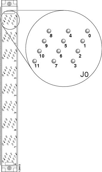
Because the OIM LED panel is present only in the fabric card chassis, the LEDs indicate the status of the bundles in the fabric card chassis only. Therefore, if a connection is wrong, the equipment assumes that the connection at the line card chassis is fixed, and the connection at the fabric card chassis is the one that needs to be relocated to the correct position as indicated by the LEDs.
Bundles are mapped to LEDs as follows:
The OIM LED panel has 9 rows of 12 LEDs— the 9 rows correspond to the 9 connectors for each slot, and 12 LEDs correspond to the 12 slots in the cage. Separate OIM LED panels provide status for the upper and lower card cages. The LED rows map to the connector number, and the LEDs in each LED row map to the slot number.
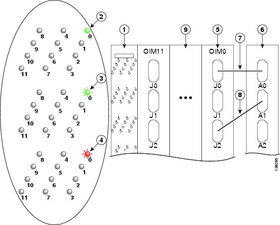
The following description explains the states of LEDs on the OIM LED panel. In Figure 3-9, fabric cables should connect an LCC S13 card to the FCC S2 card as follows: A0 to J0, A1 to J1, and A2 to J2. Instead, A1 is incorrectly connected to J2. This incorrect connection causes the LED corresponding to J2 to blink red, indicating that the cable connection is incorrect. The LED corresponding to J1 blinks green to show where the misplaced cable should be connected.
Figure 3-9 Illustration of How OIM LED Panel LEDs Map to Bundles and Slots (Single-Module Cabling)
Where to Go Next
For information on configuring basic router features, see Chapter 4 "Configuring General Router Features."
 Feedback