Internal modules
To access the internal modules on the device, you must first remove the chassis cover. For instructions on how to remove and replace the chassis cover on the device, see the sections on Precautions.
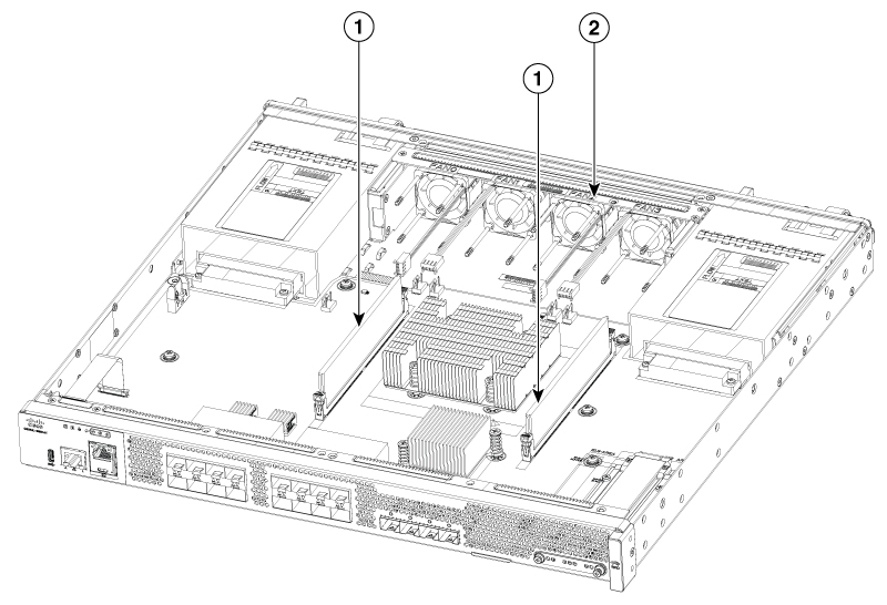
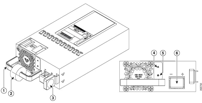
| Number | Description |
|---|---|
|
1 |
DIMMs |
|
2 |
Fan tray |
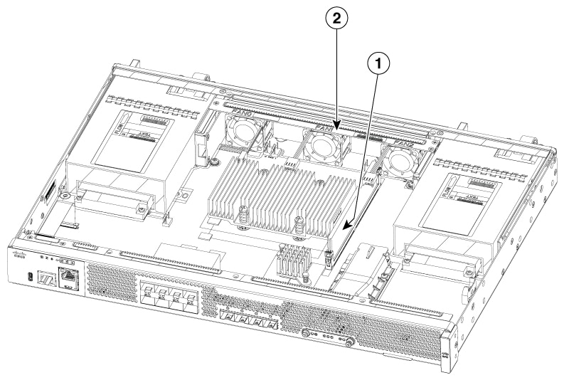
| Number | Description |
|---|---|
|
1 |
DIMM |
|
2 |
Fan tray |
Precautions
Before removing the cover, note these details:
-
Do not run the router with the cover off. Doing so can cause the router to overheat.
-
Disconnect all power cables.
-
Remove the device from the rack
-
Use a number-2 Phillips screwdriver to perform the following tasks.
Remove the chassis cover
To remove the cover, perform these steps:
Procedure
|
Step 1 |
Read the Safety Warnings and disconnect the power supply before you perform any module replacement. |
|
Step 2 |
Confirm the device is turned off and disconnected from the power supply or power supplies. If a redundant power is used, disconnect from the redundant power supply. |
|
Step 3 |
Place the chassis on a flat surface. |
|
Step 4 |
Remove the top and side cover screws. |
|
Step 5 |
Lift the cover straight up. |
Replace the cover
To replace the cover, perform these steps:
Procedure
|
Step 1 |
Place the chassis on a flat surface. |
||||||
|
Step 2 |
Drop the cover straight down and ensure that the side flanges insert into the chassis. Care should be taken to not damage the EMC Gaskets.
|
||||||
|
Step 3 |
Install the top and side cover screws. 
|


 Feedback