Cisco 8400 Series Secure Routers

The Cisco 8400 Series Secure Routers are optimized for campus edge deployments. These routers are powered by a secure networking processor to accelerate encryption and threat protection throughput.

This document covers hardware installation-specific details only for the following routers:

  • C8475-G2

  • C8455-G2

For more information on the features and specifications, refer to the Cisco 8400 Series Secure Routers datasheet.

Features

This section describes the hardware features of the Cisco C8400 Series Secure Routers.

Table 1. Different features of Cisco C8400 Series Secure Routers

Feature

C8455-G2

C8475-G2

Ethernet Ports

8x 1GE SFP

2x 10GE SFP+

2x 25GE SFP28

8x 1GE SFP

8x 10GE SFP+

4x 25GE SFP28

Rack Unit

1RU

1RU

System Memory (DRAM) 32GB DRAM (16GB on-board memory + 16GB UDIMM) Default: 32GB DRAM (2x 16GB UDIMMs) Upgrade option: 64GB DRAM (2x 32GB UDIMMs)

Storage

Default: 32GB M.2 USB Upgrade Options: 600GB, 2TB M.2 SSD

Default: 32GB M.2 USB Upgrade Options: 600GB, 2TB M.2 SSD

Boot Flash Storage

32GB

32GB

Management Interface

1x RJ45

10/100/1000 Mbps

1x RJ45

10/100/1000 Mbps

ConsolePort

1x RJ45

1x USB Micro-USB (Type B)

1x RJ45

1x USB Micro-USB (Type B)

USB Ports

1x USB 3.0 Type-C

1x USB 3.0 Type-C

Rack Installation

19 inch or 23 inch rack mount

19 inch or 23 inch rack four-post rack mount

Supported transceivers

  • 1GE SFP ports: Supports multi-rate up to 1GE interface. Auto-negotiation is supported.

  • 10GE SFP+ ports: Supports dual-rate 1GE or 10GE interface. Auto-negotiation is not supported.

  • 25GE SFP28 ports: Supports dual-rate 10GE or 25GE interface. Auto-negotiation is not supported.

Power supply

The Cisco 8400 Series Secure Routers have dual PSU slots and includes redundant PSUs by default.

This table lists the supported power supply PIDs for the different input types:

Table 2. Power supplies and PIDs

Input-type

Input

C8455-G2

C8475-G2

AC

100 to 240 VAC

PWR-CH1-250WAC

PWR-CH1-400WAC

DC

+48 to +60 VDC

-48 to -60 VDC

PWR-CH1-400WDC

PWR-CH1-400WDC

HVDC

100 to 277 VAC

240 to 380 VDC

PWR-CC1-400WHV

PWR-CC1-400WHV


Note


The Cisco 8400 Series Secure Routers can support two AC, DC, or High Voltage AC or DC (HVDC) power supplies. Do not install mixed AC and DC power supply units in the same chassis.


Table 3. DC power supply requirements

System Input Rating (Amps)

Circuit BreakerAmps

AWG # Wire

Minimum

Maximum

15A

20

30

14

Ethernet ports on C8475-G2 Secure Router

This section covers details on ethernet ports on Cisco C8475-G2 Secure Router.

GE and SFP ports

Management ethernet port

The C8475-G2 router has one gigabit ethernet management ethernet interface that supports 10/100/1000 Mbps speed. The purpose of this interface is to allow users to perform management tasks on the router, often through Telnet and SSH. It is not designed to forward network traffic.

SFP ports

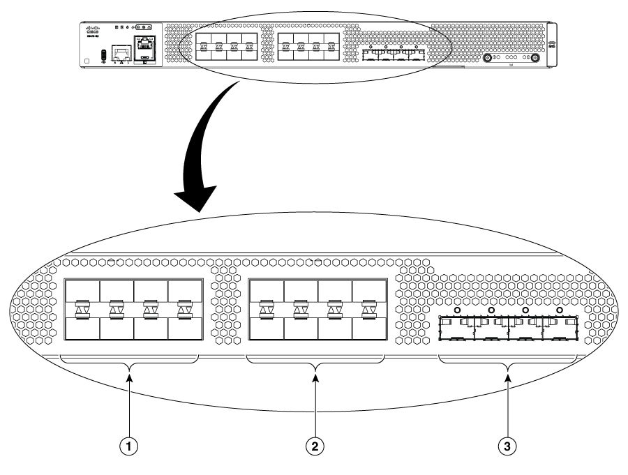
The C8475-G2 router has SFP, SFP+, and SFP28 ports.

  • Bay 0 (0/0/0 - 0/0/7) ports support SFP transceivers with maximum 1 Gbps speed.

  • Bay 0 (0/0/9 - 0/0/15) ports support SFP or SFP+ transceivers with 1 Gbps and 10 Gbps speeds, respectively.

  • Bay 0 (0/0/16 - 0/0/19) ports support SFP+ or SFP28 transceivers, with 10 Gbps and 25 Gbps speeds, respectively.

Figure 1. GE and SFP ports

1

8X 1GE SFP Ports (0/0/0 - 0/0/7)

2

8X 1/10G SFP Ports (0/0/9 - 0/0/15)

3

4X 10/25G SFP Ports (0/0/16 - 0/0/19)

Ethernet ports on C8455-G2 Secure Router

The C8455-G2 Secure Router has these ports:

GE and SFP ports

Management ethernet port

The C8455-G2 router has one Gigabit Ethernet management ethernet interface. The purpose of this interface is to allow users to perform management tasks on the router, often through Telnet andSSH. It is not designed to forward network traffic. The Gigabit Ethernet management ethernet interface supports 10/100/1000 Mbps speed.

SFP ports

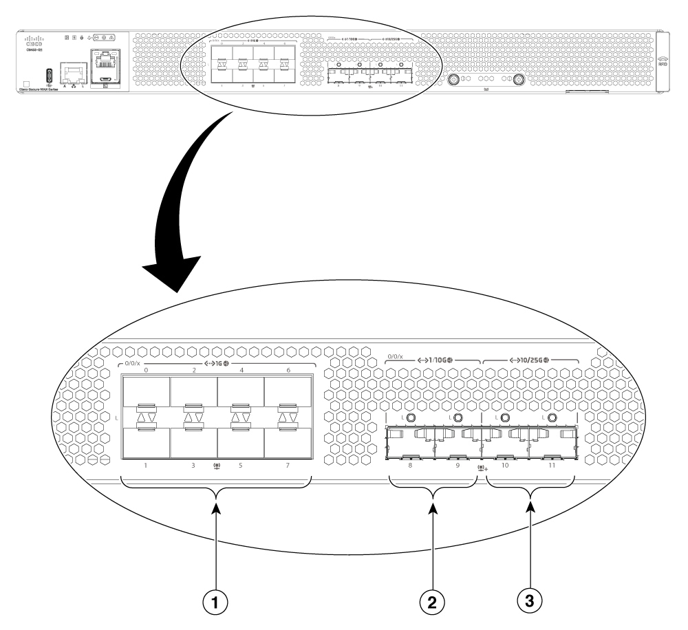
The C8455-G2 router has SFP, SFP+, and SFP28 ports.

  • Bay 0 (0/0/0 - 0/0/7) ports support SFP transceivers with maximum 1Gbps speed.

  • Bay 0 (0/0/8 - 0/0/9) ports support SFP or SFP+ transceivers with 1Gbps and 10Gbps speeds, respectively.

  • Bay 0 (0/0/10 - 0/0/11) ports support SFP+ or SFP28 transceivers with 10Gbps and 25Gbps speeds, respectively.

Figure 2. GE and SFP ports

1

8X 1GE SFP Ports (0/0/0-0/0/7)

2

2X 1/10G SFP Ports (0/0/8-0/0/9)

3

2X 10/25G SFP Ports (0/0/10-0/0/11)

Chassis views for C8475-G2 Secure Router

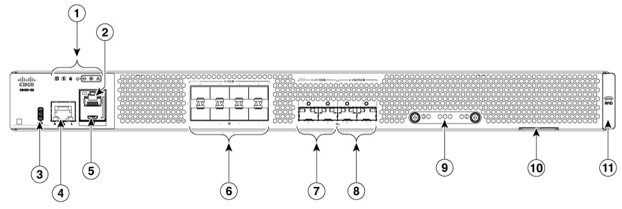
Figure 3. C8475-G2 Chassis - I/O Side
Table 4. I/O Side

1

Status indicator LEDs

2

RJ45 console port

3

USB port

4

Gigabit Ethernet management port

5

Micro-USB console

6

SFP ports (0/0/0-0/0/7)

7

SFP+ ports (0/0/8-0/0/15)

8

SFP28 ports (0/0/16-0/0/19)

9

Device label tray

10

M.2 storage slot

11

RFID (Provisionable)

LEDs for C8475-G2 Secure Router

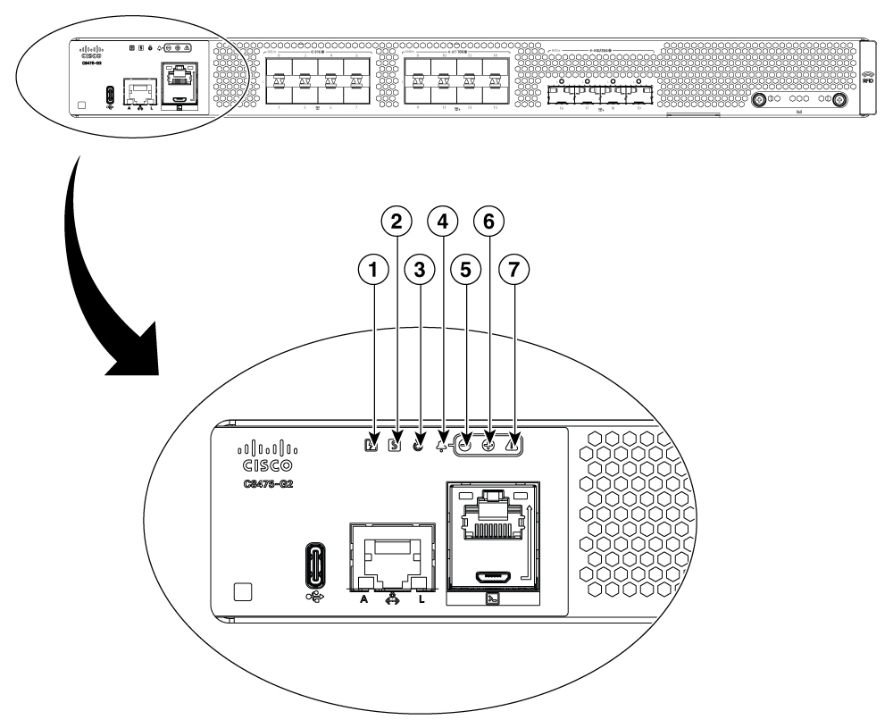
Figure 4. LEDs for C8475-G2 Secure Router

1

Power

2

Status

3

Blue beacon

4

Alarm icon (not lit)

5

Minor alarm

6

Major alarm

7

Critical alarm

Table 5. LEDs Indicators

LED

Color

Description

PSU

Green/Amber

Power Supply Status

Off: The system is powered off.

Amber: A power supply has malfunctioned (or is not installed).

Green: Both installed power supplies are operating correctly.

Status

Green/Amber/Red

System Status

Blinking Amber: The system is booting ROMMON.

Amber: System is at ROMMON prompt or booting router software.

Green: Normal System Operation.

Blinking Red: The system has failed a hardware integrity check.

Beacon

Blue

Beacon LED

Blinking Blue: Beacon requested.

Minor Alarm

Amber

Minor Alarm

Off: No Minor Alarm.

Amber: Minor Alarm Asserted.

Major Alarm

Red

Major Alarm

Off: No Major Alarm.

Red: Major Alarm Asserted.

Critical Alarm

Red

Critical Alarm

Off: No Critical Alarm.

Red: Critical Alarm Asserted.

Link

Green

RJ-45 Management Ethernet Link LED

Off: No link.

Green: Ethernet cable present and link established with other side.

Activity

Green

RJ-45 Management Ethernet Activity LED

Blinking Green: Ethernet activity detected.

USB con

Green

USB Console Active

Green: indicates that the active console port is USB.

When this is “On” the SER CON LED will be “Off”.

SER con

Green

Serial Console Active

Green: indicates that the active console port is RJ-45.

When this is “On” the USB CON LED will be “Off”.

SFP

Green/Amber

SFP port 0/1 Link LED

Off: SFP not present or port not configured (i.e., admin down).

Amber: Link down / Loss of Signal.

Green: Link established.

C8475-G2 summary

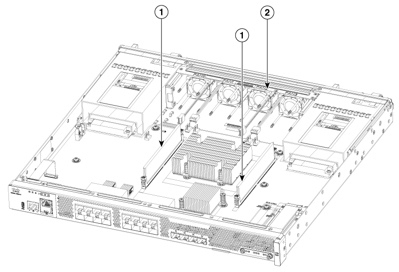
The figure below shows the internal view of C8475-G2 router with parts and module locations.

Figure 5. Summary of C8475-G2

1

DIMMs

2

Fan tray

Chassis views for C8455-G2 Secure Router

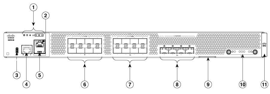
Figure 6. C8455-G2 Chassis - I/O Side
Table 6. I/O Side

1

Status indicator LEDs

2

RJ45 console port

3

USB type C port

4

GigabitEthernet management port

5

Micro-USB console

6

SFP ports (0/0/0-0/0/7)

7

SFP+ ports (0/0/8-0/0/9)

8

SFP28 ports (0/0/10-0/0/11)

9

M.2 USB/NVMe card slot

10

Device label tray

11

RFID (Provisionable)

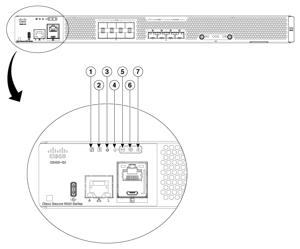
LEDs for C8455-G2 Secure Router

Figure 7. LEDs for C8455-G2 Secure Router

1

Power

2

Status

3

Blue Beacon

4

Alarm icon (not lit)

5

Minor Alarm

6

Major Alarm

7

Critical Alarm

Table 7. LED indicators

LED

Color

Description

PSU

Green/Amber

Power Supply Status

Off: The system is powered off.

Amber: A power supply has malfunctioned (or is not installed).

Green: Both installed power supplies are operating correctly.

STATUS

Green/Amber/Red

System Status

Blinking Amber: The system is booting ROMMON.

Amber: System is at ROMMON prompt or booting platform software.

Green: Normal System Operation.

Blinking Red: The system has failed a hardware integrity check.

BEACON

Blue

Beacon LED

Blinking Blue: Beacon requested.

MINOR ALARM

Amber

Minor Alarm

Off: No Minor Alarm.

Amber: Minor Alarm Asserted.

MAJOR ALARM

Red

Major Alarm

Off: No Major Alarm.

Red: Major Alarm Asserted.

CRITICAL ALARM

Red

Critical Alarm

Off: No Critical Alarm.

Red: Critical Alarm Asserted.

LINK

Green

RJ-45 Management Ethernet Link LED

Off: No link.

Green: Ethernet cable present and link established with other side.

ACTIVITY

Green

RJ-45 Management Ethernet Activity LED

Blinking Green: Ethernet activity detected.

USB CON

Green

USB Console Active

Green: indicates that the active console port is USB.

When this is “On” the SER CON LED will be “Off”.

SER CON

Green

Serial Console Active

Green: indicates that the active console port is RJ-45.

When this is “On” the USB CON LED will be “Off”.

SFP

Green/Amber

SFP port 0/1 Link LED

Off: SFP not present or port not configured (i.e., admin down).

Amber: Link down / Loss of Signal.

Green: Link established.

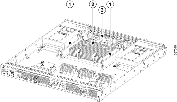
C8455-G2 summary

The figure below shows the internal view of with parts and module locations.

Figure 8. Summary of C8455-G2

1

DIMMs

2

Fan tray

Chassis ventilation

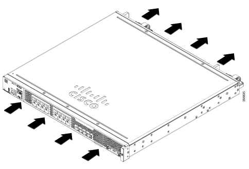
The chassis temperature is regulated with internal fans. An onboard temperature sensor and pressure sensor controls the fan speed. The fans are always on when the device is powered on. Under all conditions, the fans operate at the slowest speed possible to conserve power and reduce noise. The fans operate at higher speeds under conditions of higher ambient temperature and altitude or under fault conditions like a fan failure. The air intake is on the I/O side.

Figure 9. Airflow of Cisco 8400 Series Secure Routers

Locate labels

Use the Cisco Product Identification (CPI) tool to find labels on the platform. The tool provides detailed illustrations and descriptions of where labels are located on Cisco products. It includes the following features:

  • A search option that allows browsing for models by using a tree-structured product hierarchy.

  • A search field on the final results page that makes it easier to look up multiple products.

  • End-of-sale products clearly identified in results lists.

The tool streamlines the process of locating serial number labels and identifying products. Serial number information expedites the entitlement process and is required for access to support services.

Location of labels on Cisco C8400 Secure Routers

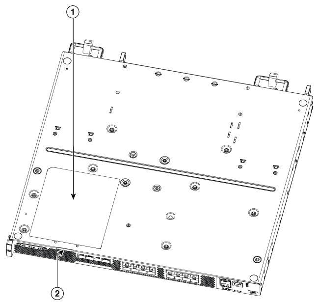
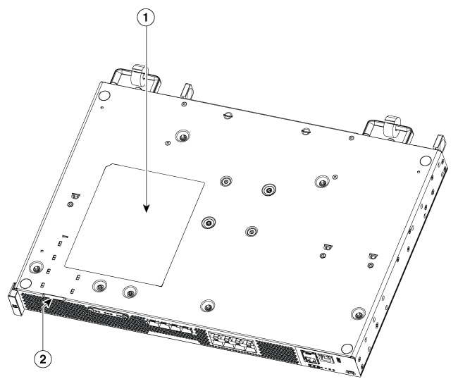
The figures below shows the location of the labels on the Cisco 8400 Series Secure Routers.

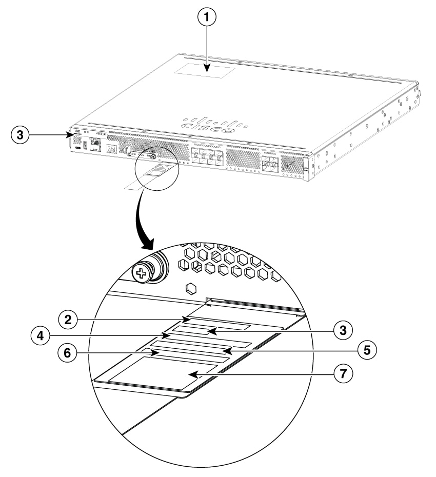
The Serial number (SN), Common language equipment identifier (CLEI), Tax deduction and collection account (TAN), Product ID (PID), PID version ID (VID), and Quick response (QR) code are printed at the same location on a label tray located on the chassis on all the Cisco 8400 Secure Routers.

Figure 10. Label location on C8475-G2
Figure 11. Label location on C8455-G2

1

Compliance label

2

Label tray

3

PID location

4

SN

5

CLEI

6

TAN

7

MAC

Locate product identification details

The serial number (SN), product ID (PID), version ID (VID), and Common Language Equipment Identifier (CLEI) are printed on a label on the bottom of the device or on the label tray.

To obtain a software license, you need the unique device identifier (UDI) of the device where the license is to be installed.

The UDI has two main components:

  • Product ID (PID)

  • Serial number (SN)

The UDI can be viewed using the show license udi command in privileged Exec mode in Cisco Internet Operating System (IOS) software.