Installing the Cisco ASR 903 Router as a Satellite Shelf

The chapter describes how to install the Cisco ASR 903 Router as a satellite shelf, and how to connect it to networks and external devices.

Safety Guidelines

Before you begin the installation of the Cisco ASR 903 Router as a satellite shelf, review the safety guidelines in this chapter to avoid injuring yourself or damaging the equipment.

In addition, before replacing, configuring, or maintaining the Cisco ASR 903 Router as a satellite shelf, review the safety warnings listed in Regulatory Compliance and Safety Information for the Cisco ASR 903 Router .

Standard Warning Statements

To see translations of the warnings that appear in this publication, see the Regulatory Compliance and Safety Information document that accompanied this device.


Warning

To prevent bodily injury when mounting or servicing this unit in a rack, you must take special precautions to ensure that the system remains stable. The following guidelines are provided to ensure your safety:This unit should be mounted at the bottom of the rack if it is the only unit in the rack.When mounting this unit in a partially filled rack, load the rack from the bottom to the top with the heaviest component at the bottom of the rack.When mounting this unit in a partially filled rack, load the rack from the bottom to the top with the heaviest component at the bottom of the rack.If the rack is provided with stabilizing devices, install the stabilizers before mounting or servicing the unit in the rack. Statement 1006


Warning

This unit is intended for installation in restricted access areas. A restricted access area can be accessed only through the use of a special tool, lock and key, or other means of security. Statement 1017


Warning

Ultimate disposal of this product should be handled according to all national laws and regulations. Statement 1040


Warning

To prevent the system from overheating, do not operate it in an area that exceeds the maximum recommended ambient temperature of 149°F (65°C). Statement 1047


Warning

The chassis should be mounted on a rack that is permanently affixed to the building. Statement 1049


Warning

IMPORTANT SAFETY INSTRUCTIONS: This warning symbol means danger. You are in a situation that could cause bodily injury. Before you work on any equipment, be aware of the hazards involved with electrical circuitry and be familiar with standard practices for preventing accidents. Use the statement number provided at the end of each warning to locate its translation in the translated safety warnings that accompanied this device. Statement 1071


Warning

This is a Class A Device and is registered for EMC requirements for industrial use. The seller or buyer should be aware of this. If this type was sold or purchased by mistake, it should be replaced with a residential-use type. Statement 294


Warning

This is a class A product. In a domestic environment this product may cause radio interference in which case the user may be required to take adequate measures. Statement 340


Warning

This equipment is in compliance with the essential requirements and other relevant provisions of Directive 1999/5/EC. Statement 287.


Safety Guidelines for Personal Safety and Equipment Protection

The following guidelines help ensure your safety and protect the equipment. This list does not include all the potentially hazardous situations. Therefore, you should be on alert.

  • Before moving the system, always disconnect all the power cords and interface cables.
  • Never assume that power is disconnected from a circuit; always check.
  • Before and after installation, keep the chassis area clear and dust-free.
  • Keep tools and assembly components away from walk areas where you or others could trip over them.
  • Do not work alone if potentially hazardous conditions exist.
  • Do not perform any action that creates a potential hazard to people or makes the equipment unsafe.
  • Do not wear loose clothing that may get caught in the chassis.
  • When working under conditions that may be hazardous to your eyes, wear safety glasses.

Safety Precautions for Module Installation and Removal

Be sure to observe the following safety precautions when you work on the router.

To see translations of the warnings that appear in this publication, see the Regulatory Compliance and Safety Information document that accompanied this device.


Warning

Class 1 laser product. Statement 1008


Warning

Do not stare into the beam or view it directly with optical instruments. Statement 1011


Warning

Invisible laser radiation present. Statement 1016


Warning

Hazardous network voltages are present in WAN ports regardless of whether power to the unit is OFF or ON. To avoid electric shock, use caution when working near WAN ports. When detaching cables, detach the end away from the unit first. Statement 1026


Warning

Blank faceplates and cover panels serve three important functions: they prevent exposure to hazardous voltages and currents inside the chassis; they contain electromagnetic interference (EMI) that might disrupt other equipment; and they direct the flow of cooling air through the chassis. Do not operate the system unless all cards, faceplates, front covers, and rear covers are in place. Statement 1029


Warning

Hazardous voltage or energy is present on the backplane when the system is operating. Use caution when servicing. Statement 1034


Warning

Invisible laser radiation may be emitted from disconnected fibers or connectors. Do not stare into beams or view directly with optical instruments. Statement 1051


Safety with Electricity


Warning

Before working on a chassis or working near power supplies, unplug the power cord on AC units; disconnect the power at the circuit breaker on DC units. Statement 12


Warning

Before working on equipment that is connected to power lines, remove jewelry (including rings, necklaces, and watches). Metal objects will heat up when connected to power and ground and can cause serious burns or weld the metal object to the terminals. Statement 43


Warning

Avoid using or servicing any equipment that has outdoor connections during an electrical storm. There may be a risk of electric shock from lightning. Statement 1088


Warning

Before performing any of the following procedures, ensure that power is removed from the DC circuit. Statement 1003


Warning

Read the installation instructions before connecting the system to the power source. Statement 1004


Warning

This product relies on the building’s installation for short-circuit (overcurrent) protection. Ensure that the protective device is rated: For a -48/-60 VDC installation, the wire shall be 12 AWG minimum with a 20 A branch circuit breaker. For a 24 VDC installation, the wire shall be 8 AWG minimum with a 40 A branch circuit breaker. Statement 1005


Warning

This product relies on the building’s installation for short-circuit (overcurrent) protection. For an AC installation, ensure that the branch circuit breaker is rated a maximum 20A. Statement 1005


Warning

There is the danger of explosion if the battery is replaced incorrectly. Replace the battery only with the same or equivalent type recommended by the manufacturer. Dispose of used batteries according to the manufacturer’s instructions. Statement 1015


Warning

This unit is intended for installation in restricted access areas. A restricted access area can be accessed only through the use of a special tool, lock and key, or other means of security. Statement 1017


Warning

When you connect or disconnect the power and/or alarm connector with power applied, an electrical arc can occur. This could cause an explosion in hazardous area installations. Be sure that all power is removed from the switch and any other circuits. Be sure that power cannot be accidentally turned on or verify that the area is nonhazardous before proceeding. Statement 1058


Warning

Take care when connecting units to the supply circuit so that wiring is not overloaded. Statement 1018


Warning

The plug-socket combination must be accessible at all times, because it serves as the main disconnecting device. Statement 1019


Warning

To avoid electric shock, do not connect safety extra-low voltage (SELV) circuits to telephone-network voltage (TNV) circuits. LAN ports contain SELV circuits, and WAN ports contain TNV circuits. Some LAN and WAN ports both use RJ-45 connectors. Use caution when connecting cables. Statement 1021


Warning

A readily accessible two-poled disconnect device must be incorporated in the fixed wiring. Statement 1022


Warning

To reduce the risk of fire, use only 26 AWG or larger telecommunication line cord. Statement 1023


Warning

This equipment must be grounded. Never defeat the ground conductor or operate the equipment in the absence of a suitably installed ground conductor. Contact the appropriate electrical inspection authority or an electrician if you are uncertain that suitable grounding is available. Statement 1024


Warning

Use copper conductors only. Statement 1025


Warning

This unit might have more than one power supply connection. All connections must be removed to de-energize the unit. Statement 1028


Warning

To prevent personal injury or damage to the chassis, never attempt to lift or tilt the chassis using the handles on modules (such as power supplies, fans, or cards); these types of handles are not designed to support the weight of the unit. Statement 1032


Warning

Connect the unit only to DC power source that complies with the safety extra-low voltage (SELV) requirements in IEC 60950 based safety standards. Statement 1033


Warning

Do not use this product near water; for example, near a bath tub, wash bowl, kitchen sink or laundry tub, in a wet basement, or near a swimming pool. Statement 1035


Warning

Never install telephone jacks in wet locations unless the jack is specifically designed for wet locations. Statement 1036


Warning

Before opening the unit, disconnect the telephone-network cables to avoid contact with telephone-network voltages. Statement 1041


Warning

This product requires short-circuit (overturned) protection, to be provided as part of the building installation. Install only in accordance with national and local wiring regulations. Statement 1045


Warning

When installing or replacing the unit, the ground connection must always be made first and disconnected last. Statement 1046


Warning

Never install an AC power module and a DC power module in the same chassis. Statement 1050


Warning

When you connect or disconnect the power and/or alarm connector with power applied, an electrical arc can occur. This could cause an explosion in hazardous area installations. Be sure that all power is removed from the switch and any other circuits. Be sure that power cannot be accidentally turned on or verify that the area is nonhazardous before proceeding. Statement 1058


Warning

This equipment is intended to be grounded to comply with emission and immunity requirements. Ensure that the switch functional ground lug is connected to earth ground during normal use. Statement 1064


Warning

If you connect or disconnect the console cable with power applied to the switch or any device on the network, an electrical arc can occur. This could cause an explosion in hazardous location installations. Be sure that power is removed or the area is nonhazardous before proceeding. Statement 1080


Warning

Installation of the equipment must comply with local and national electrical codes. Statement 1074


Warning

Hazardous voltage or energy may be present on power terminals. Always replace cover when terminals are not in service. Be sure uninsulated conductors are not accessible when cover is in place. Statement 1086


When working on equipment powered by electricity, follow these guidelines:

  • Locate the room’s emergency power-off switch. If an electrical accident occurs, you will be able to quickly turn off the power.
  • Before working on the system, turn off the DC main circuit breaker and disconnect the power terminal block cable.
  • Before doing the following, disconnect all power:
    • Working on or near power supplies
    • Installing or removing a router chassis or network processor module
    • Performing most hardware upgrades
  • Never install equipment that appears damaged.
  • Carefully examine your work area for possible hazards, such as moist floors, ungrounded power extension cables, and missing safety grounds.
  • Never assume that power is disconnected from a circuit; always check.
  • Never perform any action that creates a potential hazard to people or makes the equipment unsafe.
  • If an electrical accident occurs, proceed as follows:
    • Use caution, and do not become a victim yourself.
    • Turn off power to the router.
    • If possible, send another person to get medical aid. Otherwise, determine the condition of the victim, and then call for help.
    • Determine whether the person needs rescue breathing or external cardiac compressions; then take appropriate action.

In addition, use the following guidelines when working with any equipment that is disconnected from a power source, but still connected to telephone wiring or network cabling:

  • Never install telephone wiring during a lightning storm.
  • Never install telephone jacks in wet locations unless the jack is specifically designed for it.
  • Never touch uninsulated telephone wires or terminals unless the telephone line is disconnected at the network interface.
  • When installing or modifying telephone lines, use caution.

Power Supply Considerations

Check the power at your site to ensure that you are receiving clean power (free of spikes and noise). Install a power conditioner if necessary.


Warning

This equipment has been designed for connection to TN and IT power systems. Statement 1007


Preventing ESD Damage


Warning

This equipment needs to be grounded. Use a green and yellow 6 AWG ground wire to connect the host to earth ground during normal use. Statement 383


Electrostatic discharge (ESD) can damage equipment and impair electrical circuitry. ESD can occur when electronic printed circuit cards are improperly handled and can cause complete or intermittent failures. When removing and replacing modules, always follow ESD prevention procedures:

  • Ensure that the router chassis is electrically connected to earth ground.
  • Wear an ESD-preventive wrist strap, ensuring that it makes good skin contact. To channel unwanted ESD voltages safely to ground, connect the clip to an unpainted surface of the chassis frame. To guard against ESD damage and shocks, the wrist strap and cord must operate effectively.
  • If no wrist strap is available, ground yourself by touching a metal part of the chassis.
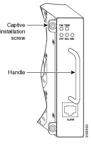
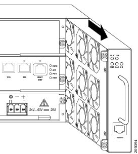
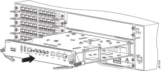
  • When installing a component, use any available ejector levers or captive installation screws to properly seat the bus connectors in the backplane or midplane. These devices prevent accidental removal, provide proper grounding for the system, and help to ensure that bus connectors are properly seated.
  • When removing a component, use available ejector levers or captive installation screws, if any, to release the bus connectors from the backplane or midplane.
  • Handle components by their handles or edges only; do not touch the printed circuit boards or connectors.
  • Place a removed component board side up on an antistatic surface or in a static-shielding container. If you plan to return the component to the factory, immediately place it in a static-shielding container.
  • Avoid contact between the printed circuit boards and clothing. The wrist strap only protects components from ESD voltages on the body; ESD voltages on clothing can still cause damage.
  • Never attempt to remove the printed circuit board from the metal carrier.

Note

For the safety of your equipment, periodically check the resistance value of the antistatic wrist strap. It should be between 1 and 10 Mohm.

Site Planning

These sections describe how to plan for the installation of the Cisco ASR 903 Router as a satellite shelf:

General Precautions

Observe the following general precautions when using and working with your Cisco ASR 903 Router as a satellite shelf system:

  • Keep the system components away from radiators and heat sources and do not block cooling vents.
  • Do not spill food or liquids on the system components and never operate the product in a wet environment.
  • Do not push any objects into the openings of the system components. Doing so can cause fire or electric shock by shorting out interior components.
  • Position system cables and power supply cables carefully. Route system cables and the power supply cable and plug so that they cannot be stepped on or tripped over. Be sure that nothing else rests on the system component cables or power cable.
  • Do not modify power cables or plugs. Consult a licensed electrician or your power company for site modifications. Always follow your local and national wiring rules.
  • If you turn off your system, wait at least 30 seconds before turning it on again to avoid system component damage.

Site Planning Checklist

Use the following checklist to perform and account for all the site planning tasks described in this chapter:

  • The site meets the environmental requirements of the Cisco ASR 903 Router as a satellite shelf.
  • The site’s air conditioning system can compensate for the heat dissipation of the Cisco ASR 903 Router as a satellite shelf.
  • The floor space that the Cisco ASR 903 occupies can support the weight of the system.
  • Electrical service to the site complies with the requirements.
  • The electrical circuit servicing the Cisco ASR 903 Router as a satellite shelf complies with the requirements.
  • Consideration has been given to the console port wiring and limitations of the cabling involved, according to TIA/EIA-232F.
  • Ethernet cabling distances for the Cisco ASR 903 Router as a satellite shelf are within limitations.
  • The equipment rack in which you plan to install the Cisco ASR 903 Router as a satellite shelf complies with requirements.
  • In selecting the location of the rack, careful consideration has been given to safety, ease of maintenance, and proper airflow.

Site Selection Guidelines

The Cisco ASR 903 Router as a satellite shelf requires specific environmental operating conditions. Temperature, humidity, altitude, and vibration can affect the performance and reliability of the router. The following sections provide specific information to help you plan for the proper operating environment.

The Cisco ASR 903 Router as a satellite shelf is designed to meet the industry EMC, safety, and environmental standards described in the Regulatory, Safety, and Compliance Information for the Cisco ASR 903 Router.

Environmental Requirements

Environmental monitoring in the Cisco ASR 903 Router as a satellite shelf protects the system and components from damage caused by excessive voltage and temperature conditions. To ensure normal operation and avoid unnecessary maintenance, plan and prepare your site configuration before installation. After installation, make sure that the site maintains the environmental characteristics described in the Cisco ASR 903 System Specifications section.

Physical Characteristics

Be familiar with the physical characteristics of the Cisco ASR 903 Router as a satellite shelf to assist you in placing the system in the proper location. For more information, see the Cisco ASR 903 System Specifications section.

AirFlow Guidelines

Cool air is circulated through the Cisco ASR 903 Router as a satellite shelf by a fan tray located along the right side of the router. Airflow is side to side, right to left, as shown in this figure.

Figure 1. Cisco ASR 903 as a Satellite Shelf Chassis Airflow

The fan trays maintain acceptable operating temperatures for the internal components by drawing in cool air through the vents, and circulating the air through the chassis.

The following guidelines will help you plan your equipment rack configuration:

  • To ensure adequate airflow through the equipment rack, we recommend that you maintain a clearance of at least 80 mm on each side of the rack at all times.
  • If airflow through the equipment rack and the routers that occupy it is blocked or restricted, or if the ambient air being drawn into the rack is too warm, an overtemperature condition can occur within the rack and the routers that occupy it.
  • The site should also be as dust-free as possible. Dust tends to clog the router fans, reducing the flow of cooling air through the equipment rack and the routers that occupy it, thus increasing the risk of an overtemperature condition.
  • Enclosed racks must have adequate ventilation. Ensure that the rack is not congested, because each router generates heat. An enclosed rack should have louvered sides and a fan to provide cooling air. Heat that is generated by the equipment near the bottom of the rack can be drawn upward into the intake ports of the equipment above.
  • When mounting a chassis in an open rack, ensure that the rack frame does not block the side intakes and the exhaust fans.
  • When rack-installed equipment fails, especially equipment in an enclosed rack, try operating the equipment by itself, if possible. Power off all other equipment in the rack (and in adjacent racks) to give the router maximum cooling air and clean power.
  • Avoid locating the Cisco ASR 903 Router as a satellite shelf in a location in which the chassis air intake vents may draw in the exhaust air from adjacent equipment. Consider how the airflows through the router; the airflow direction is side to side, with ambient air drawn in from the vents located on the front right of the chassis.

Airflow Guidelines for Enclosed Rack Installation

To install a Cisco ASR 903 Router as a satellite shelf in a 4-post enclosed cabinet, the front and rear doors of the cabinet must be removed or be perforated with a minimum of 65 percent open area (70 percent for 800-mm racks).

If you are mounting the chassis in a 4-post enclosed cabinet, ensure that you have a minimum of 6 inches (15.24 cm) of clearance on each side of the chassis.

Floor Loading Considerations

Ensure that the floor under the rack supporting the Cisco ASR 903 Router as a satellite shelf is capable of supporting the combined weight of the rack and all the other installed equipment.

To assess the weight of a fully configured Cisco ASR 903 Router as a satellite shelf, see the Cisco ASR 903 System Specifications section.

For additional information about floor loading requirements, consult GR-63-CORE, Network Equipment Building System (NEBS) Requirements: Physical Protection .

Site Power Guidelines

The Cisco ASR 903 Router as a satellite shelf has specific power and electrical wiring requirements. Adhering to these requirements ensures reliable operation of the system. Follow these precautions and recommendations when planning your site power for the Cisco ASR 903 Router as a satellite shelf:

  • The redundant power option provides a second, identical power supply to ensure that power to the chassis continues uninterrupted if one power supply fails or input power on one line fails.
  • In systems configured with the redundant power option, connect each of the two power supplies to a separate input power source. If you fail to do this, your system might be susceptible to total power failure due to a fault in the external wiring or a tripped circuit breaker.
  • To prevent a loss of input power, be sure that the total maximum load on each circuit supplying the power supplies is within the current ratings of the wiring and the breakers.
  • Check the power at your site before installation and periodically after installation to ensure that you are receiving clean power. Install a power conditioner if necessary.
  • Provide proper grounding to avoid personal injury and damage to the equipment due to lightning striking power lines or due to power surges. The chassis ground must be attached to a central office or other interior ground system.

Warning

This product requires short-circuit (overturned) protection, to be provided as part of the building installation. Install only in accordance with national and local wiring regulations. Statement 1045


Note

The installation of the Cisco ASR 903 Router as a satellite shelf must comply with all applicable codes and is approved for use with copper conductors only. The ground bond fastening hardware should be of compatible material and should preclude loosening, deterioration, and electrochemical corrosion of hardware and joined material. The chassis ground must be attached to a central office or other interior ground system using a 6-AWG gauge wire, copper ground conductor at a minimum.

The maximum power draw of the Cisco ASR 903 Router satellite shelf chassis and its configurable hardware components are listed in the following table. The maximum power draw values are not affected by whether the router chassis contains one or two AC or DC power supplies.

Hardware Component

Maximum Power Draw Value

Sat-ASR903-nV Router satellite shelf chassis with two power supplies, one fan tray, and one RSP1A

195 W

Sat-ASR903-nV Router satellite shelf chassis with two power supplies, one fan tray, and one RSP1B

210 W

A900-RSP1A-55 (standby)

100 W

A900-RSP1B-55 (standby)

100 W

A900-IMA1X (1-port 10-GE XFP interface module)

13.0 W

A900-IMA8T (8-port 1-GE RJ-45 interface module)

17.5 W

A900-IMA8S (8-port 1-GE SFP interface module)

17.5 W

Electrical Circuit Requirements

Each Cisco ASR 903 Router as a satellite shelf requires a dedicated electrical circuit. If you equip it with dual power feeds, provide a separate circuit for each power supply to avoid compromising the power redundancy feature.

The Cisco ASR 903 Router as a satellite shelf can be powered by a DC source or an AC source. Ensure that equipment grounding is present and observe the power-strip ratings. Make sure that the total ampere rating of all products plugged into the power strip does not exceed 80 percent of the rating.

For more information about the Cisco ASR 903 Router power supply, see theCisco ASR 903 Router Hardware Installation Guide.

Site Cabling Guidelines

This section contains guidelines for wiring and cabling at your site. When preparing your site for network connections to the Cisco ASR 903 Router as a satellite shelf, consider the type of cable required for each component, and the cable limitations. Consider the distance limitations for signaling, electromagnetic interference (EMI), and connector compatibility. Possible cable types are fiber, thick or thin coaxial, foil twisted-pair, or unshielded twisted-pair cabling.

Also consider any additional interface equipment you need, such as transceivers, hubs, switches, modems, channel service units (CSU), or data service units (DSU).

Before you begin, read these important notes about cabling:

  • The T1/E1 interface module for the Cisco ASR 903 Router uses a high-density connector that requires the use of a T1/E1 interface cable and a customer-provided patch panel. For more information, see the Cisco ASR 903 Router Hardware Installation Guide . Note that the Cisco ASR 903 Router as a satellite shelf does not use the T1/E1 interface module. The Cisco ASR 903 Router as a satellite shelf supports only ethernet ports.
  • Shielded cables must be used to connect to the DB-25 alarm connector on the fan tray in order to comply with FCC/EN55022/CISPR22 Class A emissions requirements. For information about the fan tray alarm port, see the Cisco ASR 903 Router Hardware Installation Guide.

Before you install the Cisco ASR 903 Router as a satellite shelf, have all the additional external equipment and cables on hand. For information about ordering, contact a Cisco customer service representative.

The extent of your network and the distances between the network interface connections depend in part on the following factors:

  • Signal type
  • Signal speed
  • Transmission medium

The distance and rate limits referenced in the following sections are the IEEE-recommended maximum speeds and distances for signaling purposes. Use this information as a guideline in planning your network connections >prior to installing the Cisco ASR 903 Router as a satellite shelf.

If wires exceed the recommended distances, or if wires pass between buildings, give special consideration to the effect of a lightning strike in your vicinity. The electromagnetic pulse caused by lightning or other high-energy phenomena can easily couple enough energy into unshielded conductors to destroy electronic devices. If you have had problems of this sort in the past, you may want to consult experts in electrical surge suppression and shielding.

Asynchronous Terminal Connections

The RSP provides a console port to connect a terminal or computer for local console access. The port has an RJ-45 connector and supports RS-232 asynchronous data with distance recommendations specified in the IEEE RS-232 standard.

Interference Considerations

When wires are run for any significant distance, there is a risk that stray signals will be induced on the wires as interference. If interference signals are strong, they can cause data errors or damage to the equipment.

The following sections describe sources of interference and how to minimize its effects on the Cisco ASR 903 system.

Electromagnetic Interference

All equipment powered by AC current can propagate electrical energy that can cause EMI and possibly affect the operation of other equipment. The typical sources of EMI are equipment power cords and power service cables from electric utility companies.

Strong EMI can destroy the signal drivers and receivers in the Cisco ASR 903 and even create an electrical hazard by causing power surges through the power lines into installed equipment. These problems are rare but could be catastrophic.

To resolve these problems, you need specialized knowledge and equipment that could consume substantial time and money. However, you can ensure that you have a properly grounded and shielded electrical environment, paying special attention to the need for electrical surge suppression.

For information about the electrode magnetic compliance standards supported on the Cisco ASR 903 Router as a satellite shelf, see Regulatory Compliance and Safety Information for the Cisco ASR 903 Router.

Radio Frequency Interference

When electromagnetic fields act over a long distance, radio frequency interference (RFI) may be propagated. Building wiring can often act as an antenna, receiving the RFI signals and creating more EMI on the wiring.

If you use twisted-pair cable in your plant wiring with a good distribution of grounding conductors, the plant wiring is unlikely to emit radio interference. If you exceed the recommended distances, use a high-quality twisted-pair cable with one ground conductor for each data signal.

Lightning and AC Power Fault Interference

If signal wires exceed the recommended cabling distances, or if signal wires pass between buildings, you should consider the effect that a lightning strike in your vicinity might have on the Cisco ASR 903 Router as a satellite shelf.

The electromagnetic pulse (EMP) generated by lightning or other high-energy phenomena can couple enough energy into unshielded conductors to damage or destroy electronic equipment. If you have previously experienced such problems, you should consult with RFI and EMI experts to ensure that you have adequate electrical surge suppression and shielding of signal cables in your Cisco ASR 903 Router as a satellite shelf operating environment.

Rack-Mounting Guidelines

These sections provide guidelines for rack-mounting the Cisco ASR 903 Router as a satellite shelf:

Rack-Mounting Precautions

These rack-mount guidelines are provided to ensure your safety:

  • Do not move large racks by yourself. Due to the height and weight of a rack, a minimum of two people are required to accomplish this task.
  • Ensure that the rack is level and stable before extending a component from the rack.
  • Ensure that proper airflow is provided to the components in the rack.
  • Do not step on or stand on any component or system when servicing other systems or components in a rack.
  • When mounting the Cisco ASR 903 Router as a satellite shelf in a partially filled rack, load the rack from the bottom to the top, with the heaviest component at the bottom of the rack.
  • If the rack is provided with stabilizing devices, install the stabilizers before mounting or servicing the unit in the rack.

Rack Selection Guidelines

The Cisco ASR 903 Router as a satellite shelf can be mounted in most two-post or four-post, 19-inch equipment racks that comply with the Electronic Industries Association (EIA) standard for equipment racks (EIA-310-D 19-inch). The rack must have at least two posts with mounting flanges to mount the chassis.


Caution

When mounting a chassis in any type of rack equipment, ensure that the inlet air to the chassis does not exceed 65 degrees C.


The distance between the center lines of the mounting holes on the two mounting posts must be 18.31 inches ± 0.06 inch (46.50 cm ± 0.15 cm). The rack-mounting hardware included with the chassis is suitable for most 19-inch equipment racks.

Consider installing the Cisco ASR 903 Router as a satellite shelf in a rack with the following features:

  • Network Equipment Building System (NEBS) compliant, 19-inch (48.3-cm) wide rack.
  • EIA or European Telecommunications Standards Institute (ETSI) hole patterns in the mounting rails. The required mounting hardware is shipped with the Cisco ASR 903. If the rack that you plan to install the system in has metric-threaded rails, you must provide your own metric-mounting hardware.
  • Perforated top and open bottom for ventilation to prevent overheating.
  • Leveling feet for stability.

Note

The Cisco ASR 903 Router as a satellite shelf should not be installed in an enclosed rack because the chassis requires an unobstructed flow of cooling air to maintain acceptable operating temperatures for its internal components. Installing the router in any type of enclosed rack—even with the side doors removed —could disrupt the airflow, trap heat next to the chassis, and cause an overtemperature condition inside the router. If you use an enclosed rack, ensure that there are air vents on all sides of the rack and there is proper ventilation.

Equipment Rack Guidelines

The placement of the rack can affect personnel safety, system maintenance, and the system’s ability to operate within the environmental characteristics described in the Cisco ASR 903 System Specifications section. Choose a proper location for the Cisco ASR 903 Router as a satellite shelf by following these guidelines.

Locating for Safety

If the Cisco ASR 903 Router as a satellite shelf is the heaviest or the only piece of equipment in the rack, consider installing it at or near the bottom to ensure that the rack’s center of gravity is as low as possible.

For additional information about the proper placement of electronic equipment, consult the document GR-63-CORE, Network Equipment Building System (NEBS) Requirements: Physical Protection.

Locating for Easy Maintenance

Keep at least 3 feet of clear space at the front and back of the rack. This space ensures that you can remove the Cisco ASR 903 Router as a satellite shelf components and perform routine maintenance and upgrades easily.

Avoid installing the Cisco ASR 903 Router as a satellite shelf in a congested rack and consider how routing of cables from other pieces of equipment in the same rack could affect access to the router cards.

The sides of the chassis must remain unobstructed to ensure adequate airflow and prevent overheating inside the chassis.

Allow the following clearances for normal system maintenance:

  • At the top of the chassis—At least 3 inches (7.6 cm)
  • Sides of the chassis—3 to 4 ft (91.44 cm to 121.92 cm)

To avoid problems during installation and ongoing operations, follow these general precautions when you plan equipment locations and connections:

  • Use the show environment all command regularly to check the internal system status. The environmental monitor continually checks the interior chassis environment; it provides warnings about high temperature and creates reports on other potentially dangerous occurrences. If warning messages are displayed, take immediate action to identify the cause, and correct the problem.
  • Keep the Cisco ASR 903 Router as a satellite shelf off the floor and out of areas that collect dust.
  • Follow ESD-prevention procedures to avoid damage to equipment. Damage from static discharge can cause immediate or intermittent equipment failure.
Locating for Proper Airflow

Ensure that the Cisco ASR 903 Router as a satellite shelf has enough airflow to keep the system operating within the environmental characteristics and the air temperature is sufficient to compensate for the heat dissipated by the system. For more information, see the AirFlow Guidelines section.

Installation Checklist

To assist you with your installation and to provide a record of what was done by whom and when, photocopy the Cisco ASR 903 Router installation checklist shown in this table. Use this to record the completion and verification of each procedure. After the checklist is completed, place it in your site log along with the other records pertaining to your new Cisco router.

Table 1. Cisco ASR 903 Router Installation Checklist

Task

Verified By

Date

Date on which chassis received

Chassis and all accessories unpacked

Types and numbers of interfaces verified

Safety recommendations and guidelines reviewed

Installation checklist copied

Site log established and background information entered

Site power voltages verified

Site environmental specifications verified

Required passwords, IP addresses, device names, and so on available

Required tools available

Network connection equipment available

Cable-management brackets installed (optional, but recommended)

AC power cables connected to AC sources and router

DC power cables connected to DC sources and router

Network interface cables and devices connected

System power turned on

System boot complete (STATUS LED is on)

Shared port adapters are operational

Correct software configuration displayed after system banner appears

Creating a Site Log

The site log provides a record of all the actions related to installing and maintaining the router. Keep it in an accessible place near the chassis so that anyone who performs tasks has access to it.

Create the site log prior to the installation. (See Site Log for more information on the site log and a sample site log that can be used to make copies.)

Receiving the Cisco ASR 903 Router

Each Cisco ASR 903 Router satellite shelf chassis is shipped in a container that is strapped to a pallet, as illustrated in this figure.

Figure 2. Cisco ASR 903 Router Packaged for Shipping

1

Outside carton

3

Packing straps

2

Pallet


Note

We recommend that you have at least two people available to help with the installation and ensure safe lifting.

Chassis-Lifting Guidelines

The chassis is not intended to be moved frequently. Before you install the system, ensure that your site is properly prepared so that you can avoid having to move the chassis later to accommodate power sources and network connections.

Two or more people are required to lift the chassis. Each time you lift the chassis or any heavy object, follow these guidelines:

  • Never attempt to lift the chassis by yourself. Because of the size and weight of the chassis, use at least two people to safely lift and move it without causing injury to yourself or damaging the equipment.
  • Ensure that your footing is solid, and balance the weight of the chassis between your feet.
  • Lift the chassis slowly; never move suddenly or twist your body as you lift.
  • Keep your back straight and lift with your legs, not your back. If you must bend down to lift the chassis, bend at the knees, not at the waist, to reduce the strain on your back muscles.
  • Do not remove installed components from the chassis.
  • Always disconnect all external cables before lifting or moving the chassis.

Warning

To prevent personal injury or damage to the chassis, never attempt to lift or tilt the chassis using the handles on modules (such as power supplies, fans, or cards); these types of handles are not designed to support the weight of the unit. Statement 1032


Perform the following to lift a chassis:

SUMMARY STEPS

  1. Each person should stand on either side of the chassis and place one hand under the air intake at the bottom front of the chassis.
  2. With the other hand, grasp the top rear of the chassis under the air exhaust, and carefully lift the chassis.

DETAILED STEPS


Step 1

Each person should stand on either side of the chassis and place one hand under the air intake at the bottom front of the chassis.

Step 2

With the other hand, grasp the top rear of the chassis under the air exhaust, and carefully lift the chassis.


Tools and Equipment

You need the following tools and equipment to install and upgrade the router and its components:

  • ESD-preventive cord and wrist strap
  • Antistatic mat or antistatic foam
  • Number 1 and Number 2 Phillips-head screwdrivers
  • Flat-blade screwdrivers: Small 3/16-inch (0.476 cm) and medium 1/4-inch (0.625 cm):
    • To install or remove modules
    • To remove the cover if you are upgrading the memory or other components
  • #12-24 pan-head screws to secure the router to the equipment rack
  • Cables for connecting to the WAN and LAN ports (depending on the configuration)

Note

For more information on cable specifications, see the Cisco ASR 903 Series Aggregation Services Router Hardware Installation Guide.
  • Ethernet hub or switch or PC with a network interface card for connecting to the Ethernet ports
  • Console terminal (an ASCII terminal or a PC running terminal emulation software) that is configured for 9600 baud, 8 data bits, no parity, and 2 stop bits
  • Console cable for connecting to the console port
  • (Optional) Modem for connecting to the auxiliary port for remote administrative access
  • Auxiliary cable for connecting to the auxiliary port (you can supply this cable or order one)
  • Ratcheting torque screwdriver with a Phillips head that exerts up to 30 pound-force per square inch (lbf/sq in) of pressure
  • Crimping tool as specified by the ground lug manufacturer
  • 18-AWG copper wire for the power cord
  • Wire-stripping tools for stripping both 6-AWG and 18-AWG wire
  • Tape measure and level

Warning

Only trained and qualified personnel should be allowed to install, replace, or service this equipment. Statement 1030


Unpacking and Verifying the Shipped Contents

When you receive your chassis, perform the following steps and use the Shipping Contents Checklist:

  1. Inspect the box for any shipping damage. If there is obvious physical damage, contact your Cisco service representative.

  2. Unpack the Cisco ASR 903 Router satellite shelf.

  3. Perform a visual inspection of the chassis.

  4. Use this table to check the contents of the Cisco ASR 903 Router as a satellite shelf shipping container. Do not discard the shipping container. You will need the container if you move or ship the Cisco ASR 903 Router as a satellite shelf in the future.

Table 2. Cisco ASR 903 Router Satellite Shelf Shipping Container Contents

Component

Description

Chassis

Cisco ASR 903 Router satellite shelf chassis

Fan tray

Power supplies

RSP

Interface modules

Accessories kit

Chassis rack-mount brackets (19-inch EIA)

Three sets of screws:

  • Front and rear rack-mount bracket screws (two sets)

  • Cable-management bracket screws

Six cable-management brackets (one per bracket)

One earth lug with two 10-32 screws.

1 RJ-45 to RJ-45 crossover cable

1 RJ-45 to DB-9 (female) adapter

ESD, wrist strap (disposable)

One disposable wrist strap (optional)

Documentation

Regulatory Compliance and Safety Information for the Cisco ASR 903 Router

Optional equipment

Check the container for the following optional equipment:

  • Power cord if an AC power supply was shipped. There are no cords for the DC power supply units.

  • T1/E1 cable connector (required only for T1/E1 interface modules)


Note

Most Cisco documentation is available online. Documentation that is shipped with your Cisco ASR 903 includes the Regulatory Compliance and Safety Information for the Cisco ASR 903 Router document and Cisco ASR 903 Documentation Roadmap which contains information about the various documents that are available online and the links to them.

Installing the Router in a Rack

These sections describe how to install the Cisco ASR 903 Router in a rack:

Installing the Chassis Brackets

The chassis is shipped with mounting brackets that can be installed on the front or rear of the chassis. To install the brackets on the front of the chassis, perform these steps:

SUMMARY STEPS

  1. Remove the rack-mount brackets from the accessory kit and position them beside the router chassis.
  2. Position one of the brackets against the chassis side, and align the screw holes.
  3. Secure the bracket to the chassis with the screws removed when performing Step 1 . The recommended maximum torque is 28 lbf/sq in.
  4. Repeat Step 2 and Step 3 for the other bracket.

DETAILED STEPS


Step 1

Remove the rack-mount brackets from the accessory kit and position them beside the router chassis.

This figure shows how to attach the brackets on the Cisco ASR 903 Router as a satellite shelf for a 19-inch EIA rack.

Figure 3. Attaching Mounting Brackets for a 19-Inch EIA Rack

Figure 4-4 shows how to attach the brackets on the Cisco ASR 903 Router as a satellite shelf for a 300-mm ETSI cabinet.

Figure 4. Attaching Mounting Brackets for a 300 -mm ETSI Cabinet
Step 2

Position one of the brackets against the chassis side, and align the screw holes.

Step 3

Secure the bracket to the chassis with the screws removed when performing Step 1 . The recommended maximum torque is 28 lbf/sq in.

Step 4

Repeat Step 2 and Step 3 for the other bracket.


Installing the Router Chassis in the Rack

To install the router chassis in the equipment rack, perform these steps:

SUMMARY STEPS

  1. Position the chassis in the rack as follows:
  2. Align the mounting holes in the bracket (and optional cable guide) with the mounting holes in the equipment rack.
  3. Install the 8 or 12 (4 or 6 per side) 12-24 x 3/4-inch or 10-32 x 3/4-inch screws through the holes in the bracket and into the threaded holes in the equipment rack posts.
  4. Use a tape measure and level to verify that the chassis is installed straight and level.

DETAILED STEPS


Step 1

Position the chassis in the rack as follows:

  • If the front of the chassis (front panel) is at the front of the rack, insert the rear of the chassis between the mounting posts.
  • If the rear of the chassis is at the front of the rack, insert the front of the chassis between the mounting posts.
Step 2

Align the mounting holes in the bracket (and optional cable guide) with the mounting holes in the equipment rack.

Caution 

Do not use interface-module and power-supply ejector handles to lift the chassis; using the handles to lift the chassis can deform or damage the handles.

Figure 5. Installing the Chassis in a 19-Inch EIA Rack
Figure 6. Installing the Chassis to Support the Japanese JIS Rack Standard
Figure 7. Installing the Chassis in a 300-mm ETSI Cabinet
Step 3

Install the 8 or 12 (4 or 6 per side) 12-24 x 3/4-inch or 10-32 x 3/4-inch screws through the holes in the bracket and into the threaded holes in the equipment rack posts.

Step 4

Use a tape measure and level to verify that the chassis is installed straight and level.


Attaching the Cable Management Brackets

To install the optional cable management brackets, perform these steps:

SUMMARY STEPS

  1. Position the cable management brackets against the front of the chassis and align the four screw holes, as shown in this figure.
  2. Secure the cable management brackets with four M4 screws. The recommended maximum torque is 10 lbf/sq in.

DETAILED STEPS


Step 1

Position the cable management brackets against the front of the chassis and align the four screw holes, as shown in this figure.

Figure 8. Cable Management Bracket Installation
Step 2

Secure the cable management brackets with four M4 screws. The recommended maximum torque is 10 lbf/sq in.


Installing the Chassis Ground Connection

Before you connect the power or turn on the power to the Cisco ASR 903 Router as a satellite shelf, you must provide an adequate chassis ground (earth) connection to your router.

This section describes how to ground the Cisco ASR 903 Router satellite shelf chassis. The router provides two locations for attaching a 2-hole grounding lug according to the rack-mounting brackets you use to install the router. The Cisco ASR 903 Router as a satellite shelf supports the following rack-mounting types:

  • EIA 19-inch rack—Attach the grounding lug to the rear of the router, as shown in this figure.
Figure 9. Attaching a Grounding Lug to the Rear of the Router

1

Grounding lug (19-inch EIA rack)

  • 300-mm ETSI cabinet—Attach the grounding lug on the rack-mount bracket on the front of the router, as shown in this figure.
Figure 10. Attaching a Grounding Lug to the Rack-Mount Bracket

1

Grounding lug (3000-mm ETSI cabinet)

To ensure that the chassis ground connection that you provide is adequate, you need the following parts and tools:

  • Ratcheting torque screwdriver with Phillips head that exerts up to 15 lbf/sq in. of pressure for attaching the ground wire to the router
  • Crimping tool as specified by the ground lug manufacturer
  • 18-AWG copper wire for the power cord
  • 6-AWG or larger copper wire for the ground wire
  • Wire-stripping tools appropriate to the wire that you are using

Caution

Before making connections to the Cisco ASR 903 Router as a satellite shelf, ensure that you disconnect the power at the circuit breaker. Otherwise, severe injury to you or damage to the router may occur.


Warning

This equipment must be grounded. Never defeat the ground conductor or operate the equipment in the absence of a suitably installed ground conductor. Contact the appropriate electrical inspection authority or an electrician if you are uncertain that suitable grounding is available. Statement 1024


Warning

Use copper conductors only. Statement 1025


Warning

When installing or replacing the unit, the ground connection must always be made first and disconnected last. Statement 1046


This unit is to be installed in a restrictive access location and must be permanently grounded to minimum 6-AWG copper ground wire.

Installing the Chassis Ground

Perform the following procedure to ground the Cisco ASR 903 Router as a satellite shelf using a 2-hole lug and the corresponding mounting point. Most carriers require a minimum 6-AWG ground connection. Verify your carrier’s requirements for the ground connection.

SUMMARY STEPS

  1. If your ground wire is insulated, use a wire-stripping tool to strip the ground wire to 0.5 inch ± 0.02 inch (12.7 mm ±0.5 mm).
  2. Slide the open end of your 2-hole ground lug over the exposed area of the ground wire.
  3. Using a crimping tool (as specified by the ground lug manufacturer), crimp the ground lug to the ground wire as shown in this figure.
  4. Use a Phillips head screwdriver to attach the 2-hole ground lug and wire assembly to the router with the 2 pan-head Phillips head screws. For a 19-inch EIA rack, attach the 2-hole ground lug to the rear of the router.
  5. Connect the other end of the ground wire to a suitable grounding point at your site.

DETAILED STEPS


Step 1

If your ground wire is insulated, use a wire-stripping tool to strip the ground wire to 0.5 inch ± 0.02 inch (12.7 mm ±0.5 mm).

Figure 11. Stripping a Ground Wire
Step 2

Slide the open end of your 2-hole ground lug over the exposed area of the ground wire.

Step 3

Using a crimping tool (as specified by the ground lug manufacturer), crimp the ground lug to the ground wire as shown in this figure.

Figure 12. Crimping a Ground Lug onto the Ground Wire
Step 4

Use a Phillips head screwdriver to attach the 2-hole ground lug and wire assembly to the router with the 2 pan-head Phillips head screws. For a 19-inch EIA rack, attach the 2-hole ground lug to the rear of the router.

Step 5

Connect the other end of the ground wire to a suitable grounding point at your site.


Installing the Fan Tray

The fan tray is a modular unit that provides cooling to the Cisco ASR 903 Router as a satellite shelf. Follow these steps to install the fan tray in the chassis:

SUMMARY STEPS

  1. Orient the fan tray so that the captive screws are on the left side of the fan tray’s front panel. This figure shows how to orient the fan tray.
  2. Guide the fan tray into the chassis until it is fully seated.
  3. Secure the fan tray to the chassis using the attached captive installation screws. The recommended maximum torque is 5.5 lbf/sq in.

DETAILED STEPS


Step 1

Orient the fan tray so that the captive screws are on the left side of the fan tray’s front panel. This figure shows how to orient the fan tray.

Figure 13. Installing the Fan Tray
Step 2

Guide the fan tray into the chassis until it is fully seated.

Caution 

The fans are exposed on the left side of the fan tray. Keep your fingers, clothing, and jewelry away from the fans. Always handle the fan tray by the handle.

Step 3

Secure the fan tray to the chassis using the attached captive installation screws. The recommended maximum torque is 5.5 lbf/sq in.

For information about connecting cables to the fan tray alarm port, see the Connecting the Fan Tray Alarm Port section. For a summary of the LEDs on the fan tray, see the Fan Tray LEDs section. For more information about airflow guidelines, see the AirFlow Guidelines section.


Removing and Replacing the Fan Tray

The fan tray supports online insertion and removal (OIR). There is no need to power down the Cisco ASR 903 Router as a satellite shelf to remove or replace the fan tray. However, the router will shut down if the fan tray is removed from the chassis for more than five minutes.


Caution

The router can stay active for up to five minutes if the temperature is below the ambient limit. However, in the event of an overtemperature alarm, the router can shut down in less than five minutes. In the event of a critical temperature alarm, the router shuts down immediately.


Follow these steps to remove and replace the fan tray on the Cisco ASR 903 Router as a satellite shelf:

SUMMARY STEPS

  1. Using a No. 2 Phillips screwdriver or your fingers, loosen the captive installation screw that secures the fan tray to the chassis. This figure shows the front of the fan tray, including the captive installation screws.
  2. Grasp the fan tray handle with one hand and the outside of the chassis with the other hand. The figure above shows the front of the fan tray, including the handle.
  3. Pull the fan tray backward toward you no more than 1 inch to disengage it from the power receptacle on the midplane, as shown in this figure .
  4. Wait at least 5 seconds to allow the fans to stop spinning. Then, pull the fan tray backward toward you and out of the chassis.

DETAILED STEPS


Step 1

Using a No. 2 Phillips screwdriver or your fingers, loosen the captive installation screw that secures the fan tray to the chassis. This figure shows the front of the fan tray, including the captive installation screws.

Figure 14. Detaching the Fan Tray
Step 2

Grasp the fan tray handle with one hand and the outside of the chassis with the other hand. The figure above shows the front of the fan tray, including the handle.

Caution 

The fans are exposed on the left side of the fan tray. Keep your fingers, clothing, and jewelry away from the fans. Always handle the fan tray by the handle.

Step 3

Pull the fan tray backward toward you no more than 1 inch to disengage it from the power receptacle on the midplane, as shown in this figure .

Figure 15. Fan Tray Removal
DANGER 

The fans might still be turning when you remove the fan assembly from the chassis. Keep fingers, screwdrivers, and other objects away from the openings in the fan assembly’s housing. Statement 263

Step 4

Wait at least 5 seconds to allow the fans to stop spinning. Then, pull the fan tray backward toward you and out of the chassis.

As the fan tray slides out the chassis, support the bottom of the fan tray with one hand and keep your other hand on the fan tray handle. To install the new fan tray, follow the steps in the Installing the Fan Tray section.


Installing and Removing an RSP Module

Follow these steps on handling an RSP module in the Cisco ASR 903 Router as a satellite shelf:

Installing an RSP Module

To install an RSP module in the router chassis, perform the following steps:

SUMMARY STEPS

  1. Choose a slot for the module. Make sure that there is enough clearance to accommodate any equipment that will be connected to the ports on the module. If a blank module filler plate is installed in the slot in which you plan to install the module, remove the plate by removing its two Phillips pan-head screws.
  2. Fully open both the ejector levers on the new module, as shown in this figure.
  3. Position the module in the slot. Make sure that you align the sides of the module with the guides on each side of the slot, as shown in this figure.
  4. Carefully slide the module into the slot until the EMI gasket on the module makes contact with the module in the adjacent slot and both the ejector levers have closed to approximately 45 degrees with respect to the module faceplate.
  5. While pressing down, simultaneously close both the ejector levers to fully seat the module in the backplane connector. The ejector levers are fully closed when they are flush with the module faceplate.
  6. Tighten the two captive installation screws on the module. The recommended maximum torque is 5.5 lbf/sq in.
  7. Verify that the captive installation screws are tightened on all of the modules installed in the chassis. This step ensures that the EMI gaskets on all the modules are fully compressed in order to maximize the opening space for the new or replacement module.

DETAILED STEPS


Step 1

Choose a slot for the module. Make sure that there is enough clearance to accommodate any equipment that will be connected to the ports on the module. If a blank module filler plate is installed in the slot in which you plan to install the module, remove the plate by removing its two Phillips pan-head screws.

Step 2

Fully open both the ejector levers on the new module, as shown in this figure.

Caution 

To prevent ESD damage, handle modules by carrier edges only.

Step 3

Position the module in the slot. Make sure that you align the sides of the module with the guides on each side of the slot, as shown in this figure.

Figure 16. Cisco ASR 903 RSP Installation
Step 4

Carefully slide the module into the slot until the EMI gasket on the module makes contact with the module in the adjacent slot and both the ejector levers have closed to approximately 45 degrees with respect to the module faceplate.

Caution 

If the top slot already has an RSP module installed, and you install a second RSP module in the slot below it, be careful during insertion not to damage the EMI gasket of the bottom RSP module against the ejector levers of the top RSP.

Step 5

While pressing down, simultaneously close both the ejector levers to fully seat the module in the backplane connector. The ejector levers are fully closed when they are flush with the module faceplate.

Step 6

Tighten the two captive installation screws on the module. The recommended maximum torque is 5.5 lbf/sq in.

Note 
Make sure that the ejector levers are fully closed before tightening the captive installation screws.
Step 7

Verify that the captive installation screws are tightened on all of the modules installed in the chassis. This step ensures that the EMI gaskets on all the modules are fully compressed in order to maximize the opening space for the new or replacement module.

If the captive installation screws are loose, the EMI gaskets on the installed modules will push adjacent modules toward the open slot, which reduces the size of the opening and makes it difficult to install the new module.

Blank module filler plates (Cisco part number A900-RSPA-BLANK) should be installed in any empty chassis slots to keep dust out of the chassis and to maintain consistent airflow through the chassis.


Removing an RSP Module

Before you remove an RSP from the router, you should save the current configuration using the write {host file | network | terminal} command. This saves you time when bringing the module back online.

If the module is running Cisco IOS software, save the current running configuration by entering the copy running-config startup-config command.


Warning

Hazardous voltage or energy is present on the backplane when the system is operating. Use caution when servicing. Statement 1034


Warning

Invisible laser radiation may be emitted from disconnected fibers or connectors. Do not stare into beams or view directly with optical instruments. Statement 1051


To remove an RSP module, perform the following steps:

SUMMARY STEPS

  1. Disconnect any cables attached to the ports on the module.
  2. Verify that the captive installation screws on all the modules in the chassis are tight. This step ensures that the space created by the removed module is maintained.
  3. Loosen the two captive installation screws on the module that you plan to remove from the chassis.
  4. Place your thumbs on the ejector levers (see the figure Cisco ASR 903 RSP Installation) and simultaneously rotate the ejector levers outward to unseat the module from the backplane connector.
  5. Grasp the front edge of the module and slide the module straight out of the slot. If the chassis has horizontal slots, place your hand under the module to support its weight as you slide it out from the slot. Do not touch the module circuitry.
  6. Place the module on an antistatic mat or antistatic foam, or immediately reinstall the module in another slot.
  7. Install blank module filler plates (Cisco part number A900-RSPA-BLANK) in empty slots, if any.

DETAILED STEPS


Step 1

Disconnect any cables attached to the ports on the module.

Step 2

Verify that the captive installation screws on all the modules in the chassis are tight. This step ensures that the space created by the removed module is maintained.

Note 
If the captive installation screws are loose, the EMI gaskets on the installed modules will push the modules toward the open slot, which in turn reduces the size of the opening and makes it difficult to remove the module.
Step 3

Loosen the two captive installation screws on the module that you plan to remove from the chassis.

Step 4

Place your thumbs on the ejector levers (see the figure Cisco ASR 903 RSP Installation) and simultaneously rotate the ejector levers outward to unseat the module from the backplane connector.

Step 5

Grasp the front edge of the module and slide the module straight out of the slot. If the chassis has horizontal slots, place your hand under the module to support its weight as you slide it out from the slot. Do not touch the module circuitry.

Caution 

To prevent ESD damage, handle modules by the carrier edges only.

Step 6

Place the module on an antistatic mat or antistatic foam, or immediately reinstall the module in another slot.

Step 7

Install blank module filler plates (Cisco part number A900-RSPA-BLANK) in empty slots, if any.

Blank faceplates and cover panels serve three important functions: they prevent exposure to hazardous voltages and currents inside the chassis; they contain electromagnetic interference (EMI) that might disrupt other equipment; and they direct the flow of cooling air through the chassis. Do not operate the system unless all cards, faceplates, front covers, and rear covers are in place. Statement 1029


Installing and Removing an Interface Module

These sections describe the various tasks of associated with interface module installation on the Cisco ASR 903 Router as a satellite shelf:

Installing an Interface Module

SUMMARY STEPS

  1. Before inserting an interface module, make sure that the chassis is grounded.
  2. To insert the interface module, carefully align the edges of the interface module between the upper and lower edges of the router slot.
  3. Carefully slide the interface module into the router slot until the interface module makes contact with the backplane. This figure shows how to install the interface module.
  4. Tighten the locking thumbscrews on both sides of the interface module. The recommended maximum torque is 5.5 lbf/sq in.
  5. Connect all the cables to each interface module.

DETAILED STEPS


Step 1

Before inserting an interface module, make sure that the chassis is grounded.

Step 2

To insert the interface module, carefully align the edges of the interface module between the upper and lower edges of the router slot.

Step 3

Carefully slide the interface module into the router slot until the interface module makes contact with the backplane. This figure shows how to install the interface module.

Figure 17. Inserting an Interface Module
Step 4

Tighten the locking thumbscrews on both sides of the interface module. The recommended maximum torque is 5.5 lbf/sq in.

Step 5

Connect all the cables to each interface module.

10 Gigabit Ethernet interface modules are not supported in slots 4 and 5. Do not use interface-module and power-supply ejector handles to lift the chassis; using the handles to lift the chassis can deform or damage the handles.


Removing an Interface Module

SUMMARY STEPS

  1. To remove an interface module, disconnect all the cables from each interface module.
  2. Loosen the locking thumbscrews on both sides of the interface module.
  3. Slide the interface module out of the router slot by pulling on the handles. If you are removing a blank filler plate, pull the blank filler plate completely out of the router slot using the captive screws.

DETAILED STEPS


Step 1

To remove an interface module, disconnect all the cables from each interface module.

Step 2

Loosen the locking thumbscrews on both sides of the interface module.

Step 3

Slide the interface module out of the router slot by pulling on the handles. If you are removing a blank filler plate, pull the blank filler plate completely out of the router slot using the captive screws.


Installing the Power Supply

The Cisco ASR 903 Router as a satellite shelf provides the choice of two different power supplies:

  • DC power—19.2VDC to –72VDC

The DC power supply uses three-position terminal block-style connector with positive latching/securing and labeled connections for +24/48V, GRD, –24/48V. The terminal block connector is of suitable size to carry the appropriate AWG wire size to handle the input current of the power supply. No ON/OFF switch is provided.

  • AC power—85 VAC to 264 VAC

The AC power supply has an IEC 320-type power receptacle and a 15-A service connector. You can use standard right angle power cords with the AC power supply. The power supply includes a power cord retainer. No ON/OFF switch is provided.

Each power supply provides a single primary input power connection. You can install dual power supplies for redundancy.


Warning

Read the installation instructions before connecting the system to the power source. Statement 1004


Note

Products that have an AC power connection are required to have an external surge protective device (SPD) provided as part of the building installation to comply with the Telcordia GR-1089 NEBS standard for electromagnetic compatibility and safety.

Caution

Do not use interface-module and power-supply ejector handles to lift the chassis; using the handles to lift the chassis can deform or damage the handles.


These sections describe the Cisco ASR 903 Router satellite shelf power supplies:

Preventing Power Loss

Use the following guidelines to prevent power loss to the router.

  • To prevent loss of input power, ensure that the total maximum load on each circuit supplying the power supplies is within the current ratings of the wiring and breakers.
  • In some systems, you can use an UPS to protect against power failures at your site. Avoid UPS types that use ferroresonant technology. These UPS types can become unstable with systems like the Cisco ASR 903 Router as a satellite shelf, which can have substantial current draw fluctuations due to bursty data traffic patterns.

Use the information in the Cisco ASR 9000v Satellite Shelf with a DC Power Module section to estimate the power requirements and heat dissipation of a Cisco ASR 903 Router as a satellite shelf based on a given configuration of the router. Determining power requirements is useful for planning the power distribution system needed to support the router.

Power Connection Guidelines

This section provides guidelines for connecting the Cisco ASR 903 Router satellite shelf power supplies to the site power source.


Warning

This equipment is intended to be grounded to comply with emission and immunity requirements. Ensure that the switch functional ground lug is connected to earth ground during normal use. Statement 1064


Warning

The plug-socket combination must be accessible at all times because it serves as the main disconnecting device. Statement 1019


Warning

This product requires short-circuit (overcurrent) protection, to be provided as part of the building installation. Install only in accordance with national and local wiring regulations. Statement 1045


Guidelines for DC-Powered Systems

Basic guidelines for DC-powered systems include the following:

  • Each chassis power supply should have its own dedicated input power source. The source must comply with the safety extra-low voltage (SELV) requirements in the UL 60950, CSA 60950, EN 60950, and IEC 60950 standards.
  • The circuit must be protected by a dedicated two-pole circuit breaker. The circuit breaker should be sized according to the power supply input rating and local or national code requirements.
  • The circuit breaker is considered the disconnect device and should be easily accessible.
  • The system ground is the power supply and chassis ground.
  • Do not connect the DC return wire to the system frame or to the system grounding equipment.
  • Use the grounding lug to attach a wrist strap for ESD protection during servicing.

Guidelines for AC-Powered Systems

Basic guidelines for AC-powered systems include the following:

  • Each chassis power supply should have its own dedicated branch circuit.
  • The circuit breaker should be sized according to the power supply input rating and local or national code requirements.
  • The AC power receptacles used to plug in the chassis must be the grounding type. The grounding conductors that connect to the receptacles should connect to protective earth ground at the service equipment.

Installing the DC Power Supply

The following sections describe how to install a DC power supply in the Cisco ASR 903 Router as a satellite shelf:


Note

This equipment is suitable for installation in Network Telecommunications Facilities and locations where the NEC applies.


Note

This equipment is suitable for installations utilizing the Common Bonding Network (CBN).


Note

The grounding architecture of this product is DC-Isolated (DC-I) for DC-powered products. DC-powered products have a nominal operating DC voltage of 48 VDC.


Installing the DC Power Supply Module

SUMMARY STEPS

  1. Ensure that the system (earth) ground connection has been made. For ground connection installation instructions, see the Installing the Chassis Ground Connection section.
  2. If necessary, remove the blank power supply filler plate from the chassis power supply bay opening by loosening the captive installation screws.
  3. Verify that power to the DC circuit connected to the power supply you are installing is off. To ensure that power has been removed from the DC circuits, locate the circuit breakers for the DC circuits, switch the circuit breakers to the OFF position, and tape the circuit-breaker switches in the OFF position.
  4. Grasp the power supply handle with one hand. Place your other hand underneath the power supply, as shown in the figure. Slide the power supply into the power supply bay. Make sure that the power supply is fully seated in the bay.
  5. Tighten the captive installation screws of the power supply. The recommended maximum torque is 5.5 lbf/sq in.

DETAILED STEPS


Step 1

Ensure that the system (earth) ground connection has been made. For ground connection installation instructions, see the Installing the Chassis Ground Connection section.

Step 2

If necessary, remove the blank power supply filler plate from the chassis power supply bay opening by loosening the captive installation screws.

Step 3

Verify that power to the DC circuit connected to the power supply you are installing is off. To ensure that power has been removed from the DC circuits, locate the circuit breakers for the DC circuits, switch the circuit breakers to the OFF position, and tape the circuit-breaker switches in the OFF position.

Step 4

Grasp the power supply handle with one hand. Place your other hand underneath the power supply, as shown in the figure. Slide the power supply into the power supply bay. Make sure that the power supply is fully seated in the bay.

Figure 18. Installing the DC Power Supply
Step 5

Tighten the captive installation screws of the power supply. The recommended maximum torque is 5.5 lbf/sq in.

If you are installing a redundant DC power supply, repeat these steps for the second power source.


Installing the Terminal Block

Procedure

Step 1

Locate the terminal block plug.

Step 2

Use a wire-stripping tool to strip the ends of each of the two wires coming from the DC input power source to 0.27 inch (6.6 mm) ± 0.02 inch (0.5 mm) and the wire for grounding. Do not strip more than 0.29 inch (7.4 mm) of insulation from the wire. Stripping more than the recommended amount of wire can leave behind exposed wire from the terminal block plug after installation.

Step 3

Identify the ground, positive, and negative feed positions for the terminal block connection. The recommended wiring sequence is:

  1. Ground lead wire (right)

  2. Negative (–) lead wire (left)

  3. Positive (+) lead wire (middle)

    Figure 19. DC Power Supply with Lead Wires

    1

    Ground lead wire

    3

    Positive (+) lead wire

    2

    Negative (–) lead wire

Step 4

Insert the exposed wire of one of the three DC input power source wires into the terminal block plug. Make sure that you cannot see any wire lead. Only wire with insulation should extend from the terminal block.

Caution 
Do not overtorque the plug captive screws of the terminal block. The recommended maximum torque is from 0.5 Nm (4.425 lbf/sq in) to 0.6 Nm (5.310 lbf/sq in).
Step 5

Use a ratcheting torque screwdriver to torque the terminal block plug captive screw (above the installed wire lead) from 0.5 Nm (4.425 lbf/sq in) to 0.6 Nm (5.310 lbf/sq in) as shown in the figure.

Figure 20. Torquing the DC Power Supply Terminal Block Plug Screws

1

Torque is from 0.5 Nm (4.425 lbf/sq in) to 0.6 Nm (5.310 lbf/sq in)

Step 6

Repeat Step 4 through Step 5 for the remaining DC input power source wire and the ground wire. This figure shows the wiring completed for a terminal block plug.

Figure 21. Inserting the DC Power Supply Terminal Block Plug in the Block Header

1

DC power supply ground lead wire

3

DC power supply positive (+) lead wire

2

DC power supply negative (–) lead wire

Caution 
Secure the wires coming in from the terminal block plug so that they cannot be disturbed by casual contact.
Step 7

Ensure that the terminal block plug is fully seated in the terminal block header on the DC power supply panel. The plug has a locking feature. You should hear a snap or click when it is installed properly.

Step 8

Use a tie wrap to secure the wires to the rack, so that the wires are not pulled from the terminal block plug by casual contact. Make sure the tie wrap allows for some slack in the ground wire, as shown in the figure.

Figure 22. Complete DC Terminal Block Plug Insertion and Secure Tie Wrap

1

Lead wires secured with a tie wrap

2

DC power supply terminal block plug being inserted into terminal block header.

Step 9

Use a tie wrap to secure the wires to the handle. Leave a service loop on the ground wire between the handle and the connector such that it is the last to receive strain if the wires are pulled.


What to do next

If you are installing a redundant DC power supply, repeat these steps for the second power source.

Activating the DC Power Supply

SUMMARY STEPS

  1. Remove the tape from the circuit-breaker switch handle, and restore power by moving the circuit-breaker switch handle to the On (|) position.
  2. Verify power supply operation by checking if the power supply front panel LEDs are in the following states:

DETAILED STEPS


Step 1

Remove the tape from the circuit-breaker switch handle, and restore power by moving the circuit-breaker switch handle to the On (|) position.

Step 2

Verify power supply operation by checking if the power supply front panel LEDs are in the following states:

  • INPUT OK LED is green.
  • OUTPUT FAIL LED is green.

If the LEDs indicate a power problem, see the Power Supply LEDs section. For troubleshooting information, see the Cisco ASR 901 Series Aggregation Services Router Hardware Installation Guide .

If you are installing a redundant DC power supply, ensure that each power supply is connected to a separate power source in order to prevent power loss in the event of a power failure.

If you are installing a redundant DC power supply, repeat these steps for the second power source.


Removing and Replacing the DC Power Supply

This section provides information about removing and replacing the DC power supply in the Cisco ASR 903 Router as a satellite shelf.


Note

The Cisco ASR 903 Router satellite shelf power supplies are hot-swappable. If you have installed redundant power supply modules, you can replace a single power supply without interrupting power to the router.

Warning

When you install the unit, the ground connection must always be made first and disconnected last. Statement 1046


Warning

Before performing any of the following procedures, ensure that power is removed from the DC circuit. Statement 1003


Warning

Only trained and qualified personnel should be allowed to install, replace, or service this equipment. Statement 1030


Warning

Installation of the equipment must comply with local and national electrical codes. Statement 1074


Follow these steps to remove and replace the DC power supply on the Cisco ASR 903 Router as a satellite shelf:

SUMMARY STEPS

  1. Before servicing the power supply, switch off the circuit breaker in your equipment area. As an additional precaution, tape the circuit-breaker switch in the Off position.
  2. Slip on the ESD-preventive wrist strap that was included in the accessory kit.
  3. Switch the power supply circuit-breaker switch to the Off (O) position.
  4. Pull the terminal block plug connector out of the terminal block head in the power supply.
  5. Loosen the captive screws on the DC power supply.
  6. Grasping the power supply handle with one hand, pull the power supply out from the chassis while supporting it with the other hand.
  7. Replace the DC power supply within 5 minutes. If the power supply bay is to remain empty, install a blank filler plate (Cisco part number A900-PWR-BLANK) over the opening, and secure it with the captive installation screws.

DETAILED STEPS


Step 1

Before servicing the power supply, switch off the circuit breaker in your equipment area. As an additional precaution, tape the circuit-breaker switch in the Off position.

Step 2

Slip on the ESD-preventive wrist strap that was included in the accessory kit.

Step 3

Switch the power supply circuit-breaker switch to the Off (O) position.

Step 4

Pull the terminal block plug connector out of the terminal block head in the power supply.

Step 5

Loosen the captive screws on the DC power supply.

Step 6

Grasping the power supply handle with one hand, pull the power supply out from the chassis while supporting it with the other hand.

Step 7

Replace the DC power supply within 5 minutes. If the power supply bay is to remain empty, install a blank filler plate (Cisco part number A900-PWR-BLANK) over the opening, and secure it with the captive installation screws.


Installing the AC Power Supply

The following sections describe how to install a AC power supply in the Cisco ASR 903:


Warning

This product requires short-circuit (overturned) protection, to be provided as part of the building installation. Install only in accordance with national and local wiring regulations. Statement 1045


Installing the AC Power Supply Module

SUMMARY STEPS

  1. Ensure that the system (earth) ground connection has been made. For ground connection installation instructions, see the Installing the Chassis Ground Connectionsection.
  2. If necessary, remove the blank power supply filler plate from the chassis power supply bay opening by loosening the captive installation screws.
  3. Grasp the power supply handle with one hand. Place your other hand underneath the power supply, as shown in the figure. Slide the power supply into the power supply bay. Make sure that the power supply is fully seated in the bay.
  4. Tighten the captive installation screws of the power supply. The recommended maximum torque is 5.5 lbf/sq in.

DETAILED STEPS


Step 1

Ensure that the system (earth) ground connection has been made. For ground connection installation instructions, see the Installing the Chassis Ground Connectionsection.

Step 2

If necessary, remove the blank power supply filler plate from the chassis power supply bay opening by loosening the captive installation screws.

Step 3

Grasp the power supply handle with one hand. Place your other hand underneath the power supply, as shown in the figure. Slide the power supply into the power supply bay. Make sure that the power supply is fully seated in the bay.

Figure 23. Installing the AC Power Supply
Step 4

Tighten the captive installation screws of the power supply. The recommended maximum torque is 5.5 lbf/sq in.

Power supply captive installation screws must be tight to ensure protective grounding continuity. Statement 289


Activating the AC Power Supply

SUMMARY STEPS

  1. Plug the power cord into the power supply.
  2. Connect the other end of the power cord to an AC input power source.
  3. Verify power supply operation by checking that the power supply LEDs are in the following states:
  4. If the LEDs indicate a power problem, see the Power Supply LEDs section. For troubleshooting information, see the Cisco ASR 901 Series Aggregation Services Router Hardware Installation Guide.
  5. If you are installing a redundant power supply, repeat these steps for the second power source.

DETAILED STEPS


Step 1

Plug the power cord into the power supply.

Step 2

Connect the other end of the power cord to an AC input power source.

Step 3

Verify power supply operation by checking that the power supply LEDs are in the following states:

  • INPUT OK LED is green.
  • OUTPUT FAIL LED is green.
Step 4

If the LEDs indicate a power problem, see the Power Supply LEDs section. For troubleshooting information, see the Cisco ASR 901 Series Aggregation Services Router Hardware Installation Guide.

Step 5

If you are installing a redundant power supply, repeat these steps for the second power source.

If you are installing a redundant AC power supply, ensure that each power supply is connected to a separate power source in order to prevent power loss in the event of a power failure.


Removing and Replacing the AC Power Supply


Note

The Cisco ASR 903 power supplies are hot-swappable. If you have installed redundant power supply modules, you can replace a single power supply without interrupting power to the router.

Warning

When you install the unit, the ground connection must always be made first and disconnected last. Statement 1046


Warning

Before performing any of the following procedures, ensure that power is removed from the DC circuit. Statement 1003


Warning

Only trained and qualified personnel should be allowed to install, replace, or service this equipment. Statement 1030


Warning

Installation of the equipment must comply with local and national electrical codes. Statement 1074


SUMMARY STEPS

  1. Disconnect the power cord from the power source. Do not touch the metal prongs on the power cord when it is still connected to the power supply.
  2. Remove the power cord from the power connection on the power supply. Do not touch the metal prongs embedded in the power supply.
  3. Loosen the captive installation screws.
  4. Grasp the AC power supply with one hand, and slide it part of the way out of the chassis. Place your other hand underneath the power supply, and slide it completely out of the chassis.
  5. If the power supply bay is to remain empty, install a blank filler plate (Cisco part number A900-PWR-BLANK) over the opening, and secure it with the captive installation screws.

DETAILED STEPS


Step 1

Disconnect the power cord from the power source. Do not touch the metal prongs on the power cord when it is still connected to the power supply.

Step 2

Remove the power cord from the power connection on the power supply. Do not touch the metal prongs embedded in the power supply.

Step 3

Loosen the captive installation screws.

Step 4

Grasp the AC power supply with one hand, and slide it part of the way out of the chassis. Place your other hand underneath the power supply, and slide it completely out of the chassis.

Step 5

If the power supply bay is to remain empty, install a blank filler plate (Cisco part number A900-PWR-BLANK) over the opening, and secure it with the captive installation screws.


Connecting the Cisco ASR 903 Router to the Network

The following sections describe how to connect cables on the Cisco ASR 903 Router as a satellite shelf:

Connecting Console Cables

These sections describe how to connect to the Cisco ASR 903 Router as a satellite shelf using console cables:

  • Connecting to the Serial Port Using Microsoft Windows
  • Connecting to the Console Port Using Mac OS X
  • Connecting to the Console Port Using Linux
  • Installing the Cisco Microsoft Windows USB Device Driver
  • Uninstalling the Cisco Microsoft Windows USB Device Driver

Note

You cannot use the USB and RS-232 console ports at the same time; if you insert the USB cable into the router, the RS-232 port is disabled.

Connecting to the Serial Port Using Microsoft Windows

Procedure

Step 1

Connect the end of the console cable with the RJ-45 connector to the light blue console port on the router. or Connect a USB Type A-to-Type A cable to the USB console port as shown in the figure. If you are using the USB serial port for the first time on a Windows-based PC, install the USB driver now according to the instructions in the following sections.

  • “Installing the Cisco Microsoft Windows XP USB Driver” section

  • “Installing the Cisco Microsoft Windows 2000 USB Driver” section

  • “Installing the Cisco Microsoft Windows Vista USB Driver” section

Note 
Install the USB device driver before establishing a physical connection between the router and the PC, by using the USB Console cable plugged into the USB serial port. Otherwise, the connection will fail. For more information, see the Installing the Cisco Microsoft Windows USB Device Driver section.
Note 
You cannot use the USB port and the EIA port concurrently. See the Connecting to the Auxiliary Port section. When the USB port is used, it takes priority over the RJ-45 EIA port.
Note 
The USB Type A-to-Type A cable is not included with the Cisco ASR 903 Router as a satellite shelf; it is ordered separately.
Step 2

Connect the end of the cable with the DB-9 connector (or USB Type-A) to the terminal or PC. If your terminal or PC has a console port that does not accommodate a DB-9 connector, you must provide an appropriate adapter for that port.

Step 3

To communicate with the router, start a terminal emulator application, such as Microsoft Windows HyperTerminal.

This software should be configured with the following parameters:

  • 9600 baud

  • 8 data bits

  • No parity

  • 1 stop-bit

  • No flow control


What to do next
Figure 24. Connecting the USB Console Cable to the Cisco ASR 903

1

USB Type-A console port

2

USB 5-pin mini USB Type-B to USB Type-A console cable

3

USB Type-A

Connecting to the Console Port Using Mac OS X

This procedure describes how to connect a Mac OS X system USB port to the console using the built-in OS X Terminal utility.

SUMMARY STEPS

  1. Use the Finder to go to Applications > Utilities > Terminal.
  2. Connect the OS X USB port to the router.
  3. Enter the following commands to find the OS X USB port number:
  4. Connect to the USB port using the following command ending with the router USB port speed:

DETAILED STEPS


Step 1

Use the Finder to go to Applications > Utilities > Terminal.

Step 2

Connect the OS X USB port to the router.

Step 3

Enter the following commands to find the OS X USB port number:

Example:

macbook:user$ cd /dev
macbook:user$ ls -ltr /dev/*usb*
crw-rw-rw-  1 root    wheel       9,  66 Apr  1 16:46 tty.usbmodem1a21 DT-macbook:dev user$
Step 4

Connect to the USB port using the following command ending with the router USB port speed:

Example:

macbook:user$ screen /dev/tty.usbmodem1a21 9600

To disconnect the OS X USB console from the terminal window:

Enter Ctrl-a followed by Ctrl-\.


Connecting to the Console Port Using Linux

This procedure shows how to connect a Linux system USB port to the console using the built-in Linux Terminal utility.

SUMMARY STEPS

  1. Open the Linux Terminal window.
  2. Connect the Linux USB port to the router.
  3. Enter the following commands to find the Linux USB port number:
  4. Connect to the USB port using the following command ending with the router USB port speed:

DETAILED STEPS


Step 1

Open the Linux Terminal window.

Step 2

Connect the Linux USB port to the router.

Step 3

Enter the following commands to find the Linux USB port number:

Example:

root@usb-suse# cd /dev
root@usb-suse# /dev# ls -ltr *ACM*
crw-r--r--    1 root     root     188,   0 Jan 14 18:02 ttyACM0
root@usb-suse# /dev#
Step 4

Connect to the USB port using the following command ending with the router USB port speed:

Example:

root@usb-suse /dev# screen /dev/ttyACM0 9600

To disconnect the Linux USB console from the terminal window:

Enter Ctrl-a followed by : then quit.


Installing the Cisco Microsoft Windows USB Device Driver

A USB device driver must be installed the first time a Microsoft Windows-based PC is connected to the USB serial port on the router.

This section contains the following topics:

  • “Installing the Cisco Microsoft Windows XP USB Driver”
  • “Installing the Cisco Microsoft Windows 2000 USB Driver”
  • “Installing the Cisco Microsoft Windows Vista USB Driver”
Installing the Cisco Microsoft Windows XP USB Driver
Procedure

Step 1

Obtain the Cisco USB console driver file from the Cisco.com web site and unzip it.

Note 
You can download the driver file from the Cisco.com site for downloading the switch software.
Step 2

If using 32-bit Windows XP double-click the file setup.exe from the Windows_32 folder, or if using 64-bit Windows XP double-click the file setup(x64).exe from the Windows_64 folder.

Step 3

The Cisco Virtual Com InstallShield Wizard begins. Click Next.

Step 4

The Ready to Install the Program window appears, Click Install.

Step 5

The InstallShield Wizard Completed window appears. Click Finish.

Step 6

Connect the USB cable to the PC and router USB console ports. The EN LED for the USB console port turns green, and within a few moments the Found New Hardware Wizard appears. Following the instructions to complete the installation of the driver.

Step 7

The USB console is ready for use.


Installing the Cisco Microsoft Windows 2000 USB Driver
Procedure

Step 1

Obtain the file Cisco_usbconsole_driver.zip from the Cisco.com website and unzip it.

Step 2

Double-click the file setup.exe.

Step 3

The Cisco Virtual Com InstallShield Wizard begins. Click Next.

Step 4

The Ready to Install the Program window appears, Click Install.

Step 5

The InstallShield Wizard Completed window appears. Click Finish.

Step 6

Connect the USB cable to the PC and router USB console ports. The EN LED for the USB console port turns green, and within a few moments a series of Found New Hardware Wizard windows appear. Following the instructions to complete the installation of the driver.

Step 7

The USB console is ready for use.


Installing the Cisco Microsoft Windows Vista USB Driver
Procedure

Step 1

Obtain the file Cisco_usbconsole_driver.zip from the Cisco.com website and unzip it.

Step 2

If using 32-bit Windows Vista, double-click the file setup.exe from the Windows_32 folder, or if using 64-bit Windows Vista, double-click the file setup(x64).exe from the Windows_64 folder.

Step 3

The Cisco Virtual Com InstallShield Wizard begins. Click Next.

Step 4

The Ready to Install the Program window appears, Click Install.

Note 
If a User Account Control warning appears, click Allow - I trust this program to proceed.
Step 5

The InstallShield Wizard Completed window appears. Click Finish.

Step 6

Connect the USB cable to the PC and router USB console ports. The EN LED for the USB console port turns green, and within a few moments a pop up window stating “Installing device driver software” appears. Following the instructions to complete the installation of the driver.

Step 7

The USB console is ready for use.


Uninstalling the Cisco Microsoft Windows USB Device Driver

  • “Uninstalling the Cisco Microsoft Windows XP and 2000 USB Driver”
  • “Uninstalling the Cisco Microsoft Windows Vista USB Driver”
Uninstalling the Cisco Microsoft Windows XP and 2000 USB Driver

This procedure shows you how to uninstall both the Microsoft Windows XP and 2000 USB driver. The driver can be removed using the Windows Add Remove Programs utility or the setup.exe program.

Using the Add Remove Programs Utility

SUMMARY STEPS

  1. Click Start > Control Panel > Add or Remove Programs .
  2. Scroll to Cisco Virtual Com and click Remove.
  3. When the Program Maintenance window appears, select the Remove radio button. Click Next.

DETAILED STEPS


Step 1

Click Start > Control Panel > Add or Remove Programs .

Note 
Disconnect the router console terminal before uninstalling the driver.
Step 2

Scroll to Cisco Virtual Com and click Remove.

Step 3

When the Program Maintenance window appears, select the Remove radio button. Click Next.


Using the Setup.exe Program

Disconnect the router console terminal before uninstalling the driver.

SUMMARY STEPS

  1. Run the setup.exe for Windows 32-bit or setup(x64).exe for Windows 64-bit. Click Next.
  2. The InstallShield Wizard for Cisco Virtual Com appears. Click Next.
  3. When the Program Maintenance window appears, select the Remove radio button. Click Next.
  4. When the Remove the Program window appears, click Remove.
  5. When the InstallShield Wizard Completed window appears click Finish.

DETAILED STEPS


Step 1

Run the setup.exe for Windows 32-bit or setup(x64).exe for Windows 64-bit. Click Next.

Step 2

The InstallShield Wizard for Cisco Virtual Com appears. Click Next.

Step 3

When the Program Maintenance window appears, select the Remove radio button. Click Next.

Step 4

When the Remove the Program window appears, click Remove.

Step 5

When the InstallShield Wizard Completed window appears click Finish.


Uninstalling the Cisco Microsoft Windows Vista USB Driver

Disconnect the router console terminal before uninstalling the driver.

SUMMARY STEPS

  1. Run the setup.exe for Windows 32-bit or setup(x64).exe for Windows 64 bit. Click Next.
  2. The InstallShield Wizard for Cisco Virtual Com appears. Click Next.
  3. When the Program Maintenance window appears, select the Remove radio button. Click Next.
  4. When the Remove the Program window appears, click Remove.
  5. When the InstallShield Wizard Completed window appears, click Finish.

DETAILED STEPS


Step 1

Run the setup.exe for Windows 32-bit or setup(x64).exe for Windows 64 bit. Click Next.

Step 2

The InstallShield Wizard for Cisco Virtual Com appears. Click Next.

Step 3

When the Program Maintenance window appears, select the Remove radio button. Click Next.

Step 4

When the Remove the Program window appears, click Remove.

Note 
If a User Account Control warning appears, click Allow - I trust this program to proceed.
Step 5

When the InstallShield Wizard Completed window appears, click Finish.


Connecting to the Auxiliary Port

When a modem is connected to the auxiliary port, a remote user can dial in to the router and configure it. Use a light blue console cable and the DB-9-to-DB-25 connector adapter.


Note

The console cable and DB-9-to-DB-25 connector are not included with the Cisco ASR 903 Router as a satellite shelf; they are ordered separately.

To connect a modem to the router, follow these steps:

Procedure


Step 1

Connect the RJ-45 end of the adapter cable to the black AUX port on the router, as shown in the figure.

Figure 25. Connecting a Modem to the Cisco ASR 903 Router Satellite Shelf

1

RJ-45 AUX port

3

RJ-45 to DB-9

2

DB-9 to DB-25 adapter

4

Modem

Step 2

Connect the DB-9 end of the console cable to the DB-9 end of the modem adapter.

Step 3

Connect the DB-25 end of the modem adapter to the modem.

Step 4

Make sure that your modem and the router auxiliary port are configured for the same transmission speed (up to 115200 bps is supported) and for mode control with data carrier detect (DCD) and data terminal ready (DTR) operations.


Connecting a Management Ethernet Cable

When using the Ethernet Management port in the default mode (speed-auto and duplex-auto) the port operates in auto-MDI/MDI-X mode. The port automatically provides the correct signal connectivity through the Auto-MDI/MDI-X feature. The port automatically senses a crossover or straight-through cable and adapts to it.

However, when the Ethernet Management port is configured to a fixed speed (10 or 100 Mbps) through command-line interface (CLI) commands, the port is forced to MDI mode.

When in a fixed-speed configuration and MDI mode:

  • Use a crossover cable to connect to an MDI port.
  • Use a straight-through cable to connect to an MDI-X port.

Warning

The intra-building port(s) of the equipment or subassembly must not be metallically connected to interfaces that connect to the OSP or its wiring. These interfaces are designed for use as intra-building interfaces only (Type 2 or Type 4 ports as described in GR-1089-CORE) and require isolation from the exposed OSP cabling. The addition of Primary Protectors is not sufficient protection in order to connect these interfaces metallically to OSP wiring. Statement 7005


Installing and Removing SFP and XFP Modules

The Cisco ASR 903 Router as a satellite shelf supports a variety of SFP and XFP modules, including optical and Ethernet modules. For information on how to install and remove SFP and XFP modules, see the documentation for the SFP or XFP module at:

https://www.cisco.com/c/en/us/support/interfaces-modules/transceiver-modules/products-installation-guides-list.html

For information about inspecting and cleaning fiber-optic connections, see:

https://www.cisco.com/c/en/us/support/docs/optical/synchronous-digital-hierarchy-sdh/51834-cleanfiber2.html

Connecting a USB Flash Device

To connect a USB flash device to the Cisco ASR 903 Router as a satellite shelf, insert the memory stick in the USB port labeled MEM. The Flash memory module can be inserted in only one way, and can be inserted or removed regardless of whether the router is powered up or not.

This figure shows the USB port connector on the Cisco ASR 903 Router as a satellite shelf.

Figure 26. Cisco ASR 903 Router Satellite Shelf Flash Token Memory Stick

Removing a USB Flash Device

To remove and then replace a USB flash token memory stick from a Cisco ASR 903 Router as a satellite shelf, follow these steps:

SUMMARY STEPS

  1. Pull the memory stick from the USB port.
  2. To replace a Cisco USB Flash memory stick, simply insert the module into the USB port labeled MEM as shown in the above figure. The Flash memory module can be inserted in only one way, and can be inserted or removed regardless of whether the router is powered up or not.

DETAILED STEPS


Step 1

Pull the memory stick from the USB port.

Step 2

To replace a Cisco USB Flash memory stick, simply insert the module into the USB port labeled MEM as shown in the above figure. The Flash memory module can be inserted in only one way, and can be inserted or removed regardless of whether the router is powered up or not.

You can insert or remove the memory stick whether the router is powered on or not.


Connecting Ethernet Cables

The Cisco ASR 903 interface modules support RJ-45 or SFP Ethernet ports. For instructions on how to connect cables to Ethernet SFP ports, see Connecting Cables to SFP Modules section.

The RJ-45 port supports standard straight-through and crossover Category 5 unshielded twisted-pair (UTP) cables. Cisco Systems does not supply Category 5 UTP cables; these cables are available commercially.


Warning

The intra-building port(s) of the equipment or subassembly must not be metallically connected to interfaces that connect to the OSP or its wiring. These interfaces are designed for use as intra-building interfaces only (Type 2 or Type 4 ports as described in GR-1089-CORE) and require isolation from the exposed OSP cabling. The addition of Primary Protectors is not sufficient protection in order to connect these interfaces metallically to OSP wiring. Statement 7005


Follow these steps to connect the cable to a copper Gigabit Ethernet port:

SUMMARY STEPS

  1. Confirm that the router is powered off.
  2. Connect one end of the cable to the Gigabit Ethernet port on the router.
  3. Connect the other end to the BTS patch or demarcation panel at your site.

DETAILED STEPS


Step 1

Confirm that the router is powered off.

Step 2

Connect one end of the cable to the Gigabit Ethernet port on the router.

Step 3

Connect the other end to the BTS patch or demarcation panel at your site.


Connecting Cables to SFP Modules

For information on connecting cables to Cisco optical and Ethernet SFP interfaces, see:

http://www.cisco.com/en/US/partner/products/hw/modules/ps5455/prod_installation_guides_list.html

Connecting the Fan Tray Alarm Port

The fan tray includes an alarm port that maps to 4 dry contact alarm inputs.

The pins on the alarm port are passive signals and can be configured as Normally Open (an alarm generated when current is interrupted) or Normally Closed (an alarm is generated when a circuit is established) alarms. You can configure each alarm input as critical, major, or minor. An alarm triggers alarm LEDs and alarm messages. The relay contacts can be controlled through any appropriate third-party relay controller. The open/close configuration is an option controlled in Cisco IOS software.


Warning

The intra-building port(s) of the equipment or subassembly must not be metallically connected to interfaces that connect to the OSP or its wiring. These interfaces are designed for use as intra-building interfaces only (Type 2 or Type 4 ports as described in GR-1089-CORE) and require isolation from the exposed OSP cabling. The addition of Primary Protectors is not sufficient protection in order to connect these interfaces metallically to OSP wiring. Statement 7005


Only Pins 1, 2, 4, 6, and 8 are available for customer use. The remaining pins are for Cisco manufacturing test, and should not be connected. Use a shielded cable for connection to this port for EMC protection. Table B-21 on page B-28 summarizes the pinouts on the alarm port.

SUMMARY STEPS

  1. Attach an RJ-45 cable to the alarm port.
  2. Attach the other end of the RJ-45 cable to the relay controller.

DETAILED STEPS


Step 1

Attach an RJ-45 cable to the alarm port.

Step 2

Attach the other end of the RJ-45 cable to the relay controller.

For information about how to map alarm inputs to critical, major, and minor alarm conditions, see the Cisco ASR 903 Software Configuration Guide .